Dräger caleo Instructions For Use Manual
Neonatal incubator
Hide thumbs
Also See for caleo:
- Instructions for use manual (178 pages) ,
- Instructions for use manual (150 pages) ,
- Cleaning (7 pages)

Related Manuals for Dräger caleo


Summary of Contents for Dräger caleo
-
Page 1: Instructions For Use
Caleo ® Neonatal incubator Software 2.n Instructions for Use Because you care Emergency Care · Perioperative Care · Critical Care · Perinatal Care · Home Care... - Page 2 Caleo Any equipment mounted on accessories on the handle side must not move with the main unit during height ® The left-hand column... adjustment of Caleo (page 121). contains text Screw on pole 38 mm/600 (2M 50 691) or alternatively...
-
Page 3: Table Of Contents
Contents Contents For Your Safety and that of Your Patients Intended Use What's what Operating concept Preparation Checking readiness for operation Operation Care Maintenance intervals Disposal Troubleshooting – Error Messages Troubleshooting – Faults Technical Data Description Order list Parts List Index... -
Page 4: For Your Safety And That Of Your Patients
For Your Safety and that of Your Patients Information on Safe Use For Your Safety and that of Your Patients Liability for proper function or damage Strictly follow the Instructions for Use The liability for the proper function of the apparatus is irrevo- Any use of the apparatus requires full understanding and strict cably transferred to the owner or operator to the extent that the observation of these instructions. -
Page 5: Intended Use
Intended Use Intended Use Therapy system providing a controlled supply of warmth, humidity* and O enrichment* in the patient capsule for prema- ture babies and sick neonates up to a body weight of 5 kg or a body length of 55 cm (when treating twins, the total body weight is limited to 5 kg). -
Page 7: What's What
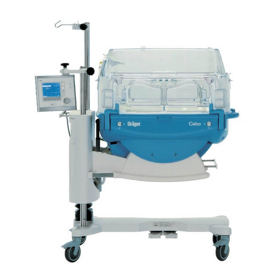
What's what What's what What's what ............8 Front view . -
Page 8: What's What
What's what What's what Front view Canopy (2M 51 108) Access ports Front flap Handle for transport Housing Drawer (2M 50 565) Pedals for height adjustment Height adjustable pillar /Housing support Connection for water heater (LuerLock) 10 X-ray drawer/removable bed 11 Display 12 Control unit 13 Pillar element... -
Page 9: Top View, Bed
What's what Top view, bed Spirit level Hot air duct Connections on the back of the Control Unit Nurse call MEDIBUS* Service RSB (Remote Service Box) optional equipment feature... -
Page 10: Operating Concept
Operating concept Operating concept Control unit Hard Keys 13 14 3 4 5 these permanently defined keys enable the user to select ® various functions of Caleo Scales Bed tilt Menu selection/configuration Menu Changeover key: air/skin temperature control Trend display Skin... -
Page 11: Screen
Operating concept Rotary knob A single rotary knob is used to select and set parameters. Turn knob = select Press knob = confirm Screen By default, the measured values are displayed as numeric values (standard screen). – Set values and actual measured values for air temperature/skin temperature –... -
Page 13: Preparation
Preparation Preparation Preparation ............14 Before using for the first time . -
Page 14: Preparation
Caleo Any equipment mounted on accessories on the handle side must not move with the main unit during height ® adjustment of Caleo (page 121). Screw on pole 38 mm/600 (2M 50 691) or alternatively pole 38 mm/310 (2M 50 688) or alternatively pole 25 mm/600 (2M 50 689). - Page 15 Preparation Mounting accessories Mounting the control unit on the handle side Only technically qualified personnel may move the control unit from the wall side to handle side or vice versa. Fit the basic pole (2M 50 680), see page 16. Screw in the extension pole 38/600 (2M 50 691) or pole 38/310 (2M 50 688).
- Page 16 Preparation Mounting accessories Compact rail (2M 85 337) for pole, 38 mm Max. load 5 kg. This rail must only be mounted by qualified technical staff. For holding accessories, e.g. – monitor Adjust the height of the compact rail to the required height of the mounted accessory.
- Page 17 Preparation Mounting accessories Tray 3020 (M 24 678) Maximum load must not exceed 2 kg! Hang the tray from the standard rail on the wall or handle side and secure in position. Pole extensions The following poles can be fixed to the base pole as extensions: –...
-
Page 18: Front Flap
Preparation Mounting accessories Monitor shelf (2M 50 085) The monitor tray can be mounted on the wall side and/or the handle side. Maximum load must not exceed 20 kg! Shelf for monitor and ventilation equipment. This monitor shelf must only be mounted by qualified technical staff! To fix the monitor shelf: —... -
Page 19: Drawer (2M 50 565)
Fix the O monitor to the handle rail, with the holder. ® Place the sensor capsule in Caleo Route the sensor cable through one of the flexible tubing ports. Where applicable, push the sensor plug into the socket of the O monitor (e.g. -
Page 20: Doors, Ports And Bed
Preparation Doors, ports and bed Doors, ports and bed Access ports To open the access port: Press down the knurled area of the locking bolt. The access port opens. To close the access port: Press the access port until the locking bolt engages. Front flap To open the front flap: Turn the two knobs inwards to the vertical position. - Page 21 Preparation Doors, ports and bed Side flap The side flap is opened and closed in the same way as the front flap (see page 20). Double wall The double wall (2M 51 150) can only be fastened to the canopy (2M 51 108). Fitting the double wall Pull the plunger up as far as it will go.
- Page 22 Grip the double wall with both hands and lift it off. Storing the double wall Fix the hanger (2M 51 152) to the compact rail of the Caleo. Hook the double wall by its plunger to the hanger. Note the set height of the Caleo. Make sure that if the Caleo is lowered the double wall does not touch the floor.
- Page 23 Preparation Doors, ports and bed To remove the canopy: Grasp the handles on the sides of the canopy with both hands. Lift the canopy horizontally off the pillar elements. To replace the canopy: Replace the canopy horizontally, so that the guide pins fit into the holes in the pillar element.
- Page 24 Route the cables or hoses through the flexible grommets and sleeves. ® To route ventilation hoses and cables through the Caleo use the ventilation hose holder (page 18). Hose fixing devices The hose fixing devices (2M 51 140) can only be attached to hose modules with pins (2M 51 139).
- Page 25 Preparation Doors, ports and bed Drainage module The drainage module (2M 51 142) can only be mounted onto the pillar elements (2M 51 154 and 2M 51 156). The drainage module facilitates the installation of hoses for patient drainage. Open the side flap. Positioning the hoses in the drainage module.
- Page 26 Trolley (base frame) with variable height adjustment To use the height adjustment facility: ® Switch on Caleo (see page 43). ® Press the left pedal – Caleo is lowered. ® Press the right pedal – Caleo is raised. Adjust to a comfortable working height.
- Page 27 Press button = the bed will be lowered on the control unit side. The spirit levels show whether the bed is horizontal. ® Spirit levels for the horizontal position of Caleo in the transverse axis. ® Spirit level for the horizontal position of Caleo in the longitudinal axis.
- Page 28 Connect the LuerLock connection to the water connection pipe. Open the clamp on the connection tube. ® Switch on the humidification module on Caleo and set the humidity value (page 58). Water bag: Only use authentic OEM sealed bags filled with sterilised water (Aqua dest.).
- Page 29 The central hospital alarm system may only be connected to the nurse call if Caleo is connected to the mains power supply via a mains power cable or if it has been earthed via the earth connection on the back of the device.
- Page 30 A fault in any of the components in the link between nurse call and central hospital alarm system (e.g. in the electronics for nurse call in Caleo, in the Caleo, power supply or in the alarm generator of the central hospital alarm system, etc.) may result in failure of the nurse call.
-
Page 31: Checking Readiness For Operation
Connect to the mains supply. Check the nurse call system prior to each use. Trigger an appropriate alarm, e.g. switch Caleo to skin temperature mode and remove the skin temperature sensors. If the nurse call system does not sound an alarm, call DrägerService. - Page 32 Checking readiness for operation Before each use Before using the unit, make sure that the following tests have been performed Disinfect hands before each test! Check that the access ports are securely closed Open the access port = press down the knurled area of the locking bolt.
- Page 33 Checking readiness for operation Before each use Check that the double wall is firmly seated Check that the double wall is securely attached to the hood by attempting to lift it off with light force. If the double wall is not securely attached to the hood or the double wall or parts of the locking mechanism are damaged: Do not use the double wall.
- Page 34 Checking readiness for operation Before each use Grasp the handles on the sides of the canopy with both hands. Lift the canopy horizontally off the pillar elements. If the canopy holders are damaged: Call DrägerService. Check that the trough is secure Remove the canopy.
- Page 35 Checking readiness for operation Before each use Activate the self-test, check audible warning tone Switch on the unit = press the on/off switch until it clicks into position. During the self-test, the functions of the machine are checked. The audible signal, alarm beep sequence, screen displays and LEDs must be checked by the user.
- Page 36 Before each use Check the bed tilting mechanism Tilt the bed. ® During the tilting process, the entire housing of the Caleo must move uniformly. If not: Call DrägerService. Do not reach in between the housing and the housing support while the unit is moving! Risk of injury! Return the bed to the horizontal position (see page 27).
- Page 37 Checking readiness for operation Before each use Check the fresh air filter Tilt the unit to remove the fresh air filter more easily (see page 27). Check the expiry date: see the label on the unit. Press down the knurled part of the clip and open the filter flap.
-
Page 39: Operation
® Switching on Caleo ..........43 Using air temperature control . -
Page 40: Operation
When treating larger children, their increased heat production their falling out of the incubator. ® could lead to a rise in the air temperature inside the Caleo – if this is the case remove the double wall. Do not lean or apply weight on the bed when it has been pulled out. - Page 41 The accessory equipment must not collide with the unit ® when adjusting the tilt angle and height of Caleo The accessory equipment on the handle side must not Front flaps move with the main unit during height adjustment of When closing the front flaps, make sure that the patient is not ®...
- Page 42 Otherwise an electrical hazard could be possible. – using O head boxes and delivering pressurised gases, Caleo does not monitor the power supply to external devices. – wear on the bearings of the fan motor, – placing objects on the canopy.
-
Page 43: Switching On Caleo
Operation ® Switching on Caleo ® Switching on Caleo Connect the unit to the mains. Switch on the unit = press the on/off switch until it clicks into place. Position the control unit so that the screen is clearly visible from the working area. -
Page 44: Using Air Temperature Control
The baby’s core temperature must be measured regularly with an independent thermometer! Do not leave the canopy open for any length of time, ® otherwise the air temperature in the Caleo will drop. Adjusting the set value for air temperature Standard set value range... - Page 45 Operation Using air temperature control When using the extended set value range, the the baby's core temperature must be continuously monitored. If the specified set value exceeds the standard set value range – The following message is displayed at the top of the screen »confirm extended range with rotary knob«.
- Page 46 1.5 C or 2.5 C, see page 47, or other alarms are active. ® Reducing the air temperature in Caleo The cooling rate depends on the incubator design and can be increased by: – removing the double wall –...
-
Page 47: Alarms
The measured value flashes, Red bar LED flashes. The alarm tone can be muted for 5 minutes. ® Caleo heats up if necessary to attain the desired interior air temperature setting. The measured value continues to flash, Red bar LED continues to flash. -
Page 48: Using Skin Temperature Control
Use only Dräger sensors or sensors authorised by ® Dräger for the Caleo Disposable sensors must not be cleaned for re-use. If used more than once, the necessary measurement precision cannot be guaranteed. - Page 49 Operation Using skin temperature control Regularly check that the skin temperature sensor is correctly attached to the patient’s skin. If the skin temperature sensor has fallen off, it will measure the air temperature, resulting in possible overheating of the patient (although the air tempera- ture would not rise above 39 Do not use the skin temperature sensor (yellow) or peripheral temperature sensor (white) to measure the rectal temperature.
-
Page 50: Changing Over Between Air/Skin Temperature Control
Do not use skin temperature control mode on twins, ® because Caleo only controls the temperature for one baby. Danger of hypothermia or overheating! Change temperature control mode = press button. - Page 51 The display returns to the standard screen. The previous set value is retained. ® – Wait for 7 seconds: Caleo emits 4 short beeps to prompt the user to press the rotary knob. The display returns immediately to the standard screen. The previous set value...
-
Page 52: Using Skin Temperature Control
The baby’s core temperature must be measured regularly with an independent thermometer! Do not leave the canopy open for any length of time, ® because the air temperature in Caleo will drop! Adjusting the set value Standard set value range... - Page 53 The display returns to the standard screen. The previous set value is retained. ® – Wait for 7 seconds: Caleo emits 4 short beeps to prompt the user to press the rotary knob. The display returns immediately to the standard screen. The previous set value is retained.
- Page 54 The screen returns to standard display mode. The previous set value is retained. ® – Wait for 7 seconds: Caleo emits 4 short beeps to prompt the user to press the rotary knob. The display returns immediately to the standard screen. The previous set value is retained.
-
Page 55: Alarms
Red bar LED flashes. Then: Immediately plug in the sensor ® As long as 3 dashes appear on screen, Caleo does not heat. Danger of hypothermia for the patient! The numerical values in this description are examples. See "Setting alarms" on page 83. - Page 56 Red bar LED flashes. Then: Change the skin temperature sensor. ® As long as 3 dashes appear on screen, Caleo does not heat. Danger of hypothermia for the patient! The alarm tone can be muted for 5 minutes: Suppress intermittent alarm tone = press button Press the rotary knob.
-
Page 57: Using Humidity Control
Operation Using humidity control Using humidity control Connect the humidifier system (see "Using humidifier systems" on page 28). Set humidity control = press button. – The actual value and current setpoint of the humidity control are displayed as bar graphs and numerical values. Soft key assignments: = Do not activate new settings. -
Page 58: Setting Auto Humidity
Decrease set value = turn rotary knob counter-clockwise. Confirm set value = press rotary knob. The maximum attainable humidity level depends on the air temperature and ambient humidity. At high air temperatures or low ambient humidity, the attainable ® humidity level in Caleo is reduced. - Page 59 Operation Using humidity control – The actual value and the current set value of the humidity control are displayed as bar graphs and numerical values. – The display returns to the standard screen. The measured values and set values are displayed.
-
Page 60: Alarms
Operation Using humidity control Alarms In the event of water shortage – The following warning message appears on the screen »Water empty, please refill«, – The alarm tone sequence (3 beeps) is sounded, – The central alarm indicator lights up The measured value flashes, Yellow bar LED flashes. -
Page 61: Using O 2 Control
Operation Using O2 control Using O control Note the physiological risks from O The air in the incubator should only be enriched with O when prescribed by a doctor. Oxygen is classed as a drug. enrichment must be controlled on the basis of measured O saturation in the patient’s blood (SaO Otherwise, there is a danger of hyperoxemia (possibility... -
Page 62: Adjusting The Set Value
Operation Using O2 control Adjusting the set value Standard set value range 21 Vol.% to 40 Vol.% Extended set value range 40.1 Vol.% to 75 Vol.% Default setting 21 % Increase set value = turn rotary knob clockwise. Decrease set value = turn rotary knob counter-clockwise. Confirm set value = press rotary knob. - Page 63 Operation Using O2 control Please bear in mind the risks associated with high O concentrations (see page 40)! If the set value exceeds the standard set value range – The following message is displayed at the top of the screen: »confirm extended range with rotary knob«.
-
Page 64: Alarms
Operation Using O2 control Alarms Alarm limits can be changed in the configuration (see page 84). Example: if the deviation between the set and measured O concentration exceeds ±5 % – The screen displays the warning message »Oxygen deviation above 5 %«, –... -
Page 65: Using The Day/ Night Setting
Operation Using "Day and Night" Using "Day and Night" With Day and Night, the screen can be displayed at four different brightness levels. After restarting the device, e.g. after a power failure, the screen is displayed in the last selected mode. On starting up the device, the screen is displayed with maximum brightness. -
Page 66: Selecting Menus
Ensure that all hoses and cables are routed correctly and safely without obstruction! In Kangaroo mode the incubator is operated in air temperature control mode. ® If Caleo was previously operated in air temperature mode, the set value for air will be activated in Kangaroo mode. ® If Caleo was previously operated in skin temperature mode, the last air temperature value will be loaded as set value. - Page 67 Operation Selecting menus Activating Kangaroo mode Display the main menu = press »menu« button. Select "Kangaroo mode" from the menu. Select item = turn the rotary knob. Confirm and activate item = press the rotary knob. – The screen displays the following advisory message: »To leave the current mode please confirm the new Kangaroo Mode with rotary knob«.
-
Page 68: Alarms
Operation Selecting menus Alarms Alarm limits can be changed in the configuration (page 83). If the skin temperature of the yellow skin temperature sensor (skin 1) falls below the alarm limit set in the configuration: – The screen displays the warning message »Skin 1 temperature below 36.0 C«... - Page 69 To maintain Kangaroo mode = press » « key. ® – Wait for 7 seconds: Caleo emits 4 short beeps to prompt the user to press the rotary knob. The display returns immediately to the standard screen. The previous set value is retained.
-
Page 70: Trend Display
Operation Selecting menus Trend display The trend screen is used for the graphical and numerical display of the measurement parameters. The data window always shows the last data in the selected time interval. In addition, the current measured values and set values are numerically displayed. - Page 71 Operation Selecting menus Select the desired trend display from the displayed list. Defaults: – Air temperature trend – Zoom factor 3 hours Select trend = turn the rotary knob. Activate trend = press the rotary knob. Back to menu = press » «...
- Page 72 Operation Selecting menus Display the zoom menu = press the »zoom« button. Select the desired zoom from the menu. Select zoom = turn the rotary knob. Activate zoom = press the rotary knob. Back to menu = press » « button (soft key). Return to trend selection = press the »trend«...
-
Page 73: Trend Analysis
Operation Selecting menus Trend analysis Trend analysis is used for the graphical and numerical display of measurement parameters and their associated set values. The data window can be selected at will to any period over the last 7 days. Trend analysis can therefore be used to evaluate thermo- monitoring data. - Page 74 Operation Selecting menus – The trend graph for the selected measured value is displayed on the screen. Default values: Trend 1 Skin temperature Trend 2 Air temperature Zoom 3 hours The selected value is displayed as a trend graph. In this graph, the trend curve of the measured value is overlaid on the corresponding set value curve.
-
Page 75: Trend Selection
Operation Selecting menus Trend selection A trend graph can be selected with the soft keys. Soft Key assignments: = Cancel. New settings will not be activated. trend 1 = Select trend 1. trend 2 = Select trend 2. zoom = Select time interval. Select trend 1: Display the trend 1 menu = press soft key. - Page 76 Operation Selecting menus The newly selected trend 2 is displayed on the screen under- neath trend 1. In addition, a second data window containing the relevant parameters is opened next to trend 2. The time cursor and time range (zoom) are the same for both trend displays. The »disable«...
-
Page 77: Cleaning Mode
Operation Selecting menus Cleaning mode ® – Cleaning mode is only available if Caleo is equipped with humidity control. – Cleaning mode can only be used if there is not a patient in ® the Caleo – Only use cleaning mode with an ambient humidity of >10 % relative humidity. - Page 78 Start Cleaning Mode = press both soft keys simultaneously. The water heater is boiled dry. The heater is then cooled. Risk of burns on contact with the heater! ® Do not disassemble Caleo during cleaning mode.
- Page 79 Selecting menus – The screen indicates when cleaning mode is complete. Confirm end of cleaning mode = press rotary knob. ® Caleo performs a restart. After ending cleaning mode: ® – Disinfect and clean Caleo (see "Disinfecting/Cleaning/ Sterilising" on page 94).
-
Page 80: Configuration
Operation Configuration Configuration In configuration mode, you can set – Language, date and time – System parameters and – Alarm parameters you can obtain information on – sensors – the software version. Activating configuration mode Activate configuration mode = hold down the »menu« button for 4 seconds. -
Page 81: Language/Date/Time
Operation Configuration Language/date/time Select language/date/time = Turn and press the rotary knob. – The language selection box is highlighted by a bright border. Select language = turn the rotary knob. Confirm language = press the rotary knob. – The selected language is displayed on the screen. Follow the same procedure to set the date format, date and time. -
Page 82: Setting System Parameters
It is only possible to set the altitude above sea level if ® automatic O control is integrated in Caleo If the local altitude is entered incorrectly, the measurement accuracy of the O sensors will be reduced (e.g. 1.5 % additional error for 1000 m difference in altitude). -
Page 83: Setting Alarms
Operation Configuration Setting alarms Select alarms = turn and push the rotary knob. – The menu that is then displayed allows the user to select Kangaroo mode, the initial volume of the audible alarms and the alarm limits for temperature control and O control. - Page 84 Operation Configuration Initial volume (sound intensity) of the alarms: Adjustment range: 1 to 8 Default: – The initial sound intensity is highlighted by a light background. Set an initial sound intensity = turn rotary knob. Confirm initial sound intensity = press rotary knob. The screen returns to the alarm settings menu (page 83).
-
Page 85: O 2 Sensor Information
Operation Configuration sensor information The screen displays the following information for the sensors used: – Date of manufacture – Date of last calibration – Date of next calibration. Viewing software information – The software version and the number of operating hours are displayed on the screen. -
Page 86: Lock Key Pad Functions
Operation Lock key pad functions Lock key pad functions To lock further on-screen setting = press button. The LED on the button lights up. – After 4 seconds, all screen functions are locked, except for: Lock key pad function Alarm suppression Rotary knob Bed tilt. -
Page 87: Weighing Scale
It is suggested that weighing should only be conducted when the trolley castors on Caleo are locked. This helps to cushion vibrations and increases the accuracy of weight measurements. - Page 88 Before the weighing process, make sure that both knobs are set to the scales position ® During the weighing process, Caleo must not be exposed to any vibrations. During the weighing process, no objects may be placed on the bed surface.
- Page 89 Operation Weighing scale During weighing, the user is guided through the sequence of operating steps by the following prompts. Lift the baby off the bed. The device waits until the scales have stabilised and are at rest for 3 seconds. –...
-
Page 90: Weighing Without Tare
Preparing for weighing ® Set Caleo to the horizontal position. Check with the aid of the built-in water levels – see page 27. Set both knobs to the horizontal position see page 24. -
Page 91: Ending Operation
The screen displays the last weight as advisory text for the next 10 minutes. Ending operation Before turning off Caleo, acknowledge all active alarms with high risk potential. Otherwise the nurse call system will continue to indicate the active alarm after the device has been switched off. -
Page 93: Care
Care Care Disinfecting/Cleaning/Sterilising ........94 Stripping down . -
Page 94: Disinfecting/Cleaning/Sterilising
Disinfecting/Cleaning/Sterilising Disinfecting/Cleaning/Sterilising Risk of burns on contact with the heater When the incubator is closed, the heater is still hot enough to cause serious burns for a long time after switching off (still approx. 70 C after 1 hour). Clean and disinfect the incubator thoroughly: –... - Page 95 ABS (acrylonitrile/ butadiene/ styrene) Intermediate Styrene-butadiene thermo foam element injection molded material ABS (acrylonitrile/ butadiene/ styrene) X-ray drawer Polystyrene thermo foam injection molded material Housing Polystyrene thermo foam injection molded material ™ ® SoftBed Caleo Polyurethane/ polyester...
-
Page 96: Stripping Down
Disinfecting/Cleaning/Sterilising Stripping down Stripping down Check the fresh air filter Tilt the unit to remove the fresh air filter more easily (see page 27). Check the expiry date: see the label on the unit. Press down the knurled part of the clip and open the filter flap. - Page 97 Disinfecting/Cleaning/Sterilising Stripping down Removing the water supply Close the clamp on the connection tube. Remove and dispose of the water bag and connection tube Remove the water container from the holder. Detach the connection tube from the water container and water connection pipe.
- Page 98 Disinfecting/Cleaning/Sterilising Stripping down ® Place Caleo horizontal (see page 27). Switch on cleaning mode (see page 77). After cleaning mode* has completed or if humidity control is not provided: Switch off the incubator and disconnect from mains. Remove any auxiliary equipment installed (for care instructions see the specific Instructions for Use of the equipment concerned).
- Page 99 Disinfecting/Cleaning/Sterilising Stripping down Tip the bore sleeve to the side and remove it. Tip the centering lugs to the side and remove them. Remove visible soiling with a disposable cloth. Wipe-disinfect the double wall surfaces. After allowing the disinfectant time to take effect (see manufacturer's specifications), wipe the surface with a clean damp disposable cloth and then rub dry.
- Page 100 Disinfecting/Cleaning/Sterilising Stripping down Open the front flap Turn the two locking knobs inwards as far as they will go and fold down the front flap. Fold out the adjustable double walls to clean them. Open the side flaps in the same way. Remove visible soiling with a disposable cloth and detergent.
- Page 101 Disinfecting/Cleaning/Sterilising Stripping down Remove the X-ray drawer Using the recessed handle, pull out the X-ray drawer as far as it will go. Tilt the drawer upwards and pull it out of the unit. Remove visible soiling with a disposable cloth and detergent.
- Page 102 Disinfecting/Cleaning/Sterilising Stripping down Base frame/body Remove visible soiling with a disposable cloth and detergent. Wipe-disinfect the surfaces. After allowing the disinfectant time to take effect (see manufacturer's specifications), wipe the surface with a clean damp cloth and then rub dry. Remove any impurities near the slits of the sensor unit.
-
Page 103: Before Reusing For A Patient
Disinfecting/Cleaning/Sterilising Before reusing for a patient Before reusing for a patient Check that the system has been cleaned and disinfected in conformity with the regulations of the hospital. Reassemble the equipment with disinfected hands. Refit all equipment – see "Stripping down", page 96. When inserting the trough, make sure that both holders click into place. - Page 104 Check that the incubator is ready for operation – see "Before each use" on page 31. To remove possible disinfectant residue, it is recommend running the incubator in standby mode. ® Switch on Caleo (see page 43). Activate air temperature control (see page 44). ® Run Caleo at 37 C with opened flaps.
-
Page 105: Care List
Disinfecting/Cleaning/Sterilising Care list Care list What How often Disinfect and clean Sterilise Reusable components Care intervals Wipe Cleaning and Steam disinfecting machine Connection tube Replace weekly and with each change of patient Water container Change of patient/weekly Water connection pipe Change of patient/weekly Double wall Change of patient/ weekly... -
Page 106: Maintenance Intervals
Maintenance intervals Maintenance intervals Disinfect and clean the incubator or the relevant parts before each maintenance operation, even when returning the equipment for repair purposes! Disconnect from the mains before each maintenance operation. Risk of electric shock. Intervals Who? when weekly every every... -
Page 107: Disposal
Disposal Disposal Disposal of the connection tube and fresh air filter – with household waste. Disposal of O sensors and battery – Do not throw into the fire. Risk of explosion. – Do not force open: risk of chemical burns. –... - Page 108 Disposal Care list...
-
Page 109: Troubleshooting - Error Messages
Troubleshooting – Error Messages Troubleshooting – Error Messages Troubleshooting – Error Messages ....... . . 110 Troubleshooting –... - Page 110 Troubleshooting – Error Messages Troubleshooting – Error Messages All error messages are displayed on the screen. They are listed in the table below in alphabetical order. See also "Alarm description" on page 136. Message Cause Remedy Duration audible alarm muted Adjust.
- Page 111 Troubleshooting – Error Messages Message Cause Remedy Duration audible alarm muted Device Error Device fault. Switch off device and then switch on again. with number display. Call DrägerService. Continuous alarm tone, Red bar LED lights up. Fan inoperable Fan defective. Check fan impeller.
- Page 112 Troubleshooting – Error Messages Message Cause Remedy Duration audible alarm muted Oxygen deviation above 5 % Difference in measured O Fully close the hood, front flap, 2 min concentration is greater than 3 removable bed, X-ray drawer, (can be set on 3 or 5 % – or 5 %.
- Page 113 Troubleshooting – Error Messages Message Cause Remedy Duration audible alarm muted Skin 1 more than 4.0 C above skin 2 Kangaroo mode alarm: Check patient's heat exchange. 15 min temperature difference (see "Configuration" on page 83) Check configuration (page 80). between the skin temperature The measured values for skin tempera- (yellow) and peripheral...
- Page 114 Troubleshooting – Error Messages Message Cause Remedy Duration audible alarm muted Skin 2 temperature below 34.0 Kangaroo mode alarm: Increase heat supply to the 15 min patient. (see "Configuration" on page 83) Peripheral temperature is falling below the alarm limit. Check configuration.
-
Page 115: Troubleshooting - Faults
Troubleshooting – Faults Troubleshooting – Faults All faults are listed in the table below in alphabetical order. See also "Alarm description" on page 136. Fault Cause Remedy Base frame cannot be set to the Motor overheating. Wait for at least 2 minutes. After this tilted position. -
Page 117: Technical Data
Technical Data Technical Data Technical Data ..........118 Environmental conditions . -
Page 118: Technical Data
Technical Data Technical Data Environmental conditions In normal operation Temperature C to 35 Atmospheric pressure 600 hPa to 1060 hPa Relative humidity 10 to 95 %, no dew formation During storage/transport Temperature –20 C to 60 Atmospheric pressure 210 hPa to 1060 hPa Relative humidity 10 to 95 %, no dew formation Operating data... -
Page 119: Performance Characteristics
C) being fully attained. Use the double wall. The maximum achievable humidity depends on the air temperature and the ambient humidity. ® The humidity which can be achieved in the Caleo reduces in the event of higher air temperature and lower ambient humidity. - Page 120 For a detailed description of the interface protocol please see the manual "Dräger RS 232 MEDIBUS Protocol Definition" 90 28 320 (German), 90 28 258 (English) and "MEDIBUS for Dräger Paediatric Devices" 90 29 204 (German), 90 29 205 (English) Caleo Monitor 9-pin sub-D 9-pin sub-D...
-
Page 121: Dimensions
Technical Data Central alarm (optional) Outlet for the connection to in-house call systems (nurse call) Operating voltage Max. 24 V Current Max. 250 mA Power Max. 3 W Dimensions Unit (Width x Depth) 1167 mm x 687 mm Height of overall unit with variable pillar 1220 mm to 1520 mm Height of overall unit with fixed pillar 1270 mm/1370 mm/1470 mm... -
Page 122: Classification
Technical Data or alternatively with installed monitor support tray (2M 50 085) max. 20 kg max. 20 kg max. 5 kg max. 5 kg Wall side Handle max. side 5 kg max. 7 kg max. 2 kg (on both sides) Classification according to EC Directive 93/42/EEC Appendix IX Class IIb... -
Page 123: Description
Bed and mattress ..........125 ® ® ™ Twins in the Caleo (Caleo Twincubator ) ......125 X-rays . -
Page 124: Description
5 kg and a body length ® of 55 cm. Inside the Caleo patient "capsule", the patients are supplied with a controlled amount of heat and, if necessary,... -
Page 125: Bed And Mattress
® 5 kg. When treating twins in an incubator, Caleo must be operated in air control mode. The treatment of twins together in a single incubator can help to prevent post-natal separation trauma. -
Page 126: X-Rays
® The weighing scale in the Caleo comprises four weighing elements located underneath the bed, an electronic measuring and analysis unit and a special page on the control monitor. -
Page 127: Airflow Routing
The patient lies in a calm zone with low airflow speeds. Heat loss due to flow is kept to a minimum. When opening the ® ™ large flaps or access ports (Caleo JumboPorts ), an efficient hot air curtain remains to prevent cooling in the patient compartment. -
Page 128: Skin Temperature Measurement
A temperature reduction takes longer, due to the good thermal insulation of the incubator. ® Note on setting the air temperature set value in the Caleo The patient has limited – heat loss due to airflow, because the airflow rate above the mattress is low. -
Page 129: Skin Temperature Control
(skin 1) and compared with the set value. The difference between the set value and the measured actual ® value is used to control the air temperature in Caleo between a minimum of 20 C and a maximum of 39... -
Page 130: Kangaroo Mode
Switchover to "Standby" mode ® Since the baby is no longer inside Caleo during "Kanga- rooing", the baby's skin temperature should no longer be used as a measure for controlling the air temperature inside the incubator. - Page 131 In order to perform this monitoring with as little nuisance as possible to mother/father ® and baby, Caleo provides the facility for activating special Kangaroo mode alarms during operation in Kangaroo mode. These alarms are set in the configuration. The following alarm limits are set: –...
-
Page 132: O 2 Enrichment
Description ∆T max. alarm This alarm is triggered if the difference between Skin T1 and Skin T2 is above the set value (risk of hypothermia). Alarm deactivated ˚C Skin T 1 ∆T >4 ˚C Skin T 2 t (min) Alarm activated Each of these alarms can either be set or switched in advance to "OFF". -
Page 133: Closed-Loop Humidity Control
(air too humid), the humidifier receives a signal to allow less water vapour into the patient capsule. ® The relative humidity inside Caleo therefore falls. AUTO humidity When AUTO mode is set, the set value for the relative humidity... -
Page 134: Cleaning Mode
(see page 97). ® Cleaning mode may only be used if Caleo is empty. Cleaning mode is activated on the control panel after pressing the "Menu" button and selecting the "Cleaning Mode" option. -
Page 135: Safety Systems
Any error message will be displayed even when the defective module is switched off. ® Any unauthorised operating state will cause Caleo to switch off the heater or water heater as a safety precaution. -
Page 136: Alarm Description
Visual signals on the control panel Red bar LED Yellow bar LED Red LED next to the symbol ® Caleo distinguishes between 5 different alarm priorities: Serious device faults Device fault: Continuous tone that cannot be muted, and Red bar LED lights up. -
Page 137: Key To The Symbols Used
Description Information No bar LED lights up, no acoustic alarm signal For example: – Humidity deviation above 10 %. Information messages on the active alarm are displayed on screen. If another alarm occurs while the alarm tone is muted, the alarm tone will be reactivated. See "Alarm suppression"... -
Page 138: Labelling
Description Labelling Connections for skin temperature sensors, page 48 Auxiliary power sockets, page 29, Technical Data, 2 A max. Σ page 118 Type designation for T 2 H 250V IEC127-2/V fuses for auxiliary power sockets Type designation F 10A UL 248-14 for system fuses Equipotential bonding On/off switch,... - Page 139 Description page 31 Never leave baby unattended when doors are open ! Do not tilt canopy forwards, page 33 page 9 and WARNING! page 127 Never block or obstruct air vents! Risk of burning! page 24 Always close X-ray tray tightly ! page 121 max 5 kg, 11lbs page 121...
- Page 140 Description Castor without brake function, page 26 Stop...
-
Page 141: Order List
Order list Order list Designation and description Part No. ® Caleo 2M 50 555 / Caleo incubator with air and skin servo 2M 50 000 ™ modes, ThermoMonitoring (temperature probes optional) With large front and rear access panels, ™ 6 extra large access ports (Jumbo Ports detachable hood which opens to either side, electronic bed inclination (±13... - Page 142 2M 22 090 Stand for phototherapy unit 4000 2M 21 190 Accessories for care Cally 2M 30 462 DC starter pack Caleo 2M 30 478 "Hug it" storage aid 2M 30 468 "Caleo" incubator hood 2M 30 467 Cot bumper storage aid...
- Page 143 Order list Designation and description Part No. Spare parts and wearing parts Caleo canopy 2M 51 108 "Feeding grommet" plug 2M 51 109 Double wall, complete 2M 51 150 Water container set, complete 2M 50 040 Cap for the water container...
-
Page 144: Parts List
Parts List Parts List As an alternative to the part numbers listed in the Order List, the following parts and devices, which are no longer supplied by Dräger, may be used. Designation and description Part No. Babyguard 57 70 025 PT 8000 2M 20 520 PT 800... -
Page 145: Index
......... . 94 ® Twins in the Caleo ......125 Care intervals . - Page 146 Index Fire hazard from supply of O ..... . . 40 Operating data ....... . . 118 Fitting accessories .
- Page 147 Trough ......... 34 ® Twins in the Caleo , Description .
- Page 148 These Instructions for Use apply only to ® Caleo with Serial No.: If no Serial No. has been filled in by Dräger these Instructions for Use are provided for general information only and are not intended for use with any specific machine or device ç...
Need help?
Do you have a question about the caleo and is the answer not in the manual?
Questions and answers