Dräger Caleo Instructions For Use Manual
Neonatal incubator
Hide thumbs
Also See for Caleo:
- Instructions for use manual (148 pages) ,
- Instructions for use manual (178 pages) ,
- Cleaning (7 pages)

Related Manuals for Dräger Caleo


Summary of Contents for Dräger Caleo
- Page 1 Caleo ® Neonatal incubator WARNING To properly use this medical device, read and comply Software 2.n with these Instructions for Use. Instructions for Use...
- Page 2 Accessories mounted on the handle side do not move ® with the main unit during the height adjustment of Caleo The text provides explanations and instructs the user step-by- (see page 123). Hoses or cables can be stretched during the height adjustment of Caleo.
-
Page 3: Table Of Contents
Table of contents Table of contents Intended Use What's what Operating concept Preparation Check readiness for operation Operation Preparation Maintenance intervals Disposal Messages – Cause – Remedy Error – Cause - Remedy Technical Data Description Order List Parts List Index... - Page 4 For Your Safety and that of Your Patients Definition of target groups Definition of target groups Maintenance WARNING Users, maintenance personnel and professionals are defined as the target groups for this medicine device. The medical device must be inspected and serviced reg- These target groups were trained to handle the medical device ularly by professionals who possess the required quali- and have the necessary specialized knowledge and training,...
- Page 5 For Your Safety and that of Your Patients Definition of target groups Connection to other devices Patient safety may be achieved by a wide variety of means ranging from electronic surveillance of medical device perfor- Device combinations approved by Dräger (see Instructions for mance and patient condition to simple, direct observation of Use of the individual devices) meet the requirements of the clinical signs.
-
Page 6: Intended Use
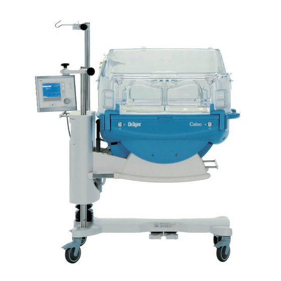
Intended Use Intended Use Therapy system for premature babies and sick neonates up to a body weight of 5 kg or a body length of 55 cm, for the controlled supply of warmth, humidity and O enrichment* in the patient capsule. For the therapy of twins, the total body weight is limited to 5 kg. -
Page 7: What's What
What's what What's what What's what ............8 Front view . -
Page 8: What's What
What's what What's what Front view Canopy (2M 51 108) Access ports Front flap Handle for transport Housing Drawer (2M 50 565) Pedals for height adjustment* Height adjustable pillar*/Housing support Connection for water heater (LuerLock) 10 X-ray drawer/removable bed 11 Screen 12 Control panel 13 Pillar element 14 Double wall* (2M 51 150) -
Page 9: Top View, Bed
What's what Top view, bed Spirit levels Hot air duct Connections on the back of the Control Unit Nurse call MEDIBUS* Service RSB (Remote Service Box) optional equipment feature... -
Page 10: Operating Concept
Operating concept Operating concept Control panel Hard Keys 13 14 3 4 5 these permanently defined keys enable the user to select ® various functions of Caleo Scale Bed tilt Menu selection/configuration Menu Changeover key: air/skin temperature control Trend display Skin... -
Page 11: Screen
Operating concept Rotary knob A single rotary knob is used to select and set parameters. Turn knob = select Press knob = confirm Screen By default, the measured values are displayed as numeric values (standard screen). – Set values and actual measured values for air temperature/skin temperature –... -
Page 13: Preparation
Preparation Preparation Preparation ............14 Before using for the first time . -
Page 14: Preparation
Accessories mounted on the handle side do not move ® with the main unit during the height adjustment of Caleo (see page 123). Hoses or cables can be stretched during the height adjustment of Caleo. Lay hoses or cables such that they are sufficiently long during the height adjustment. - Page 15 Preparation Mounting accessories NOTE Contol unit without space for free swivel movement. Risk of damage to control unit. Make sure there is sufficient space to swivel the unit. WARNING Mounting the control unit on the handle side. Only specialized technical personnel may move the control unit from the wall side to the handle side or vice versa.
- Page 16 Preparation Mounting accessories Compact rail (2M 85 337) for pole, 38 mm Max. load 5 kg. WARNING Only specialized technical personnel should perform the installation, else there is risk of incorrect installation and therefore, risk of injury to the user. For fixing accessories, e.g.
- Page 17 Preparation Mounting accessories Shelf 3020 (M 24 678) Maximum load must not exceed 2 kg! Hang the shelf from the standard rail on the wall or handle side and secure in position. Pole extensions The following poles can be fixed to the base pole as exten- sions: –...
- Page 18 Preparation Mounting accessories Monitor shelf (2M 50 085) The monitor shelf can be mounted on the wall side and/or the handle side. Maximum load must not exceed 20 kg! Shelf for monitor and ventilation equipment. WARNING Only professionals should perform the installation, else there is risk of incorrect installation and therefore, risk of injury to the user.
- Page 19 Fix the O monitor to the compact rail using the holder. ® Place the sensor capsule in Caleo Route the sensor cable through one of the flexible tubing grommets. Where applicable, push the sensor plug into the socket of the O monitor (e.g.
-
Page 20: Doors, Ports And Bed
Preparation Doors, ports and bed Doors, ports and bed Access ports To open the access port: Press down the knurled area of the locking bolt. The access port opens. To close the access port: Press the access port closed until the locking bolt engages. Front flap To open the front flap: Turn the two knobs inwards to the vertical position. - Page 21 Preparation Doors, ports and bed Side flap The side flap is opened and closed the same way as the front flap (see page 20). Double wall The double wall (2M 51 150) can only be fastened to the canopy (2M 51 108). Fitting the double wall Pull the plunger up as far as it will go.
- Page 22 The red shaft of the plunger will then be visible. Grip the double wall with both hands and lift it off. Storing the double wall Fix the hanger (2M 51 152) to the compact rail of the Caleo. Hook the double wall by its plunger to the hanger. CAUTION If Caleo is lowered too far, the double wall may touch the floor.
- Page 23 Preparation Doors, ports and bed To remove the canopy: Hold the canopy with both hands using the handles on the side. Lift the canopy horizontally off the pillar elements. To replace the canopy: Replace the canopy horizontally, so that the guide pins fit into the holes in the pillar element.
- Page 24 Route the cables or hoses through the flexible tubing grommets The hose holder for vetilation hoses is provided to route venti- ® lation hoses and cables through Caleo (page 18). Hose fixing devices The hose fixing devices (2M 51 140) can only be attached to hose modules with pins (2M 51 139).
- Page 25 Preparation Doors, ports and bed Drainage module The drainage module (2M 51 142) can only be mounted onto the pillar elements (2M 51 154 and 2M 51 156). The drainage module facilitates the installation of hoses for patient drainage. Open the side flap. Positioning the hoses in the drainage module.
- Page 26 ® Press the left pedal – Caleo is lowered. ® Press the right foot pedal – Caleo is raised. Adjust to a comfortable working height. When the height stops changing, the trolley is at its end position. Release the pedal.
- Page 27 Press key = the bed will be raised on the control unit side. Press key = the bed will be lowered on the control unit side. The spirit levels show whether the bed is horizontal. ® Spirit levels for the horizontal alignment of Caleo in the transverse axis. ®...
- Page 28 Bleed the transfer set (let sterilised water drain off). Close the clamp on the transfer set. Open the clamp on the transfer set. ® Switch on the humidification module on Caleo and set the humidity value (page 59). Water tank empty = Water shortage alarm is triggered on ®...
- Page 29 Connections may only be made by specialized technical personnel. Caleo does not monitor the power supply to external devices. WARNING The user or patient can be in danger of a electric shock if the power consumption of accessories or the ground leakage current is too high.
- Page 30 The central hospital alarm system may only be connected to the nurse call if Caleo is connected to the mains power supply via a mains power cable or if it has been grounded via the grounding bolt on the back of the device.
- Page 31 For information on parameters please see Technical Data, page 122. WARNING Do not connect external devices to Caleo if Caleo is not connected to the power supply socket via a power cable or if there is no grounding via the grounding bolt on the back of the unit.
-
Page 32: Check Readiness For Operation
Connect the power plug to the mains supply. Check the nurse call system prior to each use. Trigger an appropriate alarm, e.g. switch Caleo to skin temperature mode and remove the skin temperature sensors. If the nurse call system does not sound an alarm, call DrägerService. - Page 33 Check readiness for operation Before Every Use Disinfect hands before each test! WARNING If the access ports do not open and close correctly, danger to the patient. Check that the access ports are securely closed Open the access port = press down the knurled area of the locking bolt.
- Page 34 Check readiness for operation Before Every Use WARNING If the side flap does not have stable base, danger to the patient. Check that the side flap is securely engaged. Open the side flap and fold it down (see page 21). Fold up the side flap and press it closed.
- Page 35 Check readiness for operation Before Every Use Raise the side prop. Lower the canopy until the prop is secured in the slot of the canopy. Repeat the test on the other side. If the canopy fails to remain open: Call DrägerService. Hold the canopy with both hands using the handles on the side.
- Page 36 Check readiness for operation Before Every Use Removing the bed Open the front flap and fold it down. Turn both knobs to the vertical position marked Grasp the bed by the recessed handle or by the knobs and pull it out towards the front as far as it will go. Push the bed back until it clicks into place, Turn both knobs to the position marked Close the front flap.
- Page 37 Check readiness for operation Before Every Use Check the bed-tilt mechanism Tilt the bed. ® During the tilting process, the entire housing of the Caleo must move uniformly. If not: Call DrägerService. CAUTION Danger of getting crushed between housing and housing support if the position is tilted, danger to the patient.
- Page 38 Check the fresh air filter To simplify the removal of the fresh air filter, tilt the device page 27. Check the expiry date: see the label on the unit. Press down the knurled part of the clip and open the filter flap.
-
Page 39: Operation
® Switching on Caleo ..........44 Using air temperature control . -
Page 40: Operation
Avoid additional heat sources. When treating larger babies, their increased heat production ® could lead to a rise in the air temperature inside the Caleo WARNING Remove the double wall. Risk to patient due to too low or too high core temperature. - Page 41 CAUTION eyes) or hypoxemia (possibility of brain damage). To avoid bacterial contamination when reaching through the access ports into the patient capsule of Caleo, observe suit- WARNING able hygiene measures and, if possible, do not touch the Risk of impairment of device functioning due to the surface of the patient capsule.
- Page 42 Fluid balance can be affected adversely by phototherapy. NOTE The supply of fluid to the patient must be increased, e.g. Risk of damage to Caleo or accessories when adjusting the tilt by parentral infusion, to compensate for the increased angle and height.
- Page 43 (page 135). WARNING Risk of electric shock from external devices connected to the interface if Caleo is not connected to the power supply socket via the power cable or not grounded via the grounding bolt on the back of the unit.
-
Page 44: Switching On Caleo
Operation ® Switching on Caleo Switching on Caleo ® Connect the incubator to the mains power supply. Switch on the unit = press the on/off switch until it clicks into position. Position the control unit so that the screen is clearly visible from the working area. -
Page 45: Using Air Temperature Control
The display returns to the standard screen. The previous set value is retained. ® – Wait for 7 seconds: 4 short beeps are emitted. Caleo reminds the user to press the rotary knob. The display returns to the standard screen. The previous set value is retained. - Page 46 Operation Using air temperature control WARNING Overheating of patient is possible if the extended set value range is used. Monitor the body temperature continuously. If the set value exceeds the standard set value range – The following message appears in the upper section of the screen.
- Page 47 The display returns to the standard screen. The previous set value is retained. ® – Wait for 7 seconds: 4 short beeps are emitted. Caleo reminds the user to press the rotary knob. The display returns to the standard screen. The previous set value is retained.
-
Page 48: Alarms
Measured value flashes, Red bar LED flashes. The alarm tone can be muted for 5 minutes. ® Caleo heats up the patient capsule if necessary to attain the desired air temperature setting. The measured value continues to flash, Red bar LED continues to flash. -
Page 49: Using Skin Temperature Measurement
Operation Using skin temperature measurement Using skin temperature measurement NOTE Directly before using the skin temperature sensors: Insert the yellow skin temperature sensor or white peripheral skin temperature sensor in the yellow or white socket and wait for the measurement signal to appear on screen. WARNING To protect the device againt electrostatic discharging, do not touch the socket... - Page 50 Using skin temperature measurement WARNING Risk to patient from using skin temperature sensors that are not approved by Dräger for Caleo. Overheating or hypothermia of patient is possible due to large measure- ment deviation. Use only Dräger skin temperature sensors or sensors ®...
-
Page 51: Changing Over Between Air/Skin Temperature Control
Do not use skin temperature control on patients who have fever. Use air temperature control, see page 45. WARNING When treating twins in Caleo, the skin temperature control monitors the temperature of one patient only. Danger of hypothermia or overheating. - Page 52 The display returns to the standard screen. The previous set value is retained. ® – Wait for 7 seconds: 4 short beeps are emitted. Caleo reminds the user to press the rotary knob. The display returns to the standard screen. The previous set value is retained.
-
Page 53: Using Skin Temperature Control
Do not use skin temperature control on patients who have fever. Use air temperature control, see page 45. WARNING When treating twins in Caleo, the skin temperature control monitors the temperature of one patient only. Danger of hypothermia or overheating. - Page 54 The display returns to the standard screen. The previous set value is retained. ® – Wait for 7 seconds: 4 short beeps are emitted. Caleo reminds the user to press the rotary knob. The display returns to the standard screen. The previous set value is retained.
- Page 55 The display returns to the standard screen. The previous set value is retained. ® – Wait for 7 seconds: 4 short beeps are emitted. Caleo reminds the user to press the rotary knob. The display returns to the standard screen. The previous set value is retained.
-
Page 56: Alarms
Operation Using skin temperature control Alarms Alarm limits can be changed in the configuration (page 86). If the deviation between the set and measured skin tempera- ture exceeds ±0.5 – The alarm message appears on the screen. »Skin temperature deviation. 1 more than 0.5 C«, –... - Page 57 Using skin temperature control WARNING If the skin temperature sensor is not inserted or if it is defective, Caleo does not warm up as long 3 dashes are displayed on the screen. Danger of hypothermia for the patient. Inserting or replacing the skin temperature sensor.
-
Page 58: Using Humidity Control
Operation Using humidity control Using humidity control Connect the humidifier system (see "Using humidifier systems" on page 28). Set humidity control = press key. – The actual value and the current set value of the humidity control are displayed as bar graphs and numerical values. Soft key assignments: = Do not activate new settings. -
Page 59: Setting Auto Humidity
Reduce set value = turn rotary knob anti-clockwise. Confirm set value = press rotary knob. NOTE At high air temperatures or low ambient humidity, the attain- ® able humidity level in Caleo is reduced. The maximum attainable humidity level depends on the air temperature and ambient humidity. - Page 60 Operation Using humidity control – The actual value and the current set value of the humidity control are displayed as bar graphs and numerical values. – The display returns to the standard screen. The actual measured values and the set values are displayed.
-
Page 61: Alarms
Operation Using humidity control Alarms In the event of water shortage – The alarm message appears on the screen. »Water tank is empty, please refill«, – The alarm tone sequence (3 beeps) is sounded, – The central alarm indicator lights up The measured value flashes, Yellow bar LED flashes. -
Page 62: Using O 2 - Control
Operation Using O2- control Using O control WARNING Risk to patient due to hyperoxemia (possibility of damage to the eyes) or hypoxemia (possibility of brain damage) from O therapy. The air in the incubator should only be enriched with O when prescribed by a doctor. -
Page 63: Adjusting The Set Value
Operation Using O2- control Adjusting the set value Standard set value range 21 Vol.% to 40 Vol.% Extended set value range 40.1 Vol.% to 75 Vol.% Default setting 21 % Increase set value = turn rotary knob clockwise. Decrease set value = turn rotary knob counter-clockwise. Confirm set value = press rotary knob. - Page 64 Operation Using O2- control – The message » >40 %« appears on the screen. – The following message appears in the upper section of the screen. »set value with rotary knob« Confirm the set value = press the rotary knob. –...
-
Page 65: Alarms
Operation Using O2- control Alarms Alarm limits can be changed in the configuration (page 86). If the deviation between the set and measured O concentra- tion is more than ±5 % – The alarm message appears on the screen. deviation more than 5 %«, »O –... -
Page 66: Using "Day And Night
Operation Using "Day and Night" Using "Day and Night" With Day and Night, the screen can be displayed at four different brightness levels. On starting up the device, the screen is displayed with maximum brightness. After restarting the device, e.g. after a power failure, the screen is displayed in the last selected mode. -
Page 67: Selecting Menus
Operation Selecting menus Selecting menus Select menu = press the »menu« key. The required mode can be selected from the menu displayed: Select item = turn the rotary knob. Confirm menu option = press the rotary knob. Kangaroo mode See page 132 for a description of the Kangaroo mode. WARNING Danger to patient of hypothermia or overheating. - Page 68 Operation Selecting menus Activating Kangaroo mode Open menu = press the »menu« key. Select "Kangaroo mode" from the menu. Select item = turn the rotary knob. Activate item = press the rotary knob. – The following message appears on the screen: »please confirm the new Kangaroo Mode with rotary knob«.
-
Page 69: Alarms
Operation Selecting menus Alarms Alarm limits can be changed in the configuration (page 85). If the skin temperature of the yellow skin temperature sensor (skin 1) falls below the alarm limit set in the configuration: – The screen displays the warning message »Skin 1 temperature below 36.0 C«... - Page 70 To maintain Kangaroo mode = press » « key. ® – Wait for 7 seconds: 4 short beeps are emitted. Caleo reminds the user to press the rotary knob. The display returns to the standard screen. The previous set value is retained.
-
Page 71: Trend Display
Operation Selecting menus Trend display The trend screen is used for the graphical and numerical display of the measurement parameters. The data window always shows the last data in the selected time interval. In addition, the current measured values and set values are numerically displayed. - Page 72 Operation Selecting menus Select the desired trend from the displayed list. Default values: – Air temperature trend – Zoom factor 3 hours Select trend = turn the rotary knob. Activate trend = press the rotary knob. Back to menu = press » «...
- Page 73 Operation Selecting menus Display the time interval menu = press the »Zoom« key. Select the desired zoom from the menu. Select zoom = turn the rotary knob. Activate zoom = press the rotary knob. Back to menu = press » «...
-
Page 74: Trend Analysis
Operation Selecting menus Trend analysis Trend analysis is used for the graphical and numerical display of measurement parameters and their associated set values. The data window can be set to display any time interval within the last 7 days. Trend analysis can therefore be used to evaluate thermo-moni- toring data. - Page 75 Operation Selecting menus – The trend graph for the selected measured value is displayed on the screen. Default values: trend 1 Skin temperature trend 2 Air temperature zoom 3 hours The selected value is displayed as a trend graph. In this graph, the trend curve of the measured value is overlaid on the corre- sponding set value curve.
-
Page 76: Trend Selection
Operation Selecting menus Trend selection A trend graph can be selected with the soft keys. Soft Key assignments: = Cancel. New settings will not be activated. trend 1 = Select trend 1. trend 2 = Select trend 2. zoom = Select time interval. Select trend 1: Display the trend 1 menu = press soft key. - Page 77 Operation Selecting menus The newly selected trend 2 is displayed on the screen under trend 1. In addition, a second data window containing the rele- vant parameters is opened next to trend 2. The time cursor and time range (zoom) are identical for both trend displays.
-
Page 78: Cleaning Mode
>10 %, the front and side flaps and the canopy should be open during cleaning mode. CAUTION Risk of slipping due to moisture under the Caleo. During or after the Cleaning mode, condensation could form ® under the housing of the Caleo Open menu = press the »menu«... - Page 79 Operation Selecting menus Select "Cleaning Mode" from the displayed menu. Select item = turn the rotary knob. Confirm (activate) item = press the rotary knob. – The operating steps to be performed are specified on the screen: »disconnect Luerlock connector from apparatus make sure that no patient is inside start Cleaning Mode by pressing both...
- Page 80 WARNING Risk of burning from the heater! Parts of the humidifier are heated to 100 ® Do not disassemble Caleo during cleaning mode. – The screen indicates when cleaning mode is complete. Confirm end of cleaning mode = press rotary knob.
-
Page 81: Configuration
Operation Configuration Configuration In configuration mode, you can set – Language, date and time – System parameters and – Alarm parameters you can obtain information on – sensors and – the software version. Activating configuration mode Activate configuration mode = hold down the »menu« key for 4 seconds. -
Page 82: Language/Date/Time
Operation Configuration Language/date/time Select language/date/time = turn and press the rotary knob. – The language selection box is highlighted by a bright border. Select language = turn the rotary knob. Confirm language = press the rotary knob. – The selected language is displayed on the screen. Follow the same procedure to set the date format, date and time. -
Page 83: Setting System Parameters
– It is only possible to set the height above sea level* if ® automatic O control is integrated in Caleo . An incorrectly specified height above sea level reduces the measurement accuracy of the O sensors (e.g. 1.5 % additional error in 1000 m height difference). -
Page 84: Setting Alarms
Operation Configuration Setting alarms Select alarms = turn and push the rotary knob. – The displayed menu can be used to select the alarms for the Kangaroo mode, the initial volume of the audible alarms and the alarm limits for temperature control and control. - Page 85 Operation Configuration Initial sound volume of the alarms: Adjustment 1 to 8 range: Default: – The initial sound volume is highlighted by a light background. Set an initial sound volume = turn rotary knob. Confirm initial sound volume = press rotary knob. The display returns to the alarm settings menu (see page 85).
-
Page 86: O 2 Sensor Information
Operation Configuration Sensor Information For the used O sensors, – the manufacturing date, – the date of last calibration and – the date of next calibration are displayed on the screen. Viewing software information – The software version and the number of operating hours are displayed on the screen. -
Page 87: Lock Key Pad Functions
Operation Lock key pad functions Lock key pad functions To lock further on-screen setting = press key. The LED on the key lights up. – After 4 seconds, all screen functions are locked, except for: Lock key pad function Alarm suppression Rotary knob Bed-tilting mechanism The LED in the key remains lit. -
Page 88: Weighing Scale
It is suggested that weighing should only be conducted when the trolley castors on Caleo are locked. This helps to cushion vibrations and increases the accuracy of weight measure- ments. - Page 89 Before the weighing process, make sure that both knobs are set to the scales position ® During the weighing process, Caleo must not be exposed to any vibrations. During the weighing process, no objects may be placed on the bed surface.
- Page 90 Operation Weighing scale During weighing, the user is guided through the sequence of operating steps by the following prompts. Lift the baby off the bed. The device waits until the scale has stabilized and is at rest for 3 seconds. –...
-
Page 91: Weighing Without Tare
Preparing for weighing ® Set Caleo to the horizontal position. Check with the aid of the built-in spirit levels, see page 27. Set both knobs to the horizontal position , see page 24. -
Page 92: Ending Operation
The screen displays the last weight as advisory text for the next 10 minutes. Ending operation NOTE Before turning off Caleo, acknowledge all active alarms with high risk potential. Otherwise the nurse call system will continue to indicate the active alarm after the device has been switched off. -
Page 93: Preparation
Preparation Preparation Cleaning, disinfecting and sterilizing ....... . . 94 Testing of procedures and agents . -
Page 94: Cleaning, Disinfecting And Sterilizing
Sactiv Diversey Lever, Finland switching off (still approx. 70 C after 1 hour). ® Allow Caleo to cool down sufficiently before stripping Viraclean Whiteley, Australia it down. HYDROX Diversey, Canada Clean and disinfect the incubator thoroughly: Note the manufacturer's directions for use. - Page 95 Cleaning, disinfecting and sterilizing Testing of procedures and agents Manual cleaning and disinfection Disinfect and clean accessories such as the aspiration unit in accordance with their specific Instructions for Use. Manual disinfection should preferably be carried out with disinfectants on the basis of Aldehydes. Water heater Observe the applicable country-specific listings for The water heater does not have any components that must be...
-
Page 96: Stripping Down
Cleaning, disinfecting and sterilizing Stripping down Stripping down Check the fresh air filter To simplify the removal of the fresh air filter, tilt the device (see page 27). Check the expiry date: see the label on the unit. Press down the knurled part of the clip and open the filter flap. - Page 97 Cleaning, disinfecting and sterilizing Stripping down Removing the water supply Close the clamp on the transfer set. Remove and dispose of the water bag and transfer set. Remove the water tank from the holder. Detach the transfer set from the water tank. Discard the transfer set.
- Page 98 Cleaning, disinfecting and sterilizing Stripping down ® Set the bed of Caleo to a horizontal position (see page 27). Switch on cleaning mode (see page 79). NOTE After Cleaning Mode has ended or if humidity control is not available: Switch off the incubator and disconnect it from the mains power supply.
- Page 99 Cleaning, disinfecting and sterilizing Stripping down Tip the bore sleeve to the side and remove it. Tip the centering lugs to the side and remove them. Remove visible soiling with a disposable cloth. Wipe-disinfect the double wall surfaces. After allowing the disinfectant time to take effect (see manufacturer's specifications), wipe the surface with a clean damp cloth and then rub dry.
- Page 100 Cleaning, disinfecting and sterilizing Stripping down Open the front flap Turn the two locking knobs inwards as far as they will go and fold down the front flap. Fold out the moveable double walls to clean them. Open the side flaps in the same way. Remove visible soiling with a disposable cloth and detergent.
- Page 101 Cleaning, disinfecting and sterilizing Stripping down Remove the X-ray drawer Using the recessed handle, pull out the X-ray drawer as far as it will go. Tilt the drawer upwards and pull it out of the unit. Remove visible soiling with a disposable cloth and detergent.
- Page 102 Instructions for Use are used, such as alcohol. Use only the recommended cleaning agents and disinfectants (page 105). NOTE Crack formation in the plastic components is possible due to UV light radiation. Do not expose Caleo to UV radiation.
-
Page 103: Before Reusing For A Patient
Cleaning, disinfecting and sterilizing Before reusing for a patient Before reusing for a patient Check that the system has been cleaned and disinfected in conformity with the regulations of the hospital. Reassemble the equipment with disinfected hands. Refit all equipment, see "Stripping down", page 96. NOTE A loose trough with incorrectly engaged holders can endanger the patient. - Page 104 NOTE Any disinfectant residue can damage plastic parts. To remove any disinfectant residue, the incubator should be operated in the standby mode. ® Switch on Caleo (see page 44). Activate air temperature control (see page 45). ® Run Caleo at 37 C and with open flaps.
-
Page 105: Reprocessing List
Cleaning, disinfecting and sterilizing Reprocessing List Reprocessing List Applicable to non-infectious patients. The list contains approximate values only. The instructions of the hospital’s infection control officer shall prevail and must be observed by the user! What How often Disinfection and Cleaning Sterilization Reusable components Care intervals... -
Page 106: Maintenance Intervals
Maintenance intervals Maintenance terms and definitions Maintenance intervals This chapter describes the required maintenance measures to ensure correct functioning of the medical device. These measures should be performed only by maintenance personnel. CAUTION Disinfect and clean the incubator or the relevant parts before each maintenance operation, even when returning the equipment for repair purposes! CAUTION... - Page 107 Maintenance intervals Check safety systems Check the incubator temperature: – Check the thermometer: Measured value at the time of measurement should not deviate more than ±0.8 °C from the displayed atmospheric temperature – Accuracy of thermometer < 0.1 °C Steady state in the incubator: –...
-
Page 108: Maintenance
Maintenance CAUTION This device must be inspected and serviced at manufacturer- specified intervals. The following table shows the maintenance intervals: Interval times Who? when weekly every every once every necessary 2 months 6 months a year two years Replaceable parts: Fresh air filter User Grommets... -
Page 109: Calibration (Weighing Scale Option)
Maintenance intervals Calibration (Weighing scale option) Calibration (Weighing scale option) Information on the manufacturer's initial set-up and calibration prior to the initial on-site installation are listed on the label "Information on Manufacturer's Initial Calibration". In the listed zone, the weighing scale can be operated within the specified fault tolerances. -
Page 110: Disposal
Disposal Calibration (Weighing scale option) Disposal Disposal of the transfer set and fresh air filter – With household waste. Disposal of O sensors and battery – Do not throw into the fire. Risk of explosion. – Do not force open: risk of chemical burns. –... -
Page 111: Messages - Cause - Remedy
Messages – Cause – Remedy Messages – Cause – Remedy Message – Cause – Remedy ........112 Error –... - Page 112 Message – Cause – Remedy Message – Cause – Remedy The message are displayed on the screen. They are listed in the table in alphabetical order. See also “Alarm descriptions” on page 138. Duration of alarm Message Causes Remedy suppression Adjust.
- Page 113 Message – Cause – Remedy Duration of alarm Message Causes Remedy suppression Calibrate O sensor Calibration time of O sensors Switch off the O module. 1 min has expired. Three flashing dashes on the screen Call DrägerService. instead of the measured value. The yellow bar LED on the control unit flashes.
- Page 114 Message – Cause – Remedy Duration of alarm Message Causes Remedy suppression Humidity deviation above 10 %. Open the hood, front flap Wait for the start-up phase, or access ports. set value<85 %. Sensor is defective. Close canopy, front flap or access ports.
- Page 115 Message – Cause – Remedy Duration of alarm Message Causes Remedy suppression Oxygen sensor deviation above 3 % Sensor 1 or sensor 2 is Switch off the O module. 1 min defective. The measured value flashes on the Call DrägerService. screen.
- Page 116 Message – Cause – Remedy Duration of alarm Message Causes Remedy suppression Skin 2 sensor fault Peripheral temperature sensor Replace sensor. 5 min is defective. 3 flashing dashes on the screen. The red bar LED on the control unit flashes. The central alarm indicator lights up*.
- Page 117 Message – Cause – Remedy Duration of alarm Message Causes Remedy suppression Weighing scale defective Weighing scale is defective. Call DrägerService. 3 short alarm tones Calibration (page 109) Wrong oxygen sensor 1 Wrong sensor in the O Switch off O control.
-
Page 118: Error - Cause - Remedy
Error – Cause – Remedy Error – Cause – Remedy All the errors are listed in the table in alphabetical order. See also “Alarm descriptions” on page 138. Fault Causes Remedy Base frame cannot be set to the tilted Motor overheating. Wait for at least 2 minutes. -
Page 119: Technical Data
Technical Data Technical Data Technical Data ..........120 Ambient conditions . -
Page 120: Technical Data
Technical Data Technical Data Ambient conditions In normal operation Temperature C to 35 Atmospheric pressure 600 hPa to 1060 hPa Rel. humidity 10 to 95 %, no dew formation For storage / transport Temperature –20 C to 60 Atmospheric pressure 210 hPa to 1060 hPa Rel. -
Page 121: Performance Data
(39 C) being fully attained. Use the double wall. The maximum attainable humidity level depends on the air temperature and ambient humidity. At high air temperatures or low ambient humidity, ® the attainable humidity level in Caleo is reduced. - Page 122 For a detailed description of the interface protocol please see Instruc- tions for Use "Dräger RS 232 MEDIBUS Protocol Definition" 90 28 320 (German), 90 28 258 (English) and "MEDIBUS for Dräger Pediatric Devices", 90 29 205 (English) Caleo Monitor 9-pin sub-D 9-pin sub-D...
-
Page 123: Dimensions
Technical Data Dimensions Device (Width x Depth) 1167 mm x 687 mm Height of overall unit with variable pillar 1220 mm to 1520 mm Height of overall unit with fixed pillar 1270 mm / 1370 mm / 1470 mm Height of mattress surface (variable height) 800 mm to 1100 mm Height of mattress surface (fixed height) Optionally 875 mm, 950 mm or 1050 mm... -
Page 124: Classification
Technical Data Classification According to EC Directive 93/42/EEC Appendix IX Class IIb Classification of the described accessories According to EC Directive 93/42/EEC Appendix IX Class I UMDNS code 12-113 Universal Medical Device Nomenclature System Protection class I, Type BF Standards Device conforms to –... -
Page 125: Description
..........127 ® ® ™ Twins in Caleo (Caleo Twincubator ......127 X-rays . -
Page 126: Description
5 kg and a body length of 55 cm. Inside ® the Caleo the patients are supplied with a controlled amount of heat and, if necessary, humidity and oxygen . -
Page 127: Bed And Mattress
® 5 kg. When treating twins in an incubator, Caleo must be run in air control mode. The treatment of twins together in a single incubator can help to prevent post-natal separation trauma. -
Page 128: X-Rays
® The weighing scale in the Caleo comprises four weighing elements located underneath the bed, an electronic measuring and analysis unit and a special page on the control monitor. -
Page 129: Airflow Routing
The patient lies in a calm zone with low airflow speeds. Heat loss due to flow is kept to a minimum. When opening the ® ™ large flaps or access ports (Caleo JumboPorts ), an efficient hot air curtain remains to prevent cooling in the patient capsule. -
Page 130: Skin Temperature Measurement
A temperature reduction takes longer, due to the good thermal insulation of the incubator. ® Note on setting the air temperature set value in the Caleo The patient has limited – heat loss due to airflow, because the airflow rate above the mattress is low. -
Page 131: Skin Temperature Control
(skin 1) and compared with the set value. The difference between the set value and the measured actual ® value is used to control the air temperature in Caleo between a minimum of 20 C and a maximum of 39... -
Page 132: Kangaroo Mode
This mode provides the user with extended monitoring func- tions in order to detect overheating and overcooling of the patient even when the patient is outside the patient capsule. Other Caleo features designed to ensure easier removal of the ® patient from Caleo for "Kangarooing":... - Page 133 In order to perform this monitoring with as little nuisance as possible to mother/father ® and baby, Caleo provides the facility for activating special Kangaroo mode alarms during operation in Kangaroo mode. These alarms are set in the configuration. The following alarm limits are set: –...
-
Page 134: O 2 Enrichment
Description ΔT max. alarm This alarm is triggered if the difference between Skin T1 and Skin T2 is above the set value (risk of hypothermia). Alarm deactivated ˚C Skin T 1 ΔT >4 ˚C Skin T 2 t (min) Alarm activated Each of these alarms can either be set or switched in advance to "OFF". -
Page 135: Humidity Control
(air too humid), the humidifier receives a signal to allow less water vapour into the patient capsule. ® The relative humidity inside Caleo therefore falls. AUTO humidity When AUTO mode is set, the set value for the relative humidity... -
Page 136: Cleaning Mode
(see page 79), after the water supply has been disconnected (see page 98). ® Cleaning mode may only be used if Caleo is empty. Cleaning mode is activated on the control panel after pressing the "Menu" key and selecting the "Cleaning Mode" option. -
Page 137: Safety Systems
® Any unauthorised operating state will cause Caleo to switch off the heater or water heater as a safety precaution. An additional temperature sensor in the hot air duct restricts the heat output in cases where the control loop would other- wise operate the heater at full power for a long period. -
Page 138: Alarm Descriptions
Visual signals on the control panel Red bar LED Yellow bar LED Red LED next to the symbol ® Caleo distinguishes between 5 different alarm priorities: Serious device faults Device fault: Continuous tone that cannot be muted, and Red bar LED lights up. -
Page 139: Key To The Symbols Used
Description Information No bar LED lights up, no acoustic alarm signal For example: – Humidity deviation above 10 %. Information messages on the active alarm are displayed on screen. If another alarm occurs while the alarm tone is muted, the alarm tone will be reactivated. See "Alarm suppression"... -
Page 140: Labelling
Description Labelling Labelling Connections for skin temperature sensors, page 50 Auxiliary power sockets, page 29, Technical Data, Σ 2 A max. page 120 Type designation for T 2 H 250V IEC127-2/V fuses for auxiliary power sockets Type designation F 10A UL 248-14 for system fuses Equipotential bonding On/off switch, page 32... - Page 141 Description Labelling Never leave baby page 32 unattended when doors are open ! Do not tilt the canopy forward, page 34 page 9 and WARNING! Never block or obstruct page 129 air vents! Risk of burning! page 24 Always close X-ray tray tightly ! page 123 max 5 kg, 11lbs...
- Page 142 Description Castor without brake function, page 26 Stop...
-
Page 143: Order List
Feature Drawer Feature Interface Feature (2xRS232, 1x Nurse call) Caleo canopy set Feature Caleo canopy set HFV Feature Accessories for servo controlled oxygen central supply system hose 3 m NIST M35490 EN-DIN central supply system hose 5 m NIST M35491... - Page 144 Hose holder for ventilation hoses 84 11 075 ® ™ Caleo SoftBed MX 17 012 ® Fixation Set Caleo (France only) 2M 50 080 Accessories for secretion aspiration Bronchial aspiration, –0.5 bar 2M 85 125 /Air connection hose, 3M (black) M 29 245...
- Page 145 Order List Designation and description Part No. Accessories for care Cally 2M 30 462 DC starter pack Caleo 2M 30 478 "Hug it" positioning aid 2M 30 468 "Caleo" incubator hood 2M 30 467 Positioning aid Nesting 2M 30 474...
-
Page 146: Parts List
Parts List Parts List As an alternative to the part numbers listed in the Order List, the following parts and devices, which are no longer supplied by Dräger, may be used. Designation and description Part No. Babyguard 57 70 025 PT 8000 2M 20 520 PT 800... -
Page 147: Index
Ambient conditions ............120 Safety systems ............137 AUTO humidity, Description ..........135 Skin temperature control ........... 131 Skin temperature measurement ........ 130 ® Twins in Caleo ............127 Basic pole ................16 Weighing scale ............128 X-rays ................ 128 Removing ..............23 Dimensions ............... - Page 148 Index monitor ................19 sensor information ............86 Height adjustment mechanism ........... 26 Operating data ..............120 Hose holder for ventilation hoses ........18 Operating principle ............126 Hot air duct ................9 Operation Humidifier systems ............. 28 Ending ................. 92 Humidity control Precautions ..............
- Page 149 Selecting the time interval (zoom) ....... 77 Trend selection ............76 Trend display Setting the time interval (Zoom) ........72 ® Twins in Caleo , Description ..........127 Use locations ................ 6 Vacuum mattress ..............19 Water shortage ..............61 Water tank ................
- Page 150 These Instructions for Use only apply to Caleo with the Serial No.: If no Serial No. has been filled in by Dräger, these Instructions for Use are not binding and they do not apply to a particular medical product. These Instructions for Use are intended exclu- sively for customer information and are updated or replaced only upon customer request.
Need help?
Do you have a question about the Caleo and is the answer not in the manual?
Questions and answers