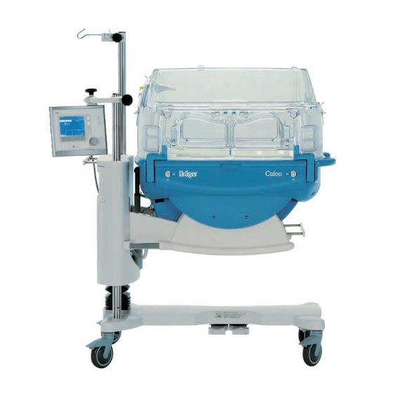
Dräger Caleo Instructions For Use Manual
Neonatal incubator
Hide thumbs
Also See for Caleo:
- Instructions for use manual (148 pages) ,
- Instructions for use manual (150 pages) ,
- Cleaning (7 pages)

Subscribe to Our Youtube Channel
Related Manuals for Dräger Caleo


Summary of Contents for Dräger Caleo
- Page 1 Caleo ® Neonatal Incubator WARNING To properly use this medical device, read Software 2.n and comply with these instructions for use. Instructions for Use...
- Page 2 Caleo, Twincubator, Kangaroo Mode, and ThermoMonitoring are registered trademarks of Dräger. BabyLink, Caleo Calmcapsule, Caleo CleanSwitch, Caleo SoftBed, Caleo JumboPorts, ThermoPad, and ThermoTrace are trademarks of Dräger. © 2000 - 2012 Dräger Medical GmbH All rights reserved, Subject to modifications...
- Page 3 How to use these Operating Instructions The headline ... Preparation specifies the subject of the main chapter Installing Accessories to help you find your way around quickly. Moving the control unit to the opposite side for 38 mm pole The page body ... Loosen clamping screw to remove control unit.
- Page 4 This page intentionally left blank...
- Page 5 Contents Important Safety Information Intended Use What’s What Operating Concept Preparation Checking Readiness For Operation Operation Care Maintenance Maintenance intervals Troubleshooting Theory of Operation Glossary Technical Data Ordering Information...
- Page 6 This page intentionally left blank...
- Page 7 Important Safety Information — Intended Use Important Safety Information ........8 Operator's Responsibility for Patient Safety .
- Page 8 Important Safety Information Operator's Responsibility for Patient Safety Definitions Important Safety Information Operator's Responsibility for Patient Safety Definitions WARNING ! WARNING ! Strictly follow these Instructions for Use A WARNING statement provides important information about a potentially hazardous situation which, if not Any use of the product requires full understanding and avoided, could result in death or serious injury.
- Page 9 We recommend obtaining a service contract benefits of using an infant incubator. with DrägerService. For repairs of the Caleo incubators we recommend that you WARNING ! contact DrägerService. Dräger cannot warrant or endorse the safe performance of third party accessories for use with the Caleo incubator system.
- Page 10 Important Safety Information Precautions During Preparation WARNING ! WARNING ! Always observe the maximum load of the infant bed (5 kg, 11 lbs). Always observe all precautions against fire hazards from oxygen (see page 61). WARNING ! WARNING ! Never leave infant unattended when the bed has been pulled out to avoid any risk of an infant falling out of an Never leave infant unattended when access doors or incubator.
- Page 11 A fault in any of the components in the link between containing sterilized distilled or demineralized water. nurse call and central hospital alarm system (e.g. in the electronics for nurse call in Caleo, in the Caleo power Do not use any additives for water intended for supply, or in the enunciator of the central hospital alarm humidifying the incubator.
- Page 12 Accessory equipment must not collide with the unit when adjusting tilt angle and height of Caleo. Accessory equipment on the handle side does not move CAUTION ! with the main unit during height adjustment of Caleo Maximum loads for pole extensions (Handle side, see page 170). –...
- Page 13 CAUTION ! The castor with direction lock does not have a brake. WARNING ! To secure Caleo, apply the brakes on all 3 castors with brakes. The infant’s central temperature must be regularly monitored with an independent thermometer.
- Page 14 WARNING! selected and controlled on the basis of the arterially measured oxygen partial pressure in the infant's blood Cleaning mode may only be used while Caleo is not (SaO or SpO ). This is the only way to minimize the risk occupied by a patient.
- Page 15 WARNING ! and current consumption limits! (See "Technical Data", page 166.) Caleo is to be used only in rooms with line power installations that comply with national safety standards for hospital patient rooms (e.g., IEC/EN 60601-1 "Medical WARNING ! Electrical Equipment - General Requirements For Safety").
- Page 16 The accessory equipment must not collide with the unit approved for use with Dräger Caleo. when adjusting the tilt angle and height of Caleo. Disposable sensors must not be cleaned for re-use. The accessory equipment on the handle side will not move...
- Page 17 Important Safety Information WARNING ! CAUTION ! Certain components of the Caleo incubator consist of Risk of burns upon contact with the heater. materials that are sensitive to certain organic solvents Allow Caleo to cool down before further disassembly. sometimes used for cleaning and disinfecting (e.g., alcohols, phenols, halogen releasing compounds, oxygen releasing compounds, strong organic acids, etc.).
- Page 18 The device must be inspected and serviced at regular 1 year intervals. A record must be kept on this preventive maintenance. We recommend obtaining a service contract with DrägerService. For repairs of the Caleo incubators we recommend that you contact DrägerService.
- Page 19 5 kg (11 lbs). Electrical Equipment - General Requirements For Safety"). Caleo is intended for use in clinical environments where premature babies or infants are treated who require a To maintain grounding integrity, connect only to a controlled climatic environment.
- Page 20 Intended Use Restrictions of Use WARNING ! General information on electromagnetic compatibility (EMC) according to the international EMC standard IEC 60601-1-2 Medical electrical equipment needs special precautions regarding electromagnetic compatibility (EMC) and needs to be installed and put into service according to the EMC information provided in the technical documentation available from DrägerService upon request.
- Page 21 What’s What / Operating Concept What's What ........... . . 22 Front View .
- Page 22 What's What Front View What's What Front View Canopy (2M 51 108) Access port Front door Transport handle Bassinet frame Drawer (2M 50 565)* Pedals for height adjustment* Height adjustable column*/ bassinet mount Connection for water heater (luer lock)* 10 X-ray drawer / slide-out bed 11 Display 12 Control unit 13 Upright mounting support...
- Page 23 What's What Side View, Connections Side View, Connections Central alarm light Sensor unit, temperature sensor connections Line power connection On/off switch Air intake filter cover connection for O control* Water container (2M 50 040)* Twin access U-grommets (2M 50 385) Side door 10 U-grommets (2M 50 412) 11 Feeding grommet, hood (2M 51 109)
- Page 24 What's What Top View Top View Leveling guides Heating air vents Connections* on the back of the Control Unit Nurse call MEDIBUS* Service RSB (Remote Service Box) Available option...
- Page 25 What's What Labels Labels Connections for skin temperature sensors, page 70 auxiliary power strip, page 51, Technical Data, Σ 2 A max. page 166 Type designation for T 2 H 250V IEC127-2/V fuses for auxiliary power strip Type designation for F 10A UL 248-14 system fuses Equipotential bonding...
- Page 26 What's What Labels Caleo Infant Incubator Quick Reference For detailed information, always refer to Caleo Operating Manual ! Before use, check device according to Instructions in Operating Manual. Switch on device (rear side of mobile stand). Select control mode by pressing button.
- Page 27 What's What Labels page 60 Never leave baby unattended when doors are open ! Do not tilt canopy forwards, page 43 page 24, page 153 WARNING! Never block or obstruct air vents! Risk of burning! page 45 Always close X-ray tray tightly ! page 170 max 5 kg, 11lbs...
- Page 28 What's What Labels Castor without brake function, page 47 Stop...
- Page 29 Operating Concept Control Unit Operating Concept Control Unit Hard keys (fixed function keys) 13 14 serve to allow the user to call various functions of the Caleo incubator: Scale* Bed tilt Menu list / configuration Menu Toggle key: air/skin temperature control...
- Page 30 Operating Concept Screen Screen By default, incubator parameters are displayed as numerical values (standard screen). – Setpoint and measured values for air temperature or skin temperature – Setpoint and measured values for relative humidity* – Setpoint and measured values for O concentration* –...
- Page 31 Preparation / Checking Readiness For Operation Preparation ........... . . 32 Before Using Incubator For the First Time .
- Page 32 Accessory equipment must not collide with the unit when adjusting tilt angle and height of Caleo. Accessory equipment on the handle side does not move with the main unit during height adjustment of Caleo (Handle side, see page 170). Accessory poles...
- Page 33 Preparation Installing Accessories Moving the control unit to the opposite side for 38 mm pole Loosen clamping screw to remove control unit. (Support control unit to prevent it from dropping once clamping screw is loosened.) Loosen clamping screw to remove holder. Upon delivery, the control unit is attached to the 38 mm dia.
- Page 34 Preparation Installing Accessories Infusion support attachment (2M 21 514) for 38 mm pole CAUTION ! Maximum load per hook is 3 kg (6.6 lbs). Slide pole clamp of the IV support onto the pole. Push the IV support hook into the attachment clamp and secure by firmly tightening the clamp knob.
- Page 35 Preparation Installing Accessories Compact mounting rail clamp (2M 85 337) for 38 mm pole CAUTION ! Maximum load for compact rail clamp is 5 kg (11 lbs). The compact mounting rail clamp may only be installed by qualified technical personnel. For mounting such accessories as: –...
- Page 36 Preparation Installing Accessories Instrument tray 3020 (M 24 678) CAUTION ! Maximum load for instrument tray is 2 kg (4.4 lbs). Hang tray from a standard (5 x 25 mm) rail on the wall or on the handle side and secure in position. Pole extensions The following poles can be attached to the base-mounted accessory pole as extensions:...
- Page 37 Preparation Installing Accessories Monitor support shelf (2M 50 085) The monitor shelf can be mounted on the wall side and/or the handle side. CAUTION ! Maximum load for monitor shelf is 20 kg (44 lbs). Do not exceed the maximum installation height. Vertical distance between monitor shelf and stand must not exceed 20 cm (7.8 inches) on the wall side and 100 cm (39 inches) on the handle side (see page 170).
- Page 38 Attach O analyzer to rail using the appropriate bracket. Place O sensor capsule inside Caleo. Route sensor cable through one of the flexible hood grommets. Securely connect sensor plug to O analyzer (see Instructions for Use of O analyzer being used).
- Page 39 Preparation Installing Accessories Installing a drawer (2M 50 565) CAUTION ! Maximum load for drawer is 7 kg (15 lbs). The drawer may only be mounted by qualified technical personnel! Mount as specified in the Installation Instructions. To install, slide drawer box into the groove in the base frame.
- Page 40 Preparation Use of Doors, Ports, and Bed Adjusting Mechanism Use of Doors, Ports, and Bed Adjusting Mechanism WARNING ! Never leave infant unattended when access doors or access ports are open to avoid any risk of an infant falling out of an incubator. Access ports To open access ports: Press down the ribbed area of the lever:...
- Page 41 Preparation Use of Doors, Ports, and Bed Adjusting Mechanism Lower front door until it hangs down vertically towards the floor. WARNING ! When opening and closing front door, avoid pinching or jamming hoses and cables in the attached double wall. To close front door: Raise the front door and press into position, Turn the two knobs outwards to the horizontal position until...
- Page 42 Preparation Use of Doors, Ports, and Bed Adjusting Mechanism Double wall* The double wall (2M 51 150) can only be fastened to the canopy (2M 51 108)! Fitting the double wall: Pull the pin up as far as it will go. The red section of the pin must be visible.
- Page 43 Hold the double wall with both hands and lift it off. Storing the double wall: Fix the holder (2M 51 152) to the compact rail of the Caleo. Hook the double wall with the pin to the holder. Note the set height of the Caleo. Make sure that if the Caleo is lowered the double wall does not touch the floor.
- Page 44 Preparation Use of Doors, Ports, and Bed Adjusting Mechanism To remove the canopy: Grasp handles on the sides of the canopy with both hands. Lift canopy horizontally off the supports. Re-installing the canopy: Place canopy horizontally, with the guide pins sliding into the holes in the canopy supports.
- Page 45 Feeding grommet, hood (2M 51 109) can only be used if a double wall is not attached to the canopy. Route cables, hoses, or tubes through the flexible grommets. To route ventilator circuits and cables through Caleo, use the ventilation circuit support arm (see page 37). optional equipment feature...
- Page 46 Preparation Use of Doors, Ports, and Bed Adjusting Mechanism Ventilation hose strain relieves* The ventilation hose strain relieves (2M 51 140) can only be attached to hose modules with pins (2M 51 139). Ventilation hose strain relieves act as guides for hoses and cables. Drainage module* The drainage module (2M 51 142) can only be mounted on the pillar elements (2M 51 154 and 2M 51 156).
- Page 47 (longitudinal axis of device). CAUTION ! The castor with direction lock does not have a brake. To secure Caleo, apply the brakes on all 3 castors with brakes. NOTE: The castor with direction lock is visually distinct from the castors with brakes.
- Page 48 Press button to raise bed on the control unit side. Press button to lower bed on the control unit side. The levels will indicate whether the bed is horizontal. Level showing the horizontal position of Caleo in the transverse axis. Level showing the horizontal position of Caleo in the longitudinal axis.
- Page 49 Bleed the transfer set (let sterilised water drain off). Close the clamp on the transfer set. Open the clamp on the transfer set. ® Switch on the humidification module on Caleo and set the humidity value (page 59). Water tank empty = Water shortage alarm is triggered on ®...
- Page 50 Bleed the transfer set (let sterilized water drain off). Close the clamp on the transfer set. Open the clamp on the transfer set. ® Switch on the humidification module on Caleo and set the humidity value (page 59). Replacing the water bag: Water bag empty = Water shortage alarm is triggered on ®...
- Page 51 Do not exceed the maximum permissible power input for connected accessories (all 4 sockets together: max. 2 A). Do not exceed the maximum permissible total leakage current. For the leakage current of Caleo without socket strip see "Technical Data", page 166.
- Page 52 WARNING! Connect nurse call to a central hospital alarm system only while Caleo is properly grounded via its power cable and a grounded wall outlet or via the grounding pin on the rear panel of the control unit.
- Page 53 A fault in any of the components in the link between nurse call and central hospital alarm system (e.g. in the electronics for nurse call in Caleo, in the Caleo power supply, or in the enunciator of the central hospital alarm , etc.) may result in failure of the nurse call.
- Page 54 Connect to line power supply. Check the nurse call system* prior to each use. Trigger an appropriate alarm, e.g. switch Caleo to skin temperature mode and remove the skin temperature sensors. If the nurse call system does not sound an alarm, take unit out of service.
- Page 55 Checking Readiness For Operation Before Each Use Before using the unit, make sure that the following tests as well as the checks described under "Before Reusing With a Patient", page 129, have been performed: Disinfect hands before each test! Check that access ports latch securely –...
- Page 56 Do not use the double wall. Take unit out of service. Check the bed tilting mechanism Tilt the bed. During the tilting process, the entire housing of the Caleo must move smoothly. Otherwise: Take unit out of service. WARNING ! Do not reach between incubator housing and housing support while tilting the bassinet.
- Page 57 Press both foot pedals in succession to raise and lower Caleo (see page 47). After the test, adjust to a comfortable working height. When adjusting the height, the entire Caleo bassinet must lift up and down smoothly, otherwise: Take unit out of service.
- Page 58 The opening screen is displayed. If no opening screen appears on the display: Take unit out of service. The unit is now switched on. WARNING! The Caleo incubator is ready for operation only when all checks have been performed successfully.
- Page 59 Switching Caleo On ........
- Page 60 The infant’s central temperature must be regularly The castor with direction lock does not have a brake. monitored with an independent thermometer. To secure Caleo, apply the brakes on all 3 castors with brakes. WARNING ! It is the responsibility of the attending physicians to...
- Page 61 When treating larger babies, their higher caloric output may eyes by retrolental fibroplasia) and hypoxemia (which cause the air temperature in the Caleo incubator to rise. In might contribute to intraventricular hemorrhage and this case, the double wall should be removed.
- Page 62 Only use phototherapy units supplied with their own stand. the working area. Do not place phototherapy devices directly on Caleo canopy, Do not mechanically load the cable by, for example, hanging as they may slip when the bed tilt is activated.
- Page 63 Caleo! Electrical safety WARNING ! Caleo is to be used only in rooms with line power installations that comply with national safety standards for hospital patient rooms (e.g., IEC/EN 60601-1 "Medical Electrical Equipment - General Requirements For Safety").
- Page 64 Operation Switching Caleo On Switching Caleo On Connect unit to line power. To switch unit on, press the on/off switch until it engages. Position control unit so that its screen is clearly visible from the working area. An audible alarm is emitted.
- Page 65 The display returns to the standard screen. The previous setpoint is retained. – Wait for 7 seconds: Caleo emits 4 short beeps to prompt the user to press the rotary knob. The display will immediately return to the standard screen. The previous setpoint will be...
- Page 66 Operation Using Air Temperature Control Using the extended air temperature setpoint range If the standard setpoint range is exceeded: – The advisory message »confirm extended range with rotary knob« will appear at the top of the screen. Press rotary knob to activate extended range. Turn rotary knob clockwise to increase setpoint further.
- Page 67 Operation Using Air Temperature Control If the specified setpoint is below the standard setpoint range: – The advisory message »confirm extended range with rotary knob« appears on screen. Press rotary knob to activate extended range. Turn rotary knob counterclockwise to decrease set value further.
- Page 68 The screen returns to the standard display mode and the former setpoint is retained. – Wait for 7 seconds: Caleo emits 4 short beeps to prompt the user to press the rotary knob. The display will immediately return to the standard screen. The previous setpoint will be retained.
- Page 69 The measured value starts flashing, The red bar LED starts blinking. The audible alarm can be silenced for 5 minutes. Caleo heats up if necessary to reach the specified interior air temperature setting. The measured value continues to flash, The red bar LED continues to flash.
- Page 70 Operation Using Skin Temperature Measurement Using Skin Temperature Measurement Checking proper function of the temperature sensors Immediately before using the yellow skin temperature sensor or the white peripheral sensor, insert it into the yellow or white socket, respectively, and wait for a measurement signal to appear on screen.
- Page 71 Use only Dräger sensors or sensors authorized by Dräger for use with Caleo. WARNING ! Always verify that temperature sensors are specified and approved for use with Dräger Caleo. Disposable sensors must not be cleaned for re-use. If used more than once, the necessary measurement precision cannot be guaranteed.
- Page 72 WARNING ! Skin temperature control mode must not be used on twins, since Caleo controls only the temperature for one infant. Risk of hypothermia or overheating. Always use air temperature control mode when caring for twins.
- Page 73 Operation Switching Between Air and Skin Temperature Control Press key to change temperature control mode. The LED for the control mode will start blinking, thereby requesting confirmation of the mode change. – The activated control mode is displayed on screen. Actual, measured value, and setpoint are displayed as bar graphs and numeric values.
- Page 74 The display returns to the standard screen. The previous setpoint is retained. – Wait for 7 seconds: Caleo emits 4 short beeps to prompt the user to press the rotary knob. The display will immediately return to the standard screen. The previous setpoint will be...
- Page 75 WARNING ! Skin temperature control mode must not be used on twins, since Caleo controls only the temperature for one infant. Risk of hypothermia or overheating. Always use air temperature control mode when caring for twins.
- Page 76 Operation Using Skin Temperature Control Adjusting the setpoint Standard setpoint range C to 37 Extended setpoint range 37.1 C to 38 Default setting 36.5 Press key to adjust setpoint. – The actual measured value and setpoint are displayed on screen both as bar graphs and as numerical values. –...
- Page 77 The display returns to the standard screen. The previous setpoint is retained. – Wait for 7 seconds: Caleo emits 4 short beeps to prompt the user to press the rotary knob. The display will immediately return to the standard screen. The previous setpoint will be retained.
- Page 78 The screen returns to the standard display mode and the previous setpoint is retained. – Wait for 7 seconds: Caleo emits 4 short beeps to prompt the user to press the rotary knob. The display will immediately return to the standard screen. The previous setpoint will be retained.
- Page 79 As long as 3 dashes remain on screen while the incubator is operated in skin temperature control mode, Caleo will not heat. Infant may become hypothermic. The numerical values in this description are examples. See "Configuring alarm settings", page 107.
- Page 80 As long as 3 dashes remain on screen while the incubator is operated in skin temperature control mode, Caleo will not heat. Infant may become hypothermic. The alarm tone can be silenced for 5 minutes: Press key to silence intermittent audible alarm, press rotary knob.
- Page 81 Operation Using Humidity Control Using Humidity Control* Connect the humidifier system (see "Using Humidification Systems", page 49). Press key to set humidity control. The actual value and current setpoint of the humidity control are displayed as bar graphs and numerical values. Soft key symbols: = New setpoint has not been activated.
- Page 82 Turn rotary knob counterclockwise to decrease setpoint. Press rotary knob to confirm setpoint. The maximum humidity reached depends on air temperature and ambient humidity. At high air temperature or low ambient humidity, the maximum humidity level that can be reached inside Caleo will be reduced.
- Page 83 Operation Using Humidity Control – Current measured value and setpoint for controlling humidity are displayed as bar graphs and numerical values. – The display returns to the standard screen. Measured values and setpoints are displayed.
- Page 84 Operation Using Humidity Control Alarms In the event of an empty water supply – A message »Water empty, please refill« appears on screen. – An alarm tone sequence (3 beeps) starts, – The central alarm indicator lights up*, The measured value starts flashing, The yellow bar LED starts blinking.
- Page 85 – Open valves on O cylinders slowly. – Do not operate Caleo in the presence of flammable anesthetics or disinfectants. Risk of explosion! – Do not use or store flammable liquids such as alcohol, ether, or acetone inside the Caleo incubator.
- Page 86 Operation Using O2 Control – The measured value and current setpoint for O control are represented by bar graphs and numerical values. Soft key assignments: = New settings are not activated. = Switch off O control. = Switch on O control.
- Page 87 Operation Using O2 Control – The display returns to the standard screen. Current measured values and setpoints are displayed. If value to be set exceeds the standard range: – The following message is displayed at the top of the screen »confirm extended range with rotary knob«.
- Page 88 Operation Using O2 Control – The display returns to the standard screen. The measured values are displayed. – The setpoint and »set: >40 « are displayed alternately. – The yellow bar LED lights up. If the yellow bar LED starts flashing, the setpoint has been increased by more than 3 % or 5 % (see page 88), or other alarms are active.
- Page 89 4 different brightness levels. Upon starting the incubator, the screen is displayed with maximum brightness. After restarting Caleo, e.g. after a power failure, the screen is displayed in the mode last selected. – The softkey for Day and Night mode is designated on the...
- Page 90 NOTE: In Kangaroo Mode the incubator is always operating in air temperature control mode. If Caleo was previously operating in air temperature mode, the air temperature setpoint will remain active while in Kangaroo Mode. If Caleo was previously operating in skin temperature mode, the average of the last 3 minutes of air temperature values will be used as setpoint.
- Page 91 Operation Selecting Menus The previously set values for – Humidity (page 82) and – (page 86) are retained in Kangaroo Mode. The previous set value for skin temperature control is stored in buffer memory. Activating Kangaroo Mode For a description of Kangaroo Mode, see page 156. Press »menu«...
- Page 92 Operation Selecting Menus Tubing grommets can be removed from the corner segments of the hood so that hoses and cables connected to the infant remain well organized during Kangaroo Mode. Alarms Alarm limits can be changed in the configuration (see page 107). If the skin temperature of the yellow skin temperature sensor (skin 1) falls below the alarm limit set in the configuration: –...
- Page 93 To maintain Kangaroo Mode = press » « key. – Wait for 7 seconds: Caleo emits 4 short beeps to prompt the user to press rotary knob. The display will immediately return to the standard screen. The previous setpoint will be retained.
- Page 94 Operation Selecting Menus Trend display The display of trends serves to graphically and numerically illustrate measured parameters. The data window shows the most recent data in the selected time interval. In addition, the current measured values and setpoints are displayed. Switching between standard and trend screen Press »...
- Page 95 Operation Selecting Menus Select the desired trend display from the displayed list. Defaults: – Air temperature trend – Zoom factor: 3 hours Turn rotary knob to select trend. Press rotary knob to activate trend. Press » « key to return to menu selection. Press »...
- Page 96 Operation Selecting Menus Press key to display zoom menu. Select desired zoom factor from the menu. Turn rotary knob to select zoom factor. Press rotary knob to activate zoom factor. Press » « soft key to return to menu selection. Press »trend«...
- Page 97 Operation Selecting Menus Trend analysis Trend analysis is used for graphically and numerically displaying measurement parameters and associated setpoints. The data time window can be moved freely across the last 7 days. Trend analysis can therefore be used to evaluate thermo-moni- toring data.
- Page 98 Operation Selecting Menus – The trend graph for the selected measured value is displayed on screen. Default measured value: trend 1 Skin temperature trend 2 Air temperature zoom 3 hours The selected value is displayed as a trend graph. In this graph, the trend curve of the measured value is overlaid on the corresponding setpoint curve.
- Page 99 Operation Selecting Menus Trend selection A trend graph may be selected with soft keys. Soft key assignments: = Cancel. New settings will not be activated. trend 1 = Select trend 1 trend 2 = Select trend 2 zoom = Select time interval To select trend 1: Press soft key to display trend 1 menu.
- Page 100 Operation Selecting Menus The newly selected trend is displayed on the screen below trend 1. In addition, a second data window containing the respective numerical parameters is opened next to trend 2. Time cursor and time range (zoom) are the same for both trend displays.
- Page 101 Alternatively, if no key is pressed for 2 minutes, the display will automatically revert to the standard screen. Cleaning mode* WARNING! Cleaning mode may only be used while Caleo is not occupied by a patient. – Cleaning mode is only available if Caleo is equipped with humidity control.
- Page 102 Operation Selecting Menus Press »menu« key to display the main menu. Select "Cleaning Mode" from the displayed menu. Turn rotary knob to select item. Press rotary knob to confirm (activate) item. – The required operating steps are specified on screen: »disconnect Luerlock connector from apparatus make sure that no patient is inside start Cleaning Mode by...
- Page 103 A screen message will indicate when the cleaning procedure has been completed. Press rotary knob to confirm end of cleaning mode. Caleo performs a restart. After ending Cleaning Mode: – Disinfect and clean Caleo (see "Disinfecting / Cleaning / Sterilizing", page 118).
- Page 104 Operation Configuration Configuration In configuration mode, you may set: – language, date, and time, – system parameters, and – alarm parameters. Additionally, information may be obtained on: – sensors, and – the software version. Activating configuration mode Hold down »menu« key for 4 seconds to display configuration mode.
- Page 105 Operation Configuration Configuring language/date/ time Turn and press rotary knob to select language/date/time. – The language selection is highlighted by a bold frame. Turn rotary knob to select language. Press rotary knob to confirm language. – The selected language is displayed on screen. Follow the same procedure to set the date format, date, and time.
- Page 106 , central alarm indicator, eleva- tion above sea level, and contrast are configured in the same fashion. – The unit of weight can only be configured if Caleo is equipped with the integrated infant scale*. – When using two skin temperature sensors, T...
- Page 107 Operation Configuration Configuring alarm settings From the configuration mode selection menu: Turn and press rotary knob to configure alarms. – The menu that is then displayed allows the user to select Kangaroo Mode alarm settings, the initial volume of audible alarms and the alarm thresholds for temperature control and control.
- Page 108 Operation Configuration Audible alarm volume: Setpoint range: 1 to 8 Default: – The initial alarm volume is highlighted by a light background. Turn rotary knob to set audible alarm volume default to be in effect at start-up. Press rotary knob to confirm initial volume setting. The screen returns to the alarm settings menu (page 107).
- Page 109 Operation Configuration Viewing O sensor information* From the configuration mode selection menu: Turn and press rotary knob to select "O sensor information". The screen displays the following information for the sensors used: – Date of manufacture – Date of last calibration –...
- Page 110 Operation Keypad Lock Keypad Lock Locking keypad Press key to prevent any on-screen setting. The LED in the key lights up. – After 4 seconds, all screen functions are locked, except for: Keypad lock Alarm silencing Rotary knob Bed tilt. The LED in the key remains lit.
- Page 111 Operation Suppressing Alarms Suppressing Alarms When pressing this key while an alarm is active: – The audible alarm is silenced. – The central alarm indicator goes out.* The LED in the button is not lit. The maximum duration for suppressing an alarm depends on the type of the alarm.
- Page 112 It is suggested that weighing should only be conducted when the trolley castors on Caleo are locked. This helps to cushion vibrations and increases the accuracy of weight measurements.
- Page 113 Technical Data is only attained if the scales are calibrated at the installation location. Preparing for weighing Set Caleo to the horizontal position. Check with the aid of the built-in levels – see page 48. Remove all objects that touch both the bed and the fixed environment or the incubator frame.
- Page 114 Operation Integrated Infant Scale During weighing, the user is guided through the sequence of operating steps by the following prompts. Lift the baby off the bed. The system waits until the scale has stabilized and has been at rest for 3 seconds. –...
- Page 115 Preparing for weighing Set Caleo to the horizontal position. Check with the aid of the built-in water levels – see page 48. Set both knobs to the horizontal position see page 45.
- Page 116 The screen displays the last weight as advisory text for the next 10 minutes. End of Operation Before turning off Caleo, acknowledge all active alarms with high risk potential. Otherwise the nurse call system* will continue to indicate the active alarm after the device has been switched off.
- Page 117 Care / Maintenance / Disposal Care ............118 Precautions .
- Page 118 Care Precautions Disinfecting / Cleaning / Sterilizing Care Precautions Disinfecting / Cleaning / Sterilizing The Caleo incubator system must be thoroughly cleaned and Testing of procedures and agents disinfected – after each patient Due to material incompatibilities, preparations based on –...
- Page 119 Risk of burning when touching the heater! When the incubator is closed, the heater is still hot enough to cause serious burns for a long time after switching off (still approx. 70 oC after 1 hour). Allow Caleo® to cool down sufficiently before stripping it down.
- Page 120 Care Testing of procedures and agents Disinfect and clean accessories such as the aspiration unit in accordance with their specific Instructions for Use. Water heater The water heater does not have any components that must be dismantled for the preparation. Execute the Cleaning Mode after each change of patient.
- Page 121 Care Disassembly Disassembly Checking the air intake filter Tilt the unit (see page 48) for easy removal of the air intake filter. Check expiration date: see label on the unit. Press down the knurled part of the clip and open the filter cover.
- Page 122 (200 F)*, sterilize at 134 C (273 F)*. Tilt Caleo bassinet back to the horizontal position (see page 48). Switch on cleaning mode** (see page 101). Observe national and international standards regarding procedures for cleaning, disinfection, and sterilization. Available option...
- Page 123 WARNING ! Risk of burns upon contact with the heater. Allow Caleo to cool down before further disassembly. Removing the double wall Pull the pin up as far as it will go. The red section of the pin must be visible.
- Page 124 Care Disassembly Tilt the sleeve to one side and pull it out. Tilt the centring lugs to one side and pull them out. Remove obvious soiling with a disposable cloth. Wipe-disinfect the double wall surfaces. After allowing disinfectant to take effect (see manufacturer's directions for prescribed exposure times), wipe surfaces with a clean, damp, disposable cloth, then rub dry.
- Page 125 Care Disassembly Open front doors Turn the two locking knobs inwards as far as they will go and fold down the front door. Fold out the hinged double walls to clean them. Open the side doors in the same way. Remove visible soiling with a disposable cloth and detergent.
- Page 126 Care Disassembly Mattress and bed Remove mattress from bed. Remove bed. CAUTION ! Take care not to damage the sensor unit when removing patient bed. Remove visible soiling with a disposable cloth and detergent. Wipe-disinfect all surfaces. After allowing disinfectant to take effect (see manufacturer's directions for prescribed exposure times), wipe surfaces with a clean, damp, disposable cloth, then rub dry.
- Page 127 Care Disassembly Lift trough out. Remove fan. Remove visible soiling with a disposable cloth and detergent. Wipe-disinfect all surfaces. After allowing disinfectant to take effect (see manufacturer's directions for prescribed exposure times), wipe surfaces with a clean, damp, disposable cloth, then rub dry. Turn trough over.
- Page 128 Care Disassembly Control unit Pull rotary knob from the control unit. Remove visible soiling with a disposable cloth and detergent. Wipe-disinfect the surfaces. After allowing disinfectant to take effect (see manufacturer's directions for prescribed exposure times), wipe surfaces with a clean, damp, disposable cloth, then rub dry. CAUTION ! Do not allow any moisture to enter the control unit.
- Page 129 Care Before Reusing With a Patient Before Reusing With a Patient Check that the system has been cleaned and disinfected in conformity with all applicable hospital protocols. Reassemble the equipment with disinfected hands. Reassemble all equipment and re-install accessories, see "Disassembly", page 121. NOTE: When inserting the trough, make sure that both latches snap in place.
- Page 130 Care Before Reusing With a Patient Assembling the double wall Check parts for damage and replace if necessary. Fit the parts into the double wall. Fit in the following order: Sleeve Centring lugs Seal Insert the drainage module* into the pillar element Check the parts for damage and replace if necessary.
- Page 131 Care Before Reusing With a Patient Check that access ports latch securely – Perform this test on all 4 access ports Press down the ribbed area of the lever to open access port. Close access port until lever engages in the locked position. Try to open the access port by pulling it outwards by its edge –...
- Page 132 Care Before Reusing With a Patient Check that the side door latches securely – Perform this test on both side doors Open side door slightly. Then, push door back into its closed position. Turn the two knobs outwards until they tangibly engage in the horizontal position.
- Page 133 Care Before Reusing With a Patient Check all four corners of the canopy for any damage to the hinge. Tilt canopy up slightly, and check canopy prop. Lower canopy back. – Perform check from both sides. If canopy does not open and close properly: Take unit out of service.
- Page 134 To remove possible disinfectant residues, we recommend running the incubator in standby mode. Switch on Caleo (see page 64). Activate air temperature control (see page 65). Run Caleo at 37 C with opened access ports.
- Page 135 Care Care List Care List Applicable to non-infectious patients. The list contains approximate values only. The instructions of the hospital’s infection control officer shall prevail and must be observed by the user! What How often Disinfect and clean Sterilize Reusable components Care intervals Wipe Cleaning and...
- Page 136 Maintenance intervals Maintenance intervals This chapter describes the required maintenance measures to ensure correct functioning of the medical device. These measures should be performed only by maintenance personnel. CAUTION ! Disinfect and clean the incubator or the relevant parts before each maintenance operation, even when returning the equip- ment for repair purposes! CAUTION !
- Page 137 Maintenance intervals Safety checks – Fuses accessible from outside match the specified values Check the equipment of the medical device fully in accordance with the Instructions for Use. Check electrical safety conforming to IEC 62353. Check safety systems Check the incubator temperature: –...
- Page 138 Maintenance intervals Maintenance Maintenance CAUTION ! This device must be inspected and serviced at manufacturer- specified intervals. The following table shows the maintenance intervals: Interval times Who? when weekly every every once every necessary 2 months 6 months a year two years Replaceable parts: Fresh air filter...
- Page 139 Disposal Maintenance Disposal Disposal of the water supply connection kit and air intake filter – with household waste. Disposal of O sensors and batteries WARNING ! Treatment of batteries and O sensors – Do not throw into fire! Risk of explosion. –...
- Page 140 This page intentionally left blank...
- Page 141 Troubleshooting Troubleshooting – Error Messages ........142 Troubleshooting –...
- Page 142 Troubleshooting Troubleshooting – Error Messages Troubleshooting Troubleshooting – Error Messages All error messages are displayed on screen. They are listed below in alphabetical order. See also "Alarm Description", page 161. Message Cause Remedy Audible alarm silence Adjust. inoperable Height adjustment faulty. Take unit out of service.
- Page 143 Troubleshooting Troubleshooting – Error Messages Message Cause Remedy Audible alarm silence Connect skin 1 sensor Probe for skin temperature (yellow) Check connection and correct if 5 min not connected. necessary. Three dashes flashing on screen in place of the measured value. Red bar LED on the control unit starts blinking.
- Page 144 Troubleshooting Troubleshooting – Error Messages Message Cause Remedy Audible alarm silence Humidity sensor inoperable Faulty humidity sensor. Switch off humidity module. 1 min 3 flashing dashes on the screen. Take unit out of service. Red bar LED on the control unit starts blinking.
- Page 145 Troubleshooting Troubleshooting – Error Messages Message Cause Remedy Audible alarm silence Oxygen valve fault valve faulty. Switch off O module. 1 min Measured value starts flashing on screen. Take unit out of service. Yellow bar LED flashes on control unit. Central alarm indicator lights up.* Intermittent audible alarm (3 beeps).
- Page 146 Troubleshooting Troubleshooting – Error Messages Message Cause Remedy Audible alarm silence Skin 1 temperature below 36.0 Kangaroo Mode alarm: Increase heat supply to the infant. 15 min (see "Configuration", page 107) Skin temperature is falling below the Check configuration. alarm limit. Measured value starts flashing on screen.
- Page 147 The yellow LED in the alarm button Alarm suppression is active. Deactivate alarm suppression. is lit. If any other faults not listed in this table occur, or in case Caleo does not respond as expected: Take unit out of service.
- Page 148 This page intentionally left blank...
- Page 149 Bed and Mattress ..........151 ® Twins in the Caleo (Caleo Twincubator ) ......151 Taking X-Rays .
- Page 150 Accessibility Caleo provides excellent accessibility to the infant for all regular and intensive care activities: for this purpose, the four access ports (two on each longitudinal side) have been designed with especially large dimensions ™...
- Page 151 Twins in the Caleo (Caleo Twincubator ® Twins can be placed together in Caleo if there are no medical objections and if their total combined weight does not exceed 5 kg. When treating twins in a single incubator, Caleo must be operated in air control mode.
- Page 152 The infant scale in the Caleo comprises four weighing cells located underneath the bed, an electronic measuring and analysis unit and a special page on the control monitor. In normal mode, the entire bed rests on these four weighing elements under the bed.
- Page 153 If the setpoint is lower than the actual measured air temperature, the heater receives the signal to apply less heat. The air temperature inside Caleo drops. If the current air temperature deviates from the set value by more than ±1.5...
- Page 154 ThermoMonitoringTM Caleo temperature control characteristics The desired temperature increase is achieved rapidly due to the high heating power of Caleo. Lowering air temperature takes longer, due to the good thermal insulation of the incubator. Note on setting air temperature setpoint for Caleo: Inside the incubator, the infant has limited –...
- Page 155 (if the skin is too cold) or the more the air temper- ature in Caleo is reduced (if the skin is too warm). Wait for the controller to reach steady state.
- Page 156 Other Caleo features designed to ensure easier removal of the infant from Caleo for "kangarooing": –...
- Page 157 In order to perform this monitoring with as little nuisance alarms as possible to mother/father and infant, Caleo allows to activate special Kangaroo Mode alarms during operation in Kangaroo Mode. These alarms are set in the configuration. The following alarm limits are set: –...
- Page 158 Theory of Operation O2 Therapy ΔT max.: This alarm is triggered if the difference between Skin T1 and Alarm deactivated °C Skin T2 is greater than this alarm threshold (risk of hypo- thermia). Skin T 1 ∆T >4 °C Skin T 2 t (min) Alarm activated Each of these alarms can either be set or switched to "OFF"...
- Page 159 Theory of Operation Humidity Control Humidity Control Caleo provides a means for hygienic humidification of the incubator air by evaporating (boiling) water from a separate supply (water bag or water reservoir). With closed-loop humidity control, only the desired relative humidity setpoint is entered, and Caleo then automatically controls the evaporator output of the humidifier to maintain the preset relative humidity in the patient capsule.
- Page 160 As a safety precaution, any non-permissible operating condition will cause Caleo to switch off its main heater or water heater, respectively. An additional temperature sensor in the warm air vent limits heater output in cases where the heater control would generate maximum output over an extended period of time.
- Page 161 Red bar LED Yellow bar LED Red power failure LED next to the symbol Caleo distinguishes between 5 different alarm priorities that are accompanied by audible alarms: Serious device faults Device fault: Continuous audible alarm that cannot be silenced, and red bar LED lighting up.
- Page 162 Theory of Operation Alarm Description Information No bar LED lit, no audible alarm. For example: – Humidity deviation above 10 % Information messages regarding the active alarm are displayed on screen. If another alarm occurs while an audible alarm is silenced, the audible alarm will be reactivated.
- Page 163 Glossary Key to Symbols Used Glossary Key to Symbols Used Alarm silence/suppression Cancel, stop setting procedure Weighing scale Bed tilt Bed can be pulled out Radioscopy, x-ray drawer can be pulled out Caution: please note special information on this function in the User Instruction Manual (this document).
- Page 164 This page intentionally left blank...
- Page 165 Technical Data / Ordering Information Technical Data ..........166 Ambient Conditions .
- Page 166 Technical Data Ambient Conditions Operating Data Technical Data Ambient Conditions Normal operation Temperature C to 35 C (59 F to 95 Air pressure 600 hPa to 1060 hPa Rel. humidity 10 to 95 % without condensation Storage / transport Temperature –20 C to 60 C (–4...
- Page 167 Technical Data Performance Data Measurement and Control Parameters Performance Data Warm-up time 20 minutes from 20 C to 31 C (at 20 C ambient temperature) Increase in O concentration from 21 to 60 vol.% <10 min Humidification Evaporation of sterile distilled or demineralized water Air speed over the bed <8 cm/second (3.1 inch/second) Fresh air flow...
- Page 168 Maximum humidity attained depends on air temperature and ambient humidity. With high ambient air temperature and low ambient humidity, respectively, the maximum humidity that can be reached inside Caleo will decrease. The measuring accuracy depends on the geological and geographical conditions at the installation site. Calibration before delivery is not sufficient...
- Page 169 Technical Data Physical Characteristics Nurse call (optional) Output for connection to in-house P.A. systems (nurse call) Connection 3 to 5 will be closed and the nurse call is activated in the event of an alarm with a high risk potential or if there is a serious equipment fault.
- Page 170 Technical Data Physical Characteristics Overview of max. loads 38 mm pole, max. 11 lb per pole 38 mm pole, max. 22 lb per pole 25 mm pole, max. 6.6 lb per pole 25 mm pole, max. 6.6 lb per pole max.
- Page 171 Incubator and Accessories Ordering Information Incubator and Accessories Designation and description Part No. Caleo 2M 50 555 / Caleo incubator with air and skin servo 2M 50 000 ® modes, ThermoMonitoring (temperature probes optional). With large front and rear access doors, ™...
- Page 172 Phototherapy 4000 (110-127 V) 2M 21 700 Stand for phototherapy unit 4000 2M 21 190 Accessories for care Cally 2M 30 462 “Caleo” incubator hood 2M 30 467 Upgrade kits 2M 50 900 Servo controlled humidity 2M 50 735 Servo controlled oxygen...
- Page 173 Cap for water reservoir 2M 50 042 Nozzle for water reservoir 2M 50 039 Infusion sets Caleo (20 pcs) MX 17 018 Caleo air intake filter (20 pcs) MX 17 015 ™ ThermoTrace , central (set of 5), yellow MX 11 000 ™...
- Page 174 This page intentionally left blank...
- Page 175 Before using for the first time ..... . 54 Twins in the Caleo® ......151 X-raying .
- Page 176 Index Front door ....... . 40 O2 analyzer ........38 Front view .
- Page 177 Index Setting time interval (zoom) ....95 Troubleshooting ....... 142 Error messages .
- Page 178 These Operating Instructions apply only ® to Caleo with Serial No.: If no Serial No. has been filled in by Dräger, these Operating Instructions are provided for general information only and are not intended for use with any specific machine or device.
Need help?
Do you have a question about the Caleo and is the answer not in the manual?
Questions and answers