Sign In
Upload
Manuals
Brands
Ricoh Manuals
All in One Printer
B064 SERIES
Ricoh B064 SERIES Manuals
Manuals and User Guides for Ricoh B064 SERIES. We have
5
Ricoh B064 SERIES manuals available for free PDF download: Service Manual
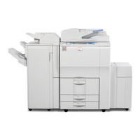
Ricoh B064 SERIES Service Manual (1465 pages)
Brand:
Ricoh
| Category:
All in One Printer
| Size: 58.19 MB
Table of Contents
Table of Contents
13
B064 Series/B140 Series
5
Table of Contents
13
Laser Safety
34
Troubleshooting
37
B246 Series/D052 Series
41
Installation
41
Installation Requirements
41
Operating Environment
41
Machine Level
42
Minimum Space Requirements
43
Dimensions
44
B064 Series
44
B140 Series
45
Peripheral/Option Summary Table
47
Power Requirements
50
Accessory Check
51
Installation Procedure
52
Removing Tapes and Retainers
52
Connecting the ADF
54
Removing and Filling the Development Unit
55
Re-Installing the Development Unit
57
Initializing the Drum Settings (B064 Series)
58
Initializing the Drum Settings (B140/B246/D052 Series)
59
Tandem Tray
60
Date/Time Setting
62
Machine Level
62
SP Codes
62
A3/Dlt Feeder Kit (B475)
63
Accessory Check
63
Installation Procedure
64
Lct (B473)
66
Accessory Check
66
Installation Procedure
67
Removing Tape
67
Installing the LCT
68
Preparing the Main Machine
68
Lg/B4 Feeder Kit (B474)
70
Accessory Check
70
Installation Procedure
71
3000-Sheet Finishers (B468/B469/B674)
74
Accessory Check
74
Installation Procedure
75
Removing Tapes and Retainers
75
Installation
77
Enabling Booklet Binding
80
Selecting the Staple Supply Name
80
Accessory Check
81
Punch Unit (B377)
81
Installation Procedure
82
Cover Interposer Tray (B470)
84
Cover Interposer Tray (B470)
85
Installation Procedure
85
Removing Tapes and Retainers
85
Attaching the Extensions
86
Attaching the Interposer Tray
87
Attaching the Corner Plates for the B478/B706
88
Right Rear Corner Plate (B478/B706 Only)
88
Right Front Corner Plate (B478/B706 Only)
89
Attaching the Finisher to the Machine
90
9-Bin Mailbox (B471)
92
Accessory Check
92
Installation Procedure
93
Installation
93
Removing Tapes and Retainers
93
Sheet Finisher (B478/B706)
95
Accessory Check
95
Installation
96
Moving the Finisher to a New Location
98
Punch Unit (B531/B812)
99
Accessory Check
99
Installation
100
Jogger Unit (B513)
104
Accessory Check
104
Installation Procedure
105
Z-Folding Unit (B660)
106
Z-Folding Unit (B660)
107
Installation Procedure
107
Before You Begin
107
Unpacking
108
Docking to the Finisher
109
Docking to the Main Frame
112
2000/3000 Sheet Finishers (B700/B701)
115
Installation Procedure
115
Removing Tapes and Retainers
115
Docking the Finisher
118
Attaching the Trays
121
Leveling the Finisher
122
Enabling Booklet Binding (B700 Only)
123
Selecting the Staple Supply Name
123
Auxiliary Trays
124
Punch Unit (B702)
126
Accessories
126
Installation Procedure
127
Cover Interposer Tray (B704)
130
Installation Procedure
131
Preparing the Finisher (B700/B701/B706)
132
Attaching the Extensions for the B706
133
Prepare the Cover Interposer for the B706
134
Attach the Extensions to the B706
135
Attaching the Extensions for the B700/B701
136
Attaching the Interposer Tray (B700/B701/ B706)
137
Attaching the Corner Plates for the B706
138
Docking the Finisher and Interposer to the Machine (B700/B701/B706)
140
Output Jogger Unit (B703)
143
Installation Procedure
144
Mail Box (B762)
146
Installation Procedure
147
Copy Tray (B756)
150
Installation
151
Key Card Bracket (B498), Key Counter Bracket (B452)
154
Key Counter Bracket B452 Accessories
155
Installation
156
Install the Key Card Bracket and Assembled Key Counter
157
Copy Connector Kits
159
Accessory Check
160
Installation
161
Installing the Hardware
162
Copy Connector Kit (B328-03) for B140 Series
166
Preparation
167
Installation
168
Copy Connector (B842) for B246/D052 Series
171
Preparation
172
Installation
173
Mfp Options: B064 Series
176
Installation Procedure
177
Installation Procedure
178
Ps3 (B525-08)
180
Usb 2.0 (B525-01)
181
USB SP Settings
182
Ieee1394 (G561) Firewire Interface
183
Installation Procedure
184
UP Mode Settings for IEEE 1394
185
SP Mode Settings for IEEE 1394
186
Ieee802.11B Wireless Lan (G628)
187
Installation Procedure
188
UP Mode Settings for Wireless LAN
189
SP Mode Settings for 802.11B Wireless LAN
191
File Format Converter (Mlb) (B519)
192
Accessory Check
193
Installing the Hardware
194
Merging Applications on One Sd Card
195
Merging Applications
196
Undo Exec
197
Storing Copied SD Cards on Site
198
Overview
199
Printer/Scanner Kit (B659)
200
Installation
201
Ps3 (B525-15)
204
Usb 2.0 Interface Board (B596-01)
205
Ieee 1394 Interface Board (B581-01)
206
Ieee 802.11B Interface Board (B582-01, -02)
207
Bluetooth Interface Unit (G377)
209
File Format Converter (B609)
210
Data Overwrite Security Unit (B735)
211
Seal Check and Removal
212
Installation Procedure
213
Mfp Options: B246/D052 Series
216
Common Procedures
217
Printer Scanner Kit (B841/D406)
218
Installation
219
Postscript3 (B525)
222
Ieee1394 Interface Board (B581)
223
Wireless Lan G813 (802.11B)
224
Bluetooth Interface Unit Type C B826
225
Accessory Check
226
Check the Accessories and Their Quantities against this List
226
Description Q'ty
226
File Format Converter Type C B609
226
Data Overwrite Security Unit Type C B735
227
Seal Check and Removal
228
Installation Procedure
229
Remote Communication Gate Type Cm1 (B818)
232
Installation
234
Usb Host Interface Unit Type a (B825)
235
Browser Unit Type B (B828)
236
Copy Data Security Unit Type C (B829)
237
VM Card (B861)
239
Ieee1284 B679
240
Gigabit Ethernet G381
241
Fax Option Type 7500 (B819)
242
Installation Procedure
243
Component Check
256
Installation Procedure
257
Preventive Maintenance
267
Optional Peripheral Devices
271
Sheet Finisher with 50-Sheet Stapler and Saddle-Stitching B468/B469/B674
272
Sheet Booklet Finisher B700/B701
273
Replacement and Adjustment
277
Transfer Belt Unit
278
Charge Corona
279
Cleaning
280
Special Tools and Lubricants
281
Operation Panel and External Covers
282
Right Covers
283
Left Covers
284
Rear Covers
285
Scanner
286
Top Covers
287
Exposure Glass
288
Scanner Original Size Sensors
289
Lens Block
290
Exposure Lamp
291
Lamp Regulator
292
Scanner Motor Drive Board (Sdrb)
293
Scanner Motor
294
Scanner Hp Sensor
295
Scanner Wire Replacement
296
Wire Removal: Back
297
Wire Removal: Front
298
Attaching the New Wire
299
Scanner Heater
301
Laser Unit
302
Ld Unit and Polygon Motor
303
Laser Synchronization Detector Replacement
305
Laser Unit Alignment
306
Drum Unit
308
Re-Installation
309
Charge Corona Unit
310
Charge Corona Wire and Grid
311
Charge Corona Wire Cleaning Pads
312
Opc Drum Removal
313
Dusting the Drum Surface
314
Ptl (B140/B246/D052 Series Only)
315
Quenching Lamp
316
Cleaning Filter
317
Cleaning Brush
318
Pick-Off Pawls
319
Drum Motor
320
Toner Collection Bottle
321
Ozone Filters
322
Development Unit
323
Development Filter
325
Entrance Seal and Side Seals
326
Td Sensor
327
Toner Supply Motor
328
Development Motor
329
Transfer Belt Unit
330
Transfer Belt
331
Transfer Roller Cleaning Blade
333
Discharge Plate
334
Transfer Power Pack
335
Fusing Unit
336
Fusing Pressure Release Hp Sensor (B140/B246/D052 Series)
339
Fusing Unit Thermistors and Thermostats
340
B064 Series
341
B246/D052 Series
342
Web Cleaning Roller
343
Web Unit Assembly
344
Web Motor and Web End Sensor
345
Pressure Roller Cleaning Unit
346
B140/B246/D052 Series
347
Fusing Lamps, Hot Roller, and Pressure Roller
348
B140/B246/D052 Series: Fusing Lamps
349
Important Notes about Fusing Unit Assembly (B064 Series)
354
Pressure Roller
355
Stripper Pawls
356
B140/B246/D052 Series
357
Nip Band Width Adjustment
358
Fusing Unit Exit Sensor
359
Fusing/Exit Motor
360
Fusing Exit and Exit Unit Entrance Sensors
361
Duplex Unit
362
Duplex Unit Side-To-Side Adjustment
363
Duplex Motors
364
Duplex Jogger and Transport Motors
365
Duplex Transport Clutch/Jogger Hp Sensor
366
Duplex Entrance Sensor
367
Duplex Transport Sensor 3
368
Inverter Exit Sensor, Transport Sensors 1 & 2
369
Duplex Jogger Belt Adjustment
370
Paper Feed
371
Rear Fence Return Sensor Replacement
373
Rear Fence Hp Sensor Replacement
374
Tandem Right Tray Paper Sensor Replacement
375
Tandem Tray Paper Size Change
378
Pick-Up, Feed, Separation Roller Replacement
381
Feed Unit
382
Separation Roller Pressure Adjustment
384
Relay Sensor
385
By-Pass Paper Size Detection Board
386
By-Pass Tray Rollers
387
By-Pass Separation Roller Pressure Adjustment
388
Registration Sensor
389
Registration and By-Pass Unit Removal
390
Pcbs and Hdd
392
BCU, IOB: B246/D052 Series
393
Controller Board
394
B140 Series: Controller Board
395
B246/D052 Series: Controller Board
396
Ipu Board
397
B140 Series: IPU, Mother Board
398
B246/D052 Series Motherboard
402
Development Power Pack
404
Psu, Pfc Boards
405
B246/D052 Series PSU
406
B064 Series HDD
407
B140 Series HDD
408
B246/D052 Series HDD
409
Nvram
410
NVRAM: B246/D052 Series
412
Dimms
414
Adf Covers
415
Feed Unit
416
Feed Belt and Pick-Up Roller
417
Separation Roller
418
Registration Sensor
419
Adf Control Board
420
Original Width, Interval, and Skew Correction Sensors
421
Original Length Sensors
422
Df Position and Aps Sensor
423
Other Adf Sensors
424
Exit Motor and Transport Motor
426
Pick-Up Roller Motor and Hp Sensor
427
Cis Power Supply Board and Cis Unit
428
Adf Exit Sensor
429
Copy Image Adjustments: Printing/Scanning
430
Blank Margin
431
Scanning
432
Adf Scanning Adjustments
433
Touch Screen Calibration
435
Overview
440
Download Error Codes
441
Jam Detection
444
Timing Charts
445
Duplex Transport
447
Program Download
448
B064 Series Service Mode
449
B064 Series Service Call Conditions
449
B064 Series Service Mode
450
Additional Sc Codes Printed in Smc Report
473
Service Mode Lock/Unlock
476
B140/B246/D052 Series Service Call Conditions
477
B140/B246/D052 Series Sc Code Descriptions
478
SC100: Scanning System
479
SC200: Exposure
482
SC300: Image Development System (1)
483
SC400: Image Development System (2)
488
SC500: Feed, Transport, Duplexing, and Fusing Systems
489
SC600: Data Communication
494
SC700: Peripherals
496
SC800: Overall System
505
SC900: Miscellaneous
511
Duplex Transport
515
Finisher B469 Jam Codes
516
Finisher B478/B706 Jam Codes
517
Z-Folding Unit B660 Jam Codes
518
Additional Sc Codes Printed in Smc Report
519
Other Problems (B064/B140/B246/D052 Series)
522
Frequent Paper Jams
523
Service Tables
527
To Enter and Exit the Service Mode
528
Using the SP Mode
529
SP Mode Button Summary
530
SP Mode Print (SMC Print)
531
Resets
532
Software and Setting Reset
536
Test Pattern Printing
537
Test Pattern Table
538
Ipu Front/Back Test Patterns: Sp2902-001,002
539
Test Pattern Table
540
Ipu Printing Test Pattern: Sp2902-004
541
Software Update
542
Error Message Table
546
Updating the LCDC for the Operation Panel
547
NVRAM Data Upload/Download
549
Program Download
550
GW Controller/Bcu Update
551
Forced Update
552
Operation Panel Software Update
553
Scanner Update
554
NVRAM Update
555
Service Program Mode Tables
556
Copier Service Table
557
Sp2Xxx Drum
563
Sp3Xxx Processing
581
Sp4Xxx Scanner
584
Sp5Xxx Mode
595
Sp6Xxx Peripherals
647
Sp7Xxx Data Logs
658
Sp8Xxx: Data Log2
675
Printer Service Table
704
Scanner Service Table
705
Input/Output Check
717
Copier Output Check: Sp5804
723
Adf Input Check: Sp6007
725
Adf Output Check: Sp6008
726
Finisher Input Check: Sp6117 (B478/B704)
727
Finisher Output Check: Sp6118
729
Finisher 1 Input Check: 6121
730
Finisher 1 Output Check: 6124
731
Finisher 2 Input Check: 6122
732
Finisher 2 Output Check: 6125
733
Using the Debug Log (B140/B246)
734
Retrieving the Debug Log from the Hdd
737
Recording Errors Manually
738
New Debug Log Codes
739
User Tools
740
System Settings
741
B140/B246/D052 Series System Settings
743
Copier/Document Server Features
746
Inquiry
750
Dip Switch Tables
751
Detailed Descriptions
755
Paper Path (with Cover Interposer Tray)
757
Paper Path (with 9-Bin Mailbox)
758
Board Structure
760
Component Descriptions
761
IPU (Image Processing Unit)
762
SBU (Sensor Board Unit)
763
HDD (Hard Disk Drive)
764
Copy Process Overview
765
Overview
768
Adf Drive Layout
769
Pick-Up Roller Lift
770
Bottom Plate Lift
771
Original Separation
772
Original Transport
773
Original Skew Correction
774
Original Size Detection
776
Adf Scanning
779
Jam Detection
780
Scanning
781
Scanner Drive
782
Original Size Detection
783
Detection Timing
784
Scanning Magnification
785
Auto Image Density (Ads)
786
Image Processing
787
Image Processing Flow
788
Image Processing Modes
789
Image Quality Sp Adjustments
790
Custom Settings for each Mode: Line Width Correction
792
Custom Setting: Duplex Scanning Mode Original Image Quality Settings
794
Settings Adjustable for each Original Mode
795
Relation between the Sp and up Settings
796
Image Processing Troubleshooting
798
Removing Vertical White Lines During Duplex Scanning
799
Equalizing Duplex Scanned Image Quality of Front/Back Sides
800
Laser Exposure
801
Optical Path
802
Four-Beam Exposure
803
Cooling Fan
804
Ld Safety Switches
805
B246/D052 Series Safety Switches
806
Drum Unit
807
Opc Drum
808
Drum Charge
809
Charge Corona Wire Cleaning
810
Drum Pick-Off Mechanism
811
Drum Cleaning
812
Drum Ventilation and Ozone Filter
813
Toner Recycling
814
Waste Toner Collection
815
Process Control
816
Drum Potential Sensor Calibration
817
Development Bias, Bias Grid, and LD Adjustment
818
ID Sensor Calibration (Vsg)
820
Development and Toner Supply
821
Toner Supply
822
Development Unit
823
Developer/Toner Mixing (Agitation)
824
Development Bias
825
Toner Supply
826
Development Unit Drive and Ventilation
827
Toner End Sensor
828
Toner Bottle Supply and Ventilation
829
Toner Supply Control
830
Pixel Count Toner Supply Mode
831
TD Sensor Initialization
832
Toner Supply Without ID Sensor and TD Sensors
833
Toner End Detection
834
Image Transfer and Paper Separation
835
Transfer Belt Lift
836
Timing
837
Transfer Belt Charge
838
Transfer Current Settings
839
Transfer Current Circuit
840
Transfer Belt Drive and Paper Transport
841
Transfer Belt Cleaning
842
Anti-Condensation Heater
843
Overview
844
Tray Capacities
845
Drive
846
Tray and Paper Lift Mechanism – Tray 2,3
847
Lift Sensor
848
Paper Feed and Separation Mechanism
849
Paper Feed and Separation
850
Separation Roller Release Mechanism
851
Paper Near-End and Paper End – Trays 2 and 3
852
Paper Size Detection
853
Anti-Condensation Heaters
854
Tandem Tray – Tray 1
855
Connecting the Left and Right Sides of the Tray
856
Paper Lift/Remaining Paper Detection
857
Fence Drive
859
Rear Fence Drive
860
Tray Side-To-Side Positioning
861
Tray Positioning Mechanism – Trays 1 to 3
862
By-Pass Tray
863
By-Pass Tray Paper End Detection
864
By-Pass Paper Size Detection
865
Paper Registration
866
Paper Registration Drive
867
Jam Removal at Paper Registration
868
Overview
869
Fusing Mechanism
871
B140/B246/D052 Series
872
Pressure Roller
873
B140/B246/D052 Series
874
Hot Roller Cleaning
875
Web Drive
876
Fusing Unit Entrance Guide
877
Fusing Unit Drive
878
Cpm down Mode
879
Fusing Temperature Control
880
Exit
882
Exit Junction Gate
883
Duplex Unit
884
Duplex Drive
885
Inverter Operation
886
Inverter Feed out
887
Duplex Tray Feed
888
Duplex Interleave Feed
889
Energy Saver Modes
891
Energy Saver Mode
892
Low Power Mode
893
Auto off Mode
894
Night Mode
895
Energy Saver Changes for B140 and B246
896
Differences between the D052 and B246
897
Specifications
901
Power Consumption
904
Machine Configuration
907
Optional Equipment
908
Sheet Finisher with Saddle-Stitch and 50-Sheet Stapler (B468)
909
Staple Specifications
910
Sheet Finisher with 50-Sheet Stapler (B469)
911
Sheet Finisher with Saddle-Stitch and 50-Sheet Stapler (B674)
912
Lower Tray
913
Staple Specifications
914
Punch Unit (B377)
915
Cover Interposer Tray (B470)
916
Sheet Finisher (B478/B706)
917
Punch Unit (B531)
918
Punch Unit (A812)
919
Jogger Unit (B513)
920
Sheet Finisher (B701)
921
Sheet Finisher (B700)
923
Large Capacity Tray
925
Advertisement
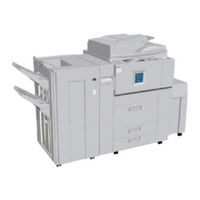
Ricoh B064 SERIES Service Manual (1060 pages)
Ricoh MFP Service manual
Brand:
Ricoh
| Category:
All in One Printer
| Size: 22.64 MB
Table of Contents
B064 Series (B064/B065) B140 Series (B140/B141/B142/B143/B163/B228) G126
13
Service Manual
1
Table of Contents
13
Installation
31
Installation
33
Installation Requirements
35
Operating Environment
35
Machine Level
36
Minimum Space Requirements
37
B064 Series
38
Dimensions
38
B140 Series
39
Power Requirements
40
Main Machine (B064 Series/B140 Series)
41
Accessory Check
41
Installation Procedure
42
Removing Tapes and Retainers
42
Connecting the ADF
44
Removing and Filling the Development Unit
45
Re-Installing the Development Unit
47
Initializing the Drum Settings (B064 Series)
48
Initializing the Drum Settings (B140 Series)
49
Tandem Tray
50
Date/Time Setting
52
Machine Level
52
SP Codes
52
A3/Dlt Feeder Kit (B475)
53
Accessory Check
53
Installation Procedure
54
Lct (B473)
56
Accessory Check
56
Installation Procedure
57
Removing Tape
57
Installing the LCT
58
Preparing the Main Machine
58
Lg/B4 Feeder Kit (B474)
60
Accessory Check
60
Installation Procedure
61
3000-Sheet Finishers (B468/B469/B674)
64
Accessory Check
64
Installation Procedure
65
Installation
67
Enabling Booklet Binding
70
Selecting the Staple Supply Name
70
Punch Unit (B377)
71
Accessory Check
71
Installation Procedure
72
Preventive Maintenance
167
Replacement and Adjustment
178
Accessory Check
74
Cover Interposer Tray (B470)
74
Cover Interposer Tray (B470)
75
Installation Procedure
75
Removing Tapes and Retainers
75
Attaching the Extensions
76
Attaching the Interposer Tray
77
Attaching the Corner Plates for the B478/B706
78
Right Rear Corner Plate (B478/B706 Only)
78
Right Front Corner Plate (B478/B706 Only)
79
Attaching the Finisher to the Machine
80
9-Bin Mailbox (B471)
82
Accessory Check
82
Installation
83
Installation Procedure
83
Removing Tapes and Retainers
83
Key Counter Bracket (B452)
85
Copy Connector Kit
86
Copy Connector Kit (B525-10, -12) for B064 Series
86
Installation
88
Installing the Hardware
89
Accessory Check
93
Copy Connector Kit (B328-03) for B140 Series
93
Preparation
94
Installation
95
Accessory Check
98
Sheet Finisher (B478/B706)
98
Installation
99
When You Move the Finisher to a New Location
102
Accessory Check
103
Punch Unit (B531/A812)
103
Accessory Check
108
Installation
108
Jogger Unit (B513)
108
Installation
109
Accessory Check
110
Z-Folding Unit B660
110
Before You Begin
111
Installation Procedure
111
Unpacking
111
Docking to the Finisher
112
Docking to the Main Frame
115
Accessory Check
117
Mfp Options: B064 Series
117
Printer/Scanner Kit (G338), Printer Kit (G339)
117
Inserting Dimms
118
Installation Procedure
118
Installation Procedure
119
Ps3 (B525-08)
121
Accessory Check
122
Installation Procedure
122
Usb 2.0 (B525-01)
122
USB SP Settings
123
Accessory Check
124
Ieee1394 (G561) Firewire Interface
124
Installation Procedure
125
UP Mode Settings for IEEE 1394
126
SP Mode Settings for IEEE 1394
127
Accessory Check
128
Ieee802.11B Wireless Lan (G628)
128
Installation Procedure
129
UP Mode Settings for Wireless LAN
130
SP Mode Settings for 802.11B Wireless LAN
132
File Format Converter (Mlb) (B519)
133
Accessory Check
134
Installation Procedure
134
Installing the Firmware
134
Installing the Hardware
135
Mfp Options: B140 Series
136
Overview
136
Accessory Check
137
Printer/Scanner Kit (B659)
137
Installation
138
Accessory Check
141
Installation
141
Ps3 (B525-15)
141
Accessory Check
142
Installation
142
Usb 2.0 Interface Board (B596-01)
142
Accessory Check
143
Ieee 1394 Interface Board (B581-01)
143
Installation
143
Accessory Check
144
Ieee 802.11B Interface Board (B582-01, -02)
144
Installation
144
Accessory Check
146
Bluetooth Interface Unit (G377)
146
Installation
146
Accessory Check
147
File Format Converter (B609)
147
Installation
147
Accessory Check
148
Data Overwrite Security Unit (B735)
148
Seal Check and Removal
148
Dimensions
151
Main Machine (G126)
151
Removing and Filling the Development Unit
154
Re-Installing the Development Unit
156
Initializing the Drum Settings
157
Tandem Tray
158
Leveling Stopper
160
Machine Leveling
160
Call Light Setting
161
Main Machine
167
Pm Tables
167
Preventive Maintenance
167
Cover Interposer Tray B470
171
LCT (Large Capacity Tray) B473
171
Optional Peripheral Devices
171
Related Sp Codes
172
Sheet Finisher B478/B706
172
Sheet Finisher with 50-Sheet Stapler and Saddle-Stitching B468/B469/B674
172
Z-Folding Unit Type 2105 (B660)
172
Drum Unit
175
General Cautions
175
Replacement and Adjustment
175
Scanner Unit
176
Transfer Belt Unit
176
Charge Corona
177
Development
177
Cleaning
178
Fusing Unit
178
Paper Feed
178
Used Toner
178
Lubricants
179
Special Tools
179
Special Tools and Lubricants
179
Front Door
180
Operation Panel
180
Operation Panel and External Covers
180
Right Covers
181
Left Covers
182
Rear Covers
183
Adf
184
Adf and Top Covers
184
Scanner
184
Top Covers
185
Exposure Glass
186
Scanner Original Size Sensors
187
Lens Block
188
Exposure Lamp
189
Lamp Regulator
190
Scanner Motor Drive Board (Sdrb)
191
Scanner Motor
192
Scanner Hp Sensor
193
Preparation for Removal
194
Scanner Wire Replacement
194
Wire Removal: Back
195
Wire Removal: Front
196
Attaching the New Wire
197
Scanner Heater
199
Caution Decals
200
Laser Unit
200
Ld Unit and Polygon Motor
201
Laser Synchronization Detector Replacement
203
Laser Unit Alignment
204
Development Unit Removal
206
Drum Unit
206
Removal
206
Re-Installation
207
Replacement with a Used Development Unit
207
Charge Corona Unit
208
Charge Corona Wire and Grid
209
Charge Corona Wire Cleaning Pads
210
Opc Drum Removal
211
Dusting the Drum Surface
212
Ptl (B140 Series Only)
213
Drum Potential Sensor
214
Quenching Lamp
214
Cleaning Blade
215
Cleaning Filter
215
Cleaning Brush
216
ID Sensor
217
Pick-Off Pawls
217
SM B064Series/B140 Series/G126
217
Drum Motor
218
Toner Collection Bottle
219
Toner Separation Unit
219
Internal Dust Filter
220
Optics Dust Filter
220
Ozone Filters
220
Developer Replacement
221
Development Unit
221
Development Filter
223
Entrance Seal and Side Seals
224
Td Sensor
225
Toner End Sensor
225
Toner Supply Motor
226
Development Motor
227
Transfer Belt Unit
228
Transfer Belt
229
Transfer Roller Cleaning Blade
231
Discharge Plate
232
Transfer Power Pack
233
Fusing Unit
234
Fusing Pressure Release Motor (B140 Series)
235
Fusing Pressure Release Hp Sensor (B140 Series)
236
B064 Series
237
Fusing Unit Thermistors and Thermostats
237
B140 Series
238
Web Cleaning Roller
239
Web Unit Disassembly
239
Web Unit Assembly
240
Web Motor and Web End Sensor
241
B064 Series
242
Pressure Roller Cleaning Unit
242
B140 Series
243
B064 Series: Fusing Lamps
244
Fusing Lamps, Hot Roller, and Pressure Roller
244
B140 Series: Fusing Lamps
245
Important Notes about Fusing Unit Assembly (B064 Series)
250
Pressure Roller
251
B064 Series
252
Stripper Pawls
252
B140 Series
253
Nip Band Width Adjustment
254
Fusing Unit Exit Sensor
255
Fusing/Exit Motor
256
Fusing Exit and Exit Unit Entrance Sensors
257
Duplex Unit
258
Duplex Unit Removal
258
Duplex Unit Side-To-Side Adjustment
259
Jogger Fence Adjustment
259
Duplex Inverter Motor
260
Duplex Motors
260
Duplex Jogger and Transport Motors
261
Duplex Transport Clutch/Jogger Hp Sensor
262
Duplex Entrance Sensor
263
Duplex Transport Sensor 3
264
Inverter Exit Sensor, Transport Sensors 1 & 2
265
Duplex Jogger Belt Adjustment
266
Paper Feed
267
Paper Tray Removal
267
Rear Fence Return Sensor Replacement
269
Rear Fence Hp Sensor Replacement
270
Tandem Right Tray Paper Sensor Replacement
271
Bottom Plate Lift Wire Replacement
272
Tandem Tray Paper Size Change
274
Pick-Up, Feed, Separation Roller Replacement
277
Feed Unit
278
Separation Roller Pressure Adjustment
280
Relay Sensor
281
By-Pass Paper Size Detection Board
282
By-Pass Tray Rollers
283
By-Pass Separation Roller Pressure Adjustment
284
Registration Sensor
285
Registration and By-Pass Unit Removal
286
Bcu Board (Base Engine Control Unit)
288
Pcbs and Hdd
288
B064 Series: Controller Board
289
Controller Board
289
B064 Series: IPU Board
291
Ipu Board
291
Development Power Pack
295
B064 Series
296
Psu, Pfc Boards
296
B064 Series HDD
297
Hdd
297
Nvram
299
Dimms
301
Adf (B140 Series/B064 Series)
302
Adf Covers
302
Feed Unit
303
Feed Belt and Pick-Up Roller
304
Separation Roller
305
Registration Sensor
306
Adf Control Board
307
Original Width, Interval, and Skew Correction Sensors
308
Original Length Sensors
309
Df Position and Aps Sensor
310
Other Adf Sensors
311
Bottom Plate Lift Motor
312
Feed Motor
312
Exit Motor and Transport Motor
313
Pick-Up Roller Motor and Hp Sensor
314
Cis Power Supply Board and Cis Unit
315
Adf Exit Sensor
316
Copy Image Adjustments: Printing/Scanning
317
Printing
317
Registration - Leading Edge/Side-To-Side
317
Blank Margin
318
Registration Buckle Adjustment
318
Magnification
319
Registration: Platen Mode
319
Scanning (B140 Series/B064 Series)
319
Adf Scanning Adjustments (B140 Series/B064 Series)
320
ADF Skew Correction
320
DIP Switch Settings (ADF Main Board)
320
Vertical Black Lines
320
Touch Screen Calibration (B140 Series/B064 Series)
322
Troubleshooting
323
Overview
325
Important Sp Codes
326
Recovery Methods
326
Download Error Codes
327
Jam Detection
330
Sensor Locations
330
Feed, Transport, Feed Out: Face-Up
331
Timing Charts
331
Transport, Inverter, Feed Out: Face-Down
332
Duplex Transport
333
Program Download
334
B064 Series Service Call Conditions
335
B064 Series Service Mode
335
B064 Series Sc Code Descriptions
336
SC100: Scanning System
336
SC300: Image Development System (1)
339
SC400: Image Development System (2)
344
SC500: Feed, Transport, Duplexing, and Fusing Systems
345
SC600: Data Communication
348
SC700: Peripherals
350
SC800: Overall System
353
SC900: Miscellaneous
356
Additional Sc Codes Printed in Smc Report (B064 Series)
358
B140 Series and G126 Service Mode
360
Service Mode Lock/Unlock
360
B140 Series and G126 Service Call Conditions
361
B140 Series and G126 Sc Code Descriptions
362
SC100: Scanning System
362
SC300: Image Development System (1)
365
SC400: Image Development System (2)
370
SC500: Feed, Transport, Duplexing, and Fusing Systems
371
SC600: Data Communication
375
SC700 Series: Peripherals
377
SC800: Overall System
381
SC900: Miscellaneous
386
Jam Codes (B140 Series and G126)
390
Main Unit: Paper Jam Errors
390
Finisher B468/B674 Jam Codes
391
Finisher B469 Jam Codes
391
Cover Interposer Tray B470 Jam Codes
392
Finisher B478/B706 Jam Codes
392
Mailbox B471 Jam Codes
392
Z-Folding Unit B660 Jam Codes
393
Additional Sc Codes Printed in Smc Report
394
Series and G126)
394
Blown Fuse Conditions
397
Common Problems
397
Other Problems (All Models)
397
Frequent Paper Jams
398
Detailed Descriptions
601
Specifications
741
Service Tables
401
Entering and Exiting SP Mode
403
Service Program Mode
403
Service Program Mode Operation
403
Series)
404
To Switch to the Copy Window for Test Printing
404
Using the SP Mode
404
Service Mode Lock/Unlock (B140 Series Only)
405
SP Mode Button Summary
406
SP Mode Print (SMC Print)
407
Memory All Clear: Sp5801
408
Resets
408
SM IX B064Series/B140 Series/G126
409
Resetting Copy/Document Server Features Only
410
Resetting Scanner Features Only
410
Resetting the System
410
Software and Setting Reset
410
Software Reset
410
Printing Test Pattern: Sp2902-003
411
Test Pattern Printing
411
Test Pattern Table
412
Ipu Front/Back Test Patterns: Sp2902-001,002
413
Test Pattern Table
414
Ipu Printing Test Pattern: Sp2902-004
415
Software Update
416
Software Update Procedure: B140 Series
416
Error Message Table
420
Downloading Stamp Data
421
Updating the LCDC for the Operation Panel
421
NVRAM Data Upload/Download
422
Software Update Procedure: B064 Series
423
GW Controller/Bcu Update
424
Forced Update
425
Stamp Data Update
425
Operation Panel Software Update
426
Netfile Firmware Update
427
NIB Update
427
Scanner Update
427
Firmware Update Notes
428
NVRAM Update
428
Overview
429
Sd Card Application Move
429
Move Exec
430
Undo Exec
430
Service Program Mode Tables
431
Service Table Key
431
Copier Service Table
432
Sp1Xxx Feed
432
Sp2Xxx Drum
437
Sp3Xxx Processing
455
Sp4Xxx Scanner
458
Sp5Xxx Mode
468
Sp6Xxx Peripherals
502
Sp7Xxx Data Logs
508
Sp8Xxx: Data Log2
522
Printer Service Table
551
Scanner Service Table
552
Copier Input Check: Sp5803
564
Input/Output Check
564
Copier Output Check: Sp5804
570
Adf Input Check: Sp6007
572
Adf Output Check: Sp6008
573
Finisher Input Check: Sp6117 (B478/B704 Only)
574
Finisher Output Check: Sp6118
576
Switching on and Setting up Save Debug Log
577
Using the Debug Log
577
Retrieving the Debug Log from the Hdd
580
Recording Errors Manually
581
New Debug Log Codes
582
SP5857-015 Copy SD Card-To-SD Card: any Desired Key
582
SP5857-016 Create a File on HDD to Store a Log
582
SP5857-017 Create a File on SD Card to Store a Log
582
Overview
583
User Tools
583
B064 Series System Settings
584
System Settings
584
B140 Series System Settings
586
Copier/Document Server Features
589
Counter
593
Inquiry
593
Dip Switches
594
Controller Board
595
Detailed Descriptions
599
Overview
599
Paper Path (with Cover Interposer Tray)
601
Paper Path (with 9-Bin Mailbox)
602
Block Diagram
604
Board Structure
604
BCU (Base Engine Control Unit)
605
Component Descriptions
605
Controller Board
605
MB (Mother Board)
605
CNB (Connection Board)
606
PFC (Paper Feed Control)
606
SBU (Sensor Board Unit)
606
SDRB (Scanner Driver Board)
606
VIB (Video Interface Board)
606
HDD (Hard Disk Drive)
607
Copy Process Overview
608
Adf (B140 Series/B064 Series)
610
Overview
610
Adf Drive Layout
611
Pick-Up Roller Lift
612
Bottom Plate Lift
613
Original Separation
614
Original Transport
615
Original Skew Correction
616
Original Size Detection
618
Adf Scanning
621
Jam Detection
622
Overview
623
Scanning (B140 Series/B064 Series)
623
Scanner Drive
624
Original Size Detection
625
Sensors
625
Detection Timing
626
Book Mode
627
Scanning Magnification
627
Auto Image Density (Ads)
628
Xenon Lamp → CCD ADS
628
Image Processing
629
Overview
629
Image Processing Flow
630
Image Processing Modes
631
Custom Settings for each Mode: Image Quality
632
Image Quality Sp Adjustments
632
Custom Settings for each Mode: Line Width Correction
634
Custom Setting: Duplex Scanning Mode Original Image Quality Settings
636
Settings Adjustable for each Original Mode
637
Relation between the Sp and up Settings
638
Image Processing Troubleshooting
640
Improving the Appearance of a Copy of a Color Document
640
Removing Background from Coarse Paper
640
Removing Vertical White Lines During Duplex Scanning
641
Equalizing Duplex Scanned Image Quality of Front/Back Sides
642
Equalizing Image Quality of Front Sides for Duplex and Simplex Modes
642
Laser Exposure
643
Overview
643
Optical Path
644
Four-Beam Exposure
645
Cooling Fan
646
Ld Safety Switches
647
Drum Unit
648
Overview
648
Drum Drive
649
Opc Drum
649
Drum Charge
650
Charge Corona Wire Cleaning
651
Drum Pick-Off Mechanism
652
Drum Cleaning
653
Drum Ventilation and Ozone Filter
654
Toner Recycling
655
Error Detection
656
Mechanism
656
Waste Toner Collection
656
Process Control
657
What Happens at Power on
657
Drum Potential Sensor Calibration
658
Development Bias, Bias Grid, and LD Adjustment
659
ID Sensor Calibration (Vsg)
661
TD Sensor Calibration (Vref)
661
Development and Toner Supply
662
Development Unit
662
Overview
662
Toner Supply
663
Development Unit
664
Developer/Toner Mixing (Agitation)
665
Development Bias
666
Toner Supply
667
Development Unit Drive and Ventilation
668
Shutter Mechanism
669
Toner End Sensor
669
Toner Bottle Supply and Ventilation
670
Sensor Control Mode
671
Toner Supply Control
671
Pixel Count Toner Supply Mode
672
Determining Vref
673
TD Sensor Initialization
673
Abnormal ID Sensor Output
674
Abnormal TD Sensor Output
674
Toner Supply Without ID Sensor and TD Sensors
674
Toner End Detection
675
Toner End Recovery
675
Image Transfer and Paper Separation
676
Overview
676
Mechanism
677
Transfer Belt Lift
677
Timing
678
Transfer Belt Charge
679
Transfer Current Settings
680
Transfer Current Circuit
681
Transfer Belt Drive and Paper Transport
682
Transfer Belt Cleaning
683
Anti-Condensation Heater
684
Overview
685
Paper Feed
685
Built-In Feed Stations
686
By-Pass Feed
686
Jam Removal
686
Paper Registration
686
Tray Capacities
686
Drive
687
Bottom Plate Lift
688
Tray and Paper Lift Mechanism – Tray 2,3
688
Lift Sensor
689
Paper Feed and Separation Mechanism
690
Paper Feed and Separation: no Paper Present
690
Paper Feed and Separation
691
Separation Roller Release Mechanism
692
Paper Near-End and Paper End – Trays 2 and 3
693
Paper Size Detection
694
Tandem Tray (Tray 1)
694
Universal Cassettes (Tray 2, 3)
694
Anti-Condensation Heaters
695
Overview
696
Tandem Tray – Tray 1
696
Connecting the Left and Right Sides of the Tray
697
Paper Lift/Remaining Paper Detection
698
Fence Drive
700
Rear Fence Drive
701
Tray Side-To-Side Positioning
702
Tray Positioning Mechanism – Trays 1 to 3
703
By-Pass Feed and Separation
704
By-Pass Tray
704
By-Pass Tray Paper End Detection
705
By-Pass Paper Size Detection
706
Overview
707
Paper Registration
707
Paper Registration Drive
708
Jam Removal at Paper Registration
709
B064 Series and G126
710
Image Fusing and Paper Exit
710
Overview
710
B140 Series
711
B064 Series and G126
712
Fusing Mechanism
712
B140 Series
713
B064 Series and G126
714
Pressure Roller
714
B140 Series
715
Hot Roller Cleaning
716
Overview
716
Web Drive
717
Web Near-End
717
Fusing Unit Entrance Guide
718
Fusing Unit Drive
719
Cpm down Mode
720
Fusing Temperature Control
721
Exit
723
Exit Junction Gate
724
Duplex Unit
725
Overview
725
Duplex Drive
726
Inverter Feed-In and Jogging
727
Inverter Operation
727
Inverter Feed-Out
728
Duplex Tray Feed
729
Duplex Interleave Feed
730
Energy Saver Modes
732
Overview
732
Energy Saver Mode
733
Entering the Energy Saver Mode
733
Return to Stand-By Mode
733
What Happens in Energy Saver Mode
733
Entering the Low Power Mode
734
Low Power Mode
734
Return to Stand-By Mode
734
What Happens in Low Power Mode
734
Auto off Mode
735
Disabling Auto off Mode
735
Entering Auto off Mode
735
Returning to Stand-By Mode
735
What Happens in Auto off Mode
735
Entering Night Stand-By and Night Modes
736
Night Mode
736
Returning to Stand-By Mode
736
What Happens in Night Stand-By and Night Modes
736
Copier (B140 Series/B064 Series) Printer (G126)
739
General Specifications
739
Adf (B140 Series/B064 Series)
740
Power Consumption
741
Machine Configuration
743
A3/Dlt Kit (B475)
744
Lct (Large Capacity Tray) (B473)
744
Optional Equipment
744
General
745
Lower Tray
745
Proof Tray
745
Sheet Finisher with Saddle-Stitch and 50-Sheet Stapler (B468)
745
Upper Tray
745
Saddle-Stitch Staple Specifications
746
Staple Specifications
746
General
747
Lower Tray
747
Proof Tray
747
Sheet Finisher with 50-Sheet Stapler (B469)
747
Staple Specifications
747
General
748
Sheet Finisher with Saddle-Stitch and 50-Sheet Stapler (B674)
748
Lower Tray
749
Proof Tray
749
Saddle-Stitch Staple Specifications
750
Punch Unit (B377)
751
Cover Interposer Tray (B470)
752
Sheet Finisher (B478/B706)
753
Bin Mailbox (B471)
756
Jogger Unit (B513)
756
Lg/B4 Kit (B474)
756
Z-Folding Unit (B660)
756
Ricoh B064 SERIES Service Manual (927 pages)
Brand:
Ricoh
| Category:
All in One Printer
| Size: 34.88 MB
Table of Contents
Table of Contents
13
Installation
35
Machine Level
36
Minimum Space Requirements
37
Power Requirements
38
Option Correlation Chart
39
Printer Option Correlation
40
Main Machine (B064/B065)
41
Installation Procedure
42
Connecting the ADF
44
Removing and Filling the Development Unit
45
Re-Installing the Development Unit
47
Initializing the Drum Settings
48
Tandem Tray
49
Machine Level
51
A3/Dlt Feeder Kit (B475)
52
Installation Procedure
53
Lct (B473)
55
Installation Procedure
56
Preparing the Main Machine
57
Lg/B4 Feeder Kit (B474)
59
Installation Procedure
60
Sheet Finishers (B468/B469)
63
Installation Procedure
64
B468/B469 Installation
65
Selecting the Staple Supply Name
67
Punch Unit (B377)
68
Installation Procedure
69
Cover Interposer Tray (B470)
71
Installation Procedure
72
Bin Mailbox (B471)
75
Installation Procedure
76
Printer/Scanner Kit (G338), Printer Kit (G339)
78
Installation Procedure
79
Installation Procedure
80
Ps3 (B525-08)
82
Usb 2.0 (B525-01)
83
Installation Procedure
84
Usb Sp Settings
85
Accessory Check
86
Installation Procedure
87
Up Mode Settings for Ieee 1394
88
Sp Mode Settings for Ieee 1394
89
B Wireless Lan (G628)
90
Installation Procedure
91
Up Mode Settings for Wireless Lan
92
Sp Mode Settings for 802.11B Wireless Lan
94
Key Counter
95
Preventive Maintenance
99
Optional Peripheral Devices
103
Replacement and Adjustment
107
Transfer Belt Unit
108
Charge Corona
109
Cleaning
110
Special Tools and Lubricants
111
Operation Panel and External Covers
112
Right Covers
113
Left Covers
114
Rear Covers
115
Scanner
116
Top Covers
117
Exposure Glass
118
Scanner Original Size Sensors
119
Lens Block
120
Exposure Lamp
121
Lamp Regulator
122
Scanner Motor Drive Board (Sdrb)
123
Scanner Motor
124
Scanner Hp Sensor
125
Scanner Wire Replacement
126
Wire Removal: Back
127
Wire Removal: Front
128
Attaching the New Wire
129
Scanner Heater
131
Laser Unit
132
Ld Unit and Polygon Motor
133
Laser Synchronization Detector Replacement
135
Laser Unit Alignment
136
Drum Unit
138
Re-Installation
139
Charge Corona Unit
140
Charge Corona Wire and Grid
141
Charge Corona Wire Cleaning Pads
142
Opc Drum Removal
143
Quenching Lamp
144
Cleaning Filter
145
Cleaning Brush
146
Pick-Off Pawls
147
Drum Motor
148
Toner Collection Bottle
149
Ozone Filters
150
Development Unit
151
Development Filter
153
Entrance Seal and Side Seals
154
Td Sensor
155
Toner Supply Motor
156
Development Motor
157
Transfer Belt Unit
158
Transfer Belt
159
Transfer Roller Cleaning Blade
161
Discharge Plate
162
Transfer Power Pack
163
Fusing Unit
164
Fusing Unit Thermistors and Thermostats
165
Web Cleaning Roller
166
Web Unit Assembly
167
Web Motor and Web End Sensor
168
Pressure Roller Cleaning Unit
169
Fusing Lamps, Hot Roller, and Pressure Roller
170
Important Notes about Fusing Unit Assembly
173
Pressure Roller
174
Stripper Pawls
175
Nip Band Width Adjustment
176
Fusing Unit Exit Sensor
177
Fusing/Exit Motor
178
Fusing Exit and Exit Unit Entrance Sensors
179
Duplex Unit
180
Duplex Unit Side-To-Side Adjustment
181
Duplex Motors
182
Duplex Jogger and Transport Motors
183
Duplex Transport Clutch/Jogger Hp Sensor
184
Duplex Entrance Sensor
185
Duplex Transport Sensor 3
186
Inverter Exit Sensor, Transport Sensors 1 & 2
187
Duplex Jogger Belt Adjustment
188
Paper Feed
189
Rear Fence Return Sensor Replacement
191
Rear Fence Hp Sensor Replacement
192
Tandem Right Tray Paper Sensor Replacement
193
Tandem Lct Paper Size Change
196
Pick-Up, Feed, Separation Roller Replacement
199
Feed Unit
200
Separation Roller Pressure Adjustment
202
Relay Sensor
203
By-Pass Paper Size Detection Board
204
By-Pass Tray Rollers
205
By-Pass Separation Roller Pressure Adjustment
206
Registration Sensor
207
Registration and By-Pass Unit Removal
208
Pcbs and Hdd
210
Controller Board
211
Ipu Board (Image Processing Unit)
212
Psu, Pfc Boards
213
Nvram
214
Adf Covers
215
Feed Unit
216
Feed Belt and Pick-Up Roller
217
Separation Roller
218
Registration Sensor
219
Adf Control Board
220
Original Width, Interval, and Skew Correction Sensors
221
Original Length Sensors
222
Df Position and Aps Sensor
223
Other Adf Sensors
224
Feed Motor
226
Exit Motor and Transport Motor
227
Pick-Up Roller Motor and Hp Sensor
228
Cis Power Supply Board and Cis Unit
229
Adf Exit Sensor
231
Copy Image Adjustments: Printing/Scanning
232
Blank Margin
233
Registration: Platen Mode
234
Adf Scanning Adjustments
235
ADF Skew Correction
236
Touch Screen Calibration
237
Troubleshooting
241
Recovery Methods
242
Download Error Codes
243
Controller Board Self-Diagnostic Test
245
Jam Detection
246
Timing Charts
247
Transport, Inverter, Feed Out: Face-Down
248
Duplex Transport
249
Service Call Conditions
250
Sc Code Descriptions
251
Image Development System (1)
254
Image Development System (2)
259
Feed, Transport, Duplexing, and Fusing Systems
260
Data Communication
263
Peripherals
265
Overall System
268
Miscellaneous
271
Additional Sc Codes Printed in Smc Report
273
Blown Fuse Conditions
277
Service Tables
281
Using the SP Mode
282
SP Mode Button Summary
283
Resets
284
Software Reset
285
Test Pattern Printing
286
Test Pattern Table
287
Printing Test Pattern: Sp2902 003
288
Ipu Printing Test Pattern: Sp2902 004
289
Software Update
290
Software Update Procedure
291
Forced Update
292
Operation Panel Software Update
293
Scanner Update
294
User Tools
296
System Settings
297
Copier/Document Server Features
298
Printer
300
Scanner
301
Service Program Mode Tables
302
SP2-XXX Drum
306
Sp3Xxx Processing
323
SP4-XXX Scanner
325
SP5-XXX Mode
335
SP6-XXX Peripherals
351
SP7-XXX Data Logs
354
SP8-XXX Design Factory Use
363
SP9-XXX Design Factory Use
364
Printer Service Table
367
Scanner Service Table
368
Input/Output Check
375
Detailed Descriptions
387
Overview
389
Adf Drive Layout
390
Pick-Up Roller Lift
391
Bottom Plate Lift
392
Original Separation
393
Original Transport
394
Original Skew Correction
395
Original Size Detection
397
Adf Scanning
400
Jam Detection
401
Scanning
402
Scanner Drive
403
Original Size Detection
404
Detection Timing
405
Scanning Magnification
406
Auto Image Density (Ads)
407
Image Processing
408
Image Processing Flow
409
Image Processing Modes
410
Image Quality Sp Adjustments
411
Relation between the Sp and up Settings
417
Image Processing Troubleshooting
419
Laser Exposure
422
Optical Path
423
Four-Beam Exposure
424
Cooling Fan
425
Ld Safety Switches
426
Drum Unit
427
Opc Drum
428
Charge Corona Wire Cleaning
429
Drum Pick-Off Mechanism
430
Drum Cleaning
431
Drum Ventilation and Ozone Filter
432
Toner Recycling
433
Waste Toner Collection
434
Process Control
435
Drum Potential Sensor Calibration
436
Development Bias, Bias Grid, and LD Adjustment
437
ID Sensor Calibration (Vsg)
439
Development and Toner Supply
440
Toner Supply
441
Development Unit
442
Developer/Toner Mixing (Agitation)
443
Development Bias
444
Toner Supply
445
Development Unit Drive and Ventilation
446
Toner End Sensor
447
Toner Bottle Supply and Ventilation
448
Toner Supply Control
449
Pixel Count Toner Supply Mode
450
TD Sensor Initialization
451
Toner Supply Without ID Sensor and TD Sensors
452
Toner End Detection
453
Image Transfer and Paper Separation
454
Transfer Belt Lift
455
Timing
456
Transfer Belt Charge
457
Transfer Current Settings
458
Transfer Current Circuit
459
Transfer Belt Drive and Paper Transport
460
Transfer Belt Cleaning
461
Anti-Condensation Heater
462
Overview
463
Tray Capacities
464
Drive
465
Tray and Paper Lift Mechanism – Tray 2,3
466
Lift Sensor
467
Paper Feed and Separation Mechanism
468
Paper Feed and Separation
469
Separation Roller Release Mechanism
470
Paper Near-End and Paper End – Trays 2 and 3
471
Paper Size Detection
472
Anti-Condensation Heaters
473
Tandem Tray – Tray 1
474
Connecting the Left and Right Sides of the Tray
475
Paper Lift/Remaining Paper Detection
476
Fence Drive
478
Rear Fence Drive
479
Tray Side-To-Side Positioning
480
Tray Positioning Mechanism – Trays 1 to 3
481
By-Pass Tray
482
By-Pass Tray Paper End Detection
483
By-Pass Paper Size Detection
484
Paper Registration
485
Paper Registration Drive
486
Jam Removal at Paper Registration
487
Overview
488
Fusing Mechanism
489
Pressure Roller
490
Hot Roller Cleaning
491
Web Drive
492
Fusing Unit Entrance Guide
493
Fusing Unit Drive
494
Cpm down Mode
495
Exit
497
Exit Junction Gate
498
Duplex Unit
499
Duplex Drive
500
Inverter Operation
501
Inverter Feed-Out
502
Duplex Tray Feed
503
Duplex Interleave Feed
504
Energy Saver Modes
506
Energy Saver Mode
507
Low Power Mode
508
Auto off Mode
509
Night Mode
510
Specifications
513
Power Consumption
515
Machine Configuration
516
Component Layout
517
Paper Path (with Cover Interposer Tray)
519
Paper Path (with 9-Bin Mailbox)
520
Drive Layout
521
Board Structure
522
Component Descriptions
523
SBU (Sensor Board Unit)
524
HDD (Hard Disk Drive)
525
Optional Equipment
526
Lower Tray
527
Sheet Finisher with 50-Sheet Stapler B469
528
Punch Unit for B468/B469
529
Cover Interposer Tray B470 Paper Sizes
530
Main Copier
531
Mailbox
536
Large Capacity Tray
537
Cover Interposer
538
BCU Firmware Modification History
541
GW Firmware Modification History
542
LCDC Firmware Modification History
544
Advertisement
Ricoh B064 SERIES Service Manual (25 pages)
Brand:
Ricoh
| Category:
All in One Printer
| Size: 0.93 MB
Table of Contents
Service Manual
1
Troubleshooting
9
Overview
10
Tandem Tray
11
A3/Dlt Feeder Kit (B475)
13
Punch Unit (B377)
14
Bin Mailbox (B471)
15
Scanner
16
Specifications
17
Program Download
18
Fusing Unit
19
Special Tools
20
Scanner
23
Ricoh B064 SERIES Service Manual (20 pages)
Brand:
Ricoh
| Category:
All in One Printer
| Size: 0.21 MB
Advertisement
Related Products
Ricoh B065
Ricoh B043
Ricoh B022
Ricoh B089
Ricoh B082
Ricoh B045
Ricoh B001
Ricoh B010
Ricoh B031
Ricoh B08
Ricoh Categories
All in One Printer
Printer
Digital Camera
Copier
Printer Accessories
More Ricoh Manuals
Login
Sign In
OR
Sign in with Facebook
Sign in with Google
Upload manual
Upload from disk
Upload from URL