Sign In
Upload
Manuals
Brands
Juniper Manuals
Switch
EX2200-C
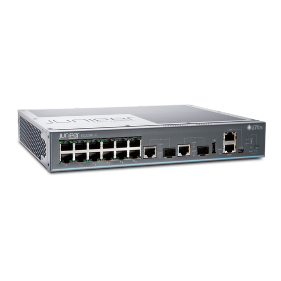
Juniper EX2200-C Compact Ethernet Switch Manuals
Manuals and User Guides for Juniper EX2200-C Compact Ethernet Switch. We have
5
Juniper EX2200-C Compact Ethernet Switch manuals available for free PDF download: Hardware Manual, Quick Start Manual
Juniper EX2200-C Hardware Manual (288 pages)
Brand:
Juniper
| Category:
Switch
| Size: 4.56 MB
Table of Contents
Table of Contents
3
About the Documentation
17
Documentation and Release Notes
17
Supported Platforms
17
Documentation Conventions
17
Table 1: Notice Icons
18
Table 2: Text and Syntax Conventions
18
Documentation Feedback
19
About the Documentation
19
Requesting Technical Support
20
Self-Help Online Tools and Resources
20
Opening a Case with JTAC
20
Overview
23
Chassis Components and Descriptions
23
Chapter 1 System Overview
25
System Overview
25
EX2200 Switches Hardware Overview
25
EX2200 Switches First View
25
Console Port
26
Uplink Ports
26
Cable Guard
27
Power over Ethernet (Poe) Ports
27
Security Slots
27
System Overview
27
Figure 1: Front Panel of an EX2200 Switch with 48 Gigabit Ethernet Ports
28
Figure 2: Front Panel of an EX2200 Switch with 24 Gigabit Ethernet Ports
28
Front Panel of an EX2200 Switch
28
Figure 3: Front Panel of an EX2200-C Switch with 12 Gigabit Ethernet Ports
29
Figure 4: Front Panel of an EX2200-C Switch with 12 Gigabit Ethernet Ports
29
System Overview
29
Figure 5: Rear Panel of an EX2200 Switch with AC Power Supply
30
Rear Panel of an EX2200 Switch
30
EX2200 Switch Models
31
Figure 6: Rear Panel of an EX2200-C-12P Switch with Heatsink
31
Table 3: EX2200 Switch Models
31
EX2200 Switch Hardware and CLI Terminology Mapping
32
Table 4: CLI Equivalents of Terms Used in Documentation for EX2200
32
This Topic Describes
32
Chapter 2 Chassis Components and Descriptions
35
Chassis Physical Specifications for EX2200 Switches
35
Table 5: Physical Specifications of the EX2200 Switch Chassis
35
Chassis Status Leds in EX2200 Switches
36
Figure 7: Chassis Status Leds in an EX2200 Switch Except the EX2200-C
36
Figure 8: Chassis Status Leds in an EX2200-C Switch
36
Table 6: Chassis Status Leds in an EX2200 Switch
36
Management Port Leds in EX2200 Switches
37
Figure 9: Leds on the Management Port on an EX2200 Switch Except the
37
Figure 10: Leds on the Management Port on an EX2200-C Switch
37
Chassis Components and Descriptions
37
Table 7: Link/Activity LED on the Management Port on EX2200 Switches
37
Network Port and Uplink Port Leds in EX2200 Switches
38
Figure 11: Leds on the Network Port
38
Figure 12: Leds on the Uplink Ports and Port Status Mode Leds in an EX2200 Switch Except the EX2200-C Switch Model
38
Table 8: Status LED on the Management Port on EX2200 Switches
38
Figure 13: Port Status Mode Leds of the Dual-Purpose Uplink Ports of an
39
Table 9: Link/Activity LED on the Network Ports and Uplink Ports in EX2200
39
Table 10: Status LED on the Network Ports, Uplink Ports, and Dual-Purpose
39
Chapter 3 Cooling System and Airflow
41
Cooling System and Airflow in an EX2200 Switch
41
Airflow Direction in Non-Poe Models of EX2200 Switches, Except for the EX2200-C Models
41
Airflow Direction in Poe Models of EX2200 Switches, Except for the EX2200-C Models
42
Figure 14: Airflow through Non-Poe Models of EX2200 Switches Except the
42
Figure 15: Airflow through Poe Models of EX2200 Switches Except the EX2200-C Switch Models
43
Chapter 4 Power Supplies
45
Power Supplies
45
Power Supply in EX2200 Switches
45
Table 11: Power Consumed by EX2200 Switches
45
Chapter 5 Viewing System Information
47
Dashboard for EX Series Switches
47
Graphical Chassis Viewer
48
Table 12: Details of a Virtual Chassis Member Switch
48
Table 13: Status of a Member Switch in a Virtual Chassis
48
Note
48
System Information Panel
49
Table 14: System Information
49
Health Status Panel
51
Table 15: Health Status
51
Capacity Utilization Panel
53
Alarms Panel
53
Table 16: Capacity Utilization
53
File System Usage
54
Chassis Viewer
54
Table 17: Chassis Viewer for EX2200 Switches
54
Table 18: Chassis Viewer for EX2200-C and EX2300-C Switches
55
Table 19: Chassis Viewer for EX2300 Switches
56
Table 20: Chassis Viewer for EX3200, EX3300, and EX4200 Switches
57
Table 21: Chassis Viewer for EX3400 and EX4300 Switches
58
Table 22: Chassis Viewer for EX4500 Switches
60
Table 23: Chassis Viewer for EX4550 Switches
61
Table 24: Chassis Viewer for EX6210 Switches
62
Table 25: Chassis Viewer for EX8208 Switches
62
Table 26: Chassis Viewer for EX8216 Switches
64
Table 27: Chassis Viewer for XRE200 External Routing Engines
64
Part 2 Site Planning, Preparation, and Specifications
67
Chapter 6 Preparation Overview
69
Environmental Requirements and Specifications for EX Series Switches
71
Table 29: EX Series Switch Environmental Tolerances
71
General Site Guidelines
75
Site Electrical Wiring Guidelines
76
Table 30: Site Electrical Wiring Guidelines
76
Chassis Physical Specifications for EX2200 Switches
77
Requirements for Mounting an EX2200 Switch on a Desktop or Wall
77
Table 31: Physical Specifications of the EX2200 Switch Chassis
77
Rack Requirements for EX2200 Switches
78
Table 32: Rack Requirements and Specifications for the Switch
78
Cabinet Requirements for EX2200 Switches
79
Table 33: Cabinet Requirements and Specifications for the Switch
79
Clearance Requirements for Airflow and Hardware Maintenance for EX2200 Switches
80
Figure 16: Clearance Requirements for Airflow and Hardware Maintenance for EX2200 Switches Except EX2200-C Switch Models
81
Figure 17: Clearance Requirements for Airflow and Hardware Maintenance for
81
Figure 18: Airflow through Poe Models of EX2200 Switches Except EX2200-C
82
Figure 19: Airflow through Non-Poe Models of EX2200 Switches Except EX2200-C Switch Models
82
Preparation Overview
69
Site Preparation Checklist for EX2200 Switches
69
Table 28: Site Preparation Checklist
69
Chapter 7 Power Specifications and Requirements
85
Power Specifications for EX2200 Switches
85
Poe)
85
Table 34: AC Power Supply Electrical Specifications for EX2200 Switches
85
Table 35: DC Power Supply Electrical Specifications for EX2200 Switches
85
Switches
85
AC Power Cord Specifications for EX2200 Switches
86
Figure 20: AC Plug Types
87
Table 36: AC Power Cord Specifications
87
Calculating the EX Series Switch Fiber-Optic Cable Power Budget
88
Calculating the EX Series Switch Fiber-Optic Cable Power Margin
88
Table 37: Estimated Values for Factors Causing Link Loss
89
Chapter 8 Transceiver and Cable Specifications
91
Pluggable Transceivers Supported on EX2200 Switches
91
Table 38: Optical Interface Support and Copper Interface Support for Gigabit Ethernet SFP Transceivers in EX2200 Switches Except EX2200-C
93
Table 39: Optical Interface Support for Fast Ethernet SFP Transceivers in EX2200 Switches Except EX2200-C Switches
112
Table 40: Optical Interface Support and Copper Interface Support for SFP Transceivers in EX2200-C Switches
118
Pluggable Transceivers Supported on EX Series Switches
123
Network Cable Specifications for EX2200 Switches
125
And Dispersion
125
Signal Loss in Multimode and Single-Mode Fiber-Optic Cable
125
Attenuation and Dispersion in Fiber-Optic Cable
126
Chapter 9 Pinout Specifications
127
Mini-USB Port Specifications for an EX2200 Switch
128
USB Port Specifications for an EX Series Switch
129
Table 42: Mini-USB Type-B Console Port Pinout Information for EX2200-C
129
Management Port Connector Pinout Information for an EX2200 Switch
130
Table 43: Management Port Connector Pinout Information for EX2200
130
Network Port Connector Pinout Information for an EX2200 Switch
131
RJ-45 to DB-9 Serial Port Adapter Pinout Information for a Switch
131
Table 44: Network Port Connector Pinout Information for EX2200 Switches
131
Table 45: RJ-45 to DB-9 Serial Port Adapter Pinout Information
132
Pinout Specifications
127
Console Port Connector Pinout Information for an EX Series Switch
127
Table 41: EX Series Switches Console Port Connector Pinout Information
127
Initial Installation and Configuration
133
Chapter 10 Unpacking the Switch
135
Parts Inventory (Packing List) for an EX2200 Switch
136
Table 46: Parts List for EX2200 Switches
136
Registering Products-Mandatory for Validating Slas
137
Unpacking the Switch
135
Unpacking an EX2200 Switch
135
Chapter 11 Installing the Switch
139
Installing and Connecting an EX2200 Switch
139
Mounting an EX2200 Switch
140
Table 47: EX2200 Switch Mounting Methods
140
Mounting an EX2200 Switch on a Desk or Other Level Surface
141
Figure 21: Attaching Rubber Feet to a Switch Chassis
142
Figure 22: Attaching a Cable Guard to an EX2200-C Switch
143
Figure 23: Securing the EX2200-C Switch Using Security Slots
143
Mounting an EX2200 Switch on Two Posts of a Rack or Cabinet
144
Figure 24: Attaching the Mounting Bracket Along the Front of the Switch
145
Mounting an EX2200 Switch on Four Posts of a Rack or Cabinet
146
Figure 25: Mounting the Switch on Two Posts of a Rack
146
Figure 26: Attaching the Front-Mounting Bracket to the Side Mounting-Rail
148
Figure 27: Attaching the Side Mounting-Rail to the Switch Chassis
148
Figure 28: Mounting the Switch to the Front Posts of a Rack
149
Figure 29: Sliding the Rear Mounting-Blades into the Side Mounting-Rail
149
Mounting an EX2200 Switch in a Recessed Position in a Rack or Cabinet
150
Mounting an EX2200 Switch on a Wall
150
Mounting an EX2200 Switch Except the EX2200-C Model on a Wall
150
Figure 30: Attaching Wall-Mount Brackets to a Switch Chassis
152
Mounting an EX2200-C Switch on a Wall
153
Figure 31: Measurements for Installing Mounting Screws
153
Figure 32: Mounting the Switch on a Wall
153
Figure 33: Measurements for Installing Mounting Screws for the EX2200-C
155
Figure 34: Mounting the EX2200-C Switch on a Wall Using Screws
156
Figure 35: Attaching a Cable Guard to an EX2200-C Switch
156
Mounting an EX2200 Switch on or under a Desk Using Screws
157
Figure 36: Securing the EX2200-C Switch Using Security Slots
157
Figure 37: Measurements for Installing Mounting Screws for EX2200-C
158
Figure 38: Mounting the EX2200-C Switch on or under a Desk Using Screws
159
Mounting an EX2200 Switch Using the Magnet Mount
160
Figure 39: Attaching a Cable Guard to an EX2200-C Switch
160
Figure 40: Securing the EX2200-C Switch Using Security Slots
160
For EX2200 Switches" on Page
161
Maintenance, and Secure It to the Building Structure
161
Read "General Safety Guidelines and Warnings" on Page
161
211, with Particular Attention
161
To "Chassis Lifting Guidelines for EX2200 Switches" on Page
161
Remove the Switch from the Shipping Carton
161
Figure 41: Mounting an EX2200-C Switch Using Magnet Mount
162
Figure 42: Attaching a Cable Guard to an EX2200-C Switch
163
Figure 43: Securing the EX2200-C Switch Using Security Slots
163
Chapter 12 Connecting the Switch to Power
165
Connecting Earth Ground to an EX Series Switch
165
Parts and Tools Required for Connecting an EX Series Switch to Earth Ground
165
Table 48: Parts and Tools Required for Connecting an EX Series Switch to Earth Ground
166
Special Instructions to Follow before Connecting Earth Ground to a
166
Special Instructions to Follow before Connecting Earth Ground to a
167
Connecting Earth Ground to an EX Series Switch
170
Figure 45: Connecting a Grounding Cable to an EX Series Switch
170
Chapter 13 Switch
168
Table 49: Special Instructions to Follow before Connecting Earth Ground to a
168
Figure 44: Connecting the Grounding Lug to a Switch Mounted on Four Posts of
169
Connecting AC Power to an EX2200 Switch
171
Figure 46: Connecting an AC Power Cord Retainer Clip to the AC Power Cord Inlet on an EX2200 Switch
172
Connecting DC Power to an EX2200 Switch
173
Figure 47: Connecting an AC Power Cord to the AC Power Cord Inlet on an
173
Figure 48: Securing Ring Lugs to the Terminals on the DC Power Supply
174
Connecting the Switch to the Network
177
Connecting a Switch to a Network for Out-Of-Band Management
177
Connecting a Switch to a Management Console by Using an
177
Figure 49: RJ-45 Connector on an Ethernet Cable
177
Figure 50: Connecting a Switch to a Network for Out-Of-Band Management
178
Connector
179
Figure 51: RJ-45 Connector on an Ethernet Cable
179
Figure 52: Connecting a Switch to a Management Console through a Console
180
Connecting an EX2200 Switch to a Management Console Using Mini-USB Type-B Console Port
181
Figure 53: Connecting a Switch Directly to a Management Console
181
Connecting a Fiber-Optic Cable to a Switch
182
Chapter 14 Performing Initial Configuration
185
EX2200 Switch Default Configuration
185
Connecting and Configuring an EX Series Switch (CLI Procedure)
189
Connecting and Configuring an EX Series Switch (J-Web Procedure)
192
Figure 55: LCD Panel in an EX3200, EX4200, EX4500, EX4550, or EX8200
194
Figure 56: LCD Panel in an EX4300 Switch
194
Installing, Maintaining, and Replacing Components
197
Chapter 15 Replacing Transceiver
199
Removing a Transceiver from a Switch
201
Figure 57: Installing a Transceiver in a Switch
201
Figure 58: Removing an SFP, SFP+, XFP, or a QSFP+ Transceiver from a
203
Replacing Transceiver
199
Installing a Transceiver in a Switch
199
Chapter 16 Maintaining and Replacing Fiber-Optic Cable
205
Disconnecting a Fiber-Optic Cable from a Switch
206
Figure 59: Connecting a Fiber-Optic Cable to an Optical Transceiver Installed in
206
Maintaining Fiber-Optic Cables in Switches
207
Maintaining and Replacing Fiber-Optic Cable
205
Connecting a Fiber-Optic Cable to a Switch
205
Advertisement
Juniper EX2200-C Hardware Manual (250 pages)
EX Series
Brand:
Juniper
| Category:
Switch
| Size: 4.27 MB
Table of Contents
Table of Contents
3
About the Documentation
15
Documentation and Release Notes
15
Supported Platforms
15
Documentation Conventions
15
Table 1: Notice Icons
16
Table 2: Text and Syntax Conventions
16
Documentation Feedback
17
About the Documentation
17
Requesting Technical Support
18
Self-Help Online Tools and Resources
18
Opening a Case with JTAC
18
Overview
21
Chassis Components and Descriptions
21
Chapter 1 System Overview
23
EX2200 Switches Hardware Overview
23
EX2200 Switches First View
23
Uplink Ports
24
Console Port
24
Cable Guard
25
Security Slots
25
Power over Ethernet (Poe) Ports
25
System Overview
25
Front Panel of an EX2200 Switch
26
Figure 1: Front Panel of an EX2200 Switch with 48 Gigabit Ethernet Ports
26
Figure 2: Front Panel of an EX2200 Switch with 24 Gigabit Ethernet Ports
26
Figure 3: Front Panel of an EX2200-C Switch with 12 Gigabit Ethernet Ports
27
Figure 4: Front Panel of an EX2200-C Switch with 12 Gigabit Ethernet Ports
27
System Overview
27
Rear Panel of an EX2200 Switch
28
Figure 5: Rear Panel of an EX2200 Switch with AC Power Supply
28
EX2200 Switch Models
29
Figure 6: Rear Panel of an EX2200-C-12P Switch with Heatsink
29
Table 3: EX2200 Switch Models
29
EX2200 Switch Hardware and CLI Terminology Mapping
30
Table 4: CLI Equivalents of Terms Used in Documentation for EX2200
30
Switches
31
Chapter 2 Chassis Components and Descriptions
33
Chassis Physical Specifications for EX2200 Switches
33
Table 5: Physical Specifications of the EX2200 Switch Chassis
33
Chassis Status Leds in EX2200 Switches
34
Figure 7: Chassis Status Leds in an EX2200 Switch Except the EX2200-C
34
Figure 8: Chassis Status Leds in an EX2200-C Switch
34
Table 6: Chassis Status Leds in an EX2200 Switch
34
Management Port Leds in EX2200 Switches
35
Figure 9: Leds on the Management Port on an EX2200 Switch Except the
35
Figure 10: Leds on the Management Port on an EX2200-C Switch
35
Chassis Components and Descriptions
35
Table 7: Link/Activity LED on the Management Port on EX2200 Switches
35
Network Port and Uplink Port Leds in EX2200 Switches
36
Figure 11: Leds on the Network Port
36
Figure 12: Leds on the Uplink Ports and Port Status Mode Leds in an EX2200 Switch Except the EX2200-C Switch Model
36
Table 8: Status LED on the Management Port on EX2200 Switches
36
Table
36
Figure 13: Port Status Mode Leds of the Dual-Purpose Uplink Ports of an
37
Table 9: Link/Activity LED on the Network Ports and Uplink Ports in EX2200
37
Table 10: Status LED on the Network Ports, Uplink Ports, and Dual-Purpose
37
Chapter 3 Cooling System and Airflow
39
Cooling System and Airflow in an EX2200 Switch
39
Airflow Direction in Non-Poe Models of EX2200 Switches, Except for the EX2200-C Models
39
Airflow Direction in Poe Models of EX2200 Switches, Except for the EX2200-C Models
40
Figure 14: Airflow through Non-Poe Models of EX2200 Switches Except the
40
Figure 15: Airflow through Poe Models of EX2200 Switches Except the EX2200-C Switch Models
41
Chapter 4 Power Supplies
43
Power Supply in EX2200 Switches
43
Table 11: Power Consumed by EX2200 Switches
43
Chapter 5 Viewing System Information
45
Dashboard for EX Series Switches
45
Graphical Chassis Viewer
46
Table 12: Details of a Virtual Chassis Member Switch
46
System Information Panel
47
Table 13: Status of a Member Switch in a Virtual Chassis
47
Table 14: System Information
47
Health Status Panel
49
Table 15: Health Status
49
Capacity Utilization Panel
51
Alarms Panel
51
Table 16: Capacity Utilization
51
File System Usage
52
Chassis Viewer
52
Table 17: Chassis Viewer for EX2200 Switches
52
Table 18: Chassis Viewer for EX2200-C Switches
53
Table 19: Chassis Viewer for EX3200, EX3300, and EX4200 Switches
53
Table 20: Chassis Viewer for EX4300 Switches
55
Table 21: Chassis Viewer for EX4500 Switches
56
Table 22: Chassis Viewer for EX4550 Switches
57
Table 23: Chassis Viewer for EX4600 Switches
59
Table 24: Chassis Viewer for EX6210 Switches
59
Table 25: Chassis Viewer for EX8208 Switches
60
Table 26: Chassis Viewer for EX8216 Switches
62
Table 27: Chassis Viewer for XRE200 External Routing Engines
62
Part 2 Site Planning, Preparation, and Specifications
65
Chapter 6 Preparation Overview
67
Site Preparation Checklist for EX2200 Switches
67
Switches
67
Table 28: Site Preparation Checklist
67
Environmental Requirements and Specifications for EX Series Switches
68
Table 29: EX Series Switch Environmental Tolerances
69
General Site Guidelines
73
Site Electrical Wiring Guidelines
73
Table 30: Site Electrical Wiring Guidelines
73
Chassis Physical Specifications for EX2200 Switches
74
Table 31: Physical Specifications of the EX2200 Switch Chassis
74
Requirements for Mounting an EX2200 Switch on a Desktop or Wall
75
Rack Requirements
75
Table 32: Rack Requirements and Specifications
75
Cabinet Requirements
76
Table 33: Cabinet Requirements and Specifications
76
Figure 16: Clearance Requirements for Airflow and Hardware Maintenance for EX2200 Switches Except EX2200-C Switch Models
77
Switches
77
Figure 17: Clearance Requirements for Airflow and Hardware Maintenance for
78
Figure 18: Airflow through Poe Models of EX2200 Switches Except EX2200-C
78
Figure 19: Airflow through Non-Poe Models of EX2200 Switches Except EX2200-C Switch Models
79
Chapter 7 Power Specifications and Requirements
81
Power Specifications for EX2200 Switches
81
Poe)
81
Table 34: AC Power Supply Electrical Specifications for EX2200 Switches
81
Table 35: DC Power Supply Electrical Specifications for EX2200 Switches
81
AC Power Cord Specifications for EX2200 Switches
82
Figure 20: AC Plug Types
83
Table 36: AC Power Cord Specifications
83
Calculating the EX Series Switch Fiber-Optic Cable Power Budget
84
Calculating the EX Series Switch Fiber-Optic Cable Power Margin
84
Table 37: Estimated Values for Factors Causing Link Loss
85
Chapter 8 Transceiver and Cable Specifications
87
Pluggable Transceivers Supported on EX2200 Switches
87
Pluggable Transceivers Supported on EX Series Switches
88
Management Cable Specifications
89
Table 38: Specifications of Cables to Connect to Management Devices
89
Understanding EX Series Switches Fiber-Optic Cable Signal Loss, Attenuation
90
And Dispersion
90
Signal Loss in Multimode and Single-Mode Fiber-Optic Cable
90
Attenuation and Dispersion in Fiber-Optic Cable
90
Chapter 9 Pinout Specifications
93
Pinout Specifications
93
Console Port Connector Pinout Information
93
Table 39: Console Port Connector Pinout Information
93
Mini-USB Port Pinout Specifications
94
Table 40: Mini-USB Type-B Console Port Pinout Information
94
USB Port Specifications for an EX Series Switch
94
Port, QSFP+ Port, SFP+ Port, and SFP Port Connector Pinout Information
96
RJ-45 Management Port Connector Pinout Information
96
Table 41: RJ-45 Management Port Connector Pinout Information
96
Table 42: 10/100/1000BASE-T Ethernet Network Port Connector Pinout
96
Table 43: SFP Network Port Connector Pinout Information
97
Table 44: SFP+ Network Port Connector Pinout Information
98
Table 45: QSFP+ Network Port Connector Pinout Information
99
RJ-45 to DB-9 Serial Port Adapter Pinout Information
101
Table 46: RJ-45 to DB-9 Serial Port Adapter Pinout Information
101
Initial Installation and Configuration
103
Chapter 10 Unpacking the Switch
105
Unpacking an EX2200 Switch
105
Parts Inventory (Packing List) for an EX2200 Switch
106
Table 47: Parts List for EX2200 Switches
106
Registering Products-Mandatory for Validating Slas
107
Chapter 11 Installing the Switch
109
Installing and Connecting an EX2200 Switch
109
Mounting an EX2200 Switch
110
Table 48: EX2200 Switch Mounting Methods
110
Mounting an EX2200 Switch on a Desk or Other Level Surface
112
Figure 21: Attaching Rubber Feet to a Switch Chassis
113
Figure 22: Attaching a Cable Guard to an EX2200-C Switch
113
Mounting an EX2200 Switch on Two Posts of a Rack or Cabinet
114
Figure 23: Securing the EX2200-C Switch Using Security Slots
114
Figure 24: Attaching the Mounting Bracket Along the Front of the Switch
116
Figure 25: Mounting the Switch on Two Posts of a Rack
116
Mounting an EX2200 Switch on Four Posts of a Rack or Cabinet
117
Figure 26: Attaching the Front-Mounting Bracket to the Side Mounting-Rail
118
Figure 27: Attaching the Side Mounting-Rail to the Switch Chassis
119
Figure 28: Mounting the Switch to the Front Posts of a Rack
119
Mounting an EX2200 Switch in a Recessed Position in a Rack or Cabinet
120
Figure 29: Sliding the Rear Mounting-Blades into the Side Mounting-Rail
120
Mounting an EX2200 Switch on a Wall
121
Mounting an EX2200 Switch Except the EX2200-C Model on a Wall
121
Figure 30: Attaching Wall-Mount Brackets to a Switch Chassis
122
Figure 31: Measurements for Installing Mounting Screws
123
Mounting an EX2200-C Switch on a Wall
124
Figure 32: Mounting the Switch on a Wall
124
Figure 33: Measurements for Installing Mounting Screws for the EX2200-C
125
Figure 34: Mounting the EX2200-C Switch on a Wall Using Screws
126
Figure 35: Attaching a Cable Guard to an EX2200-C Switch
126
Mounting an EX2200 Switch on or under a Desk Using Screws
127
Figure 36: Securing the EX2200-C Switch Using Security Slots
127
Figure 37: Measurements for Installing Mounting Screws for EX2200-C
128
Figure 38: Mounting the EX2200-C Switch on or under a Desk Using Screws
129
Mounting an EX2200 Switch Using the Magnet Mount
130
Figure 39: Attaching a Cable Guard to an EX2200-C Switch
130
Figure 41: Mounting an EX2200-C Switch Using Magnet Mount
132
Figure 40: Securing the EX2200-C Switch Using Security Slots
133
Figure 42: Attaching a Cable Guard to an EX2200-C Switch
133
Figure 43: Securing the EX2200-C Switch Using Security Slots
133
Chapter 12 Connecting the Switch to Power
135
Connecting Earth Ground to an EX Series Switch
135
Parts and Tools Required for Connecting an EX Series Switch to Earth Ground
135
Table 49: Parts and Tools Required for Connecting an EX Series Switch to Earth Ground
136
Special Instructions to Follow before Connecting Earth Ground to a
136
Special Instructions to Follow before Connecting Earth Ground to a
137
Connecting Earth Ground to an EX Series Switch
140
Figure 45: Connecting a Grounding Cable to an EX Series Switch
140
Chapter 13 Switch
138
Table 50: Special Instructions to Follow before Connecting Earth Ground to a
138
Figure 44: Connecting the Grounding Lug to a Switch Mounted on Four Posts of
139
Connecting AC Power to an EX2200 Switch
141
Figure 46: Connecting an AC Power Cord Retainer Clip to the AC Power Cord Inlet on an EX2200 Switch
142
Connecting DC Power to an EX2200 Switch
143
Figure 47: Connecting an AC Power Cord to the AC Power Cord Inlet on an EX2200 Switch
143
Figure 48: Securing Ring Lugs to the Terminals on the DC Power Supply
145
Connecting the Switch to the Network
147
Connecting a Device to a Network for Out-Of-Band Management
147
Connecting a Device to a Management Console by Using an
147
Figure 49: RJ-45 Connector on an Ethernet Cable
147
Connector
148
Figure 50: Connecting a Device to a Network for Out-Of-Band Management
148
Figure 51: RJ-45 Connector on an Ethernet Cable
148
Connecting an EX Series Switch to a Management Console by Using the Mini-USB Type-B Console Port
149
Figure 52: Connecting a Device to a Management Console through a Console
149
Figure 53: Connecting a Device Directly to a Management Console
149
Connecting a Fiber-Optic Cable
151
Chapter 14 Performing Initial Configuration
153
EX2200 Switch Default Configuration
153
Connecting and Configuring an EX Series Switch (CLI Procedure)
157
Connecting and Configuring an EX Series Switch (J-Web Procedure)
160
Figure 55: LCD Panel in an EX3200, EX4200, EX4500, EX4550, or EX8200
161
Figure 56: LCD Panel in an EX4300 Switch
161
Installing, Maintaining, and Replacing Components
165
Chapter 15 Replacing Transceiver
167
Installing a Transceiver
167
Removing a Transceiver
169
Figure 57: Installing a Transceiver
169
Figure 58: Removing an SFP, SFP+, XFP, or a QSFP+ Transceiver
171
Chapter 16 Maintaining and Replacing Fiber-Optic Cable
173
Disconnecting a Fiber-Optic Cable from a Device
174
Figure 59: Connecting a Fiber-Optic Cable to an Optical Transceiver Installed in
174
Maintaining Fiber-Optic Cables
175
Maintaining and Replacing Fiber-Optic Cable
173
Connecting a Fiber-Optic Cable
173
Juniper EX2200-C Hardware Manual (214 pages)
Brand:
Juniper
| Category:
Switch
| Size: 4.18 MB
Table of Contents
Table of Contents
3
About the Documentation
15
Documentation and Release Notes
15
Documentation Conventions
15
Table 1: Notice Icons
16
Table 2: Text and Syntax Conventions
16
Documentation Feedback
17
About the Documentation
17
Requesting Technical Support
18
Self-Help Online Tools and Resources
18
Opening a Case with JTAC
19
Overview
21
EX2200 System Overview
21
EX2200 Switches Hardware Overview
21
Switches
21
EX2200 Switches First View
22
Uplink Ports
22
Console Port
22
Cable Guard
23
Security Slots
23
Power over Ethernet (Poe) Ports
23
Overview
23
Front Panel of an EX2200 Switch
24
Figure 1: Front Panel of an EX2200 Switch with 48 Gigabit Ethernet Ports
24
Figure 2: Front Panel of an EX2200 Switch with 24 Gigabit Ethernet Ports
24
Figure 3: Front Panel of an EX2200-C Switch with 12 Gigabit Ethernet Ports
25
Figure 4: Front Panel of an EX2200-C Switch with 12 Gigabit Ethernet Ports
25
Overview
25
Rear Panel of an EX2200 Switch
26
Figure 5: Rear Panel of an EX2200 Switch with AC Power Supply
26
EX2200 Switch Models
27
EX2200 Switch Hardware and CLI Terminology Mapping
27
Figure 6: Rear Panel of an EX2200-C-12P Switch with Heatsink
27
Table 3: EX2200 Switch Models
27
Table 4: CLI Equivalents of Terms Used in Documentation for EX2200
28
Chassis Physical Specifications for EX2200 Switches
29
EX2200 Chassis
30
Chassis Status Leds in EX2200 Switches
30
Figure 7: Chassis Status Leds in an EX2200 Switch Except the EX2200-C
30
Figure 8: Chassis Status Leds in an EX2200-C Switch
30
Table 5: Physical Specifications of the EX2200 Switch Chassis
30
Management Port Leds in EX2200 Switches
31
Figure 9: Leds on the Management Port on an EX2200 Switch Except the
31
Table 6: Chassis Status Leds in an EX2200 Switch
31
Network Port and Uplink Port Leds in EX2200 Switches
32
Figure 10: Leds on the Management Port on an EX2200-C Switch
32
Figure 11: Leds on the Network Port
32
Table 7: Link/Activity LED on the Management Port on EX2200 Switches
32
Table 8: Status LED on the Management Port on EX2200 Switches
32
Figure 12: Leds on the Uplink Ports and Port Status Mode Leds in an EX2200 Switch Except the EX2200-C Switch Model
33
Figure 13: Port Status Mode Leds of the Dual-Purpose Uplink Ports of an
33
Table 9: Link/Activity LED on the Network Ports and Uplink Ports in EX2200
33
Table 10: Status LED on the Network Ports, Uplink Ports, and Dual-Purpose
34
EX2200 Cooling System
35
Airflow Direction in Non-Poe Models of EX2200 Switches, Except for the EX2200-C Models
35
Airflow Direction in Poe Models of EX2200 Switches, Except for the EX2200-C Models
35
Figure 14: Airflow through Non-Poe Models of EX2200 Switches Except the
35
EX2200 Power System
36
Power Supply in EX2200 Switches
36
Figure 15: Airflow through Poe Models of EX2200 Switches Except the EX2200-C Switch Models
36
Power Specifications for EX2200 Switches
37
Table 11: Power Consumed by EX2200 Switches
37
Table 12: AC Power Supply Electrical Specifications for EX2200 Switches
37
AC Power Cord Specifications for EX2200 Switches
38
Table 13: DC Power Supply Electrical Specifications for EX2200 Switches
38
Table 14: AC Power Cord Specifications
38
Figure 16: AC Plug Types
39
Site Planning, Preparation, and Specifications
41
Site Preparation Checklist for EX2200 Switches
41
Table 15: Site Preparation Checklist
41
EX2200 Switches Hardware Overview
41
EX2200 Site Guidelines and Requirements
42
Switches
42
Environmental Requirements and Specifications for EX Series Switches
42
Environmental Requirements and Specifications for EX Series Switches
43
Table 16: EX Series Switch Environmental Tolerances
43
General Site Guidelines
47
Site Electrical Wiring Guidelines
47
Table 17: Site Electrical Wiring Guidelines
47
Rack Requirements
48
Table 18: Rack Requirements and Specifications
48
Cabinet Requirements
49
Clearance Requirements for Airflow and Hardware Maintenance for EX2200
49
Table 19: Cabinet Requirements and Specifications
49
Switches
50
Figure 17: Clearance Requirements for Airflow and Hardware Maintenance for EX2200 Switches Except EX2200-C Switch Models
50
Figure 18: Clearance Requirements for Airflow and Hardware Maintenance for EX2200-C Switch Models
50
Figure 19: Airflow through Poe Models of EX2200 Switches Except EX2200-C
51
Figure 20: Airflow through Non-Poe Models of EX2200 Switches Except EX2200-C Switch Models
51
EX2200 Network Cable and Transceiver Planning
52
Pluggable Transceivers Supported on EX2200 Switches
52
Understanding EX Series Switches Fiber-Optic Cable Signal Loss, Attenuation, and Dispersion
53
Signal Loss in Multimode and Single-Mode Fiber-Optic Cable
53
Attenuation and Dispersion in Fiber-Optic Cable
53
Calculating the EX Series Switch Fiber-Optic Cable Power Budget
54
Calculating the EX Series Switch Fiber-Optic Cable Power Margin
54
Table 20: Estimated Values for Factors Causing Link Loss
55
EX2200 Management Cable Specifications and Pinouts
56
Management Cable Specifications
56
Table 21: Specifications of Cables to Connect to Management Devices
56
Console Port Connector Pinout Information
57
Mini-USB Port Pinout Specifications
57
Table 22: Console Port Connector Pinout Information
57
USB Port Specifications for an EX Series Switch
58
RJ-45 Management Port Connector Pinout Information
58
Table 23: Mini-USB Type-B Console Port Pinout Information
58
RJ-45 Port, QSFP+ Port, QSFP28 Port, SFP+ Port, and SFP Port Connector Pinout Information
59
Table 24: RJ-45 Management Port Connector Pinout Information
59
Table 25: 10/100/1000BASE-T Ethernet Network Port Connector Pinout Information for EX4300 Switches Except EX4300-48MP and EX4300-48MP-S Switches
59
Table 26: 10/100/1000BASE-T Ethernet Network Port and 100/1000/2500/5000/10000BASE-T Ethernet Network Port Connector Pinout Information for EX4300-48MP and EX4300-48MP-S Switches
60
Table 27: SFP Network Port Connector Pinout Information
61
Table 28: SFP+ Network Port Connector Pinout Information
62
Table 29: QSFP+ and QSFP28 Network Port Connector Pinout Information
63
RJ-45 to DB-9 Serial Port Adapter Pinout Information
65
Table 30: RJ-45 to DB-9 Serial Port Adapter Pinout Information
65
Initial Installation and Configuration
67
Unpacking and Mounting the EX2200 Switch
67
Unpacking an EX2200 Switch
67
Parts Inventory (Packing List) for an EX2200 Switch
68
Table 31: Parts List for EX2200 Switches
68
Registering Products-Mandatory for Validating Slas
69
Installing and Connecting an EX2200 Switch
70
Mounting an EX2200 Switch
70
Mounting an EX2200 Switch on a Desk or Other Level Surface
71
Table 32: EX2200 Switch Mounting Methods
71
Figure 21: Attaching Rubber Feet to a Switch Chassis
72
Figure 22: Attaching a Cable Guard to an EX2200-C Switch
73
Figure 23: Securing the EX2200-C Switch Using Security Slots
73
Mounting an EX2200 Switch on Two Posts of a Rack or Cabinet
74
Figure 24: Attaching the Mounting Bracket Along the Front of the Switch
75
Mounting an EX2200 Switch on Four Posts of a Rack or Cabinet
76
Figure 25: Mounting the Switch on Two Posts of a Rack
76
Figure 26: Attaching the Front-Mounting Bracket to the Side Mounting-Rail
78
Figure 27: Attaching the Side Mounting-Rail to the Switch Chassis
78
Mounting an EX2200 Switch in a Recessed Position in a Rack or Cabinet
79
Figure 28: Mounting the Switch to the Front Posts of a Rack
79
Figure 29: Sliding the Rear Mounting-Blades into the Side Mounting-Rail
79
Mounting an EX2200 Switch on a Wall
80
Mounting an EX2200 Switch Except the EX2200-C Model on a
80
Wall
80
Figure 30: Attaching Wall-Mount Brackets to a Switch Chassis
81
Mounting an EX2200-C Switch on a Wall
82
Figure 31: Measurements for Installing Mounting Screws
82
Figure 32: Mounting the Switch on a Wall
82
Figure 33: Measurements for Installing Mounting Screws for the EX2200-C
84
Figure 34: Mounting the EX2200-C Switch on a Wall Using Screws
85
Figure 35: Attaching a Cable Guard to an EX2200-C Switch
85
Mounting an EX2200 Switch on or under a Desk Using Screws
86
Figure 36: Securing the EX2200-C Switch Using Security Slots
86
Figure 37: Measurements for Installing Mounting Screws for EX2200-C
87
Figure 38: Mounting the EX2200-C Switch on or under a Desk Using Screws
88
Mounting an EX2200 Switch Using the Magnet Mount
89
Figure 39: Attaching a Cable Guard to an EX2200-C Switch
89
Figure 40: Securing the EX2200-C Switch Using Security Slots
89
Figure 41: Mounting an EX2200-C Switch Using Magnet Mount
91
Connecting the EX2200 to Power
92
Figure 42: Attaching a Cable Guard to an EX2200-C Switch
92
Figure 43: Securing the EX2200-C Switch Using Security Slots
92
Connecting Earth Ground to an EX Series Switch
93
Parts and Tools Required for Connecting an EX Series Switch to Earth Ground
93
Table 33: Parts and Tools Required for Connecting an EX Series Switch to Earth
93
Special Instructions to Follow before Connecting Earth Ground to a
94
Switch
97
Table 34: Special Instructions to Follow before Connecting Earth Ground to a
97
Figure 44: Connecting the Grounding Lug to a Switch Mounted on Four Posts of
98
Connecting Earth Ground to an EX Series Switch
99
Connecting AC Power to an EX2200 Switch
99
Figure 45: Connecting a Grounding Cable to an EX Series Switch
99
Connecting DC Power to an EX2200 Switch
101
Figure 46: Connecting an AC Power Cord Retainer Clip to the AC Power Cord Inlet on an EX2200 Switch
101
Figure 47: Connecting an AC Power Cord to the AC Power Cord Inlet on an
101
Figure 48: Securing Ring Lugs to the Terminals on the DC Power Supply
103
Connecting the EX2200 to External Devices
104
Connecting a Device to a Network for Out-Of-Band Management
104
Connecting a Device to a Management Console by Using an
104
Figure 49: RJ-45 Connector on an Ethernet Cable
104
Connector
105
Figure 50: Connecting a Device to a Network for Out-Of-Band Management
105
Figure 51: RJ-45 Connector on an Ethernet Cable
105
Connecting an EX Series Switch to a Management Console by Using the Mini-USB Type-B Console Port
106
Figure 52: Connecting a Device to a Management Console through a Console
106
Figure 53: Connecting a Device Directly to a Management Console
106
Connecting the EX2200 to the Network
107
Installing a Transceiver
107
Connecting a Fiber-Optic Cable
109
Figure 54: Installing a Transceiver
109
Configuring Junos os on the EX2200
110
EX2200 Switch Default Configuration
110
Figure 55: Connecting a Fiber-Optic Cable to an Optical Transceiver Installed in
110
Connecting and Configuring an EX Series Switch (CLI Procedure)
114
Connecting and Configuring an EX Series Switch (J-Web Procedure)
117
Figure 56: LCD Panel in an EX3200, EX4200, EX4500, EX4550, or EX8200
118
Figure 57: LCD Panel in an EX4300 Switches Except EX4300-48MP and
118
Dashboard for EX Series Switches
120
Graphical Chassis Viewer
121
Table 35: Details of a Virtual Chassis Member Switch
121
Table 36: Status of a Member Switch in a Virtual Chassis
122
System Information Panel
123
Table 37: System Information
123
Health Status Panel
125
Table 38: Health Status
125
Capacity Utilization Panel
127
Alarms Panel
127
Table 39: Capacity Utilization
127
File System Usage
128
Chassis Viewer
128
Table 40: Chassis Viewer for EX2200 Switches
128
Table 41: Chassis Viewer for EX2200-C Switches
129
Table 42: Chassis Viewer for EX3200, EX3300, and EX4200 Switches
129
Table 43: Chassis Viewer for EX4300 Switches
131
Table 44: Chassis Viewer for EX4500 Switches
132
Table 45: Chassis Viewer for EX4550 Switches
133
Table 46: Chassis Viewer for EX4600 Switches
135
Table 47: Chassis Viewer for EX6210 Switches
135
Table 48: Chassis Viewer for EX8208 Switches
136
Table 49: Chassis Viewer for EX8216 Switches
138
Table 50: Chassis Viewer for XRE200 External Routing Engines
138
Maintaining Components
141
Maintaining Transceivers
141
Removing a Transceiver
141
Figure 58: Removing an SFP, SFP+, XFP, or a QSFP+ Transceiver
143
Installing a Transceiver
144
Maintaining Fiber-Optic Cables
146
Connecting a Fiber-Optic Cable
146
Figure 59: Installing a Transceiver
146
Disconnecting a Fiber-Optic Cable
147
Figure 60: Connecting a Fiber-Optic Cable to an Optical Transceiver Installed
147
Maintaining Fiber-Optic Cables
148
Troubleshooting Hardware
151
Troubleshooting EX2200 Components
151
Understanding Alarm Types and Severity Levels on EX Series Switches
151
Table 51: Alarm Terms
151
Chassis Component Alarm Conditions on EX2200 Switches
152
Table 52: Chassis Component Alarm Conditions on EX2200 Switches
153
Advertisement
Juniper EX2200-C Hardware Manual (156 pages)
EX Series
Brand:
Juniper
| Category:
Switch
| Size: 2.33 MB
Table of Contents
Table of Contents
3
About the Documentation
13
Documentation and Release Notes
13
Supported Platforms
13
Documentation Conventions
13
Table 1: Notice Icons
14
Table 2: Text and Syntax Conventions
14
Documentation Feedback
15
About the Documentation
15
Requesting Technical Support
16
Self-Help Online Tools and Resources
16
Opening a Case with JTAC
16
Overview
19
System Overview
19
Chassis Components and Descriptions
19
Power Supplies
19
Chapter 1 System Overview
21
System Overview
21
EX Series Redundant Power System Hardware Overview
22
Switch Models and Configurations Supported by the RPS
22
When a Switch's Power Supply Fails
23
System Overview
23
Table 3: Sample Requirements and RPS Solutions
23
Components of the RPS
24
Understanding How Power Priority Is Determined and Set for Switches Connected to the EX Series Redundant Power System
24
Table 4: Redundant Power System Components
24
Changing the Priority of Switches on an EX Series RPS
25
Default RPS Priority
25
Figure 1: Default Poe Switch Priority Is Determined by Connector Port
25
Figure 2: Switch Priority after CLI Configuration
25
Physical Description of a Redundant Power System
26
Power Supply Side of a Redundant Power System
26
Switch Connector Side of a Redundant Power System
27
Figure 3: Power Supply Side of the RPS
27
Figure 4: Switch Connector Side of the RPS
27
Chapter 2 Chassis Components and Descriptions
29
Chassis Physical Specifications for the EX Series Redundant Power System
29
Leds on an EX Series Redundant Power System
29
Table 5: Physical Specifications of the RPS Chassis
29
Figure 5: Leds on an RPS
30
Table 6: Leds on an RPS
30
Chapter 3 Power Supplies
31
Power Supply Leds in an EX Series Redundant Power System
32
Figure 6: EX-PWR3-930-AC Power Supply in a Redundant Power System
32
Table 7: Power Supply Leds in a Redundant Power System
32
Power Supplies
31
Power Supply in an EX Series Redundant Power System
31
Site Planning, Preparation, and Specifications
33
Preparation Overview
33
Power Specifications and Requirements
33
Chapter 4 Preparation Overview
35
General Site Guidelines
37
Site Electrical Wiring Guidelines
37
Preparation Overview
37
Table 9: Site Electrical Wiring Guidelines
37
Rack Requirements
38
Table 10: Rack Requirements and Specifications
38
Cabinet Requirements
39
Table 11: Cabinet Requirements and Specifications
39
Clearance Requirements for Airflow and Hardware Maintenance for an EX Series Redundant Power System
40
Redundant Power System
40
Preparation Overview
35
Site Preparation Checklist for an EX Series Redundant Power System
35
Figure 7: Clearance Requirements for Airflow and Hardware Maintenance for an
35
Table 8: Site Preparation Checklist
35
Chapter 5 Power Specifications and Requirements
43
Power Specifications for the EX Series Redundant Power System
43
AC Power Cord Specifications for the EX Series Redundant Power System
43
Table 12: AC Power Supply Electrical Specifications for an RPS Power Supply
43
Table 13: AC Power Cord Specifications
44
Power Specifications and Requirements
45
Figure 8: AC Plug Types
45
Chapter 6 Unpacking the RPS
47
Unpacking the RPS
49
Unpacking an EX Series Redundant Power System
49
Parts Inventory (Packing List) for an EX Series Redundant Power System
50
Table 14: Inventory of Components Provided with the RPS
50
Chapter 7 Installing the RPS
51
Mounting the EX Series Redundant Power System
51
Mounting an EX Series Redundant Power System in a Recessed Position in a Rack or Cabinet
52
Mounting an EX Series Redundant Power System on Four Posts in a Rack or Cabinet
52
Figure 9: Attaching the Front Bracket to the Side-Rail Bracket
54
Figure 10: Attaching the Side-Rail Bracket to the Chassis
54
Figure 11: Mounting the RPS to the Front Posts of a Rack
55
Figure 12: Sliding the Rear Brackets to the Rear of a Four-Post Rack
55
Mounting an EX Series Redundant Power System on Two Posts in a Rack or Cabinet
56
Figure 13: Attaching the Mounting Bracket to the Side Panel of the RPS
57
Figure 14: Mounting the RPS on Two Posts in a Rack
58
Initial Installation and Configuration
47
Installing the RPS
47
Chapter 8 Connecting the RPS
59
Connecting the RPS
61
Connecting the RPS
59
Connecting Power to an EX Series Redundant Power System Power Supply
59
Switch
59
Figure 15: each Power Supply Must be Plugged in
61
Figure 16: RPS Cable
62
Figure 17: Connect the RPS Cable to the Switch
63
Chapter 9 Performing Initial Configuration
65
Using RPS Default Configuration
66
Setting the EX Series RPS Priority for a Switch (CLI)
66
Performing Initial Configuration
65
Rps
65
Chapter 10 Replacing Power Supply
69
Installing, Maintaining, and Replacing Components
69
Replacing Power Supply
71
Installing a Power Supply in the EX Series Redundant Power System
71
Removing a Power Supply from the EX Series RPS
72
Figure 18: Installing a Power Supply in the RPS
72
Figure 19: Removing a Power Supply
74
Routine Maintenance
75
Upgrading Firmware on an EX Series Redundant Power System
75
Determine the Current EX Series RPS Firmware Version
75
Connect the Supplied Cable from the EX Series RPS to the Network
76
Use an Attached Switch's CLI to Upgrade EX Series RPS Firmware
76
Figure 20: Connecting the RJ-45 Cable for a Firmware Upgrade
76
Example: Upgrading EX Series RPS Firmware Using an EX2200 Switch
77
Chapter 11 Routine Maintenance
77
Example: Upgrading EX Series RPS Firmware from an EX3300 Switch
78
Chapter 12 Contactingcustomersupportandreturningthechassisor
79
Components
79
Returning an EX Series RPS or RPS Component for Repair or Replacement
79
Locating the Serial Number on an EX Series Redundant Power System or Redundant Power System Components
80
Cli
80
Locating the Chassis Serial Number ID Label on an EX Series RPS
80
Locating the Serial Number ID Labels on a Power Supply in an EX Series Redundant Power System
80
Contacting Customer Support to Obtain Return Material Authorization
81
Packing an EX Series Redundant Power System or Redundant Power System Components for Shipping
81
Packing an EX Series RPS for Shipping
82
Packing an EX Series RPS Component for Shipping
83
Part 5 Troubleshooting
85
Troubleshooting
85
Alarms and Syslog Messages
85
Chapter 13 Troubleshooting Procedures
87
A Switch Is Not Recognized by the RPS
88
An Error Message Indicates that an RPS Power Supply Is Not Supported
88
The EX Series Redundant Power System Is Not Providing Power Backup to a Connected Switch
88
The Wrong Switches Are Being Backed up
89
Six Switches that Do Not Require Poe Are Not All Being Backed up
89
Troubleshooting Procedures
87
Backup Issues
87
The EX Series RPS Is Not Powering on
87
Troubleshooting
87
Chapter 14 Alarms and Syslog Messages
91
Understanding Alarm Types and Severity Levels on EX Series Switches
91
Table 15: Alarm Terms
91
Checking Active Alarms with the J-Web Interface
92
Monitoring System Log Messages
93
Table 16: Summary of Key Alarm Output Fields
93
Table 17: Filtering System Log Messages
94
Table 18: Viewing System Log Messages
95
Configuration Statements and Operational Commands
97
Chapter 15 Configuration Statements
99
Level
100
Member (Redundant Power System)
100
Priority (Redundant Power System)
101
Redundant-Power-System
102
Configuration Statements
99
[Edit Redundant-Power-System] Configuration Statement Hierarchy on EX Series
99
Switches
99
Supported Statements in the [Edit Redundant-Power-System] Hierarchy
99
Level
99
Unsupported Statements in the [Edit Redundant-Power-System] Hierarchy
99
Juniper EX2200-C Quick Start Manual (8 pages)
Brand:
Juniper
| Category:
Switch
| Size: 0.43 MB
Table of Contents
Step 2: up and Running
4
Set Parameter Values
5
Perform the Initial Configuration
5
Safety Warnings Summary
7
Power Cable Warning (Japanese)
7
Contacting Juniper Networks
8
Advertisement
Related Products
Juniper EX2200 Series
Juniper EX2300-C
Juniper EX2300 Series
Juniper EX2300-C-12P
Juniper EX2300-C-12T
Juniper EX2300-24P
Juniper EX2300-24T
Juniper EX2300-48T
Juniper EX2300-48P
Juniper EX2300-C-12T-VC
Juniper Categories
Network Router
Switch
Gateway
Software
Network Hardware
More Juniper Manuals
Login
Sign In
OR
Sign in with Facebook
Sign in with Google
Upload manual
Upload from disk
Upload from URL