Sign In
Upload
Manuals
Brands
YASKAWA Manuals
Controller
AC Drive-A1000
YASKAWA AC Drive-A1000 Manuals
Manuals and User Guides for YASKAWA AC Drive-A1000. We have
1
YASKAWA AC Drive-A1000 manual available for free PDF download: Technical Manual
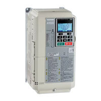
YASKAWA AC Drive-A1000 Technical Manual (534 pages)
High Performance Vector Control Drive
Brand:
YASKAWA
| Category:
Controller
| Size: 18.81 MB
Table of Contents
Quick Reference
3
Table of Contents
5
Preface & General Safety
15
Preface
16
Applicable Documentation
16
Symbols
16
I.1 Preface
16
Terms and Abbreviations
17
General Safety
18
Supplemental Safety Information
18
I.2 General Safety
18
Safety Messages
19
General Application Precautions
20
Motor Application Precautions
22
Drive Label Warnings
25
Warranty Information
25
1 Receiving
27
Section Safety
28
General Description
29
A1000 Model Selection
29
Control Mode Selection
30
Model Number and Nameplate Check
32
Nameplate
32
Drive Models and Enclosure Types
34
Component Names
35
IP20/NEMA Type 1 Enclosure
35
Front Views
36
2 Mechanical Installation
37
Section Safety
38
Mechanical Installation
40
Installation Environment
40
Installation Orientation and Spacing
40
Digital Operator Remote Usage
42
Exterior and Mounting Dimensions
45
3 Electrical Installation
47
Section Safety
48
Standard Connection Diagram
50
Main Circuit Connection Diagram
53
Three-Phase 600 V Class
53
Terminal Block Configuration
54
Terminal Cover
55
IP20/NEMA Type 1
55
Digital Operator and
56
Removing/Reattaching the Digital Operator
56
Removing/Reattaching the
56
Top Protective Cover
57
Removing the Top Protective Cover
57
Reattaching the Top Protective Cover
57
Main Circuit Wiring
58
Main Circuit Terminal Functions
58
Protecting Main Circuit Terminals
58
Wire Gauges and Tightening Torque
58
Main Circuit Terminal and Motor Wiring
59
Control Circuit Wiring
61
Control Circuit Connection Diagram
61
Control Circuit Terminal Block Functions
61
Terminal Configuration
63
Wiring the Control Circuit Terminal
65
Switches and Jumpers on the Terminal Board
67
Control I/O Connections
68
Sinking/Sourcing Mode Switch for Digital Inputs
68
Sinking/Sourcing Mode Selection for Safe Disable Inputs
69
Using the Pulse Train Output
69
Terminal A2 Input Signal Selection
70
Terminal A3 Analog/Ptc Input Selection
70
Terminal AM/FM Signal Selection
71
Memobus/Modbus Termination
71
Connect to a PC
72
External Interlock
73
Drive Ready
73
Wiring Checklist
74
4 Start-Up Programming & Operation
77
Section Safety
78
Using the Digital Operator
79
Keys and Displays
79
LCD Display
80
ALARM (ALM) LED Displays
81
LO/RE LED and RUN LED Indications
81
Menu Structure for Digital Operator
83
The Drive and Programming Modes
84
Navigating the Drive and Programming Modes
84
Changing Parameter Settings or Values
85
Verifying Parameter Changes: Verify Menu
87
YASKAWA ELECTRIC SIEP C710616 31B YASKAWA AC Drive - A1000 Technical Manual
87
Simplified Setup Using the Setup Group
88
Switching between LOCAL and REMOTE
89
Start-Up Flowcharts
91
Flowchart A: Basic Start-Up and Motor Tuning
92
Subchart A-1: Simple Motor Setup Using V/F Control
93
Subchart A-2: High Performance Operation Using OLV or CLV
94
Subchart A-3: Operation with Permanent Magnet Motors
95
Powering up the Drive
96
Powering up the Drive and Operation Status Display
96
Application Selection
97
Setting 1: Water Supply Pump Application
97
Setting 2: Conveyor Application
98
Setting 3: Exhaust Fan Application
98
Setting 4: HVAC Fan Application
98
Setting 5: Compressor Application
99
Auto-Tuning
100
Types of Auto-Tuning
100
Before Auto-Tuning the Drive
103
Auto-Tuning Interruption and Fault Codes
104
Auto-Tuning Operation Example
104
Parameter Settings During Induction Motor Auto-Tuning: T1
106
Parameter Settings During PM Motor Auto-Tuning: T2
108
Parameter Settings During Inertia and Speed Control Loop Auto-Tuning: T3
111
No-Load Operation Test Run
112
Test Run with Load Connected
114
Test Run with the Load Connected
114
Verifying Parameter Settings and Backing up Changes
115
Backing up Parameter Values: O2-03
115
Parameter Access Level: A1-01
115
Password Settings: A1-04, A1-05
115
Copy Function
116
Test Run Checklist
117
5 Parameter Details
119
A: Initialization
120
A1: Initialization
120
A2: User Parameters
125
B: Application
126
B1: Operation Mode Selection
126
B2: DC Injection Braking and Short Circuit Braking
133
B3: Speed Search
135
B4: Delay Timers
140
B5: PID Control
141
B6: Dwell Function
150
B7: Droop Control (CLV, CLV/PM)
151
B8: Energy Saving
152
B9: Zero Servo
153
C: Tuning
154
C1: Acceleration and Deceleration Times
154
C2: S-Curve Characteristics
156
C3: Slip Compensation
156
C4: Torque Compensation
159
C5: Automatic Speed Regulator (ASR)
161
C6: Carrier Frequency
166
D: Reference Settings
169
D1: Frequency Reference
169
D2: Frequency Upper/Lower Limits
171
D3: Jump Frequency
172
D4: Frequency Reference Hold and Up/Down 2 Function
173
D5: Torque Control
178
D6: Field Weakening and Field Forcing
182
D7: Offset Frequency
183
E: Motor Parameters
184
E1: V/F Pattern for Motor 1
184
E2: Motor 1 Parameters
187
E3: V/F Pattern for Motor 2
190
E4: Motor 2 Parameters
191
E5: PM Motor Settings
193
F: Option Settings
196
F1: PG Speed Control Card Settings
196
F2: Analog Input Card Settings
199
F3: Digital Input Card Settings
199
F4: Analog Monitor Card Settings
200
F5: Digital Output Card Settings
201
F6: Communication Option Card
201
CC-Link Parameters
203
PROFIBUS-DP Parameters
203
Canopen Parameters
204
Devicenet Parameters
204
H: Terminal Functions
207
H1: Multi-Function Digital Inputs
207
H2: Multi-Function Digital Outputs
218
H3: Multi-Function Analog Inputs
228
H4: Multi-Function Analog Outputs
234
H5: Memobus/Modbus Serial Communication
235
H6: Pulse Train Input/Output
235
L: Protection Functions
238
L1: Motor Protection
238
L2: Momentary Power Loss Ride-Thru
243
L3: Stall Prevention
250
L4: Speed Detection
256
L5: Fault Restart
257
L6: Torque Detection
259
L7: Torque Limit
261
L8: Drive Protection
263
N: Special Adjustments
269
N1: Hunting Prevention
269
N2: Speed Feedback Detection Control (AFR) Tuning
270
N3: High Slip Braking (HSB) and Overexcitation Braking
270
N5: Feed Forward Control
272
N6: Online Tuning
274
N8: PM Motor Control Tuning
275
O: Operator Related Settings
278
O1: Digital Operator Display Selection
278
O2: Digital Operator Keypad Functions
279
O3: Copy Function
281
O4: Maintenance Monitor Settings
282
Q: Driveworksez Parameters
283
R: Driveworksez Connection Parameters
283
T: Motor Tuning
283
U: Monitor Parameters
284
U1: Operation Status Monitors
284
U2: Fault Trace
284
U3: Fault History
284
U4: Maintenance Monitors
284
U5: PID Monitors
284
U6: Operation Status Monitors
284
U8: Driveworksez Monitors
285
6 Troubleshooting
287
Section Safety
288
Motor Performance Fine-Tuning
290
Fine-Tuning V/F Control and V/F Control with PG
290
Fine-Tuning Open Loop Vector Control
291
Fine-Tuning Closed Loop Vector Control
292
Fine-Tuning Open Loop Vector Control for PM Motors
292
Fine-Tuning Advanced Open Loop Vector Control for PM Motors
293
Fine-Tuning Closed Loop Vector Control for PM Motors
293
Parameters to Minimize Motor Hunting and Oscillation
294
Drive Alarms, Faults, and Errors
295
Types of Alarms, Faults, and Errors
295
Alarm and Error Displays
296
Fault Detection
300
Fault Displays, Causes, and Possible Solutions
300
Alarm Detection
316
Alarm Codes, Causes, and Possible Solutions
316
Operator Programming Errors
324
Operator Programming Error Codes, Causes, and Possible Solutions
324
Auto-Tuning Fault Detection
328
Auto-Tuning Codes, Causes, and Possible Solutions
328
Copy Function Related Displays
332
Tasks, Errors, and Troubleshooting
332
Diagnosing and Resetting Faults
334
Fault Occurs Simultaneously with Power Loss
334
If the Drive Still Has Power after a Fault Occurs
334
Viewing Fault Trace Data after Fault
334
Fault Reset Methods
335
Troubleshooting Without Fault Display
336
Common Problems
336
Cannot Change Parameter Settings
336
Motor Does Not Rotate Properly after Pressing RUN Button or after Entering External Run Command
337
Motor Is too Hot
338
Drive Does Not Allow Selection the Desired Auto-Tuning Mode
339
Ope02 Error Occurs When Lowering the Motor Rated Current Setting
339
Motor Stalls During Acceleration or Acceleration Time Is too Long
339
Drive Frequency Reference Differs from the Controller Frequency Reference Command
340
Excessive Motor Oscillation and Erratic Rotation
340
Deceleration Takes Longer than Expected with Dynamic Braking Enabled
340
Noise from Drive or Output Lines When the Drive Is Powered on
341
Ground Fault Circuit Interrupter (GFCI) Trips During Run
341
Connected Machinery Vibrates When Motor Rotates
341
PID Output Fault
342
Insufficient Starting Torque
342
Motor Rotates after the Drive Output Is Shut off (Motor Rotates During DC Injection Braking)
342
Output Frequency Is Not as High as Frequency Reference
342
Buzzing Sound from Motor at 2 Khz
342
Unstable Motor Speed When Using PM
343
Motor Does Not Restart after Power Loss
343
7 Periodic Inspection & Maintenance
345
Section Safety
346
Inspection
348
Recommended Daily Inspection
348
Recommended Periodic Inspection
349
Periodic Maintenance
351
Replacement Parts
351
Drive Cooling Fans
353
Number of Cooling Fans
353
Cooling Fan Component Names
353
Cooling Fan Replacement
353
Drive Replacement
356
Serviceable Parts
356
Terminal Board
356
Replacing the Drive
356
8 Peripheral Devices & Options
359
Section Safety
360
Drive Options and Peripheral Devices
361
Connecting Peripheral Devices
363
Option Card Installation
364
Installing Option Cards
364
Installation Procedure
364
Installing Peripheral Devices
366
Dynamic Braking Options
366
Installing a Molded Case Circuit Breaker (MCCB) and Earth Leakage Circuit Breaker (ELCB)
367
Installing a Ground Fault Circuit Interrupter (GFCI)
367
Installing a Magnetic Contactor at the Power Supply Side
368
Connecting an AC or DC Reactor
368
Installing Input Fuses
369
Attachment for External Heatsink Mounting
369
Installing a Motor Thermal Overload (Ol) Relay on the Drive Output
369
Specifications
371
Heavy Duty and Normal Duty Ratings
372
Power Ratings
373
Three-Phase 600 V Class Drives
373
Drive Specifications
374
Drive Watt Loss Data
376
Drive Derating Data
377
Carrier Frequency Derating
377
Temperature Derating
377
Altitude Derating
378
Parameter List
379
Understanding Parameter Descriptions
380
Control Modes, Symbols, and Terms
380
Parameter Groups
381
A: Initialization Parameters
382
A1: Initialization
382
A2: User Parameters
383
B: Application
384
B1: Operation Mode Selection
384
B2: DC Injection Braking and Short Circuit Braking
385
B3: Speed Search
386
B4: Timer Function
387
B5: PID Control
387
B6: Dwell Function
389
B7: Droop Control
389
B8: Energy Saving
389
B9: Zero Servo
390
C: Tuning
391
C1: Acceleration and Deceleration Times
391
C2: S-Curve Characteristics
392
C3: Slip Compensation
392
C4: Torque Compensation
393
C5: Automatic Speed Regulator (ASR)
393
C6: Carrier Frequency
395
D: References
397
D1: Frequency Reference
397
D2: Frequency Upper/Lower Limits
398
D3: Jump Frequency
398
D4: Frequency Reference Hold and Up/Down 2 Function
399
D5: Torque Control
400
D6: Field Weakening and Field Forcing
400
D7: Offset Frequency
401
E: Motor Parameters
402
E1: V/F Pattern for Motor 1
402
E2: Motor 1 Parameters
403
E3: V/F Pattern for Motor 2
404
E4: Motor 2 Parameters
405
E5: PM Motor Settings
406
F: Options
407
F1: PG Speed Control Card (PG-B3/PG-X3)
407
F2: Analog Input Card (AI-A3)
409
F3: Digital Input Card (DI-A3)
409
F4: Analog Monitor Card (AO-A3)
410
F5: Digital Output Card (DO-A3)
410
F6: Communication Option Card
411
H Parameters: Multi-Function Terminals
414
H1: Multi-Function Digital Inputs
414
H2: Multi-Function Digital Outputs
419
H3: Multi-Function Analog Inputs
422
H4: Analog Outputs
424
H5: Memobus/Modbus Serial Communication
425
H6: Pulse Train Input/Output
426
L: Protection Function
427
L1: Motor Protection
427
L2: Momentary Power Loss Ride-Thru
427
L3: Stall Prevention
429
L4: Speed Detection
430
L5: Fault Restart
431
L6: Torque Detection
431
L7: Torque Limit
433
L8: Drive Protection
433
N: Special Adjustment
436
N1: Hunting Prevention
436
N2: Speed Feedback Detection Control (AFR) Tuning
436
N3: High Slip Braking (HSB) and Overexcitation Braking
436
N5: Feed Forward Control
437
N6: Online Tuning
438
N8: PM Motor Control Tuning
438
O: Operator-Related Settings
440
O1: Digital Operator Display Selection
440
O2: Digital Operator Keypad Functions
440
O3: Copy Function
441
O4: Maintenance Monitor Settings
441
Driveworksez Parameters
443
Q: Driveworksez Parameters
443
R: Driveworksez Connection Parameters
443
T: Motor Tuning
444
T1: Induction Motor Auto-Tuning
444
T2: PM Motor Auto-Tuning
445
T3: ASR and Inertia Tuning
447
U: Monitors
448
U1: Operation Status Monitors
448
U2: Fault Trace
450
U3: Fault History
451
U4: Maintenance Monitors
452
U5: PID Monitors
453
U6: Operation Status Monitors
454
U8: Driveworksez Monitors
455
Control Mode Dependent Parameter Default Values
456
A1-02 (Motor 1 Control Mode) Dependent Parameters
456
E3-01 (Motor 2 Control Mode) Dependent Parameters
458
V/F Pattern Default Values
459
Defaults by Drive Model (O2-04) and ND/HD (C6-01)
460
Memobus/Modbus Communications
463
Memobus/Modbus Configuration
464
Communication Specifications
465
Connecting to a Network
466
Network Cable Connection
466
Wiring Diagram for Multiple Connection
466
Network Termination
467
Memobus/Modbus Setup Parameters
468
Memobus/Modbus Serial Communication
468
Drive Operations by Memobus/Modbus
471
Observing the Drive Operation
471
Controlling the Drive
471
Communications Timing
472
Command Messages from Master to Drive
472
Response Messages from Drive to Master
472
Message Format
473
Message Content
473
Slave Address
473
Function Code
473
Data
473
Error Check
473
Message Examples
475
Reading Drive Memobus/Modbus Register Contents
475
Loopback Test
475
Writing to Multiple Registers
476
Memobus/Modbus Data Table
477
Command Data
477
Monitor Data
478
Broadcast Messages
488
Fault Trace Contents
489
Alarm Register Contents
491
Enter Command
492
Enter Command Types
492
Enter Command Settings When Upgrading the Drive
492
Communication Errors
493
Memobus/Modbus Error Codes
493
Slave Not Responding
493
Self-Diagnostics
494
Standards Compliance
495
Section Safety
496
UL Standards
498
UL Standards Compliance
498
Drive Motor Overload Protection
499
Safe Disable Input Function
501
Specifications
501
Precautions
501
Using the Safe Disable Function
501
Quick Reference Sheet
505
Drive and Motor Specifications
506
Drive Specifications
506
Motor Specifications
506
Basic Parameter Settings
507
Basic Setup
507
V/F Pattern Setup
507
Motor Setup
507
Multi-Function Digital Inputs
507
Pulse Train Input/Analog Inputs
508
Multi-Function Digital Outputs
508
Monitor Outputs
508
User Setting Table
509
Index
517
Advertisement
Advertisement
Related Products
YASKAWA DI-A3
YASKAWA DI-101
YASKAWA DO-A3
YASKAWA Varispeed DI-16H2
YASKAWA Drive-V1000
YASKAWA DR2
YASKAWA MOTOMAN DX100
YASKAWA Motoman DX200
Yaskawa D Series
YASKAWA SGDV DE5A Series
YASKAWA Categories
Controller
DC Drives
Servo Drives
Robotics
Control Unit
More YASKAWA Manuals
Login
Sign In
OR
Sign in with Facebook
Sign in with Google
Upload manual
Upload from disk
Upload from URL