Sign In
Upload
Manuals
Brands
Omron Manuals
Network Hardware
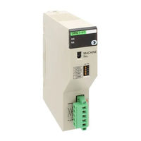
DeviceNet CVM1-DRM21-V1
Omron DeviceNet CVM1-DRM21-V1 Master Unit Manuals
Manuals and User Guides for Omron DeviceNet CVM1-DRM21-V1 Master Unit. We have
2
Omron DeviceNet CVM1-DRM21-V1 Master Unit manuals available for free PDF download: Operation Manual
Omron DeviceNet CVM1-DRM21-V1 Operation Manual (379 pages)
DeviceNet Slaves
Brand:
Omron
| Category:
Network Hardware
| Size: 6 MB
Table of Contents
Precautions
12
Table of Contents
12
Intended Audience
13
General Precautions
13
Safety Precautions
13
Operating Environment Precautions
13
Application Precautions
14
EC Directives
15
Devicenet Manuals
16
Drt1-Id08-1
25
Drt1-Id16-1
25
Drt1-Od08
25
Drt1-Od08-1
25
Section 2 Example System Setup
30
Basic Procedures and Configuration Examples
31
Basic Procedures
31
System Configuration Example
32
Preparations
32
Setting and Wiring Hardware
33
Mounting and Setting the Master Unit
33
Mounting and Setting Slaves
34
Mounting Connecting Devices
35
Connecting Cables
36
Starting Communications
37
Creating I/O Tables for the Master Unit
37
Starting the System
37
Creating and Registering Scan Lists
38
Checking Operations
41
Indicator Status
41
Reading and Writing Data
41
Section 4 General-Purpose Slaves
48
Common Specifications for General-Purpose Slaves
50
Current Consumption and Weight
50
Connecting Communications Cables to General-Purpose Slaves
51
Connecting Communications Cables
51
Connecting Communications Cables to the Nodes
54
Mounting Terminating Resistors
56
Transistor Remote I/O Terminals
57
Node Address, Baud Rate, and Output Hold/Clear Settings
57
Transistor Remote Input Terminals with 8 Points: DRT1-ID08 (NPN) and DRT1-ID08-1 (PNP)
58
Transistor Remote Input Terminals with 16 Points: DRT1-ID16 (NPN) and DRT1-ID16-1 (PNP)
62
Transistor Remote Output Terminals with 8 Points: DRT1-OD08 (NPN) and DRT1-OD08-1 (PNP)
66
Transistor Remote Output Terminals with 16 Points: DRT1-OD16 (NPN) and DRT1-OD16-1 (PNP)
70
Drt1-Od16
70
Drt1-Od16-1
70
Transistor Remote I/O Terminal with 8 Inputs and 8 Outputs: DRT1-MD16 (NPN)
73
Drt1-Md16
73
Mounting in Control Panels
76
Wiring Internal Power Supplies, I/O Power Supplies, and I/O Lines
77
Transistor Remote I/O Terminals with 3-Tier I/O Terminal Blocks
79
Node Address, Baud Rate, and Output Hold/Clear Settings
79
Transistor Remote Input Terminals with 16 Points and 3-Tier I/O Terminal Blocks: DRT1-ID16T (NPN) and DRT1-ID16T-1 (PNP)
80
Drt1-Id16T Drt1-Id16T-1
80
Transistor Remote Input Terminals with 16 Points and 3-Tier I/O Terminal Blocks: DRT1-ID16TA (NPN) and DRT1-ID16TA-1 (PNP)
84
Transistor Remote Output Terminals with 16 Points and 3-Tier I/O Terminal Blocks: DRT1-OD16T (NPN) and DRT1-OD16T-1 (PNP)
87
Transistor Remote Output Terminals with 16 Points and 3-Tier I/O Terminal Blocks: DRT1-OD16TA (NPN) and DRT1-OD16TA-1 (PNP)
90
Transistor Remote I/O Terminals with 8 Inputs and 8 Outputs and 3-Tier I/O Terminal Blocks: DRT1-MD16T (NPN) and DRT1-MD16T-1 (PNP)
94
Transistor Remote I/O Terminals with 8 Inputs and 8 Outputs and 3-Tier I/O Terminal Blocks: DRT1-MD16TA (NPN) and DRT1-MD16TA-1 (PNP)
98
Mounting in Control Panels
102
Wiring Internal Power Supplies, I/O Power Supplies, and I/O Lines
103
Transistor Remote I/O Terminals with Connectors
104
Node Address, Baud Rate, and Output Hold/Clear Settings
104
Transistor Remote Input Terminals with 32 Points and Connectors
105
DRT1-ID32ML (NPN) and DRT1-ID32ML-1 (PNP)
105
Transistor Remote Output Terminals with 32 Points and Connectors
110
DRT1-OD32ML (NPN) and DRT1-OD32ML-1 (PNP)
110
Transistor Remote I/O Terminals with
111
DRT1-MD32ML (NPN) and DRT1-MD32ML-1 (PNP)
116
Mounting in Control Panels
120
Wiring Internal Power Supplies, I/O Power Supplies and I/O
125
Remote Adapters
128
Node Address, Baud Rate, and Output Hold/Clear Settings
128
Remote Input Adapters with 16 Points
129
DRT1-ID16X (NPN) and DRT1-ID16X-1 (PNP)
129
Remote Output Adapters with 16 Points
134
DRT1-OD16X (NPN) and DRT1-OD16X-1 (PNP)
134
Mounting in Control Panels
139
Wiring Internal Power Supplies, I/O Power Supplies, and I/O Lines
139
Sensor Terminals
141
Node Address, Baud Rate, and Output Hold/Clear Settings
141
Transistor Input Sensor Terminals with 16 Points: DRT1-HD16S
142
Transistor I/O Sensor Terminals with 8 Inputs and 8 Outputs: DRT1-ND16S
146
Mounting in Control Panels
149
Wiring Internal Power Supplies, I/O Power Supplies, and I/O Lines
150
Analog I/O Terminals
153
Node Address and Baud Rate Setting
153
Analog Input Terminals: DRT1-AD04 and DRT1-AD04H
154
Analog Output Terminal: DRT1-DA02
166
Mounting in Control Panels
173
Wiring Internal Power Supplies and I/O Lines
173
Temperature Input Terminals
174
Node Address and Baud Rate Settings
174
Temperature Input Terminals: DRT1-TS04T and DRT1-TS04P
175
Mounting in Control Panels
186
Wiring Internal Power Supplies and I/O Lines
187
4-10 CQM1 I/O Link Unit
188
Node Address, Baud Rate, and Output Hold/Clear Settings
188
CQM1 I/O Link Unit: CQM1-DRT21
190
4-10-3 Mounting to Control Panels
191
Section 5 Environment-Resistive and Waterproof Slaves
192
Environment-Resistive Slave Specifications
193
Current Consumption, Weight, Degree of Protection
193
Environment-Resistive Slaves
193
Connecting Communications Cables to Environment-Resistive Slaves
194
Example System Assembly
196
Environment-Resistive Terminals (IP66)
196
Node Address and Baud Rate Settings
196
Environment-Resistive Terminal (IP66) with 8 Transistor Inputs: DRT1-ID08C (NPN)
197
Environment-Resistive Terminal (IP66) with 16 Transistor Inputs: DRT1-HD16C (NPN) and DRT1-HD16C-1 (PNP)
200
Environment-Resistive Terminal (IP66) with 8 Transistor Outputs: DRT-OD08C (NPN)
204
Environment-Resistive Terminal (IP66) with 16 Transistor Outputs: DRT1-WD16C (NPN) and DRT1-WD16C-1 (PNP)
206
Environment-Resistive Terminal (IP66) with 8 Inputs 8 Outputs: DRT1-MD16C (NPN) and DRT1-MD16C-1 (PNP)
210
Mounting in Control Panels
214
Wiring Internal Power Supplies, I/O Power Supplies, and I/O Lines
215
Waterproof Terminals (IP67)
217
Node Address, Baud Rate, and Output Hold/Clear Settings
217
Waterproof Terminal (IP67) with 4 Transistor Inputs: DRT1-ID04CL (NPN) and DRT1-ID04CL-1 (PNP)
219
Waterproof Terminal (IP67) with 8 Transistor Inputs: DRT1-ID08CL (NPN) and DRT1-ID08CL-1 (PNP)
221
Waterproof Terminal (IP67) with 4 Transistor Outputs: DRT1-OD04CL (NPN) and DRT1-OD04CL-1 (PNP)
224
Waterproof Terminal (IP67) with 8 Transistor Outputs: DRT1-OD08CL (NPN) and DRT1-OD08CL-1 (PNP)
227
Mounting in Control Panels
230
Wiring Internal Power Supplies, I/O Power Supplies, and I/O Lines
230
B7AC Interface Units
232
Node Address and Baud Rate Settings (DIP Switch 1)
232
Example System Configuration
234
B7AC Interface Unit: DRT1-B7AC
234
Mounting in Control Panels
240
Wiring the Internal Power Supply and Input Lines
241
Section 6 Special I\/O Slave Units Specifications
246
C200H I/O Link Units
247
Communications Cable Connections
247
Node Address Setting (Rear DIP Switch)
247
Baud Rate and Hold/Clear Write Area Settings (Front DIP Switch)
248
Specifications
248
Components
249
Rotary Switch Settings
251
Special I/O Area Function and Read/Write Area Allocation
252
Explicit Devicenet Messages
260
Using Explicit Devicenet Messages
267
6-1-10 Dimensions
273
6-1-11 Installing in a Control Panel
273
6-1-12 C200H I/O Link Unit Application Examples
273
RS-232C Units
277
Communications Cable Connections
277
Node Address and Baud Rate Settings
277
Specifications
279
Components
280
Word Allocations for Communications Status
282
Using the RS-232C Unit
283
Explicit Devicenet Messages
286
Using Explicit Devicenet Messages
297
Dimensions
302
6-2-10 Mounting in Control Panels
302
6-2-11 Wiring
303
6-2-12 RS-232C Unit Application Examples
305
6-2-13 Reading RS-232C Unit Parameters
309
6-2-14 Reading Data Received by RS-232C Unit Ports
311
Drt1-Id16Ta Drt1-Id16Ta-1
341
Drt1-Id32Ml Drt1-Id32Ml-1
341
Drt1-Md16T Drt1-Md16T-1
341
Drt1-Md16Ta Drt1-Md16Ta-1
341
Drt1-Md32Ml Drt1-Md32Ml-1
341
Drt1-Od16T Drt1-Od16T-1
341
Drt1-Od16Ta Drt1-Od16Ta-1
341
Drt1-Od32Ml Drt1-Od32Ml-1
341
0Eget_Attribute_Single
344
10Set_Attribute_Single
346
Appendix B
347
Model Produced Connection Size
348
Advertisement
Omron DeviceNet CVM1-DRM21-V1 Operation Manual (286 pages)
DeviceNet Master Units
Brand:
Omron
| Category:
Industrial Equipment
| Size: 3 MB
Table of Contents
OMRON Product References
4
Visual Aids
4
Trademarks and Copyrights
4
Table of Contents
6
Read and Understand this Manual
12
Warranty and Limitations of Liability
12
Application Considerations
13
Precautions
16
Intended Audience
17
General Precautions
17
Safety Precautions
17
Operating Environment Precautions
18
Application Precautions
19
EC Directives
20
Features and System Configuration
22
Overview of Devicenet
23
Introduction
23
Master Unit Models
25
Devicenet Functions of OMRON Master Units
25
Types of Slaves
29
Devicenet Configurator
36
Devicenet Network Features
37
Reduced Wiring
37
Multi-Vendor Networks
37
Remote I/O Communications and Message Communications
38
Device Profiles
38
Devicenet Master Unit Version Comparison
39
Specifications
39
Devicenet Master Units
39
Overview of Configurator Usage
43
Basic Operating Procedures
47
Devicenet Network Setup Flowchart
47
Hardware Preparations
48
Setting up Communications
48
Startup Procedure
50
Operations Listed by Category
52
Master Unit Components and Installation
54
Master Unit for CVM1 and CV-Series Plcs
55
Component Names and Functions
55
Switch Settings
56
Master Unit Mounting Restrictions
58
Dimensions
58
Master Units for C200HX/HG/HE and C200HS Plcs
59
Component Names and Functions
59
Switch Settings
60
Master Unit Mounting/Usage Restrictions
62
Mounting Devicenet Master Units
64
Mounting the Master Units
64
Mounting T-Branch Taps and Terminating Resistors
65
Remote I/O Communications
66
Overview of the Remote I/O Functions
67
Introduction
67
Scan Lists
74
Default Remote I/O Allocation
75
PLC Allocation Areas
75
I/O Allocation and Errors
77
Slave Models and I/O Allocations
79
Default Remote I/O Allocation Example
81
Basic Application Procedure
81
Actual System Allocation Example
83
User-Set Allocations
85
Allocation Method
85
Example of User-Set Allocations
88
Basic Application Procedure
89
Actual System Allocation Example
91
Devicenet Remote I/O Communications
95
Overview of Remote I/O Allocations for Smart Slaves
95
I/O Allocations for Smart Slaves
97
Message Communications
102
Overview
103
Message Communications Specifications
106
FINS Commands/Responses
108
Sending/Receiving FINS Command/Responses
108
Units Supporting FINS Communications
110
FINS Command Lists
110
Message Communications for CVM1 and CV-Series Plcs
112
Instructions for Message Communications
112
Data Send/Receive Instructions
113
Sending FINS Commands
115
Using SEND(192), RECV(193), and CMND(194
117
Programming Examples
119
Message Communications for CS-Series and C200HX/HG/HE Plcs
122
Instructions for Message Communications
122
Sending FINS Commands
122
Using IOWR
126
C200HX/HG/HE Programming Example: Sending a FINS Command
129
Sending Explicit Messages
132
FINS Command: EXPLICIT MESSAGE SEND (28 01)
134
Programming Examples
136
Software Switches and Status Area
142
Software Switch/Status Area Location
143
Software Switches
144
Software Switch Functions
144
Status Area
146
Status Area Configuration
146
Master Status Area 1
148
Master Status Area 2
151
Current Communications Cycle Time
151
Using the Status Area in Programming
151
Registered Slave Data
152
Normal Slave Data
153
Communications Timing
154
Remote I/O Communications Characteristics
155
Communications Cycle Time and Refresh Time
155
I/O Response Time
157
More than One Master in Network
163
System Startup Time
164
Message Communications Time
165
Troubleshooting and Maintenance
168
Indicators and Error Processing
169
Master Unit Indicators
169
MS and NS Indicators
169
Seven-Segment Display
169
Identifying Errors from the Indicators
171
Errors Occurring in the Master Unit
172
Error Log Function
176
Introduction
176
Error Log Data
176
Error Codes
177
FINS Commands for Error Logs
178
Programming Examples
178
Troubleshooting
187
Master Unit Troubleshooting
187
Maintenance
191
Cleaning
191
Inspection
191
Replacing Nodes
191
FINS Commands to CVM1 and CV-Series CPU Units
194
Command List
196
Memory Area Designations
197
Word/Bit Addresses
199
Volume Labels and File Names
200
Data Configurations
200
Memory Area Read
201
Memory Area Write
202
Memory Area Fill
203
Multiple Memory Area Read
204
Memory Area Transfer
205
Composite Registration Read
206
Register Composite Read
207
Parameter Area Read
208
Parameter Area Write
210
Parameter Area Clear
211
Program Area Protect
212
Program Area Protect Clear
213
Program Area Read
213
Program Area Write
214
Program Area Clear
215
Run
215
Stop
216
Controller Data Read
216
Connection Data Read
219
Controller Status Read
220
Cycle Time Read
221
Clock Read
222
Clock Write
223
Message Read
223
Message Clear
224
Fal/Fals Read
225
Access Right Acquire
226
Access Right Forced Acquire
227
Access Right Release
227
Error Clear
228
Error Log Read
229
Error Log Clear
230
File Name Read
230
Single File Read
232
Single File Write
232
Memory Card Format
233
File Delete
234
Volume Label Create/Delete
234
File Copy
235
File Name Change
235
File Data Check
236
Memory Area File Transfer
237
Parameter Area File Transfer
238
Program Area File Transfer
239
Forced Set/Reset
240
Forced Set/Reset Cancel
241
FINS Commands to CS-Series and C200HX/HG/HE CPU Units
244
Command List
245
Memory Area Designations
245
Word/Bit Addresses
246
Memory Area Read
247
Data Configuration
247
Memory Area Write
248
Multiple Memory Area Read
249
Composite Registration Read
250
Register Composite Read
250
Controller Data Read
251
Controller Status Read
252
Clock Read
252
FINS Commands to Devicenet Master Units
254
Command List
255
Reset
255
Controller Data Read
255
Echoback Test
256
Error Log Read
256
Error Log Clear
258
Sending Explicit Messages to Devicenet Devices by Other Manufacturers
260
FINS Command Response Codes
262
Response Codes and Troubleshooting
262
Node Address Settings Table
270
Connecting Another Company's Slaves
272
Master Unit Device Profile
274
Glossary
276
Index
278
Revision History
284
Advertisement
Related Products
Omron CVM1-CLK21
Omron C200HW-CLK21
Omron CJ1W-CLK21-V1
Omron CS1W-CLK21-V1
Omron CS1W-ETN11
OMRON CQM1H-SCB41
Omron CS/CJ Series
Omron SYSMAC CJ2H-CPU6@-EIP
Omron SYSMAC CJ2M-CPU3 Series
OMRON CJ1W-EIP21 - 10-2010
Omron Categories
Blood Pressure Monitor
Controller
Accessories
Switch
Inverter
More Omron Manuals
Login
Sign In
OR
Sign in with Facebook
Sign in with Google
Upload manual
Upload from disk
Upload from URL