Sign In
Upload
Manuals
Brands
Mircom Manuals
Telephone System
TX3-1000-8U
Mircom TX3-1000-8U Access System Manuals
Manuals and User Guides for Mircom TX3-1000-8U Access System. We have
4
Mircom TX3-1000-8U Access System manuals available for free PDF download: Installation And Operation Manual, Programming Manual
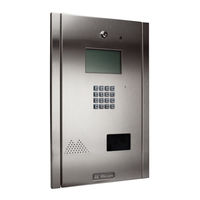
Mircom TX3-1000-8U Installation And Operation Manual (119 pages)
TELEPHONE ACCESS SYSTEMS
Brand:
Mircom
| Category:
Intercom System
| Size: 6 MB
Table of Contents
Table of Contents
3
Figure
6
1 Introduction
8
TX3 Systems
9
Features
10
Lobby Control Unit Enclosures
11
Lobby Control Unit Accessories
17
Mounting Requirements from the 2010 ADA Standards for Accessible Design
17
Warranty and Special Notices
18
About this Manual
19
Version
19
Contact Us
20
2 Enclosure Installation
22
Grounding the Telephone Access System
23
Installing the Enclosures and Lobby Control Unit
23
Figure 1 TX3-UFT Universal Series Flush Trim Ring
24
Figure
26
Figure 2 TX3-USFT Slim Line Universal Flush Trim Ring
27
Figure 3 Continental Enclosure Flush Mount
28
Installing the Heater
29
Figure 4 Heater TH-102 Installation Location
29
Figure 5 Dimensions of the 8 Line Kiosk (Inches)
30
TX3-2000-8K-A Installation
30
Figure 6 Reinforcement Bracket with Bolts
31
Figure 7 Reinforcement Bracket with Nuts
32
Figure 8 Kiosk Base Plate with Bolts
32
Figure 9 Kiosk Mounting Holes
32
Figure 10 Base Plate Mounting Holes
33
Figure 11 Base Plate Dimensions (Inches)
33
Figure 12 Fitting the Kiosk on the Base Plate
34
Figure 13 Fitting the Kiosk on the Base Plate (from Below)
34
Figure 14 Attach the Kiosk to the Base Plate
35
3 TX3 System
36
TX3 System
37
Single Lobby Control Unit
38
Figure 15 Single Lobby Control Unit
38
Figure 16 Single Lobby Control Unit with ADC and NSL Lines
39
Dual Lobby Control Units
40
Figure 17 Single Entrance System Wiring
40
Three Lobby Control Unit Configuration
41
Figure 18 Dual Lobby Control Units
41
Figure 19 Multiple Lobby Control Units to Multiple Lines
42
Multiple Lobby Control Units
43
Figure 20 Many Lobby Control Units to One Line
43
Networking TX3 Panels
44
Figure 21 TX3 Devices on an RS-485 Network
44
Figure 22 TX3 Devices on an Ethernet TCP/IP Network
45
Figure 23 Lobby Control Units Using both Ethernet and
46
Lobby Control Unit Wiring
47
Figure 24 Lobby Control Unit Wiring
47
4 Lobby Control Unit Setup
48
Controller Board
49
Figure 25 Lobby Control Unit Main Controller Board
49
Controller Board Connectors - Bottom
51
Figure 27 Controller Board Connectors - Bottom
51
Figure 28 Tamper Switch
53
Figure 29 RS-485 Connections
53
Figure 30 Power Supply
54
Controller Board Connectors - Top
55
Figure 31 Controller Board Connectors - Top
55
Figure 32 Main Door Dry Contact Wiring
57
Modem Module
58
Figure 33 Modem Module Telephone Connectors
58
TX3-IP IP Module
59
RS-485 Add-On Module
59
Figure 34 IP Module Data and Ethernet Connectors
59
Guard Phone Module
60
Figure 35 RS-485 Add-On Module
60
Table 1 RS-485 Add-On Jumper Settings
60
Guard Phone
61
Figure 36 Guard Phone Module
61
Controller ID Setup
62
Table 2 Lobby Control Unit SW1 DIP Switch Settings
63
Configuration Using a PC
65
Updating Firmware
66
Beginning Configuration
66
5 NSL Relay Cabinet Installation and Wiring
68
NSL Relay Cabinet Mechanical Installation
69
Figure 37 NSL Relay Cabinet
69
NSL Relay Control Unit and Expanders
70
Table 3 NSL Relay Cabinet Dimensions
70
Figure 38 TX3-NSL-8M Relay Control Unit
71
LT-969 Copyright January
71
Figure 39 NSL Expanders
72
Wiring the TX3-NSL-8M Main Controller Board
73
Figure 40 TX3-NSL-8M Main Controller Board
73
Figure 41 NSL System with Telephone Line
75
Figure 42 NSL Controller Telephone Lines
76
Figure 43 NSL Backplane
78
Figure 44 ADSL-100 Filter Module Installation
79
Figure 45 Backplane Number Section
80
Table 4 Sample Backplane Relay Addresses
81
Figure 46 2012 NSL Relay Board
83
Figure 47 CA-71A BIX Block Wiring Configuration
84
Table 5 CA-71A BIX Block Identification Form
85
Figure 48 RJ-71C Punch-Down Block Wiring Configuration
87
Table 6 RJ-71C Punch-Down Block Identification Form
88
Updating Firmware
90
6 Elevator Restriction Unit Installation and Configuration
91
Elevator Restriction Cabinet Mechanical Installation
92
Figure 49 Elevator Relay Cabinet
92
Elevator Restriction Units
94
Figure 50 Lobby Control Unit with Elevator Restriction
94
Figure 51 Elevator Restriction Unit
95
Wiring the Elevator Restriction Unit
96
Figure 52 Elevator Controller Board
96
Figure 53 Elevator Restriction Controller Board Wiring
98
Elevator Restriction Controller Backplane
99
Figure 54 Elevator Restriction Controller Backplane
99
2012E Elevator Restriction Relay Card
100
Figure 55 2012E Elevator Restriction Relay Board
100
Elevator Restriction Unit Configuration
101
Table 7 Lobby Control Unit SW2 DIP Switch Settings
101
Updating Firmware
103
7 Adding Controllers
104
Adding a Controller
105
8 Appendix
106
Specifications
107
9 Resident Operating Instructions
109
NSL Resident Operating Instructions
110
ADC Resident Operating Instructions
112
Warranty & Warning Information
113
Special Notices
116
Telephone Access System Installation and Operation Manual Version 3.7 LT-969 Copyright January
117
Advertisement
Mircom TX3-1000-8U Installation And Operation Manual (112 pages)
TX3 Series TELEPHONE ACCESS SYSTEMS
Brand:
Mircom
| Category:
Telephone System
| Size: 4 MB
Table of Contents
Table of Contents
3
1 Introduction
9
TX3 Systems
10
Features
11
Lobby Control Unit Enclosures
12
Lobby Control Unit Accessories
14
Warranty and Special Notices
15
About this Manual
15
Contact Us
16
2 Enclosure Installation
19
Grounding the Telephone Access System
20
Installing the Enclosures and Lobby Control Unit
20
Figure 1. TX3-UFT Universal Series Flush Trim Ring
21
Figure 2. TX3-USFT Slim Line Universal Flush Trim Ring
24
Figure 3. Continental Enclosure Flush Mount
25
Installing the Heater
26
Figure 4. Heater TH-102 Installation Location
26
3 TX3 System
27
TX3 System
28
Single Lobby Control Unit
29
Figure 5. Single Lobby Control Unit
29
Figure 6. Single Lobby Control Unit with ADC and NSL Lines
30
Dual Lobby Control Units
31
Figure 7. Single Entrance System Wiring
31
Three Lobby Control Unit Configuration
32
Figure 8. Dual Lobby Control Units
32
Figure 9. Multiple Lobby Control Units to Multiple Lines
33
Multiple Lobby Control Units
34
Lobby Control Unit Wiring
34
Figure 10. Many Lobby Control Units to One Line
34
Figure 11. Lobby Control Unit Wiring
35
4 Lobby Control Unit Setup
37
Controller Board
38
Figure 12.Lobby Control Unit Main Controller Board
38
Controller Board Connectors - Bottom
40
Figure 13.Controller Board Connectors - Bottom
40
Figure 14.Tamper Switch
41
Figure 15.Connecting Additional RS-485 Terminal Connector to the First or Last Node of Network
42
Figure 16. Power Supply
43
Controller Board Connectors - Top
44
Figure 17.Controller Board Connectors - Top
44
Figure 18.Main Door Dry Contact Wiring
45
Modem Board
46
MD-993 Module
47
Figure 19.Modem Module Telephone Connectors
47
Figure 20. MD-993 Module
47
Guard Phone Module
48
Figure 21.Guard Phone Module
48
MD-933 Jumper Settings
48
Guard Phone
49
Controller ID Setup
49
Table 2: Lobby Control Unit SW1 DIP Switch Settings
50
Configuration Using a PC
51
Updating Firmware
52
Figure 22. Firmware Upgrade
53
Figure 23. Firmware Upgrade - Erasing Current Firmware
54
Figure 24. Firmware Upgrade - Program New Firmware
55
Beginning Configuration
56
5 NSL Relay Cabinet Installation and Wiring
57
NSL Relay Cabinet Mechanical Installation
58
Figure 25. NSL Relay Cabinet
58
NSL Relay Control Unit and Expanders
59
Table 3: NSL Relay Cabinet Dimensions
59
Figure 26. TX3-NSL-8M Relay Control Unit
60
Figure 27. NSL Expanders
61
Wiring the TX3-NSL-8M Main Controller Board
62
Figure 28. TX3-NSL-8M Main Controller Board
62
Figure 29. NSL System with Telephone Line
64
Figure 30. NSL Controller Telephone Lines
64
Figure 31. NSL Backplane
66
Figure 32. ADSL-100 Filture Module Installation
67
Figure 33. Backplane Number Section
68
Table 4: Sample Backplane Relay Addresses
69
Figure 34. 2012 NSL Relay Board
71
Figure 35. CA-71A BIX Block Wiring Configuration
72
Table 5: CA-71A BIX Block Identification Form
74
Figure 36. RJ-71C Punch-Down Block Wiring Configuration
75
Table 6: RJ-71C Punch-Down Block Identification Form
76
Updating Firmware
78
LT-969 Copyright
79
6 Elevator Restriction Unit Installation and Configuration
79
Elevator Restriction Cabinet Mechanical Installation
80
Figure 37. Elevator Relay Cabinet
80
TX3-ER-8 Elevator Restriction Units
81
Figure 38. Lobby Control Unit with Elevator Restriction
81
Figure 39. TX3-ER-8 Elevator Restriction Unit
82
Wiring the TX3-ER-8 Elevator Restriction Unit
83
Figure 40. Elevator Controller Board
83
Figure 41. Elevator Restriction Controller Board Wiring
85
Elevator Restriction Controller Backplane
86
Figure 42. Elevator Restriction Controller Backplane
86
2012E Elevator Restriction Relay Card
87
Figure 43. 2012E Elevator Restriction Relay Board
87
TX3-ER-8 Elevator Restriction Unit Configuration
88
Table 7: Lobby Control Unit SW1 DIP Switch Settings
88
LT-969 Copyright
88
Updating Firmware
90
7 Adding Controllers
91
Adding a Controller
92
8 Appendix
93
Specifications
94
Kits - Electronic Scrolling Directory
96
Kits - Telephone Access Slim-Line
97
Kits - Continental Series Enclosures
98
9 Resident Operating Instructions
101
NSL Resident Operating Instructions
102
ADC Resident Operating Instructions
104
Warranty & Warning Information
105
Warranty Procedure
106
Special Notices
108
Mircom TX3-1000-8U Installation And Operation Manual (110 pages)
TELEPHONE ACCESS SYSTEMS
Brand:
Mircom
| Category:
Telephone System
| Size: 5 MB
Table of Contents
Table of Contents
3
Introduction
8
TX3 Systems
9
Features
11
Lobby Control Unit Enclosures
12
Lobby Control Unit Accessories
19
Mounting Requirements from the 2010 ADA Standards for Accessible Design
20
About this Manual
21
Warranty and Special Notices
21
Contact Us
21
Enclosure Installation
22
Grounding the Telephone Access System
22
Installing the Enclosures and Lobby Control Unit
22
Figure 1 Dimensions of Universal Series Models
23
Figure 2 TX3-UFT Universal Series Flush Trim Ring
24
Figure 3 Dimensions of Universal Slim-Line Models
27
Figure 4 TX3-USFT Slim Line Universal Flush Trim Ring
28
Figure 5 Continental Enclosure Flush Mount
29
Installing the Heater
30
Figure 6 Heater TH-102 Installation Location
30
Figure 7 Dimensions of the 8 Line Kiosk (Inches)
31
Figure 8 Reinforcement Bracket with Bolts
32
Figure 9 Reinforcement Bracket with Nuts
33
Figure 10 Kiosk Base Plate with Bolts
33
Figure 11 Kiosk Mounting Holes
34
Figure 12 Base Plate Mounting Holes
34
Figure 13 Base Plate Dimensions (Inches)
35
Figure 14 Fitting the Kiosk on the Base Plate
36
Figure 15 Fitting the Kiosk on the Base Plate (from Below)
36
Figure 16 Attach the Kiosk to the Base Plate
37
TX3 System
38
Single Lobby Control Unit
39
Figure 17 Single Lobby Control Unit
39
Figure 18 Single Lobby Control Unit with ADC and NSL Lines
40
Dual Lobby Control Units
41
Figure 19 Single Entrance System Wiring
41
Three Lobby Control Unit Configuration
42
Figure 20 Dual Lobby Control Units
42
Figure 21 Multiple Lobby Control Units to Multiple Lines
43
Multiple Lobby Control Units
44
Networking TX3 Panels
44
Figure 22 Many Lobby Control Units to One Line
44
Figure 23 TX3 Devices on an RS-485 Network
45
Figure 24 TX3 Devices on an Ethernet TCP/IP Network
45
Figure 25 Lobby Control Units Using both Ethernet and
46
Lobby Control Unit Wiring
47
Figure 26 Lobby Control Unit Wiring
47
Lobby Control Unit Setup
48
Controller Board
49
Figure 27 Lobby Control Unit Main Controller Board on Models Ending in -C
49
Controller Board Connectors - Bottom
51
Figure 29 Controller Board Connectors on MD-1245 - Bottom
51
Figure 30 Controller Board Connectors on MD-1086 - Bottom
52
Figure 31 Tamper Switch
53
Figure 32 RS-485 Wiring
55
Figure 33 Power Supply
56
Controller Board Connectors - Top
57
Figure 34 Controller Board Connectors - Top
57
Figure 35 Main Door Dry Contact Wiring
59
Modem Module
60
Figure 36 Modem Module Telephone Connectors
60
IP Module
61
RS-485 Add-On Module
61
Figure 37 IP Module Data and Ethernet Connectors
61
Guard Phone Module
62
Figure 38 RS-485 Add-On Module
62
Guard Phone
63
Figure 39 Guard Phone Module
63
Controller ID Setup
64
Configuration Using a PC
66
Updating Firmware
67
Beginning Configuration
68
NSL Relay Cabinet Installation and Wiring
69
NSL Relay Cabinet Mechanical Installation
70
Figure 40 NSL Relay Cabinet
70
NSL Relay Control Unit and Expanders
72
Figure 41 TX3-NSL-8M Relay Control Unit
72
Figure 42 NSL Expanders
74
Wiring the TX3-NSL-8M Main Controller Board
75
Figure 43 TX3-NSL-8M Main Controller Board
75
Figure 44 NSL System with Telephone Line
77
Figure 45 NSL Controller Telephone Lines
78
Figure 46 NSL Backplane
80
Figure 47 ADSL-100 Filter Module Installation
81
Updating Firmware
92
Adding Controllers and Accessories
93
Adding a Controller Installing the TX3-P300-HA Card Reader
93
Specifications
96
Resident Operating Instructions
98
NSL Resident Operating Instructions
99
ADC Resident Operating Instructions
101
Warranty & Warning Information
102
Special Notices
107
Advertisement
Mircom TX3-1000-8U Programming Manual (60 pages)
Telephone Access System
Brand:
Mircom
| Category:
Intercom System
| Size: 3 MB
Table of Contents
Table of Contents
3
Introduction
4
TX3 Systems
5
Features
5
Warranty and Special Notices
6
About this Manual
6
Contact Us
7
Viewing Resident List
8
Configuration
9
Keypad Navigation
10
Beginning Configuration
10
Accessing the Operation Menu
11
Viewing Configuration Information
13
Viewing the Time and Date
15
Configuration Menu
15
System Option
16
Database Menu
32
Schedule Menu
42
Holidays Menu
43
Set Time & Date
44
Factory Default
45
Input/Output
45
Correlations
47
Changing Passcodes
49
Test LCD
51
Warranty and Warning Information
52
Special Notices
57
Advertisement
Related Products
Mircom TX3-120U
Mircom TX3-1000-4U
Mircom TX3-120C
Mircom TX3-1000-8C
Mircom TX3-1000-8CH
Mircom TX3-120U-A/C
Mircom TX3-1000-8U-B/C
Mircom TX3-200-4U
Mircom TX3-2000-4U
Mircom TX3-NSL-12K
Mircom Categories
Control Panel
Intercom System
Fire Alarms
Security System
Controller
More Mircom Manuals
Login
Sign In
OR
Sign in with Facebook
Sign in with Google
Upload manual
Upload from disk
Upload from URL