Sign In
Upload
Manuals
Brands
Furuno Manuals
Marine Radar
FCR-2837S
Furuno FCR-2837S Manuals
Manuals and User Guides for Furuno FCR-2837S. We have
1
Furuno FCR-2837S manual available for free PDF download: Operator's Manual
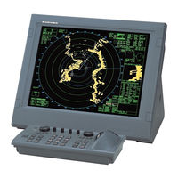
Furuno FCR-2837S Operator's Manual (556 pages)
MARINE RADAR/ARPA
Brand:
Furuno
| Category:
Marine Radar
| Size: 8.13 MB
Table of Contents
Table of Contents
7
Foreword
17
System Configuration
19
1 Operational Overview
23
Units of the System
23
Control Units
23
Chart Processor Unit
25
Turning the Power On/Off
25
Monitor Brilliance
26
Menu Operation
27
Using the Trackball Module
30
The Scrollwheel
30
Calling Menus and Functions by the Mouse Buttons
31
Operation Modes
32
When Chart Radar Mode Can be Used
32
Switching Modes
32
Configuring Hot Keys F1-F4
33
Geodetic Datum
34
Turning EBL, VRM On/Off
34
Ebl
35
Vrm
35
Shifting the Reference Point of EBL and VRM
36
Ship's Position
37
Customizing Operation
38
Alerts Description
39
Charts
40
Route Monitor
40
Switching Hub HUB-100
41
2 Radar Operation
43
Radar Display
43
Radar Mode
43
Chart Radar Mode
44
Tuning the Receiver
45
Choosing the Tuning Method
45
Initializing Tuning
45
Automatic Tuning
45
Manual Tuning
45
Heading with Gyrocompass
46
Presentation Modes
47
Description of Presentation Modes
48
Entering Own Ship's Speed
51
Speed Selection for SPD and SB (TT, AIS and Trails)
51
Speed Selection for COG and SOG (Navigation)
51
Manual Speed Input
53
Choosing the Range Scale
54
Adjusting the Sensitivity
54
Suppressing Sea Clutter
54
Automatic Adjustment by the A/C SEA Control
55
Manual Adjustment of A/C SEA
55
Suppressing Rain Clutter
56
Turning AUTO RAIN on or off
56
Adjusting A/C RAIN
56
Interference Rejector
58
Measuring the Range
58
Turning Range Rings On/Off
58
Measuring Range by the Variable Range Marker (VRM)
59
Measuring the Bearing
60
Choosing True or Relative Bearing
60
Pulse Length
61
Choosing Pulse Length
61
Changing Pulse Length
61
Collision Assessment by Offset EBL
62
Assessing Risk of Collision by the Offset EBL
62
Choosing Point of Reference for Origin Point of Offset EBL
63
Measuring Range and Bearing between Two Targets
64
Off-Centering the Display
65
Echo Stretch
66
Echo Averaging
66
Target Trails
67
True or Relative Trails
67
Trail Time
67
Resetting Target Trails
67
Temporarily Removing Trails
67
Parallel Index (PI) Lines
68
Markers
70
Automatic Picture Setup According to Navigation Purpose
71
Choosing a Picture Setup Option
74
User-Programmable Picture Setups
74
Restoring User Settings
75
Restoring Default Picture Setup Options
75
Noise Rejector
76
Suppressing Second-Trace Echoes
77
Adjusting Brilliance of Screen Data
78
Watch Alarm
79
Interswitch
80
Displaying Antenna Information
80
Presetting Antenna and Display Combinations
81
Selection Considerations
81
Selecting the Antenna
82
Performance Monitor
83
Color and Brilliance Sets
84
Reference Position
85
Cursor Position Data
86
Drop Mark
87
Anchor Watch
88
Chart Display Dialog
89
Chart Database Information
89
2.35.1 Selecting Pre Defined Chart Database Display Settings
90
2.35.2 Creating User-Defined Chart Database Display Settings
90
Temporary Chart Priority Display Control
91
Chart Priority
91
Coast Line Only
91
Chart Status Box
91
Chart Alert Function
92
3 Radar Observation
93
General
93
Minimum and Maximum Ranges
93
False Echoes
95
SART (Search and Rescue Transponder)
96
SART Description
96
Showing SART Marks on the Radar Display
97
General Remarks on Receiving SART
97
Racon
98
Radar Target Enhancer (RTE)
98
4 Target Tracking (TT) Operation
99
Usage Precautions
99
Controls for TT
100
Showing, Hiding TT
100
Entering Own Ship's Speed
101
Echo-Referenced Speed Input
101
Automatic Acquisition
102
Enabling Auto Acquisition
102
Terminating Tracking of Targets (Including Reference Targets)
103
Manual Acquisition
103
Setting Manual Acquisition Conditions
103
Manually Acquiring a Target
104
TT Symbols and TT Symbol Attributes
105
TT Symbols
105
TT Symbol Brilliance
106
Color and Size for Tracked Target Symbol
107
Displaying Tracked Target Data
108
Displaying Target Data for Individual Tracked Target
108
Displaying Individual Tracked Target Data
109
Vector Modes
110
Description of Vectors
110
Vector Motion and Length
111
Past Position Display
112
Displaying and Erasing Past Position Points, Choosing Past Position Plot Interval
112
Past Position Display Attributes
113
Predictor
114
Predictor Settings
114
Set and Drift
115
TT Collision Alarm
116
Setting CPA and TCPA Ranges
116
Setting an Acquisition Zone
117
Activating an Acquisition Zone
117
Sleeping, Deactivating an Acquisition Zone
118
Acknowledging the Acquisition Zone Alarm
118
Acquisition Zone Stabilization
118
TT Alerts
119
Trial Maneuver
120
Types of Trial Maneuvers
120
Performing a Trial Maneuver
121
TT Performance Test
124
Criteria for Selecting Targets for Tracking
125
Factors Affecting TT Functions
126
5 AIS Operation
127
Controls for AIS
128
Turning AIS Function off
129
Turning AIS Display On/Off
129
AIS Symbols
130
Filtering AIS Targets
131
Activating Targets
133
Activating Specific Target
133
Activating All Targets
133
Sleeping Targets
134
Sleeping an Activated AIS Target
134
Sleeping All Activated AIS Targets
134
Displaying Target Data
135
Basic Data
135
Detailed Target Data
136
Setting CPA and TCPA Limits
137
Activating, Deactivating Danger Alarm for Dangerous AIS Targets
137
CPA Auto Activation Setting
138
AIS Symbol Attributes
139
AIS Symbol Brilliance
139
AIS Symbol Color, Outlines, ROT
140
Lost AIS Targets
141
Enabling, Disabling Audio Alarm for Lost Target
141
Displaying AIS Target Past Positions
142
Displaying and Erasing Past Position Points, Choosing Past Position Interval
142
Past Position Display Attributes
143
Displaying True or Relative Speed Vectors
144
Association of TT and AIS Targets
144
Activating Association
144
AIS Own Ship Info
148
AIS Safety Messages
149
Introduction
149
Creating a New Safety Message
150
Reading a Received Safety Message
151
Replying to a Safety Message
152
AIS Alerts
153
6 ECDIS Overview
155
ECDIS Overview
156
User Interface
156
Information Area
157
Sidebar on User Interface
158
Controlling Planning and Monitoring Modes on the ECDIS Display
164
Setting up before Departure
165
Setting Chart Alert Calculation
165
Creating or Updating a Route
166
Checking and Preparing Route to Monitor
167
Verifying Configuration of Navigation Sensors
170
Resetting Distance and Trip Counters
172
Verifying Datum
172
7 Vector Chart Material
173
S57 Charts
173
Introduction
173
Chart Legend for S57 Chart
174
Permanent Messages for S57 Charts
175
Loading S57 Charts
176
Flow Chart for Loading S57 Charts into Chart Radar
176
Loading S57 Charts from a CD ROM, Floppy Disk or LAN
178
Loading S57 Charts Which Are Not Fully Compliant with the IMO Standards
186
S57 SENC Conversion Details
187
Speeding up SENC Conversion
187
Choosing Automatic SENC Conversion and Display until Date
188
Viewing Progress of SENC Conversion
189
Using the Failed SENC Conversion Window
190
Using SENC Conversion History Log
191
Using SENC Convert Window to Initiate SENC Conversion
193
Features of the Chart Menu
194
Overview of the Chart Menu
194
Catalogue of S57 Cells
196
Grouping S57 Chart Cells
198
Viewing Status and Setting Viewing Dates of S57 Chart Cells and Their Updates
206
Removing an S57 Chart Cell from the System
207
S57 Chart Service from an RENC
208
Introduction
208
Permits
208
Product List
208
Authentication
208
Available Service Types
209
Services Provided by an RENC
210
Viewing the Coverage of an RENC Service
210
Knowing Up-To-Date Status of a Chart from an RENC
211
Knowing Up-To-Date Status of an RENC Product List
212
Managing Permits from an RENC
213
Managing Public Key from an RENC
214
CD ROM Service from an RENC
216
Getting Started with S57 Charts Using an RENC
216
Keeping S57 Charts up to Date Using an RENC
217
Enlarging Chart Coverage Using an RENC
218
Base CD ROM from an RENC
218
Viewing Coverage of a Base or Update CD ROM from an RENC
222
Loading an RENC-Generated Permit CD ROM or Floppy Disk
223
RENC Security System
225
Standard Messages in S57 Chart Load
225
Additional Messages in S57 Chart Load
225
Additional Messages in S57 SENC Conversion
227
Vector Chart Display
228
Choosing Charts for Viewing
228
Choosing a Chart by Its Name
229
Controlling Visible Chart Features (Chart Display)
229
Display Base
233
Controlling Visible Navigation Features (Symbol Display)
233
Storing and Recalling Chart Display Setting for Visible Chart and Navigational Features
238
Control of Predefined IMO Chart Display Settings
239
Sailing Directions, Tidal Tables, Etc., Features of Vector Charts
240
Chart Viewing Dates and Seasonal Features of the Vector Chart
241
Introduction
241
Approving and Highlighting Vector Chart Updates
241
Setting "Display Until" Date
242
Setting "Approve Until" Date
242
About Chart Viewing Date Dependency of S57 Standard
243
Symbology Used in Vector Charts
248
How to Change Presentation Library Used for Vector Chart Features
248
Requesting Information about Vector Chart Objects
249
Setting Visible Vector Chart Features
249
Choosing Desired Object from the List of Found Objects
249
Viewing Properties of a Vector Chart Object
251
About Vector Chart Coding
252
Other Features of Vector Charts
258
Cell Status
258
S57 Cell Details
259
Using Cell Status Window to Initiate SENC Conversion
260
8 Manual Updates
261
Symbols to Use with Manual Updates
262
Displaying Manual Updates
262
Controlling Visibility of Orange Symbols from Manual Updates
262
Controlling Visibility of True Symbols from Manual Updates
263
Controlling Chart Viewing Dates of Manual Updates
263
Setting Current Date for Viewing
263
Using Manual Update Editor W/Orange Symbols
264
Manual Update Planning
264
Inserting New Orange Symbols
265
Deleting Orange Symbols
268
Editing Position of Orange Symbols
269
Using Manual Update Editor with True Symbols
272
Manual Update Planning
272
Inserting New Chart Objects
273
Modifying Chart Objects
278
Deleting Chart Objects
280
Editing Properties of Manually Updated Chart Objects
281
Checking Creation and Usage History of Manual Updates
284
9 Chart Alerts
285
Chart Alerts
286
Choosing Safety Contour
286
Choosing Objects Used in Chart Alerts
287
Highlighting Chart Alert Areas
289
Inserting User Chart Symbols, Lines and Areas in Chart Alert
290
Activating Own Ship Check
292
10. Route Planning
300
10 Route Planning
301
Choosing Datum
302
Creating a New Route
303
Processing Waypoints
304
Using the Alerts Page
305
Using the Check Page
306
Using the Parameters Page
307
Using the Prepare Page
308
Modifying an Existing Route
309
Parameters
309
Changing Waypoint Position
309
Changing Other Waypoint Data
311
Adding a New Waypoint at the End of a Route
311
Inserting a Waypoint
312
Deleting a Waypoint
313
Importing Waypoint from Other Routes
313
Importing Waypoint from External Device
314
Reversing Sailing Order of a Route
315
10.4.10 Geometry Check of Route
315
Route Optimization
315
Available Route Optimization Strategies
315
Optimizing a Route
316
Planning a Speed Profile
316
Backup
317
WPT Table Report
317
Full WPT Report
319
Passage Plan Report
320
11 Route Monitoring
323
Choosing Route to Monitor
323
Choosing to Waypoint
324
Choosing Final Waypoint
325
Viewing Waypoint Information
325
Displaying a Route on the Electronic Chart Screen
326
Route Assistant
327
Monitoring a Route
329
ETA (Estimated Time of Arrival)
330
Route Monitoring Alerts
332
12 User Chart Control
333
Introduction
333
Objects of User Charts
333
Modes of User Charts
334
What Is a User Chart Point and How Is It Used
336
Choosing Datum
338
Choosing User Chart to Use in Monitoring Mode
338
Choosing User Chart to Use in Planning Mode
339
Creating a User Chart
340
Point Page
341
Symbol Page
342
Line Page
343
Tidal Page
344
Area Page
345
Importing an Area to a User Chart
347
Adding a New Point, Symbol, Line or Tidal to a User Chart
347
Changing Other Data of Point, Symbol, Line or Tidal
348
Deleting a Point, Symbol, Line or Tidal
348
Importing Points, Symbols, Lines or Tidals from Other User Chart
349
Joining Two or more User Charts
349
Displaying User Charts
350
12.10 Reports
352
13 Notes
353
Introduction
353
Notes Modes
354
Using Notes
355
Selecting Notes to Use in Monitoring Mode
356
Monitor Notes Dialog Box Description
357
Selecting Notes to Use in Planning Mode
358
Plan Notes Dialog Box Description
359
Creating New Notes
360
Adding New Notes Record
360
Choosing Notes Record to Modify
361
Changing Notes Record Position
361
Changing Other Data of Notes Record
361
Deleting a Notes Record
361
Importing Notes from Other Routes
362
14 Backup Operations
363
Introduction
363
File Operations
364
Floppy Disk Operations
364
Vector Format Data
365
ASCII Text File
365
Chart
366
15 Navigation Sensors
369
Choosing Navigation Sensors
369
Sensors Dialog Box Description
369
Source of Position
373
Primary and Secondary Positions of Own Ship
374
Position Discrepancy Alert
374
Source of Navigation Data
375
Kalman Filter
378
Position Alignment
379
Position Alignment by Means of the Chart Radar
379
Resetting Position Alignment
381
Gyro Error Correction
382
Enabling Gyro Error Correction
383
Wind Sensor
384
Installation Parameter for Wind Sensor
385
Depth Sensor
387
15.10 Sensor-Related Alerts
388
16 Recording Functions
389
Events and man Overboard Functions
389
Voyage Records
390
Details Log
390
Voyage Log
391
Danger Target Log
395
Chart Usage Log
397
Printing Details, Voyage or Danger Targets Log
397
Making Backup Copy from Details, Voyage or Danger Target Log
399
Resetting (Emptying) Voyage and Danger Targets Logs
400
Making a User Chart from a Log (Past Track)
400
Alert Log
402
Distance and Trip Counters
403
17 NAVTEX Messages
405
Introduction
405
Receiving NAVTEX Message
405
18 Anchor Watch
407
Introduction
407
Activating Anchor Watch
407
Deactivating Anchor Watch
408
19 Parameters Setup
409
Parameters
409
Parameter-Related Menus
410
Choosing Datum
411
Navigation Parameters Setting
411
Optimization Parameters Setting
412
Color Calibration Settings
413
Color Differentiation Test for S57 Charts
413
Gray Scale Test
414
20 Alerts
417
Introduction
417
Overview
417
Alerts Generated by Navigation Calculation
418
Alerts Generated by Chart Calculation
418
Alerts Generated by Radar
418
Description of the Alert Priority System
419
Warnings for Doubtful Integrity
421
Alert Reporting to Central Alert Management
421
Alert Reception from Connected Sensors
421
20.10 List of Alerts
422
20.10.1 List of Navigation Alerts
422
20.10.2 List of Chart Alerts
431
20.10.3 List of Radar Related Alerts
432
20.10.4 List of External Sensor Related Alerts
438
21 Common Reference System
439
Installation of System
439
Reference Management
439
22 Maintenance and Troubleshooting
441
Maintenance
442
Replacing Parts
443
Troubleshooting
445
Advanced-Level Troubleshooting
447
Keyboard Test
451
Appendix 1: Menu Overview
453
Radar/Chart Radar Menu
453
Ecdis Menu
454
Appendix 2: IHO ECDIS Chart 1
463
Appendix 3: Interpreting S57 Charts
463
Appendix 4: C-MAP CM-93/3 Charts
477
A4.1.1 Registration of the System at C-MAP Norway
477
A4.1.2 Ordering Charts
477
A4.1.3 Applying Licenses
477
A4.1.4 Troubleshooting
477
A4.2 Chart Subscription Service
478
A4.2.1 C-MAP Service
478
A4.2.1 What Is SENC Delivery
478
A4.2.2 CM-ENC Service (SENC Delivery
479
A4.2.3 RENC Service
480
A4.2.4 CM-93/3 Prof, CM-93/3 Prof+ and CM-93/2 Services
481
A4.3 CM93/3 Chart Display
482
A4.3.1 Introduction
482
A4.3.2 Choosing CM93/3 Chart Material to Use
483
A4.3.3 Choosing Charts for Viewing
483
A4.3.4 Chart Catalogue of C-MAP Charts
485
A4.4 S57 Managing C-MAP Charts
486
A4.4.1 Licensing System Used by the C-MAP
486
A4.4.3 System ID for C-MAP
486
A4.5 CM93/3 Database
487
A4.5.1 Load of CM93/3 Database to ECDIS
487
A4.5.2 Use of Multiple Databases
488
A4.6 License of CM93/3
489
A4.6.1 Add License from File
489
A4.6.2 Add License Manually
491
A4.6.3 Renewal of License
492
A4.7 How to Keep Charts up to Date
493
A4.7.1 Creating Update Order File
493
A4.7.2 Loading Chart Updates from the File
495
A4.7.3 Review of Chart Updates
497
A4.7.4 How to View Update Status of CM93/3 Charts
499
A4.7.5 How to View Update History of CM93/3 Charts
500
A4.8 Removing CM93/3 Charts
501
Appendix 5: Digital Interface
503
Digital Interface
503
Input Sentence
503
Output Sentences
503
Data Reception
503
Validity and Integrity of Input Data (Mode Indicator
503
Data Sentences
504
Serial Interface, Radar Processor Unit - Input Ports
524
Serial Interface, Radar Processor Unit- Output Ports
525
Serial Interface, LAN Adapter - Input Ports
525
Serial Interface, LAN Adapter - Output Port
526
Parts Location
533
Advertisement
Advertisement
Related Products
Furuno FCR-2839S-BB
Furuno FCR-2839S
Furuno FCR-2839SW
Furuno FCR-2837SW
Furuno FCR-2807-BB
Furuno FCR-2817
Furuno FCR-2827
Furuno FCR-2829S
Furuno FCR-2829
Furuno FCR-2827W
Furuno Categories
Marine Radar
Marine Equipment
Sonar
Monitor
GPS
More Furuno Manuals
Login
Sign In
OR
Sign in with Facebook
Sign in with Google
Upload manual
Upload from disk
Upload from URL