Sign In
Upload
Manuals
Brands
Delta Manuals
Servo Drives
ASD-B2-1521-F
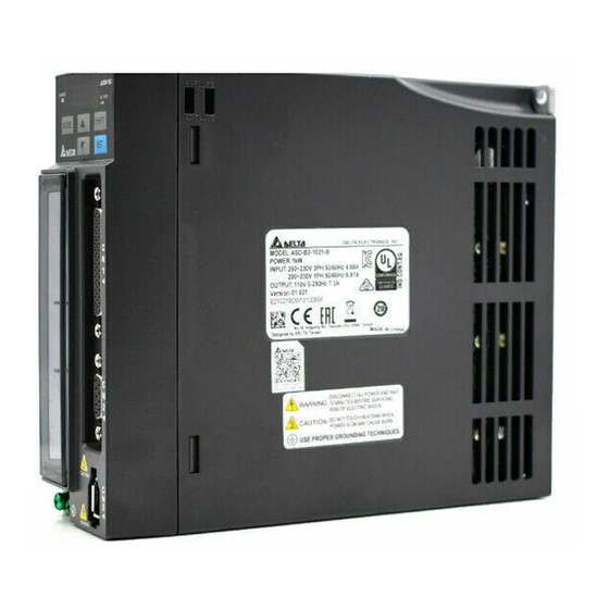
User Manuals: Delta ASD-B2-1521-F AC Servo Drive
Manuals and User Guides for Delta ASD-B2-1521-F AC Servo Drive. We have
2
Delta ASD-B2-1521-F AC Servo Drive manuals available for free PDF download: User Manual
Delta ASD-B2-1521-F User Manual (345 pages)
ASDA-B2 Series
Brand:
Delta
| Category:
Servo Drives
| Size: 14 MB
Table of Contents
Table of Contents
6
Inspection
14
Product Model
15
Nameplate Information
15
Chapter 1 Installation and Model Explanation
15
Model Explanation
16
Servo Drive and Corresponding Servo Motor
18
Servo Drive Features
20
Control Modes of Servo Drive
21
Chapter 2 Installation
22
Notes
22
Ambient Conditions of Storage
22
Ambient Conditions of Installation
23
Installation Direction and Space
24
Troubleshooting for the Motor Operation and Status
26
Servo Motor Mounting Directions and Precautions
26
Precautions for Using Oil Seal Servo Motors
27
Precautions for Using Couplings
28
Oil and Water Prevention Measures for the Servo Motor
29
Measures to Suppress Temperature Increase of the Servo Motor
29
Specification of Circuit Breaker and Fuse
30
EMI Filter Selection
31
Selection of Regenerative Resistor
33
Chapter 3 Wiring
40
Connections
40
Connecting to Peripheral Devices
40
Servo Drive Connectors and Terminals
41
Wiring Method
43
Specification of Motor Power Cable
45
Specification of Encoder Connector
47
Selection of Wiring Rod
51
Basic Wiring
53
Included) and Models below
53
750 W Models
54
Kw ~ 3 Kw Models
55
I / O Signal (CN1) Connection
56
I/O Signal (CN1) Connector Terminal Layout
56
Signals Explanation of Connector CN1
58
Wiring Diagrams (CN1)
66
DI and DO Signal Specified by Users
73
CN2 Connector
74
Wiring of CN3 Connector
76
Analog Monitor Output Connector - CN5
77
Standard Connection Example
78
Position (PT) Control Mode
78
Speed Control Mode
79
Torque Control Mode
80
Chapter 4 Panel Display and Operation
82
Panel Description
82
Parameter Setting Procedure
83
Status Display
84
Save Setting Display
84
Decimal Point
84
Alarm Message
84
Positive and Negative Sign Setting
85
Monitor Display
85
General Function
88
Operation of Fault Code Display
88
JOG Mode
89
Force DO Output
90
Digital Input Diagnosis Operation
91
Digital Output Diagnosis Operation
91
Chapter 5 Trial Operation and Tuning
92
Inspection Without Load
92
Applying Power to the Servo Drive
94
JOG Trial Run Without Load
98
Trial Run Without Load (Speed Mode)
99
Tuning Procedure
101
Flowchart of Tuning Procedure
102
Inertia Estimation Flowchart (with Mechanism)
103
Flowchart of Auto Tuning
104
Flowchart of Semi-Auto Tuning
105
Limit of Inertia Ratio
106
Mechanical Resonance Suppression Method
108
Tuning Modes and Parameters
109
Tuning in Manual Mode
110
Chapter 6 Control Modes of Operation
112
Selection of Operation Mode
112
Position Mode
114
Position Command in PT Mode
114
Control Structure of Position Mode
117
Electronic Gear Ratio
119
Low-Pass Filter
121
Gain Adjustment of Position Loop
122
Speed Mode
125
Selection of Speed Mode
125
Control Structure of Speed Mode
126
Smoothing Speed Command
127
The Scaling of Analog Command
131
Timing Diagram in Speed Mode
132
Gain Adjustment of Speed Loop
132
Resonance Suppression
139
Torque Mode
147
Selection of Torque Command
147
Control Structure of Torque Mode
148
Smooth Torque Mode
149
The Scaling of Analog Command
149
Timing Diagram of Torque Mode
151
Dual Modes
152
Speed / Position Dual Mode
152
Speed / Torque Dual Mode
153
Torque / Position Dual Mode
153
Others
154
The Use of Speed Limit
154
The Use of Torque Limit
154
Analog Monitor
155
The Use of Brake
160
Chapter 7 Parameters
162
Parameter Definition
162
Lists of Parameters
163
Parameter Description
173
P0-XX Monitor Parameters
173
P1-XX Basic Parameters
182
P2-XX Extension Parameters
212
P3-XX Communication Parameters
241
P4-XX Diagnosis Parameters
246
Table 7.1 Function Description of Digital Input (DI)
257
Table 7.3 Monitoring Variables Descriptions
266
Chapter 8 Communications
270
RS-232 Communication Hardware Interface
270
RS-232Communication Parameter Settings
272
MODBUS Communication Protocol
275
Write-In and Read-Out Communication Parameters
287
Chapter 9 Troubleshooting
288
Alarm of Servo Drive
288
Causes and Corrective Actions
291
Corrective Actions after the Alarm Occurs
302
Chapter 10 Specifications
304
Specifications of Servo Drives (ASDA-B2 Series)
304
Specifications of Servo Motors (ECMA Series)
307
Torque Features (T-N Curves)
315
Overload Features
317
Dimensions of Servo Drives
319
Dimensions of Servo Motors
323
Appendix A Accessories
328
Appendix B Maintenance and Inspection
345
Advertisement
Delta ASD-B2-1521-F User Manual (291 pages)
Economic AC Servo Drive with DMCNET Communication
Brand:
Delta
| Category:
Servo Drives
| Size: 3 MB
Table of Contents
Table of Contents
4
Inspection and Model Explanation
10
Inspection
11
Product Model
12
Nameplate Information
12
Model Explanation
13
Inspection and Model Explanation
11
Servo Drive and Corresponding Servo Motor
15
Each Part of the Servo Drive
16
Installation
18
Ambient Conditions of Installation
19
Installation Direction and Space
20
Specification of Circuit Breaker and Fuse
22
EMI Filter Selection
22
Selection of Regenerative Resistor
24
Notes
19
Ambient Conditions of Storage
19
Wiring
30
Connections
31
Connecting to Peripheral Devices
31
Connectors and Terminals of Servo Drive
32
Wiring Method
33
Specification of Motor Power Cable
34
Specification of Encoder Cable Connector
36
Selection of Wiring Rod
39
Basic Wiring
40
Or Models below (Without Built-In Regenerative Resistor nor Fan)
40
750 W Models (with Built-In Regenerative Resistor but no Fan)
41
Kw ~ 1.5 Kw Models (with Built-In Regenerative Resistor and Fan)
42
Kw ~ 3 Kw Models (with Built-In Regenerative Resistor and Fan)
43
I / O Signal (CN1) Connection
44
I / O Signal (CN1) Connector Terminal Layout
44
Signals Explanation of Connector CN1
45
Wiring Diagrams (CN1)
47
DI and DO Signal Specified by Users
49
CN2 Connector
50
Wiring of CN3 Connector
52
CN6 Connector (DMCNET)
53
Standard Connection Example
55
Panel Display and 4
56
Panel Display and Operation
56
Panel Description
57
Parameter Setting Procedure
58
Alarm Message
61
Status Display
61
Save Setting Display
61
Decimal Point
61
Positive and Negative Sign Setting
62
Monitor Display
62
General Function
65
Operation of Fault Record Display
65
JOG Mode
66
Digital Input Diagnosis Operation
68
Digital Output Diagnosis Operation
69
Trial Operation and Tuning
70
Inspection Without Load
71
Apply Power to the Servo Drive
72
JOG Trial Run Without Load
76
Trial Run Without Load (Speed Mode)
77
Tuning Procedure
79
Flowchart of Tuning Procedure
80
Inertia Estimation Flowchart (with Mechanism)
81
Flowchart of Auto Tuning
82
Flowchart of Semi-Auto Tuning
83
Limit of Inertia Ratio
84
Mechanical Resonance Suppression Method
86
Tuning Mode and Parameters
87
Tuning in Manual Mode
88
Control Mode of Operation
90
Selection of Operation Mode
91
Position Mode
92
Control Structure of Position Mode
92
S-Curve Filter (Position)
93
Electronic Gear Ratio
94
Low-Pass Filter
95
Gain Adjustment of Position Loop
95
Low-Frequency Vibration Suppression in Position Mode
96
Selection of Speed Command
99
Speed Mode
99
Control Structure of Speed Mode
100
Smooth Speed Command
101
Timing Diagram of Speed Mode
102
Gain Adjustment of Speed Loop
103
Resonance Suppression
107
Torque Mode
112
Selection of Torque Command
112
Control Structure of Torque Mode
113
Smooth Torque Command
114
Timing Diagram of Torque Mode
114
The Use of Brake
115
Parameter Definition
119
List of Parameters
120
Parameter Description
127
P0-XX Monitor Parameters
127
P1-XX Basic Parameters
139
P2-XX Extension Parameters
154
P3-XX Communication Parameters
167
P4-XX Diagnosis Parameters
172
P5-XX Motion Setting Parameters
176
Communications
186
Communication Hardware Interface
187
Communication Parameters Setting
188
MODBUS Communication Protocol
189
Setting and Accessing Communication Parameters
200
Troubleshooting
202
Alarm of Servo Drive
203
Alarm of DMCNET Communication
204
Alarm of Motion Control
205
Causes and Corrective Actions
206
Absolute System
218
Absolute Type of Battery Box and Wiring Rods
220
Specifications
220
Battery Box Dimensions
222
Connection Cable for Absolute Encoder
223
Battery Box Cable
225
Install Battery Box in Servo System
226
Installation
226
How to Install the Battery
230
How to Replace a Battery
231
Parameters Related to Absolute Servo System
233
Servo Drive Alarm List for Absolute Function and Monitoring Variables
234
System Initialization and Operation Procedures
235
System Initialization
235
Pulse Number
236
PUU Number
237
To Initialize the Absolute Coordinate Via Parameters
238
Use Communication to Access Absolute Position
238
Specifications Appendix
240
Specifications of ASDA-B2-F Servo Drive
241
Specifications of Servo Motors (ECMA Series
243
Torque Features (T-N Curves
252
Overload Features
254
Dimensions of Servo Drive
256
Dimensions of Servo Motor
260
Accessories Appendix
266
Power Connector
267
Power Cable
268
Encoder Cable
270
Encoder Connector
270
Encoder Cable (Absolute Type
271
Battery Box Cable AW
272
Battery Box Cable IW
272
Battery Box (Absolute Type
273
CN1 Convenient Connector
274
I / O Connector Terminal
274
PC Connection Cable
275
Terminal Block Module
275
Optional Accessories
276
Advertisement
Related Products
Delta ASD-B2-1021-F
Delta ASD-B2-1021 Series
Delta ASD-B2-1521 Series
Delta ASD-B2-0121-F
Delta ASD-B2-0221-F
Delta ASD-B2-0721-F
Delta ASD-B2-0221 Series
Delta ASD-B2-0721 Series
Delta ASD-B2-3023 Series
Delta ASD-B2-2023 Series
Delta Categories
Plumbing Product
Kitchen & Bath Fixtures
Bathroom Fixtures
Saw
Power Supply
More Delta Manuals
Login
Sign In
OR
Sign in with Facebook
Sign in with Google
Upload manual
Upload from disk
Upload from URL