Table of Contents
Advertisement
Quick Links
Advertisement
Table of Contents
Troubleshooting

Related Manuals for Delta ASD-B2-1521-F


Summary of Contents for Delta ASD-B2-1521-F
- Page 1 DELTA_IA-ASDA_B2_UM_EN_20180509...
- Page 2 Preface Thank you for purchasing ASDA-B2. This user manual provides the related information of ECMA series servo motors. This manual includes: Installation and inspection of servo drive and servo motor The configuration of servo drive Procedures of trial run Control functions and adjustment methods of servo drives Parameter Communication protocol Inspection and maintenance...
- Page 3 Do not touch the heat sink to avoid scald before connecting to the power and operation. If you have any enquiry, please contact the distributors or Delta customer service center. Safety Precautions ASDA-B2 series is the high resolution and open type servo drive. It should be installed in a shielded control box during operation.
- Page 4 ASDA-B2 Preface Wiring Please connect the ground terminal to class-3 ground system (under 100 Ω); poor grounding may result in electric shock or fire. Do not connect the three-phase source to the motor output terminal U, V and W. Or it is possible to cause personnel injury or fire. Please tighten the screws of the power and motor output terminal.
- Page 5 When inserting the electric wires, do not connect the conductor to the adjacent wire. Before connecting to the power, please inspect and be ensured the wiring is correct. If there is any difference of each version, please refer to DELTA’s NOTE website (http://www.delta.com.tw/industrialautomation/) for the latest information.
-
Page 6: Table Of Contents
Table of Contents Chapter 1 Installation and Model Explanation ............1-1 1.1 Inspection ......................1-1 1.2 Product Model ....................1-2 1.2.1 Nameplate Information ................1-2 1.2.2 Model Explanation .................. 1-3 1.3 Servo Drive and Corresponding Servo Motor ..........1-5 1.4 Servo Drive Features ..................1-7 1.5 Control Modes of Servo Drive ................. - Page 7 Table of Contents ASDA-B2 2.6 EMI Filter Selection ..................2-10 2.7 Selection of Regenerative Resistor ..............2-12 Chapter 3 Wiring ...................... 3-1 3.1 Connections ....................3-1 3.1.1 Connecting to Peripheral Devices ............3-1 3.1.2 Servo Drive Connectors and Terminals ..........3-2 3.1.3 Wiring Method ..................
- Page 8 ASDA-B2 Table of Contents 3.7 Standard Connection Example ................ 3-39 3.7.1 Position (PT) Control Mode ..............3-39 3.7.2 Speed Control Mode ................3-40 3.7.3 Torque Control Mode ................3-41 Chapter 4 Panel Display and Operation ..............4-1 4.1 Panel Description .................... 4-1 4.2 Parameter Setting Procedure ................
- Page 9 Table of Contents ASDA-B2 5.4 Trial Run without Load (Speed Mode) ............. 5-8 5.5 Tuning Procedure .................... 5-10 5.5.1 Flowchart of Tuning Procedure .............. 5-11 5.5.2 Inertia Estimation Flowchart (with Mechanism) ........5-12 5.5.3 Flowchart of Auto Tuning................ 5-13 5.5.4 Flowchart of Semi-Auto Tuning .............. 5-14 5.5.5 Limit of Inertia Ratio ................
- Page 10 ASDA-B2 Table of Contents 6.3.5 Timing Diagram in Speed Mode ............. 6-21 6.3.6 Gain Adjustment of Speed Loop ............. 6-21 6.3.7 Resonance Suppression ................ 6-28 6.4 Torque Mode ....................6-36 6.4.1 Selection of Torque Command ............... 6-36 6.4.2 Control Structure of Torque Mode ............6-37 6.4.3 Smooth Torque Mode ................
- Page 11 Table of Contents ASDA-B2 P1-xx Basic Parameters .................. 7-21 P2-xx Extension Parameters ................7-51 P3-xx Communication Parameters ..............7-80 P4-xx Diagnosis Parameters ................7-85 Table 7.1 Function Description of Digital Input (DI) ......... 7-96 Table 7.2 Function Description of Digital Input Output (DO) ......7-102 Table 7.3 Monitoring Variables Descriptions ...........
- Page 12 ASDA-B2 Table of Contents Appendix A Accessories ..................A-1 Appendix B Maintenance and Inspection .............. B-1 Revision May, 2018...
- Page 13 Due to constantly growing product range, technical improvement, alteration or changed texts, figures and diagrams, we reserve the right to make information changes within this manual without prior notice. Coping or reproducing any part of this manual, without written consent of Delta Electronics Inc. is prohibited. Technical Support and Service Welcome to contact us or visit our web site (http://www.delta.com.tw/ia/) if you need any...
-
Page 14: Inspection
Chapter 1 Installation and Model Explanation 1.1 Inspection In order to prevent the negligence during purchasing and delivery, please inspect the following items carefully. Item Content Please check if the Check the part number of the motor and the servo drive on product is what you have the nameplate. -
Page 15: Product Model
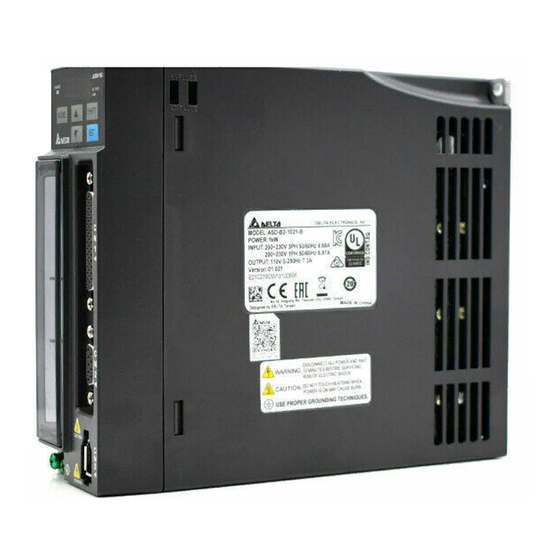
Chapter 1 Installation and Model Explanation ASDA-B2 1.2 Product Model 1.2.1 Nameplate Information ASDA-B2 Series Servo Drive Nameplate Information Serial Number ECMA Series Servo Motor Nameplate Information Serial Number Revision May, 2018... -
Page 16: Model Explanation
ASDA-B2 Chapter 1 Installation and Model Explanation 1.2.2 Model Explanation ASDA-B2 Series Servo Drive A S D - B 2 - 0 4 2 1 - □ Model Type Input Voltage and Phase 21: 220V 1 phase 23: 220V 3 phase Rated Power Input 01: 100W 20: 2kW... - Page 17 Chapter 1 Installation and Model Explanation ASDA-B2 ECMA Series Servo Motor E C M A - C 1 0 6 0 2 E S Standard Shaft Diameter: S Specific Shaft Diameter: 3=42mm, 7=14mm with Type of Shaft With Brake Brake Brake Diameter Brake...
-
Page 18: Servo Drive And Corresponding Servo Motor
ASDA-B2 Chapter 1 Installation and Model Explanation 1.3 Servo Drive and Corresponding Servo Motor Motor Servo Drive Max. Max. Continuous Rated Instantaneou Motor Output Instantaneous Output Power Model Number Current Model Number s output current Current series (Arms) current (Arms) 100 ECMA-C△0401□S 0.90 ASD-B2-0121-□... - Page 19 Chapter 1 Installation and Model Explanation ASDA-B2 The boxes () at the ends of the servo drive model names are the NOTE mode code of ASDA-B2. Please refer to the ordering information of the actual purchased product. The boxes ( ) in the model names are for encoder resolution types. = 1: Incremental type, 20-bit;...
-
Page 20: Servo Drive Features
ASDA-B2 Chapter 1 Installation and Model Explanation 1.4 Servo Drive Features Revision May, 2018... -
Page 21: Control Modes Of Servo Drive
Chapter 1 Installation and Model Explanation ASDA-B2 1.5 Control Modes of Servo Drive Various operation modes are provided. Please refer to the following table: Mode Code Description Servo drive receives the position command and Position Mode commands the servo motor to the target position. The position command is sent from CN1 and its (Terminal Input) signal type is pulse. -
Page 22: Chapter 2 Installation
Chapter 2 Installation 2.1 Notes Please pay close attention to the followings: Do not strain the cables between the servo drive and servo motor. Make sure to each screw is tightened when fixing the servo drive. The motor shaft and the ball screw should be parallel. ... -
Page 23: Ambient Conditions Of Installation
Chapter 2 Installation ASDA-B2 2.3 Ambient Conditions of Installation Operating Temperature ASDA-B2 Series Servo Drive: 0°C to 55°C (32°F to 131°F) ECMA Series Servo Motor : 0°C to 40°C (32°F to 104°F) The ambient temperature of servo drive should be under 45°C (113°F) for long-term reliability. -
Page 24: Installation Direction And Space
ASDA-B2 Chapter 2 Installation 2.4 Installation Direction and Space Notes: Incorrect installation may result in a drive malfunction or premature failure of the drive and or motor. The ASDA-B2 servo drive should be mounted perpendicular to the wall or in the control panel. - Page 25 Chapter 2 Installation ASDA-B2 Scheme of Installation In order to have smaller wind resistance of the fan and increase the ventilation, please follow the suggested clearance value when installing one or more than one servo drives. (Refer to the following diagrams) The above diagrams are not in equal proportion.
-
Page 26: Troubleshooting For The Motor Operation And Status
ASDA-B2 Chapter 2 Installation 2.4.1 Troubleshooting for the Motor Operation and Status Servo motor makes abnormal noise: Possible causes Checking methods Handling measures Check if there is foreign object, Replace the connecting There is a source of damage, or deformation in the component (such as the vibration in the movable parts of the connecting... -
Page 27: Precautions For Using Oil Seal Servo Motors
Chapter 2 Installation ASDA-B2 Installation direction Precautions Vertical - Shaft end up Do not use servo motors with oil seals in the vertical direction. When wiring, you need to install an oil trap to prevent vapor from entering the motor. ... -
Page 28: Precautions For Using Couplings
ASDA-B2 Chapter 2 Installation 2.4.4 Precautions for Using Couplings Caution: It is suggested to use a flexible coupling specifically designed for servo motors, especially double spring couplings, which provide some buffer tolerance during eccentric motion and deflection. Please select appropriate coupling size for the operating conditions. Improper usage or connection may result in damage. -
Page 29: Oil And Water Prevention Measures For The Servo Motor
Do not submerge the cable in oil or water. If oil or water is unavoidable, please use oil-resistant cables. Delta does not provide oil-resistant cables. If the servo motor must be mounted with the shaft end up, do not use it in a machine, gearbox, or other environment where the servo motor may have contact with oil or water. -
Page 30: Specification Of Circuit Breaker And Fuse
ASDA-B2 Chapter 2 Installation (2) Reduce the acceleration and deceleration of the work cycle to lower the motor load. (3) Apply external forced air cooling to the servo motor using cooling fans or other means. Note: do not place a gasket or other insulating materials between the servo motor and heat sink, as this may result in motor temperature increase, noise resistance being affected, and motor malfunction. -
Page 31: Emi Filter Selection
With EMI Filter and the correct installation, much interference can be eliminated. It is suggested to use Delta’s EMI Filter to suppress the interference better. When installing servo drive and EMI Filter, please follow the instructions of the user manual and make sure it meets the following specification. - Page 32 ASDA-B2 Chapter 2 Installation Motor Cable Selection and Installation Precautions The selection of motor cables and installation affect the performance of EMI Filter. Please follow the precautions mention below. 1. Use the cable that has braid shielding (The effect of double shielding is better) 2.
-
Page 33: Selection Of Regenerative Resistor
Chapter 2 Installation ASDA-B2 2.7 Selection of Regenerative Resistor When the direction of pull-out torque is different from the rotation, it means the electricity is sent back to the servo drive from the load-end. It becomes the capacitance of DC Bus and increases the voltage. - Page 34 ASDA-B2 Chapter 2 Installation resistor which is equipped with thermal switches. Please contact the distributors for load characteristics of the regenerative resistor. When using the external regenerative resistor, the resistor should connect to P, C terminal and the contact of P, D terminal should be opened. It is recommended to choose the above mentioned capacitance.
- Page 35 Chapter 2 Installation ASDA-B2 Regenerative Max. power from empty regenerative Rotor Inertia Servo Drive Servo Motor load 3000r/min to power of (kW) J (× 10 kg.m stop capacitance Eo (joule) Ec(joule) ECMA-E△1830 54.95 217.73 ECMA-F△1830 54.95 217.73 ECMA-E△1835 54.95 217.73 1.0 ECMA-F△1308...
- Page 36 ASDA-B2 Chapter 2 Installation resistor will do. Generally speaking, when the need of the external load inertia is not much, the built-in regenerative is enough. The diagram below describes the actual operation. The smaller power of the regenerative resistor it is, the more energy it accumulates and the higher temperature it will be.
- Page 37 Chapter 2 Installation ASDA-B2 Simple Selection Choose the appropriate regenerative resistor according to the allowable frequency and empty load frequency in actual operation. The so-called empty allowable frequency is the frequency of continuous operation when the servo motor runs from 0 r/min to the rated speed and then decelerates from the rated speed to 0 r/min within the shortest time.
- Page 38 Dimensions of Regenerative Resistor Delta Part Number: BR400W040 (400 W 40 Ω) MAX. WEIGHT(g) 2-17 Revision May, 2018...
- Page 39 Chapter 2 Installation ASDA-B2 Delta Part Number: BR1K0W020 (1 kW 20 Ω) MAX. WEIGHT(g) 2800 Regarding the selection of regenerative resistor, please refer to the NOTE table of regenerative resistor specifications described in Appendix A. 2-18 Revision May, 2018...
-
Page 40: Chapter 3 Wiring
Chapter 3 Wiring This chapter provides information on wiring ASDA-B2 series products, the descriptions of I/O signals and gives typical examples of wiring diagrams. 3.1 Connections 3.1.1 Connecting to Peripheral Devices Revision May, 2018... -
Page 41: Servo Drive Connectors And Terminals
Chapter 3 Wiring ASDA-B2 Installation notes: NOTE 1. Check if the power and wiring among R, S, T and L1c, L2c are correct. 2. Please check if the output terminal U, V, W of the servo motor is correctly wired. The incorrect wiring may disable the operation of the motor or cause malfunction. - Page 42 ASDA-B2 Chapter 3 Wiring Terminal Name Description Signal Used to connect grounding wire of power supply and Ground terminal servo motor. places Used to connect external controllers. Please refer to I/O connector section 3.3 for details. Encoder Used to connect encoder of servo motor. Please refer to connector section 3.4 for details.
-
Page 43: Wiring Method
Chapter 3 Wiring ASDA-B2 3.1.3 Wiring Method The wiring method is divided into single-phase and three-phase. Single-phase is for 1.5 kW and the model below 1.5 kW. In the diagram below, Power On is contact a, Power Off and ALRM_RY are contact b. MC is the coil of magnetic contactor and self-remaining power and is the contact of main power circuit. - Page 44 ASDA-B2 Chapter 3 Wiring Wiring Method of Three-phase Power Supply (suitable for all series) Revision May, 2018...
-
Page 45: Specification Of Motor Power Cable
Chapter 3 Wiring ASDA-B2 3.1.4 Specification of Motor Power Cable Terminal Motor Model U, V, W / Connector of Brake Identification ECMA-C△0401S (100W) ECMA-C△0602S (200W) ECMA-C△0604S (400W) ECMA-C△0604H (400W) ECMA-CM0604PS (400W) ECMA-C△08047 (400W) ECMA-C△0807S (750W) ECMA-C △ 0807H (750W) HOUSING: JOWLE (C4201H00-2*2PA) ECMA-CM0807PS (750W) ECMA-C△0907S (750W) ECMA-C△0910S (1000W) - Page 46 ASDA-B2 Chapter 3 Wiring Terminal Motor Model U, V, W / Connector of Brake Identification ECMA-E△1820S (2000W) ECMA-E△1830S (3000W) ECMA-F△1830S (3000W) ECMA-E△1835S (3500W) 3106A-24-11S CASE BRAKE1 BRAKE2 Terminal GROUND Identification (Red) (White) (Black) (Brown) (Blue) (Yellow green) When selecting the wire rod, please choose 600V PVC cable and the length should not longer than 30m.
-
Page 47: Specification Of Encoder Connector
Chapter 3 Wiring ASDA-B2 3.1.5 Specification of Encoder Cable Connector Encoder Connection (Diagram 1) This diagram shows the connection between the servo drive and the NOTE motor encoder. It is not drawn by the practical scale and specification will be different according to the selected servo drive and motor model. Please refer to the Section of Specification and Definition of Encoder Connector. - Page 48 ASDA-B2 Chapter 3 Wiring Terminal Identification of Encoder Connector Connector of Connector of Encoder Cable Motor Encoder Housing : AMP(1-172161-9) Motor Servo Drive Encoder View from this side View from this side (Encoder type is 17bit , 20bit): Blue Reserved Reserved White Reserved...
- Page 49 Chapter 3 Wiring ASDA-B2 Encoder Connection (Diagram 2) This diagram shows the connection between the servo drive and the NOTE motor encoder. It is not drawn by the practical scale and specification will be different according to the selected servo drive and motor model. Please refer to section 3.4 CN2 Connector.
- Page 50 ASDA-B2 Chapter 3 Wiring Motor Model Connector of Encoder Cable ECMA-G△1303S (300W) ECMA-E△1305S (500W) ECMA-G△1306S (600W) ECMA-GM1306PS (600W) ECMA-F△1308S (850W) Terminal Color Identification ECMA-G△1309S (900W) Blue ECMA-GM1309PS (900W) ECMA-C△1010S (1000W) Blue& Black ECMA-E△1310S (1000W) Red/ ECMA-F△1313S (1300W) DC+5V Red & ECMA-E△1315S (1500W) White Black/...
-
Page 51: Selection Of Wiring Rod
Chapter 3 Wiring ASDA-B2 3.1.6 Selection of Wiring Rod The recommended wire rods are shown as the following table: Power Wiring – Wire Diameter mm² (AWG) Servo Drive and corresponding Servo Motor L1c, L2c R, S, T U, V, W P , C ECMA-C△0401S ASD-B2-0121-... - Page 52 ASDA-B2 Chapter 3 Wiring Encoder Wiring - Wire Diameter mm (AWG) Servo Drive Model Size Number Specification Standard Length ASD-B2-0121- ASD-B2-0221- ASD-B2-0421- ASD-B2-0721- 0.13 (AWG26) 10 core (4 pair) UL2464 3m (9.84ft.) ASD-B2-1021- ASD-B2-1521- ASD-B2-2023- ASD-B2-3023- 1. Please use shielded twisted-pair cable for encoder wiring so as to NOTE reduce the interference of the noise.
-
Page 53: Basic Wiring
Chapter 3 Wiring ASDA-B2 3.2 Basic Wiring 3.2.1 200 W (included) and Models Below (without built-in regenerative resistor and cooling fan) 3-14 Revision May, 2018... -
Page 54: 750 W Models
ASDA-B2 Chapter 3 Wiring 3.2.2 400 W ~ 750 W Models (with built-in regenerative resistor, but without cooling fan) 3-15 Revision May, 2018... -
Page 55: Kw ~ 3 Kw Models
Chapter 3 Wiring ASDA-B2 3.2.3 1 kW ~ 3 kW Models (with built-in regenerative resistor and cooling fan) 3-16 Revision May, 2018... -
Page 56: I / O Signal (Cn1) Connection
ASDA-B2 Chapter 3 Wiring 3.3 I / O Signal (CN1) Connection 3.3.1 I/O Signal (CN1) Connector Terminal Layout In order to have a more flexible communication with the master, 6 programmable Digital Outputs (DO) and 9 programmable Digital Inputs (DI) are provided. The setting of 9 digital inputs and 6 digital outputs of each axis provided by ASDA-B2, which are parameter P2- 10~P2-17, P2-36 and parameter P2-18~P2-22, P2-37 respectively. - Page 57 Chapter 3 Wiring ASDA-B2 DO6+ Digital output DO4+ Digital output DI7- Digital input +24V power output (for external I/O) DO3- Digital output DI6- Digital input Analog torque T_REF Input DO3+ Digital output DI5- Digital input Analog input signal ground DO2- Digital output DI3- Digital input...
-
Page 58: Signals Explanation Of Connector Cn1
ASDA-B2 Chapter 3 Wiring 3.3.2 Signals Explanation of Connector CN1 The following details the signals listed in previous section: General Signals Wiring Diagram Signal Pin No Function (Refer to 3.3.3) (1) The speed command of the motor is - 10 V ~ +10 V which means the speed command is -3000 ~ +3000 r/min (default). - Page 59 Chapter 3 Wiring ASDA-B2 Wiring Diagram Signal Pin No Function (Refer to 3.3.3) VDD is the +24 V power provided by the drive and is for Digital Input (DI) and Digital Output (DO) signal. The maximum current is 500 mA. COM+ is the common input of Digital Input (DI) and Digital Output (DO) voltage.
- Page 60 ASDA-B2 Chapter 3 Wiring Users have to select the operation mode based on the needs first (please refer to Chapter 6.1 for the introduction of each mode) and refer to the following DI/DO table to know the corresponding default setting of DI/DO signal and Pin No of the selected mode in order to conduct the wiring.
- Page 61 Chapter 3 Wiring ASDA-B2 1. For example, if the user selects S mode, pin 3 and 2 are TSPD. NOTE 2. The unlisted Pin No means the signal is not the preset one. If users want to use it, parameters need to be changed and set as the desired ones.
- Page 62 ASDA-B2 Chapter 3 Wiring Wiring Method Operatio Function n Mode Signal (Refer to 3.3.3) TCM1 TCM0 Command source T mode: analog input Tz mode: 0 TCM1 P1-12 P1-13 P1-14 Mode switching. OFF: Speed; ON: Position PT-S Mode switching. OFF: Speed; ON: Torque PT-T Mode switching.
- Page 63 Chapter 3 Wiring ASDA-B2 Table 3.1 Default Value of DI Function Symbol Function PT-S PT-T S-T Code 0x01 Servo On ARST 0x02 Alarm Reset GAINUP 0x03 Gain switching CCLR 0x04 Pulse clear ZCLAMP 0x05 Zero speed CLAMP The input command CMDINV 0x06 will be in reverse...
- Page 64 ASDA-B2 Chapter 3 Wiring Symbol Function PT-S PT-T S-T Code Reverse operation TLLM 0x25 torque limit Forward operation TRLM 0x26 torque limit Reserved 0x27 Reserved Reserved 0x36 Reserved JOGU 0x37 Forward JOG input JOGD 0x38 Reverse JOG input Electronic gear ratio GNUM0 0x43 (Numerator) selection...
- Page 65 Chapter 3 Wiring ASDA-B2 Table 3.2 Default Value of DO Function Signal Function PT-S PT-T S-T Code SRDY 0x01 Servo ready DO1 DO1 DO1 DO1 DO1 DO1 DO1 DO1 0x02 Servo On Zero-speed ZSPD 0x03 DO2 DO2 DO2 DO2 DO2 DO2 DO2 DO2 reached Reach the target TSPD...
-
Page 66: Wiring Diagrams (Cn1)
ASDA-B2 Chapter 3 Wiring 3.3.3 Wiring Diagrams (CN1) The valid voltage range of analog input command in speed and torque mode is -10V ~+10V. The command value can be set via relevant parameters. C1: Speed / Torque analog signal input C2: Analog monitor output (MON1, MON2) 3-27 Revision May, 2018... - Page 67 Chapter 3 Wiring ASDA-B2 Pulse command can be input by the way of open-collector or Line driver. The maximum input pulse of Line driver is 500 kpps and 200 kpps for open-collector. C3-1: The source of pulse input is open-collector NPN equipment which applies the internal power of the servo drive.
- Page 68 ASDA-B2 Chapter 3 Wiring C3-3: The source of pulse input is open-collector NPN equipment which applies the external power of the servo drive. C3-4: The source of pulse input is open-collector PNP equipment which applies the external power of the servo drive. ...
- Page 69 Chapter 3 Wiring ASDA-B2 C4-1: Pulse input (Line driver) can only apply to 5V power. Never apply to 24V power. C4-2: High-speed pulse input (Line driver) can only apply to 5V power. Never apply to 24V power. 3-30 Revision May, 2018...
- Page 70 ASDA-B2 Chapter 3 Wiring The high-speed pulse input interface of the servo drive is not the isolated interface. In order to reduce the interference of the noise, it is suggested that the terminal ground of the controller and the servo drive should be connected to each other.
- Page 71 Chapter 3 Wiring ASDA-B2 The DI wiring inputs signal via the relay or open-collector transistor. Conditions of DI On / Off: ON: 15V - 24V; the input current is higher than 3 mA. OFF: below 5V; the input current must not be higher than 0.5 mA. NPN transistor, common emitter (E) mode (SINK mode) C9: Wiring of DI signal The servo drive applies to...
- Page 72 ASDA-B2 Chapter 3 Wiring C13: Encoder signal output (Line driver) C14: Encoder signal output (Opto-isolator) C15: Encoder OCZ output (Open-collector Z-pulse output) 3-33 Revision May, 2018...
-
Page 73: Di And Do Signal Specified By Users
Chapter 3 Wiring ASDA-B2 3.3.4 DI and DO Signal Specified by Users If the default setting of DI/DO signal cannot satisfy the need, self-set the DI/DO signal will do and easy. The signal function of DI1 ~ 9 and DO1 ~ 6 is determined by parameter P2-10 ~ P2-17, P2-36 and parameter P2-18 ~ P2-22, P2-37 respectively. -
Page 74: Cn2 Connector
ASDA-B2 Chapter 3 Wiring 3.4 CN2 Connector There are two types of CN2 encoder cable which shown as below: Encoder CN2 Connector Connector CN2 on drive Connect to the servo Connect to the side drive motor Quick Connector Military Connector Definition of two sides: Encoder Connector 6 7 8 9... - Page 75 Chapter 3 Wiring ASDA-B2 The definition of each signal is as follows: Drive Connector Encoder Connector Terminal Military Quick PIN No. Description Color Symbol Connector Connector Serial communication Blue signal input / output (+) Serial communication Blue & signal input / output (-) Black Red / Red +5V power supply...
-
Page 76: Wiring Of Cn3 Connector
ASDA-B2 Chapter 3 Wiring 3.5 Wiring of CN3 Connector Layout of CN3 Connector The servo drive connects to the personal computer via communication connector. The user can operate the servo drive via MODBUS, PLC or HMI. There are two common communication interfaces, RS-232 and RS-485. -
Page 77: Analog Monitor Output Connector - Cn5
Chapter 3 Wiring ASDA-B2 3.6 Analog Monitor Output Connector - CN5 Analog Monitor Output Connector CN5 is used to monitor the motor operation status. Motor characteristics such as speed and current can be represented by analog voltages. The drive provides two channels which can be configured with the parameter P0-03 to output the desired characteristics. -
Page 78: Standard Connection Example
ASDA-B2 Chapter 3 Wiring 3.7 Standard Connection Example 3.7.1 Position (PT) Control Mode Please note: *1. Please refer to C3 ~ C4 wiring diagrams in section 3.3.3. *2. Please refer to C3 ~ C4 wiring diagrams in section 3.3.3. *3. Please refer to C9 ~ C12 wiring diagrams (SINK / SOURCE mode) in section 3.3.3. -
Page 79: Speed Control Mode
Chapter 3 Wiring ASDA-B2 3.7.2 Speed Control Mode Servo Drive MCCB ASDA-B2 series *2 AC 200/230 V ⊕ Three-phase Regenerative 50/60Hz resistor Power supply White Black 10KΩ EMGS BRKR Brake Green *3 V_REF /SIGN ± 10KΩ 10KΩ Encoder SIGN 10KΩ Blue Blue&... -
Page 80: Torque Control Mode
ASDA-B2 Chapter 3 Wiring 3.7.3 Torque Control Mode Please note: *1. Please refer to C9 ~ C12 wiring diagrams (SINK / SOURCE mode) in section 3.3.3. *2. The servo drive provides built-in regenerative resistor. *3. The brake coil has no polarity. 3-41 Revision May, 2018... - Page 81 Chapter 3 Wiring ASDA-B2 (This page is intentionally left blank.) 3-42 Revision May, 2018...
-
Page 82: Chapter 4 Panel Display And Operation
Chapter 4 Panel Display and Operation This chapter details the panel status and operation of ADSA-B2 series servo drive. 4.1 Panel Description Name Function Five-/Seven-segment display is for displaying the monitoring values, Display parameter values and setting values. Charge LED The Charge LED lights to indicate the power is applied to the circuit. -
Page 83: Parameter Setting Procedure
Chapter 4 Panel Display and Operation ASDA-B2 4.2 Parameter Setting Procedure (1) When the servo drive connects to the power, the display will show the monitor variable for about one second, and then enter into the Monitor Mode. (2) Press the MODE Key can switch mode from Parameter Mode → Monitor Mode → Alarm Mode. -
Page 84: Status Display
ASDA-B2 Chapter 4 Panel Display and Operation 4.3 Status Display 4.3.1 Save Setting Display When finishing editing parameter, press the SET Key to save the setting. The panel will display the setting status according to the setting for a second. Display Symbol Description The setting value is saved correctly. -
Page 85: Positive And Negative Sign Setting
Chapter 4 Panel Display and Operation ASDA-B2 4.3.4 Positive and Negative Sign Setting Display Symbol Description When entering into the Editing Setting Mode, pressing UP / DOWN Key can increase or decrease the displayed content. The SHIFT Key can change the desired adjusted carry value. (The carry value is blinking at the moment.) Pressing the SHIFT Key for two seconds can switch the positive (+) and negative (-) sign. - Page 86 ASDA-B2 Chapter 4 Panel Display and Operation P0-02 Monitor Displayed Description Unit Setting Symbol Torque input command [Volt] Torque input command Average load Peak load Main circuit voltage [Volt] Load / Motor Inertia Ratio [0.1times] (Please note that if the display is 130, it indicates that the actual inertia is 13.0) IGBT temperature Resonance frequency (Low byte is the...
- Page 87 Chapter 4 Panel Display and Operation ASDA-B2 1. Dec means it is displayed in decimal format. Hex means it is NOTE displayed in hexadecimal format. 2. The above display methods can be applied in Monitor Mode and Editing Setting Mode. 3.
-
Page 88: General Function
ASDA-B2 Chapter 4 Panel Display and Operation 4.4 General Function 4.4.1 Operation of Fault Cord Display When it is in Parameter Mode, select P4-00~P4-04 and press the SET Key, the corresponding fault record will be shown. Revision May, 2018... -
Page 89: Jog Mode
Chapter 4 Panel Display and Operation ASDA-B2 4.4.2 JOG Mode When it is in Parameter Mode, select P4-05 and follow the setting method below for JOG operation. (1) Press the SET Key to display the speed value of JOG. The default value is 20 r/min. (2) Press UP or DOWN Key to adjust the desired speed value of JOG. -
Page 90: Force Do Output
ASDA-B2 Chapter 4 Panel Display and Operation 4.4.3 Force DO Output Enter into the Output Diagnosis Mode by the following settings. Set P2-08 to 406 and enable the function of force DO output. Then, set the force DO output by binary method via P4-06. -
Page 91: Digital Input Diagnosis Operation
Chapter 4 Panel Display and Operation ASDA-B2 4.4.4 Digital Input Diagnosis Operation Enter into the Digital Input Diagnosis Mode by the following setting methods. When the external output signal DI1 ~ DI9 is ON, the corresponding signal will be shown on the panel. -
Page 92: Chapter 5 Trial Operation And Tuning
Chapter 5 Trial Operation and Tuning This chapter is divided into two parts to describe the trial operation. The first one is the inspection without load and another one is the inspection with load. For safety reasons, please conduct the first inspection. 5.1 Inspection without Load Please remove the load of the servo motor, including coupling on the shaft and accessories so as to avoid any damage on servo drive or mechanism. - Page 93 The encoder cable should avoid excessive stress. When the motor is running, make sure the cable is not frayed or over extended. Please contact with Delta if there is any vibration of the servo motor or unusual noise during the operation. Inspection before ...
-
Page 94: Applying Power To The Servo Drive
ASDA-B2 Chapter 5 Trial Operation and Tuning 5.2 Applying Power to the Servo Drive Please follow the instructions below. A. Make sure the wiring between the motor and servo drive is correct. (1) U, V, W and FG have to connect to cable red, white, black and green respectively. If the wiring is incorrect, the motor cannot work normally. - Page 95 Chapter 5 Trial Operation and Tuning ASDA-B2 Warning of overvoltage: It means the voltage input by the main circuit is higher than the rated voltage or power input error (incorrect power system). Corrective actions: Use the voltmeter to measure if the input voltage from the main circuit is within the range of rated voltage value.
- Page 96 ASDA-B2 Chapter 5 Trial Operation and Tuning (4) When the screen displays: Warning of negative limit error: Please check if any of the digital input DI1 ~ DI9 is set to negative limit (NL) and that DI is ON. Corrective actions: ...
- Page 97 Chapter 5 Trial Operation and Tuning ASDA-B2 (7) When the screen displays: Warning of under voltage: Corrective actions: Check if the wiring of main circuit input voltage is correct. Use voltmeter to measure if the main circuit voltage is normal. ...
-
Page 98: Jog Trial Run Without Load
ASDA-B2 Chapter 5 Trial Operation and Tuning 5.3 JOG Trial Run without Load It is very convenient to test the motor and servo drive with the method of JOG trial run without load since the extra wiring is unnecessary. For safety reasons, it is recommended to set JOG at low speed. -
Page 99: Trial Run Without Load (Speed Mode)
(DI8). Thus, the value of parameter P2-15 ~ P2-17 and P2-36 is set to 0 (Disabled). The digital input of Delta’s servo drive can be programmed by users. When programming digital input, please refer to the description of DI code. - Page 100 ASDA-B2 Chapter 5 Trial Operation and Tuning The speed command selection is determined by SPD0 and SPD1. See the table below. DI signal of CN1 Speed Command Source Content Range Command No. SPD1 SPD0 External analog Voltage between -10V ~ +10V command V-REF and GND P1-09...
-
Page 101: Tuning Procedure
Chapter 5 Trial Operation and Tuning ASDA-B2 5.5 Tuning Procedure Estimate the ratio of Load Inertia to Servo Motor Inertia: JOG Mode Tuning Procedure Display After completing wiring, when applying to the power, the servo drive will display: Press the MODE Key to select the mode of parameter function. Press the SHIFT Key twice to select the mode of parameter group. -
Page 102: Flowchart Of Tuning Procedure
ASDA-B2 Chapter 5 Trial Operation and Tuning Tuning Procedure Display In P4-05, the servo drive cannot display inertia ratio. Please press the MODE Key twice to view the value of inertia ratio. If users desire to execute JOG operation again, press the MODE Key, and then press the SET Key twice. -
Page 103: Inertia Estimation Flowchart (With Mechanism)
Chapter 5 Trial Operation and Tuning ASDA-B2 5.5.2 Inertia Estimation Flowchart (with Mechanism) 5-12 Revision May, 2018... -
Page 104: Flowchart Of Auto Tuning
ASDA-B2 Chapter 5 Trial Operation and Tuning 5.5.3 Flowchart of Auto Tuning Set P2-32 to 1 (auto mode, continuous tuning) Continue to estimate the system inertia. Automatically save the value in P1-37 every 30 minutes and refer the stiffness and bandwidth setting of P2-31. P2-31 Stiffness setting in auto tuning mode (The default value is 80) In auto and semi-auto mode, the bandwidth setting of speed circuit is: 1 ~ 50 Hz: low-stiffness, low-response... -
Page 105: Flowchart Of Semi-Auto Tuning
Chapter 5 Trial Operation and Tuning ASDA-B2 5.5.4 Flowchart of Semi-Auto Tuning Set P2-32 to 2 (semi-auto mode, non-continuous tuning) After tuning for a while and wait until the system inertia is stable, it stops estimating. The estimated inertia ratio will be saved to P1-37. When switching mode from manual or auto to semi auto, the system starts tuning again. -
Page 106: Limit Of Inertia Ratio
ASDA-B2 Chapter 5 Trial Operation and Tuning 5.5.5 Limit of Inertia Ratio Acceleration / Deceleration time of reaching 2000 r/min should be less than 1 second. The speed in forward and reverse direction should be higher than 200 r/min. The load inertia should be under 100 times of motor inertia. The change of external force of inertia ratio cannot be too severe. - Page 107 Chapter 5 Trial Operation and Tuning ASDA-B2 NOTE 1. Parameter P2-44 and P2-46 are the setting value of resonance suppression. If the value has been set to the maximum (32dB), and still cannot suppress the resonance, please reduce the speed bandwidth. After setting P2-47, users can check the value of P2-44 and P2-46.
-
Page 108: Mechanical Resonance Suppression Method
ASDA-B2 Chapter 5 Trial Operation and Tuning 5.5.6 Mechanical Resonance Suppression Method Three groups of Notch filter are provided to suppress mechanical resonance. Two of them can be set to the auto resonance suppression and manual adjustment. The procedure of manually suppress the resonance is as the followings: 5-17 Revision May, 2018... -
Page 109: Tuning Modes And Parameters
Chapter 5 Trial Operation and Tuning ASDA-B2 5.5.7 Tuning Modes and Parameters Auto-Set Inertia Tuning Mode P2-32 User-defined Parameter Parameter Adjustment P1-37 (Inertia ratio of the motor) P2-00 (Position control gain) P2-04 (Speed control gain) The value P2-06 (Speed integral Manual Mode (Default remains... -
Page 110: Tuning In Manual Mode
ASDA-B2 Chapter 5 Trial Operation and Tuning 5.5.8 Tuning in Manual Mode The selection of position / speed response frequency should be determined by the machinary stiffness and application. General speaking, the high-frequency machinary or the one requries precise processing needs the higher response frequency. However, it might easily cause the resonance. - Page 111 Chapter 5 Trial Operation and Tuning ASDA-B2 Low-pass filter of resonance suppression (NLP, parameter P2-25) The high value of inertia ratio will reduce the frequency response of speed loop. Therefore, the KVP value must be increased to maintain the response frequency. During the process of increasing KVP value, it might cause machinary resonance.
-
Page 112: Chapter 6 Control Modes Of Operation
Chapter 6 Control Modes of Operation 6.1 Selection of Operation Mode Three basic operation modes are provided in this servo drive, position, speed and torque. Users can use single mode (only in one-mode control) and dual mode to control. The following table lists all operation mode and description. Short Setting Mode Name... - Page 113 Chapter 6 Control Modes of Operation ASDA-B2 Mode Name Short Name Setting Code Description PT-S Switch the mode of PT and S via DI signal. PT-T Switch the mode of PT and T via DI signal. Dual Mode Switch the mode of S and T via DI signal. Reserved Reserved Reserved...
-
Page 114: Position Mode
ASDA-B2 Chapter 6 Control Modes of Operation 6.2 Position Mode Position mode is used in precise positioning applications, such as industrial machinery. The directional command pulse input can control the rotation angle of the motor with external pulses. The servo motor accepts pulse inputs up to 4 Mpps. In the position closed-loop system, speed mode is mainly used with the gain type position controller and forward compensation added externally. - Page 115 Chapter 6 Control Modes of Operation ASDA-B2 Pulse Type 0: AB phase pulse (4x) 1: Clockwise (CW) and Counterclockwise (CCW) pulse 2: Pulse + symbol Other settings: reserved Filter Width If the received frequency is much higher than the setting, it will be regarded as the noise and filtered out.
- Page 116 ASDA-B2 Chapter 6 Control Modes of Operation Logic Type High-speed and Low-speed Pulse Input Logic Pulse Type Forward Rotation Reverse Rotation Pulse Phase Lead Pulse Phase Lag AB Phase Pulse Clockwise and Counter- clockwise Pulse High-speed Pulse Input Logic Pulse Type Forward Rotation Reverse Rotation...
-
Page 117: Control Structure Of Position Mode
Chapter 6 Control Modes of Operation ASDA-B2 Max. Min. time width Pulse specification input frequency High- Differential speed 4 Mpps 62.5ns 125ns 250ns 200ns 125ns 125ns Signal pulse Differential 500 Kpps 0.5μs 1μs 2μs 2μs 1μs 1μs Low- Signal speed Open pulse 200 Kpps 1.25μs 2.5μs... - Page 118 ASDA-B2 Chapter 6 Control Modes of Operation For a better control, the pulse signal should be processed and modified through position command unit. Structure is shown as the diagram below. Position Command Processing Unit GNUM0, GNUM1 Pulse Signal Numerator (P1-44) Command Pulse Type High speed...
-
Page 119: Electronic Gear Ratio
Chapter 6 Control Modes of Operation ASDA-B2 6.2.3 Electronic Gear Ratio Related parameters: Address: 0158H P1-44▲ Electronic Gear Ratio (Numerator) (N1) 0159H Operation Related Section: Panel/Software Communication Interface: Section 6.2.3 Default: 16 Control Mode: Unit: pulse Range: 1 ~ (2 Data Size: 32-bit Display Decimal... - Page 120 ASDA-B2 Chapter 6 Control Modes of Operation Range of command pulse input: 1 / 50<Nx / M<25600 (x = 1, 2, 3, 4) Electronic gear provides simple ratio change of travel distance. The high electronic gear ratio would cause the position command to be the stepped command. S-curve or low- pass filter can be used to improve the situation.
-
Page 121: Low-Pass Filter
Chapter 6 Control Modes of Operation ASDA-B2 6.2.4 Low-pass Filter Related parameters: Address: 0110H Smooth Constant of Position Command P1-08 PFLT (Low-pass Filter) 0111H Operation Related Section: Panel/Software Communication Interface: Section 6.2.4 Default: 0 Control Mode: Unit: 10 ms Range: 0 ~ 1000 Data Size: 16-bit Display Decimal... -
Page 122: Gain Adjustment Of Position Loop
ASDA-B2 Chapter 6 Control Modes of Operation 6.2.5 Gain Adjustment of Position Loop Before setting the position control unit, users have to manually (P2-32) complete the setting of speed control unit since the speed loop is included in position loop. Then, set the proportional gain (parameter P2-00) and feed forward gain (parameter P2-02) of position loop. - Page 123 Chapter 6 Control Modes of Operation ASDA-B2 Address: 0204H P2-02 Position Feed Forward Gain 0205H Operation Related Section: Panel/Software Communication Interface: Section 6.2.5 Default: 50 Control Mode: Unit: % Range: 0 ~ 100 Data Size: 16-bit Display Decimal Format: Settings: If the position command is changed smoothly, increasing the gain value can reduce the position error.
- Page 124 ASDA-B2 Chapter 6 Control Modes of Operation 6-13 Revision May, 2018...
-
Page 125: Speed Mode
Chapter 6 Control Modes of Operation ASDA-B2 6.3 Speed Mode Speed control mode (S or Sz) is applicable in precision speed control, such as CNC machine tools. This servo drive includes two types of command input, analog and register. Analog command input can use external voltage to control the motor speed. There are two methods in register input. -
Page 126: Control Structure Of Speed Mode
ASDA-B2 Chapter 6 Control Modes of Operation input voltage is between -10V and +10V and its corresponding speed is adjustable (P1-40). When one of SPD0 and SPD1 is not 0, the speed command is from the internal parameter. The command is activated after changing the status of SPD0 ~ SPD1. -
Page 127: Smoothing Speed Command
Chapter 6 Control Modes of Operation ASDA-B2 Here firstly introduces the function of speed command unit. Its structure is as the following diagram SPD0, SPD1 signal of CN1 Internal parameter P1-09 S-curve Filter ~P1-11 Command Low-pass Filter P1-34, Selection P1-06 P1-35, P1-01 P1-36... - Page 128 ASDA-B2 Chapter 6 Control Modes of Operation Related parameters: Address: 0144H P1-34 TACC Acceleration Constant of S-Curve 0145H Operation Related Section: Panel/Software Communication Interface: Section 6.3.3 Default: 200 Control Mode: Unit: ms Range: 1 ~ 20000 Data Size: 16-bit Display Decimal Format: Settings: The time that speed command accelerates from 0 to 3000 r/min.
- Page 129 Chapter 6 Control Modes of Operation ASDA-B2 Address: 0148H Acceleration / Deceleration Constant of P1-36 S-curve 0149H Operation Related Section: Panel/Software Communication Interface: Section 6.3.3 Default: 0 Control Mode: Unit: ms Range: 0 ~ 10000 (0: Disabled) Data Size: 16-bit Display Decimal Format:...
- Page 130 ASDA-B2 Chapter 6 Control Modes of Operation Analog speed command filter smooth the analog input command. Its time program is the same as S-curve filter in normal speed. Also, the speed curve and the acceleration curve are both continuous. The above is the diagram of analog speed command filter. The slope of speed command in acceleration and deceleration is different.
-
Page 131: The Scaling Of Analog Command
Chapter 6 Control Modes of Operation ASDA-B2 6.3.4 The Scaling of Analog Command The motor speed command is controlled by the analog voltage deviation between V_REF and VGND. Use parameter P1-40 to adjust the speed-control slope and its range. 5000rpm The speed control ramp is determined by parameter P1-40 3000rpm... -
Page 132: Timing Diagram In Speed Mode
ASDA-B2 Chapter 6 Control Modes of Operation 6.3.5 Timing Diagram in Speed Mode S4 (P1-11) Internal speed S3 (P1-10) command S2 (P1-09) External analog voltage or zero (0) SPD0 SPD1 External I/O signal (1) OFF means the contact point is open while ON means the contact NOTE point is close. - Page 133 Chapter 6 Control Modes of Operation ASDA-B2 Many kinds of gain in speed control unit are adjustable. Two ways, manual and auto, are provided for selection. Manual: All parameters are set by users and the auto or auxiliary function will be disabled in this mode.
- Page 134 ASDA-B2 Chapter 6 Control Modes of Operation parameters of auto mode. 4. Set the system to manual mode 0 from semi-auto mode 2, P2-00, P2-04, P2-06, P2-25, and P2-26 will be modified to the corresponding parameters of semi-auto mode. Relevant description of semi-auto mode setting: 1.
- Page 135 Chapter 6 Control Modes of Operation ASDA-B2 Address: 020CH P2-06 Speed Integral Compensation 020DH Operation Related Section: Keypad/Software Communication Interface: Section 6.3.6 Default: 100 Control Mode: Unit: rad/s Range: 0 ~ 1023 Data Size: 16-bit Display Decimal Format: Settings: Increasing the value of speed integral compensation can enhance speed response and diminish the deviation of speed control.
- Page 136 ASDA-B2 Chapter 6 Control Modes of Operation Theoretically, stepping response can be used to explain proportional gain (KVP), integral gain (KVI) and feed forward gain (KVF). Here, the frequency domain and time domain are used to illustrate the basic principle. Frequency Domain 6-25 Revision May, 2018...
- Page 137 Chapter 6 Control Modes of Operation ASDA-B2 Time Domain The bigger KVP value cause higher bandwidth and shorten the rising time. However, if the value is set too big, the phase margin will be too small. To steady-state error, the result is not as good as KVI.
- Page 138 ASDA-B2 Chapter 6 Control Modes of Operation Generally, instrument is needed when applying frequency domain for measurement. Users are required to adopt the measurement techniques; while time domain only needs a scope and goes with the analog input / output terminal provided by the servo drive. Thus, time domain is frequently used to adjust PI controller.
-
Page 139: Resonance Suppression
Chapter 6 Control Modes of Operation ASDA-B2 6.3.7 Resonance Suppression When resonance occurs, it is probably because the stiffness of the control system is too strong or the response is too fast. Eliminating these two factors might improve the situation. In addition, low-pass filter (parameter P2-25) and notch filter (parameter P2-23 and P2-24) are provided to suppress the resonance if not changing the control parameters. - Page 140 ASDA-B2 Chapter 6 Control Modes of Operation Address: 0256H P2-43 NCF2 Resonance Suppression (Notch Filter) 2 0257H Operation Related Section: Panel/Software Communication Interface: Section 6.3.7 Default: 1000 Control Mode: Unit: Hz Range: 50 ~ 2000 Data Size: 16-bit Display Decimal Format: Settings: The second setting value of resonance frequency.
- Page 141 Chapter 6 Control Modes of Operation ASDA-B2 Address: 025AH P2-45 NCF3 Resonance Suppression (Notch Filter) 3 025BH Operation Related Section: Panel/Software Communication Interface: Section 6.3.7 Default: 1000 Control Mode: Unit: Hz Range: 50 ~ 2000 Data Size: 16-bit Display Decimal Format: Settings: The third group of mechanism resonance frequency setting value.
- Page 142 ASDA-B2 Chapter 6 Control Modes of Operation Address: 0232H Low-pass Filter of Resonance P2-25 Suppression 0233H Operation Related Section: Keypad/Software Communication Interface: Section 6.3.7 Default: 0.2 (1kW and below 2 (1kW and below models) or 0.5 models) or 5 (other (other models) models) Control...
- Page 143 Chapter 6 Control Modes of Operation ASDA-B2 When P2-47 is set to 1 or 2, but resonance still exists, please confirm the value of parameter P2-44 and P2-46. If one of them is 32, it is suggested to reduce the speed bandwidth first and then start to estimate again.
- Page 144 ASDA-B2 Chapter 6 Control Modes of Operation Flowchart of auto resonance suppression: Drive the machine by servo system Check if vibration occurs Set P2-47 = 1 Check if vibration occurs Set P2-47 = 1 for three time P2-44 = 32 Decrease frequency or P2-46 = 32 response...
- Page 145 Chapter 6 Control Modes of Operation ASDA-B2 Here illustrates the effect via low-pass filter (parameter P2-25). The following diagram is the system open-loop gain with resonance. Gain Frequency When the value of P2-25 is increased from 0, BW becomes smaller (See as the following diagram).
- Page 146 ASDA-B2 Chapter 6 Control Modes of Operation Resonance suppression with low-pass filter Resonance Resonance conditions Low-pass Filter Gain Gain Gain Point is suppressed Attenuation Rate -3db Cut-off Frequency of Low-pass Filter Low-pass Low-pass = 10000 / P2-25 Hz Frequency Frequency Frequency Resonance Frequency...
-
Page 147: Torque Mode
Chapter 6 Control Modes of Operation ASDA-B2 6.4 Torque Mode Torque control mode (T or Tz) is appropriate in torque control application, such as printing machine, winding machine, etc. There are two kinds of command source, analog input and register. Analog command input uses external voltage to control the torque of the motor while register uses the internal parameters (P1-12 ~ P1-14) as the torque command. -
Page 148: Control Structure Of Torque Mode
ASDA-B2 Chapter 6 Control Modes of Operation 6.4.2 Control Structure of Torque Mode The basic control structure is as the following diagram: The toque command unit is to select torque command source according to Section 6.4.1, including the scaling (P1-41) setting and S-curve setting. The current control unit manages the gain parameters of the servo drive and calculates the current for servo motor in time. -
Page 149: Smooth Torque Mode
Chapter 6 Control Modes of Operation ASDA-B2 6.4.3 Smooth Torque Mode Related parameters: Address: 010EH Analog Torque Command (Low-pass P1-07 TFLT Filter) 010FH Operation Related Section: Panel/Software Communication Interface: Section 6.4.3 Default: 0 Control Mode: Unit: ms Range: 0 ~ 1000 (0: Disabled) Data Size: 16-bit Display Decimal... - Page 150 ASDA-B2 Chapter 6 Control Modes of Operation Relevant parameters: Address: 0152H P1-41▲ Max. Output of Analog Torque Command 0153H Operation Related Section: Panel/Software Communication Interface: Section 6.4.4 Default: 100 Control Mode: Unit: % Range: 0 ~ 1000 Data Size: 16-bit Display Decimal Format:...
-
Page 151: Timing Diagram Of Torque Mode
Chapter 6 Control Modes of Operation ASDA-B2 6.4.5 Timing Diagram of Torque Mode T4 (P1-14) Internal speed T3 (P1-13) command T2 (P1-12) External analog voltage or zero (0) TCM0 TCM1 External I/O signal (1) OFF means the contact point is open while ON means the contact NOTE point is close. -
Page 152: Dual Modes
ASDA-B2 Chapter 6 Control Modes of Operation 6.5 Dual Modes Apart from single mode, dual mode is also provided for operation. According to Section 6.1, dual modes are as followings: (1) Speed / Position dual mode (PT-S) (2) Speed / Torque dual mode (S-T) (3) Torque / Position dual mode (PT-T) Mode Short... -
Page 153: Speed / Torque Dual Mode
Chapter 6 Control Modes of Operation ASDA-B2 6.5.2 Speed / Torque Dual Mode S-T is the only mode. The speed command comes from the external analog voltage and internal parameters (P1-09 ~ P1-11), which is selected via SPD0 ~ SPD1. Similarly, the source of torque command could be external analog voltage and internal parameters (P1-12 ~ P1-14) and is selected via TCM0 ~ TCM1. -
Page 154: Others
ASDA-B2 Chapter 6 Control Modes of Operation 6.6 Others 6.6.1 The Use of Speed Limit The maximum speed in each mode is limited by internal parameters (P1-55), not matter it is in position, speed or torque mode. The issuing method of speed limit command and speed command is the same. The command source could be external analog voltage or internal parameter (P1-09 ~ P1-11). -
Page 155: Analog Monitor
Chapter 6 Control Modes of Operation ASDA-B2 6.6.3 Analog Monitor Users could observe the needed voltage signal via analog monitor. Two analog channels are provided by the servo drive and locate in terminal 1 and 3 of CN5. The related parameter settings are as the followings. - Page 156 ASDA-B2 Chapter 6 Control Modes of Operation Please refer to parameter P1-04, P1-05 for proportional setting of NOTE analog output voltage. For example: P0-03 = 01 (MON1 is the analog output of motor speed; MON2 is the analog output of motor torque (force)) MON1 output voltage (unit:Volts) MON2 output voltage...
- Page 157 Chapter 6 Control Modes of Operation ASDA-B2 Address: 0108H Analog Monitor Output Proportion 1 P1-04 MON1 (MON1) 0109H Operation Related Section: Panel/Software Communication Interface: Section 6.4.4 Default: 100 Control Mode: Unit: % (full scale) Range: 0 ~ 100 Data Size: 16-bit Display Decimal Format:...
- Page 158 ASDA-B2 Chapter 6 Control Modes of Operation MON2 is motor torque analog output) Motor speed MON1 output voltage= 8 × (unit: Volts) P1-04 (Max. motor speed × Motor toque MON2 output voltage= 8 × (unit: Volts) P1-05 (Max. motor torque × Address: 0428H Offset Adjustment Value of Analog P4-20...
- Page 159 Chapter 6 Control Modes of Operation ASDA-B2 For example, if users desire to observe the voltage signal in channel 1 and set this channel for observing the pulse command frequency, when the pulse command frequency 325 Kpps corresponds to 8V output voltage, users need to adjust the monitor output proportion of P1-04 to 50 (= 325 Kpps / Max.
-
Page 160: The Use Of Brake
ASDA-B2 Chapter 6 Control Modes of Operation 6.6.4 The Use of Brake The gravity in the Z-axis direction will cause the mechnism to slide, thus the magnetic brake is often applied in the Z-axis direction to avoid the mechanism from falling down. Using the magnetic brake reduces the servo motor's continuous resistance. - Page 161 Chapter 6 Control Modes of Operation ASDA-B2 The wiring diagram of using mechanical brake: (1) Please refer to Chapter 3, Wiring. NOTE (2) The brake signal controls the solenoid valve, provides power to the brake and enables the brake. (3) Please note that there is no polarity in coil brake. (4) Do not use brake power and control power (VDD) at the same time.
-
Page 162: Chapter 7 Parameters
Chapter 7 Parameters 7.1 Parameter Definition Parameters are divided into five groups which are shown as follows. The first character after the start code P is the group character and the second character is the parameter character. As for the communication address, it is the combination of group number along with two digit number in hexadecimal. -
Page 163: Lists Of Parameters
Chapter 7 Parameters ASDA-B2 7.2 Lists of Parameters Monitor and General Output Parameter Control Mode Related Parameter Abbr. Funciton Default Unit Section Factory Firmware Version P0-00★ Setting 11.1 Alarm Code Display of Drive P0-01■ 11.2 (Seven-segment Display) 11.3 Drive Status P0-02 Analog Output Monitor P0-03... - Page 164 ASDA-B2 Chapter 7 Parameters Filter and Resonance Suppression Control Mode Related Parameter Abbr. Function Default Unit Section Analog Speed Command P1-06 SFLT 6.3.3 (Low-pass Filter) Analog Torque Command P1-07 TFLT 6.4.3 (Low-pass Filter) Smooth Constant of Position P1-08 PFLT Command 10ms 6.2.4 (Low-pass Filter)
- Page 165 Chapter 7 Parameters ASDA-B2 Gain and Switch Parameter Control Mode Related Parameter Abbr. Function Default Unit Section P2-00 KPP Position Loop Gain rad/s 6.2.5 Switching Rate of Position P2-01 6.2.5 Loop Gain P2-02 PFG Position Feed Forward Gain 6.2.5 Smooth Constant of Position P2-03 Feed Forward Gain P2-04...
- Page 166 ASDA-B2 Chapter 7 Parameters Position Control Parameter Control Mode Related Parameter Abbr. Function Default Unit Section pulse Input Setting of Control Mode P1-01 r/min and Control Command Speed and Torque Limit P1-02▲ PSTL Setting P1-12 ~ TQ1 ~ 3 Internal Torque Limit 1 ~ 3 6.4.1 P1-14 Pulse Number of Encoder...
- Page 167 Chapter 7 Parameters ASDA-B2 Speed Control Parameter Control Mode Related Parameter Abbr. Function Default Unit Section pulse Input Setting of Control Mode P1-01 r/min and Control Command Speed and Torque Limit P1-02▲ PSTL Setting Output Pulse Counts Per One P1-46▲ pulse Motor Revolution P1-55...
- Page 168 ASDA-B2 Chapter 7 Parameters Torque Control Parameter Control Mode Related Parameter Abbr. Function Default Unit Section pulse Input Setting of Control Mode P1-01 r/min and Control Command Speed and Torque Limit P1-02▲ PSTL Setting Output Pulse Counts Per One P1-46▲ pulse Motor Revolution P1-55...
- Page 169 Chapter 7 Parameters ASDA-B2 Planning of Digital Input / Output and Output Setting Parameter Control Mode Related Parameter Abbr. Function Default Unit Section P2-09 DRT DI Debouncing Time Table P2-10 DI1 Functional Planning Table P2-11 DI2 Functional Planning Table P2-12 DI3 Functional Planning Table P2-13...
- Page 170 ASDA-B2 Chapter 7 Parameters Planning of Digital Input / Output and Output Setting Parameter Related Parameter Abbr. Function Default Unit Control Mode Section Table P1-54 PER Position Completed Range 12800 pulse Table Output Overload Warning P1-56 Level Read-only register, e.g. parameter P0-00, P0-10 and P4-00, etc. (★) Setting is invalid when Servo On, e.g.
- Page 171 Chapter 7 Parameters ASDA-B2 Communication Parameter Control Mode Related Parameter Abbr. Function Default Unit Section P3-00 ADR Address Setting 0x7F P3-01 Transmission Speed 0x0203 bps P3-02 Communication Protocol P3-03 Communication Error Disposal P3-04 CWD Communication Time Out P3-05 CMM Communication Mechanism Control Switch of Digital Input P3-06...
- Page 172 ASDA-B2 Chapter 7 Parameters Diagnosis Parameter Control Mode Related Parameter Abbr. Function Default Unit Section P4-00★ ASH1 Fault Record (N) 4.4.1 4.4.1 P4-01★ ASH2 Fault Record (N-1) 4.4.1 P4-02★ ASH3 Fault Record (N-2) 4.4.1 P4-03★ ASH4 Fault Record (N-3) 4.4.1 P4-04★...
-
Page 173: Parameter Description
Chapter 7 Parameters ASDA-B2 7.3 Parameter Description P0-xx Monitor Parameters Address: 0000H P0-00★ Firmware Version 0001H Operation Related Section: N/A Panel/Software Communication Interface: Default: Factory setting Control Mode: Unit: - Range: - Data Size: 16-bit Format: Decimal Settings: This parameter only shows the firmware version of the servo drive. - Page 174 ASDA-B2 Chapter 7 Parameters 006: Overload 007: Over speed 008: Abnormal pulse command 009: Excessive deviation of position command 010: Reserved 011: Encoder error (The servo drive cannot connect to the encoder because of disconnection or abnormal wiring) 012: Adjustment error 013: Emergency stop 014: Reverse limit error 015: Forward limit error...
- Page 175 Chapter 7 Parameters ASDA-B2 Address: 0006H P0-03 MON Analog Monitor Output 0007H Operation Related Section: Panel/Software Communication Interface: 6.6.3 Default: 00 Control Mode: Unit: - Range: 00 ~ 77 Data Size: 16-bit Format: Hexadecimal Settings: MON1, MON2 Description Setting Value Motor speed (+/-8 Volts/Max.
- Page 176 ASDA-B2 Chapter 7 Parameters Address: 000AH P0-05■ Reserved 000BH Address: 000CH P0-06■ Reserved 000DH Address: 000EH P0-07■ Reserved 000FH Address: 0010H P0-08★ TSON Servo Startup Time 0011H Operation Related Section: N/A Panel/Software Communication Interface: Default: 0 Control Mode: Unit: Hour Range: High Word: 0 ~ 65535 Low Word: 0 ~ 65535 Data Size: 16-bit...
- Page 177 Chapter 7 Parameters ASDA-B2 Address: 0014H P0-10★ Status Monitor Register 2 0015H Operation Related Section: Panel/Software Communication Interface: 4.3.5 Default: - Control Mode: Unit: - Range: - Data Size: 32-bit Format: Decimal Settings: The setting value which is set by P0-18 should be monitored via P0-10.
- Page 178 ASDA-B2 Chapter 7 Parameters Address: 001AH P0-13★ Status Monitor Register 5 001BH Operation Related Section: Panel/Software Communication Interface: 4.3.5 Default: - Control Mode: Unit: - Range: - Data Size: 32-bit Format: Decimal Settings: The setting value which is set by P0-21 should be monitored via P0-13.
- Page 179 Chapter 7 Parameters ASDA-B2 Address: 0024H P0-18 CM2A Status Monitor Register 2 Selection 0025H Operation Related Section: N/A Panel/Software Communication Interface: Default: 0 Control Mode: Unit: - Range: 0 ~ 18 Data Size: 16-bit Format: Decimal Settings: Please refer to P0-02 for its setting value. Address: 0026H P0-19 CM3A Status Monitor Register 3 Selection...
- Page 180 ASDA-B2 Chapter 7 Parameters Address: 002AH P0-21 CM5A Status Monitor Register 5 Selection 002BH Operation Related Section: N/A Panel/Software Communication Interface: Default: 0 Control Mode: Unit: - Range: 0 ~ 18 Data Size: 16-bit Format: Decimal Settings: Please refer to P0-02 for its setting value. Address: 002CH P0-22 Reserved...
- Page 181 Chapter 7 Parameters ASDA-B2 Status Monitor Register Selection (for PC Address: 005AH P0-45■ PCMNA Software) 005BH Operation Related Section: Panel/Software Communication Interface: 4.3.5 Default: 0x0 Control Mode: Unit: - Range: 0~127 Data Size: 16-bit Format: Decimal Settings: Same as parameter P0-17 Address: 005CH P0-46★...
-
Page 182: P1-Xx Basic Parameters
ASDA-B2 Chapter 7 Parameters P1-xx Basic Parameters Address: 0100H P1-00▲ External Pulse Input Type 0101H Operation Related Section: Panel/Software Communication Interface: 6.2.1 Default: 0x2 Control Mode: Unit: - Range: 0 ~ 1142 Data Size: 16-bit Format: Hexadecimal Settings: Pulse type 0: AB phase pulse (4x) 1: Clockwise (CW) + Counterclockwise (CCW) pulse 2: Pulse + Symbol... - Page 183 Chapter 7 Parameters ASDA-B2 NOTE If the user uses 2 ~ 4 MHz input pulse, it is suggested to set the filter value to 4. Please note that the applicable version is: DSP version 1.005 sub10 and version above. Note: When the signal is the high-speed pulse specification of 4 Mpps and the settings value of the filter is 4, then pulse will not be filtered.
- Page 184 ASDA-B2 Chapter 7 Parameters Logic Type High-speed and Low-speed Pulse Input Logic Pulse Type Forward Rotation Reverse Rotation Pulse Phase Lead Pulse Phase Lag AB Phase Pulse Clockwise Counter- clockwise Pulse High-speed Pulse Input Logic Pulse Type Forward Rotation Reverse Rotation Sign = high Sign = low...
- Page 185 Chapter 7 Parameters ASDA-B2 Min. time width Max. input Pulse specification frequency High-speed Differential 4 Mpps 62.5ns 125ns 250ns 200ns 125ns 125ns pulse Signal Differential 500 Kpps 0.5μs 1μs 2μs 2μs 1μs 1μs Low-speed Signal pulse Open 200 Kpps 1.25μs 2.5μs 5μs 5μs...
- Page 186 ASDA-B2 Chapter 7 Parameters Dual Mode ▲ ▲ ▲ ▲ Reserved Reserved ▲ ▲ Single mode: PT: Position Control Mode (The command source is external pulse and analog voltage which can be selected via DI. PTAS.) S: Speed Control Mode (The command source is the external analog voltage and register.
- Page 187 Chapter 7 Parameters ASDA-B2 Address: 0104H P1-02▲ PSTL Speed and Torque Limit Setting 0105H Operation Related Section: Panel/Software Communication Interface: Default: 0 Control Mode: Unit: - Range: 00 ~ 11 Data Size: 16-bit Display Hexadecimal Format: Settings: Disable or Enable speed limit function 0: Disable speed limit function 1: Enable speed limit function (It is available in T mode only) Others: Reserved...
- Page 188 ASDA-B2 Chapter 7 Parameters Tref Torque Limit P1-12(1) Command P1-13(2) P1-14(3) TCM0 TCM1 Users could use torque limit function via parameter setting or DI triggering. That is to say, set P1-02 to 0x0010 or trigger DI will do. Also, users could enable or disable the limit function via DI.TRQLM, which is a more flexible way but would need to take one DI setting.
- Page 189 Chapter 7 Parameters ASDA-B2 Address: 0108H P1-04 MON1 MON1 Analog Monitor Output Proportion 0109H Operation Related Section: Panel/Software Communication Interface: 6.4.4 Default: 100 Control Mode: Unit: % (full scale) Range: 0 ~ 100 Data Size: 16-bit Format: Decimal Settings: Please refer to the P1-03, for the setting of analog output selection.
- Page 190 ASDA-B2 Chapter 7 Parameters Address: 010CH P1-06 SFLT Analog Speed Command (Low-pass Filter) 010DH Operation Related Section: Panel/Software Communication Interface: 6.3.3 Default: 0 Control Mode: Unit: ms Range: 0 ~ 1000 (0: Disabled) Data Size: 16-bit Format: Decimal Settings: 0: Disabled Analog Torque Command (Low-pass Address: 010EH P1-07...
- Page 191 Chapter 7 Parameters ASDA-B2 Internal Speed Command 1 / Internal Address: 0112H P1-09 0113H Speed Limit 1 Operation Related Section: Panel/Software Communication Interface: 6.3.1 Default: 1000 Control S, T Mode: Unit: 0.1r/min Range: -50000 ~ +50000 Data Size: 32-bit Format: Decimal Example 120 = 12 r/min Settings: Internal Speed Command 1: The setting of the first internal speed command.
- Page 192 ASDA-B2 Chapter 7 Parameters Internal Speed Command 3 / Internal Address: 0116H P1-11 0117H Speed Limit 3 Operation Related Section: Panel/Software Communication Interface: 6.3.1 Default: 3000 Control S, T Mode: Unit: 0.1r/min Range: -50000 ~ +50000 Data Size: 32-bit Format: Decimal Example 120 = 12 r/min Settings: Internal Speed Command 3: The setting of the third internal speed command.
- Page 193 Chapter 7 Parameters ASDA-B2 Internal Torque Command 2 / Internal Address: 011AH P1-13 011BH Torque Limit 2 Operation Related Section: Panel/Software Communication Interface: 6.4.1 Default: 100 Control T, P&S Mode: Unit: % Range: -300 ~ +300 Data Size: 16-bit Display Decimal Format: Settings: Internal Torque Command 2: The setting of the second internal...
- Page 194 ASDA-B2 Chapter 7 Parameters Address: 0128H P1-20 Reserved 0129H Address: 012AH P1-21 Reserved 012BH Address: 012CH P1-22 Reserved 012DH Address: 012EH P1-23 Reserved 012FH Address: 0132H P1-25 VSF1 Low-frequency Vibration Suppression (1) 0133H Operation Related Section: Panel/Software Communication Interface: Section 6.2.9 Default: 1000 Control Mode:...
- Page 195 Chapter 7 Parameters ASDA-B2 Address: 0136H P1-27 VSF2 Low-frequency Vibration Suppression (2) 0137H Operation Related Section: Panel/Software Communication Interface: Section 6.2.9 Default: 1000 Control Mode: Unit: 0.1Hz Range: 10 ~ 1000 Data Size: 16bit Format: DEC Example 150 = 15 Hz Settings: The setting value of the second low-frequency vibration suppression.
- Page 196 ASDA-B2 Chapter 7 Parameters Address: 0140H P1-32 LSTP Motor Stop Mode 0141H Operation Related Section: N/A Panel/Software Communication Interface: Default: 0 Control Mode: Unit: - Range: 0 ~ 20 Data Size: 16-bit Format: Hexadecimal Settings: Motor stop mode Selection of executing dynamic brake Not in use ...
- Page 197 Chapter 7 Parameters ASDA-B2 Address: 0144H P1-34 TACC Acceleration Constant of S-Curve 0145H Operation Related Section: Panel/Software Communication Interface: 6.3.3 Default: 200 Control Mode: Unit: ms Range: 1 ~ 20000 Data Size: 16-bit Format: Decimal Settings: The time that speed command accelerates from 0 to 3000 r/min. P1-34, P1-35, and P1-36, the acceleration time of speed command from zero to the rated speed, all can be set individually.
- Page 198 ASDA-B2 Chapter 7 Parameters Acceleration / Deceleration Constant of Address: 0148H P1-36 0149H S-curve Operation Related Section: Panel/Software Communication Interface: 6.3.3 Default: 0 Control Mode: Unit: ms Range: 0 ~ 10000 (0: Disabled) Data Size: 16-bit Format: Decimal Settings: Acceleration / Deceleration Constant of S-Curve P1-34: Set the acceleration time of acceleration / deceleration of trapezoid-curve P1-35: Set the deceleration time of acceleration / deceleration of...
- Page 199 Chapter 7 Parameters ASDA-B2 Inertia Ratio and Load Weight Ratio to Address: 014AH P1-37 Servo Motor 014BH Operation Related Section: N/A Panel/Software Communication Interface: Default: 1.0 Control Mode: Unit: 1 times 0.1 times Range: 0.0 ~ 200.0 0 ~ 2000 Data Size: 16-bit Format: One-digit Decimal...
- Page 200 ASDA-B2 Chapter 7 Parameters Address: 014EH P1-39 SSPD Target Motor Detection Level 014FH Operation Related Section: Panel/Software Communication Interface: Table 7.2 Default: 3000 Control Mode: Unit: r/min Range: 0 ~ 5000 Data Size: 16-bit Format: Decimal Settings: When the target speed is reached, DO (TSPD) is enabled. It means when the motor speed in forward / reverse direction is higher than the setting value, the target speed is reached and enables DO.
- Page 201 Chapter 7 Parameters ASDA-B2 Address: 0152H P1-41▲ Max. Output of Analog Torque Command 0153H Operation Related Section: Panel/Software Communication Interface: 6.4.4 Default: 100 Control Mode: Unit: % Range: 0 ~ 1000 Data Size: 16-bit Format: Decimal Settings: Maximum Output of Analog Torque Speed: In torque mode, the analog torque command inputs the torque setting of the max.
- Page 202 ASDA-B2 Chapter 7 Parameters Address: 0156H P1-43 MBT2 Disable Delay Time of Brake 0157H Operation Related Section: Panel/Software Communication Interface: 6.5.5 Default: 0 Control Mode: Unit: ms Range: -1000 ~ +1000 Data Size: 16-bit Format: Decimal Settings: Set the delay time from servo OFF to switch off the signal of brake (BRKR).
- Page 203 Chapter 7 Parameters ASDA-B2 Address: 015AH P1-45▲ Gear Ratio (Denominator) (M) 015BH Operation Related Section: Panel/Software Communication Interface: Section 6.2.3 Default: 10 Control Mode: Unit: pulse Range: 1 ~ (2 Data Size: 32-bit Format: Decimal Settings: If the setting is wrong, the servo motor will easily have sudden unintended acceleration.
- Page 204 ASDA-B2 Chapter 7 Parameters Example: P2-66 can be used to determine the value of P1-46 as the number of single-phase pulse output or the number of pulses after 4 times. For detailed settings, please refer to P2-66. The pulse number setting of P1-46 and the current motor rotation speed will determine the output width of Z pulse.
- Page 205 Chapter 7 Parameters ASDA-B2 1. Speed Command: It is the command issued by the user (without acceleration / deceleration), not the one of front end speed circuit. Source: Analog voltage and register 2. Feedback Speed: The actual speed of the motor and have gone through the filter.
- Page 206 ASDA-B2 Chapter 7 Parameters Address: 016AH P1-53 RES2 Regenerative Resistor Capacity 016BH Operation Related Section: Panel/Software Communication Interface: 6.6.3 Default: See the table below Control Mode: Unit: Watt Range: 30 ~ 3000 Data 16-bit Size: Format: Decimal Settings: Model Default 750 W models 60 W 1 kW to 3 kW models...
- Page 207 Chapter 7 Parameters ASDA-B2 Address: 0170H P1-56 OVW Output Overload Warning Level 0171H Operation Related Section: N/A Panel/Software Communication Interface: Default: 120 Control Mode: Unit: % Range: 0 ~ 120 Data Size: 16-bit Format: Decimal Settings: The setting value is 0 ~ 100, if the servo motor continuously outputs the load and is higher than the setting proportion (P1-56), the early warning for overload (DO is set to 10, OLW) will occur.
- Page 208 ASDA-B2 Chapter 7 Parameters This function is only suitable for non-contactable application, such NOTE as electric discharge machines. (Please setup P1-37 correctly). Address: 0176H P1-59 MFLT Analog Speed Command 0177H Operation Related Section: N/A Panel/Software Communication Interface: Default: 0.0 Control Mode: Unit: 1 ms 0.1 ms...
- Page 209 Chapter 7 Parameters ASDA-B2 Address: 017CH P1-62 FRCL Friction Compensation 017DH Operation Related Section: N/A Panel/Software Communication Interface: Default: 0 Control PT, S Mode: Unit: % Range: 0 ~ 100 Data Size: 16-bit Format: Decimal Settings: The level of friction compensation (the percentage of rated torque. Set the value to 0 means to disable the function;...
- Page 210 ASDA-B2 Chapter 7 Parameters Address: 0188H P1-68 PFLT2 Position Command Moving Filter 1 0189H Operation Related Section: N/A Panel/Software Communication Interface: Default: 4 Control Mode: Unit: ms Range: 0 ~ 100 (0: Disabled) Data Size: 16-bit Format: Decimal Settings: 0: Disabled Moving Filter can activate smooth function in the beginning and the end of step command, but it will delay the command.
- Page 211 Chapter 7 Parameters ASDA-B2 Max. Rotation of Encoder Output Setting Address: 0198H P1-76 AMSPD (OA, OB) 0199H Operation Related Section: Panel/Software Communication Interface: P1-46 Default: 5500 Control Mode: Unit: r/min Range: 0 ~ 6000 Data Size: 16-bit Format: Decimal Settings: According to the real application, this parameter is set for the maximum speed and the servo drive will generate smooth function automatically for encoder output signals.
-
Page 212: P2-Xx Extension Parameters
ASDA-B2 Chapter 7 Parameters P2-xx Extension Parameters Address: 0200H P2-00 Position Loop Gain 0201H Operation Related Section: Panel/Software Communication Interface: 6.2.5 Default: 35 Control Mode: Unit: rad/s Range: 0 ~ 2047 Data Size: 16-bit Format: Decimal Settings: When the value of position loop gain is increased, the position response can be enhanced and the position error can be reduced. - Page 213 Chapter 7 Parameters ASDA-B2 Smooth Constant of Position Feed Address: 0206H P2-03 Forward Gain 0207H Operation Related Section: N/A Panel/Software Communication Interface: Default: 5 Control Mode: Unit: ms Range: 2 ~ 100 Data Size: 16-bit Format: Decimal Settings: If the position command is changed smoothly, decreasing the value can reduce the position error.
- Page 214 ASDA-B2 Chapter 7 Parameters Address: 020CH P2-06 Speed Integral Compensation 020DH Operation Related Section: Panel/Software Communication Interface: 6.3.6 Default: 100 Control Mode: Unit: rad/s Range: 0 ~ 1023 Data Size: 16-bit Format: Decimal Settings: Increasing the value of speed integral compensation can enhance speed response and diminish the deviation of speed control.
- Page 215 Chapter 7 Parameters ASDA-B2 Settings: Special parameter write-in: Parameter Function code Reset the parameter (Apply to the power again after reset) P4-10 is writable P4-11~P4-21are writable Enable forced DO mode When forced DO mode is enabled, it can switch back to the normal DO mode. Password protective setting: 1.
- Page 216 ASDA-B2 Chapter 7 Parameters Address: 0214H P2-10 DI1 Funcitonal Planning 0215H Operation Related Section: Panel/Software Communication Interface: Table 7.1 Default: 101 Control Mode: Unit: N/A Range: 0 ~ 0x015F (The last two codes are DI code) Data Size: 16-bit Format: Hexadecimal Settings: Input function selection Input contact...
- Page 217 Chapter 7 Parameters ASDA-B2 Address: 0218H P2-12 DI3 Funcitonal Planning 0219H Operation Related Section: Panel/Software Communication Interface: Table 7.1 Default: 116 Control Mode: Unit: N/A Range: 0 ~ 0x015F (The last two codes are DI code) Data Size: 16-bit Format: Hexadecimal Settings: Please refer to the description of P2-10 Address: 021AH P2-13...
- Page 218 ASDA-B2 Chapter 7 Parameters Address: 021EH P2-15 DI6 Funcitonal Planning 021FH Operation Related Section: Panel/Software Communication Interface: Table 7.1 Default: 22 Control Mode: Unit: N/A Range: 0 ~ 0x015F (The last two codes are DI code) Data Size: 16-bit Format: Hexadecimal Settings: Refer to P2-10 for explanation.
- Page 219 Chapter 7 Parameters ASDA-B2 Address: 0224H P2-18 DO1 Funcitonal Planning 0225H Operation Related Section: Panel/Software Communication Interface: Table 7.2 Default: 101 Control Mode: Unit: N/A Range: 0 ~ 0x013F (The last two codes are DO code) Data Size: 16-bit Format: Hexadecimal Settings: Output function selection Output contact...
- Page 220 ASDA-B2 Chapter 7 Parameters Address: 0228H P2-20 DO3 Funcitonal Planning 0229H Operation Related Section: Panel/Software Communication Interface: Table 7.2 Default: 109 Control Mode: Unit: N/A Range: 0 ~ 0x013F (The last two codes are DO code) Data Size: 16-bit Format: Hexadecimal Settings: Please refer to the description of P2-18 Address: 022AH P2-21...
- Page 221 Chapter 7 Parameters ASDA-B2 Address: 022EH P2-23 NCF1 Resonance Suppression (Notch Filter) (1) 022FH Operation Related Section: Panel/Software Communication Interface: 6.2.5 Default: 1000 Control Mode: Unit: Hz Range: 50 ~ 2000 Data Size: 16-bit Format: Decimal Settings: The first setting value of resonance frequency. If P2-24 is set to 0, this function is disabled.
- Page 222 ASDA-B2 Chapter 7 Parameters Address: 0234H P2-26 Anti-Interference Gain 0235H Operation Related Section: N/A Panel/Software Communication Interface: Default: 0 Control Mode: Unit: rad/s Range: 0 ~ 1023 (0: Disabled) Data Size: 16-bit Format: Decimal Settings: Increasing the value of this parameter can increase the damping of speed loop.
- Page 223 Chapter 7 Parameters ASDA-B2 the value of P2-29. 8: When the speed of servo motor is slower than the value of P2-29. Gain Switching Control Settings 0: Gain switching 1: Integrator switching, P PI Setting Control mode P Control mode P S Status Value P2-00 x 100%...
- Page 224 ASDA-B2 Chapter 7 Parameters Address: 023CH P2-30■ Auxiliary Function 023DH Operation Related Section: N/A Panel/Software Communication Interface: Default: 0 Control Mode: Unit: N/A Range: -8 ~ +8 Data Size: 16-bit Format: Decimal Settings: 0: Disable all functions described below 1: Force to Servo On the software 2 ~ 4: (reserved) 5: This setting allows the written parameters not retain after power off.
- Page 225 Chapter 7 Parameters ASDA-B2 Address: 0240H P2-32▲ AUT2 Tuning Mode Selection 0241H Operation Related Section: Panel/Software Communication Interface: 5.6, 6.3.6 Default: 0 Control Mode: Unit: N/A Range: 0 ~ 2 Data Size: 16-bit Format: Hexadecimal Settings: 0: Manual mode 1: Auto Mode (Continuous adjustment) 2: Semi-Auto Mode (Non-continuous adjustment) Relevant description of manual mode setting : When P2-32 is set to 0, parameters related to gain control, such...
- Page 226 ASDA-B2 Chapter 7 Parameters Address: 0242H P2-33▲ AUT3 Semi-Auto Inertia Adjustment 0243H Operation Related Section: N/A Panel/Software Communication Interface: Default: 0 Control Mode: Unit: N/A Range: 0 ~ 1 Data Size: 16-bit Format: Decimal Settings: Semi-auto setting Reserved Not in use ...
- Page 227 Chapter 7 Parameters ASDA-B2 Condition of Excessive Position Control Address: 0246H P2-35 PDEV Deviation Warning 0247H Operation Related Section: N/A Panel/Software Communication Interface: Default: 480000 Control Mode: Unit: pulse Range: 1 ~ 16000000 Data Size: 32-bit Format: Decimal Settings: The setting of excessive position control deviation warning in servo drive error display (P0-01).
- Page 228 ASDA-B2 Chapter 7 Parameters Address: 024AH P2-37 DO6 Funcitonal Planning 024BH Operation Related Section: Panel/Software Communication Interface: Table 7.2 Default: 7 Control Mode: Unit: N/A Range: 0 ~ 0x013F (The last two codes are DO code) Data Size: 16-bit Format: Hexadecimal Settings: Please refer to the description of P2-18 Address: 024CH P2-38...
- Page 229 Chapter 7 Parameters ASDA-B2 Resonance Suppression (Notch Filter) Address: 0258H P2-44 DPH2 Attenuation Rate (2) 0259H Operation Related Section: Panel/Software Communication Interface: 6.3.7 Default: 0 Control Mode: Unit: dB Range: 0 ~ 32 Data Size: 16-bit Format: Decimal Settings: The second resonance suppression (notch filter) attenuation rate. When this parameter is set to 0, the function of Notch filter is disabled.
- Page 230 ASDA-B2 Chapter 7 Parameters Auto Resonance Suppression Mode Address: 025EH P2-47 ANCF Setting 025FH Operation Related Section: N/A Panel/Software Communication Interface: Default: 1 Control Mode: Unit: N/A Range: 0 ~ 2 Data Size: 16-bit Format: Decimal Settings: 0: The value of P2-43, P2-44 and P2-45, P2-46 will retain. 1: The value of P2-43, P2-44 and P2-45, P2-46 will retain after resonance suppression.
- Page 231 Chapter 7 Parameters ASDA-B2 Address: 0262H P2-49 Speed Detection Filter SJIT 0263H Operation Related Section: Panel/Software Communication Interface: 6.2.5 Default: 0 Control Mode: Unit: sec Range: 0 ~ 1F Data Size: 16-bit Format: Decimal Settings: Setting Value Speed Estimation Bandwidth (Hz) 2500 2250 2100...
- Page 232 ASDA-B2 Chapter 7 Parameters Setting Value Speed Estimation Bandwidth (Hz) Address: 0264H P2-50 CCLR Pulse Clear Mode 0265H Operation Related Section: N/A Panel/Software Communication Interface: Default: 00 Control Mode: Unit: N/A Range: 0 ~ 11 Data Size: 16-bit Format: Hexadecimal Settings: For digital input setting, please refer to Table 7.1.
- Page 233 Chapter 7 Parameters ASDA-B2 Address: 026AH P2-53 Position Integral Compensation 026BH Operation Related Section: Panel/Software Communication Interface: 6.3.6 Default: 0 Control Mode: Unit: rad/s Range: 0 ~ 1023 Data Size: 16-bit Format: Decimal Settings: When increasing the value of position control integral, reducing the position steady-state error, it may easily cause position overshoot and noise if the value is set too big.
- Page 234 ASDA-B2 Chapter 7 Parameters Address: 027AH P2-61 Gear Ratio (Numerator) (N3) 027BH Operation Related Section: N/A Panel/Software Communication Interface: Default: 16 Control Mode: Unit: pulse Range: 1 ~ (2 Data Size: 32-bit Format: Decimal Settings: Please refer to the description of P2-60. Address: 027CH P2-62 Gear Ratio (Numerator) (N4)
- Page 235 Chapter 7 Parameters ASDA-B2 Bit2 ~ Bit5, Bit7 and Bit14 ~ Bit15: Reserved, please set to 0. Bit0 ~ Bit1: Reserved Bit6: In PT mode, the switch of pulse error protection function (pulse frequency is over high) Bit6 Bit6 = 0: Normally use the function of pulse error protection Bit6 = 1: Disable the function of pulse error protection...
- Page 236 ASDA-B2 Chapter 7 Parameters Bit10 = 0: The command source is register. ZCLAMP function will use the register speed command with acceleration / deceleration processing to judge if this function is enabled. The motor will be locked at the position where ZCALMP conditions are established.
- Page 237 Chapter 7 Parameters ASDA-B2 Bit10 = 1: The command source is register. ZCLAMP function will use the register with acceleration / deceleration processing to judge if this function is enabled. When ZCLAMP conditions are established, the motor speed will be set to 0. Bit11: Pulse inhibit funciton ...
- Page 238 ASDA-B2 Chapter 7 Parameters Address: 0284H P2-66 GBIT2 Special-bit Register 2 0285H Operation Related Section: N/A Panel/Software Communication Interface: Default: 0 Control PT, S Mode: Unit: N/A Range: 0 ~ 0xFFFF Data Size: 16-bit Format: Hexadecimal Settings: Special-bit Register 2: Bit7 Bit6 Bit5 Bit4 Bit3 Bit2 Bit1 Bit0 Bit0: Speed limit accel / decel function ...
- Page 239 Chapter 7 Parameters ASDA-B2 The timing charts of speed limit profile (with accel / decel function) and torque command (TQP/TQN): Bit1: Reserved Bit2: Cancel latch function of low-voltage error 0: Latch function of low-voltage error: the error will not be cleared automatically.
- Page 240 ASDA-B2 Chapter 7 Parameters 1: 0x8000. The setting value of P1-46 is the pulse number of quadrupler frequency per cycle. If the pulse number that host controller needs to receive is 187 pulse per cycle, then set P1-46 to 187 pulse, the host controller will receive 187 pulse per cycle.
-
Page 241: P3-Xx Communication Parameters
Chapter 7 Parameters ASDA-B2 P3-xx Communication Parameters Address: 0300H P3-00● Address Setting 0301H Operation Related Section: Panel / Software Communication Interface: Default: 0x7F Control Mode: Unit: N/A Range: 0x01 ~ 0x7F Data Size: 16-bit Format: Hexadecimal Settings: The communication address setting is divided into Y, X (hexadecimal): Display Range... - Page 242 ASDA-B2 Chapter 7 Parameters Settings: 0: 4800 1: 9600 2: 19200 3: 38400 4: 57600 5: 115200 Address: 0304H P3-02 Communication Protocol 0305H Operation Related Section: Panel / Software Communication Interface: Default: 0x0066 Control Mode: Unit: N/A Range: 0x0000 ~ 0x0088 Data Size: 16-bit Format: Hexadecimal Settings: The definition of the setting value is as the followings:...
- Page 243 Chapter 7 Parameters ASDA-B2 Address: 0306H P3-03 Communication Error Disposal 0307H Operation Related Section: Panel / Software Communication Interface: Default: 0 Control Mode: Unit: N/A Range: 0 ~ 1 Data Size: 16-bit Format: Hexadecimal Settings: The definition of the setting value is as the following: 0: Warning and keeps running 1: Warning and stops deceleration (The deceleration time is set to parameter P1-32)
- Page 244 ASDA-B2 Chapter 7 Parameters Address: 030CH P3-06■ Control Switch of Digital Input (DI) 030DH Operation Related Section: Panel / Software Communication Interface: Default: 0 Control Mode: Unit: N/A Range: 0x0000 ~ 0x1FFF Data Size: 16-bit Format: Hexadecimal Settings: The source of DI controls the switch. Each bit of this parameter decides one input source of DI signal: Bit0 ~ Bit8 correspond to DI1 ~ DI9.
- Page 245 Chapter 7 Parameters ASDA-B2 Settings: The setting of monitor mode is divided as H. (hexadecimal): Word High Function Monitor mode Range 0 ~ 3 The status of this axis or multi-axis can be monitored by communication. The definition of setting value is as follows: The definition of H setting value: ...
-
Page 246: P4-Xx Diagnosis Parameters
ASDA-B2 Chapter 7 Parameters P4-xx Diagnosis Parameters Address: 0400H P4-00★ ASH1 Fault Record (N) 0401H Operation Related Section: Panel / Software Communication Interface: 4.4.1 Default: 0 Control Mode: Unit: N/A Range: N/A Data Size: 32-bit Format: Hexadecimal Settings: The last abnormal status record Low word: LXXXX: display ALM number High word: hYYYY: Reserved Address: 0402H... - Page 247 Chapter 7 Parameters ASDA-B2 Address: 0404H P4-02★ ASH3 Fault Record (N-2) 0405H Operation Related Section: Panel / Software Communication Interface: 4.4.1 Default: 0 Control Mode: Unit: N/A Range: N/A Data Size: 32-bit Format: Hexadecimal Settings: The last second abnormal status record Low word: LXXXX: display ALM number High word: hYYYY: display the error code corresponds to CANopen...
- Page 248 ASDA-B2 Chapter 7 Parameters Settings: The last second abnormal status record Low word: LXXXX: display ALM number High word: hYYYY: display the error code corresponds to CANopen Address: 040AH P4-05 JOG Operation 040BH Operation Related Section: Panel / Software Communication Interface: 4.4.2 Default: 20...
- Page 249 Chapter 7 Parameters ASDA-B2 Digital Output Register (Readable and P4-06 Address: 040CH ▲■ 040DH Writable) Operation Related Section: Panel / Software Communication Interface: 4.4.3 Default: 0 Control Mode: Unit: - Range: 0 ~ 0x3F Data Size: 16-bit Format: Hexadecimal Settings: Contact control of the force output 0: Non-force output (When the communication sets to 0, it can cancel the force output function.) Address: 040EH...
- Page 250 ASDA-B2 Chapter 7 Parameters The value of writing P4-07 is 0x0011, which means software SDI1 and SDI5 is ON. Please refer to P2-10 ~ P2-17 and P2-36 for the function program of digital input pin DI (DI1 ~ DI9). Input Status of the Drive Keypad Address: 0410H P4-08★...
- Page 251 Chapter 7 Parameters ASDA-B2 Address: 0414H P4-10■ Adjustment Function 0415H Operation Related Section: N/A Panel / Software Communication Interface: Default: 0 Control Mode: Unit: N/A Range: 0 ~ 6 Data Size: 16-bit Format: Decimal Settings: 0: Reserved 1: Execute the adjustment of analog speed input offset 2: Execute the adjustment of analog torque input offset 3: Execute the adjustment of current detector (V phase) hardware offset...
- Page 252 ASDA-B2 Chapter 7 Parameters Address: 0418H P4-12 SOF2 Analog Speed Input Offset Adjustment 2 0419H Operation Related Section: N/A Panel / Software Communication Interface: Default: Factory setting Control Mode: Unit: N/A Range: 0 ~ 32767 Data Size: 16-bit Format: Decimal Settings: Manually adjust the hardware offset.
- Page 253 Chapter 7 Parameters ASDA-B2 Current Detector (V1 phase) Offset Address: 041EH P4-15 COF1 Adjustment 041FH Operation Related Section: N/A Panel / Software Communication Interface: Default: Factory setting Control Mode: Unit: N/A Range: 0 ~ 32767 Data Size: 16-bit Format: Decimal Settings: Manually adjust the hardware offset.
- Page 254 ASDA-B2 Chapter 7 Parameters Current Detector (W1 phase) Offset Address: 0422H P4-17 COF3 Adjustment 0423H Operation Related Section: N/A Panel / Software Communication Interface: Default: Factory setting Control Mode: Unit: N/A Range: 0 ~ 32767 Data Size: 16-bit Format: Decimal Settings: Manually adjust the hardware offset.
- Page 255 Chapter 7 Parameters ASDA-B2 Offset Adjustment of Analog Monitor Address: 0428H P4-20 DOF1 Output (MON1) 0429H Operation Related Section: Panel / Software Communication Interface: 6.4.4 Default: Factory setting Control Mode: Unit: mV Range: -800 ~ 800 Data Size: 16-bit Format: Decimal Settings: Offset adjustment value (cannot reset) Offset Adjustment of Analog Monitor Address: 042AH...
- Page 256 ASDA-B2 Chapter 7 Parameters Address: 042EH P4-23 Analog Torque Input Offset 042FH Operation Related Section: N/A Panel / Software Communication Interface: Default: 0 Control Mode: Unit: mV Range: -5000 ~ 5000 Data Size: 16-bit Format: Decimal Settings: Users manually adjust the offset Address: 0430H P4-24 Level of Undervoltage Error...
-
Page 257: Table 7.1 Function Description Of Digital Input (Di)
Chapter 7 Parameters ASDA-B2 Table 7.1 Function Description of Digital Input (DI) Setting value: 0x01 Trigger Control DI Name Function Description of Digital Input (DI) Method Mode Level When this DI is On, servo is activated (Servo On) Triggered Setting value: 0x02 Trigger Control DI Name... - Page 258 ASDA-B2 Chapter 7 Parameters Setting value: 0x05 Trigger Contro DI Name Function Description of Digital Input (DI) Method l Mode When the speed is slower than the setting of zero speed (P1-38), if the DI is ON, the motor stops running. Speed Command Setting value of...
- Page 259 Chapter 7 Parameters ASDA-B2 Setting value: 0x14, 0x15 Contr Trigger DI Name Function Description of Digital Input (DI) Method Mode Internal speed command selection (1 ~ 4) DI signal Command of CN1 Command Source Content Range SPD1 SPD0 Voltage External between analog +/-10V...
- Page 260 ASDA-B2 Chapter 7 Parameters Setting value: 0x19 Trigger Control DI Name Function Description of Digital Input (DI) Method Mode In speed and torque mode, if the DI is OFF, it is in Level Dual speed mode. And it is in torque mode when the DI is Triggered mode Setting value: 0x20...
- Page 261 Chapter 7 Parameters ASDA-B2 Setting value: 0x26 Trigger Control DI Name Function Description of Digital Input (DI) Method Mode Level TRLM Torque limit - Forward operation PT, S Triggered Setting value: 0x37 Trigger Control DI Name Function Description of Digital Input (DI) Method Mode When this DI is ON, the motor will JOG in forward...
- Page 262 ASDA-B2 Chapter 7 Parameters Setting value: 0x48 Trigger Control DI Name Function Description of Digital Input (DI) Method Mode Torque command source. Please refer to the settings Level of P2-66 Bit0. Triggered Setting value: 0x49 Trigger Control DI Name Function Description of Digital Input (DI) Method Mode Torque command source.
- Page 263 Chapter 7 Parameters ASDA-B2 Table 7.2 Function Description of Digital Output (DO) Setting value: 0x01 Trigger Control Function Description of Digital Output (DO) Name Method Mode When the controlled and main circuit power is applied Level SRDY to the drive, this DO is ON if no alarm occurs. Triggered Setting value: 0x02 Trigger...
- Page 264 ASDA-B2 Chapter 7 Parameters Setting value: 0x07 Trigger Control Function Description of Digital Output (DO) Name Method Mode When the alarm occurs, this DO is ON. Level ALRM (Except forward / reverse limit, communication error, Triggered undervoltage) Setting value: 0x08 Trigger Control Function Description of Digital Output (DO)
- Page 265 Chapter 7 Parameters ASDA-B2 Setting value: 0x11 Trigger Control Function Description of Digital Output (DO) Name Method Mode Level Warning output (Forward / reverse limit, communication WARN Triggered error, undervoltage) Setting value: 0x19 Trigger Control Function Description of Digital Output (DO) Name Method Mode...
-
Page 266: Table 7.3 Monitoring Variables Descriptions
ASDA-B2 Chapter 7 Parameters Table 7.3 Monitoring Variables Descriptions Description of monitoring variables: Item Description Monitoring Each monitoring variable has a code, and you can use P0-02 to set the code code and monitor the variable. Each monitoring variable is stored in the 32-bit format (long integer) of the Format servo drive. - Page 267 Chapter 7 Parameters ASDA-B2 Monitoring variables are described in the following table by the code sequence: Variable name / Code Description property Feedback position Current feedback position of the motor encoder. 000 (00h) (PUU) B Unit: Pulse of User Unit (PUU). Current coordinate of the Position command.
- Page 268 ASDA-B2 Chapter 7 Parameters Variable name / Code Description property Resonance frequency of the system consists of two groups of frequencies: F1 and F2 When monitoring from the panel, press the SHF key to switch between F1 and F2: Resonance F2 displays zero decimal places, F1 displays 1 decimal frequency 017 (11h)
- Page 269 Chapter 7 Parameters ASDA-B2 Variable name / Code Description property Torque command Integrated Torque command. Unit: 0.1%. (integrated) 053 (35h) Source includes analog, register, or speed loop. D1 Dec Torque feedback 054 (36h) Current actual motor torque. Unit: 0.1%. D1 Dec Current feedback 055 (37h) Current actual motor current.
-
Page 270: Chapter 8 Communications
Chapter 8 Communications 8.1 RS-485 / RS-232 Communication Hardware Interface This servo drive supports the serial communication of RS-485 and RS-232. Communication function enables the servo drive to access and change parameters inside the system. However, RS-485 and RS-232 cannot be used at the same time. Parameter P3-05 can use RS-485 and RS-232 as the communication protocol. - Page 271 Chapter 8 Communications ASDA-B2 RS-485 Configuration (1) 100 meters of communication cable is suitable for less interference NOTE environment. If the transmission speed is over 38400bps, the length of communication cable should not longer than 15 meters so as to ensure the accuracy of transmission.
-
Page 272: Rs-232Communication Parameter Settings
ASDA-B2 Chapter 8 Communications 8.2 RS-485 / RS-232 Communication Parameter Settings The following four parameters, P3-00 (Address Setting), P3-01 (Transmission Speed), P3-02 (Communication Protocol) and P3-05 (Communication Mechanism), are essential and must be set for the communication of the servo drive. The rest, such as P3-03 (Communication Error Disposal), P3-04 (Communication Timeout), P3-06 (Control Switch of Digital Input), P3-07 (Communication Response Delay Time) and P3-08 (Monitor Mode) is optional. - Page 273 Chapter 8 Communications ASDA-B2 Address: 0302H P3-01 Transmission Speed 0303H Operation Related Section: Panel / Software Communication Interface: Section 8.2 Default: 0x0033 Control Mode: Unit: bps Range: 0x0000 ~ 0x0055 Data Size: 16-bit Format: Hexadecimal Settings: The setting of transmission speed is divided into Z, Y, X (hexadecimal): COM Port RS-485...
- Page 274 ASDA-B2 Chapter 8 Communications Settings: The setting of transmission speed is divided into Z, Y, X (hexadecimal): COM Port RS-485 RS-232 Range 0 ~ 8 0 ~ 8 The settings are defined as follows: 0: 7, N, 2 (MODBUS, ASCII) 1: 7, E, 1 (MODBUS, ASCII) 2: 7, O,1 (MODBUS, ASCII) 3: 8, N, 2 (MODBUS, ASCII)
-
Page 275: Modbus Communication Protocol
Chapter 8 Communications ASDA-B2 8.3 MODBUS Communication Protocol There are two modes of MODBUS networks communication, ASCII (American Standard Code for information interchange) mode and RTU (Remote Terminal Unit) mode. Users could set the needed communication protocol via parameter P3-02. Apart from these two communication modes, this servo drive also supports function of 03H to access more than one data, 06H to write one character and 10H to write multiple characters. - Page 276 ASDA-B2 Chapter 8 Communications Start Even Stop parity 7-data bits 10-bits character frame Start Stop parity 7-data bits 10-bits character frame 11-bit character frame (For 8-bits character) Start Stop Stop 8-data bits 11-bits character frame Start Even Stop parity 8-data bits 11-bits character frame Start Stop...
- Page 277 Chapter 8 Communications ASDA-B2 Communication Data Structure: The data frame of two different communication modes is defined as follows: ASCII Mode: Start Start character’: ’ (3AH) Slave address Communication address: 1-byte consists of 2 ASCII codes Function Function code: 1-byte consists of 2 ASCII codes DATA(n-1) …….
- Page 278 ASDA-B2 Chapter 8 Communications Example 1: function code 03H, access multiple words: The Master issues the command to the 1 Slave and reads the continuous 2 words starting from the start address 0200H. In response message from the Slave, the content of starting address 0200H is 00B1H and the content of the 2 data address 0201H is 1F40H.
- Page 279 Chapter 8 Communications ASDA-B2 RTU Mode: Command message (Master): Response message (Slave): Slave address Slave address Function Function 02H (High) Starting data Number of data address (In Byte) 00H (Low) Contents of 00H (High) Number of data starting data (In Word) B1H (Low) address 0200H CRC Check Low...
- Page 280 ASDA-B2 Chapter 8 Communications RTU Mode: Command message (Master): Response message (Slave): Slave Address Slave Address Function Function 02H (High) 02H (High) Starting data Starting data address address 00H (Low) 00H (Low) 00H (High) 00H (High) Content of data Content of data 64H (Low) 64H (Low) CRC Check Low...
- Page 281 Chapter 8 Communications ASDA-B2 ASCII Mode: Command message (Master): Response message (Slave): Start ‘:’ Start ‘:’ ‘0’ ‘0’ Slave Address Slave Address ‘1’ ‘1’ ‘1’ ‘1’ Function Function ‘0’ ‘0’ ‘0’ ‘0’ ‘1’ ‘1' Starting data Starting data address address ‘1’...
- Page 282 ASDA-B2 Chapter 8 Communications RTU Mode: Command message (Master): Response message (Slave): Slave Address Slave Address Function Function 01H (High) 01H (High) Starting data Starting data address address 12H (Low) 12H (Low) 00H (High) 00H (High) Number of data Content of data (In Word) (In Word) 02H (Low)
- Page 283 Chapter 8 Communications ASDA-B2 LRC and CRC transmission Error Checking: The error checking in ASCII communication mode is LRC (Longitudinal Redundancy Check); CRC (Cyclical Redundancy Check) is for RTU communication mode. The algorithm of both is as the following. LRC (ASCII mode): ‘:’...
- Page 284 ASDA-B2 Chapter 8 Communications Description: After calculating CRC value, fill in the low word of CRC first in command message, and then fill in the high word of CRC. For example, if the result of CRC algorithm is 3794H, fill in 94H in low word and then 37H in high word. Command Message 01H (High) Starting data...
- Page 285 Chapter 8 Communications ASDA-B2 Example of CRC program: Produce CRC in C language. This function needs two parameters: unsigned char* data; unsigned char length The function returns the CRC value as a type of unsigned integer. unsigned int crc_chk(unsigned char* data, unsigned char length) { int j;...
- Page 286 ASDA-B2 Chapter 8 Communications void main() { int I; outportb(PORT+MCR,0x08); /* interrupt enable */ outportb(PORT+IER,0x01); /* interrupt as data in */ outportb(PORT+LCR,( inportb(PORT+LCR) | 0x80 ) ); /* the BRDL/BRDH can be access as LCR.b7 == 1 */ outportb(PORT+BRDL,12); outportb(PORT+BRDH,0x00); outportb(PORT+LCR,0x06);...
-
Page 287: Write-In And Read-Out Communication Parameters
Chapter 8 Communications ASDA-B2 8.4 Write-in and Read-out Communication Parameters Please refer to Chapter 7, Parameters for all parameter details. And the descriptions of parameters which can be wrote or read through communication are as follows. Parameters are divided into 5 groups, Group 0: Monitor Parameters, Group 1: Basic Parameters, Group 2: Extension Parameters, Group 3: Communication Parameters and Group 4: Diagnosis Parameters. -
Page 288: Chapter 9 Troubleshooting
Chapter 9 Troubleshooting 9.1 Alarm of Servo Drive Corresponding Servo Display Alarm Name Alarm Description Status The current of the main circuit is 1.5 Servo AL001 Over current times more than the instantaneous current of the motor. Servo The voltage of the main circuit is AL002 Over voltage higher than the standard voltage. - Page 289 Chapter 9 Troubleshooting ASDA-B2 Corresponding Servo Display Alarm Name Alarm Description Status Servo AL016 IGBT Overheat The temperature of IGBT is over high Servo Abnormal It is in error when DSP accesses AL017 EEPROM EEPROM. Servo Abnormal signal The encoder output exceeds the AL018 output rated output frequency.
- Page 290 ASDA-B2 Chapter 9 Troubleshooting Corresponding Servo Display Alarm Name Alarm Description Status The encoder output errors or the Excessive encoder Servo AL048 output pulse exceeds hardware output error tolerance. Encoder Encoder temperature exceeds the Servo AL067 temperature warning level. (But it is still within the warning protective range.) When the output current from servo...
-
Page 291: Causes And Corrective Actions
The temperature of the heat sink is Send the drive back to the IGBT is abnormal abnormal distributors or contact Delta The control Setting back to the default Check if the setting value exceeds the parameter setting is... - Page 292 Delta. Parameter P1-53 is not set to zero Set parameter P1-53 of when the Check if parameter P1-53 of regenerative resistor to zero regenerative regenerative resister is set to zero.
- Page 293 Check the wiring of U, V, W and the motor and the Correct wiring encoder. encoder. The encoder of the Send the drive back to the distributors or contact Delta. motor is defective. AL007: Overspeed Causes Checking Method Corrective Actions...
- Page 294 If issue persists, send the The detection device Reset the power supply drive back to the distributors is damaged or contact Delta. AL013: Emergency stop Causes Checking Method Corrective Actions Press the emergency Check if the emergency stop button...
- Page 295 ROM is damaged or Data in ROM is Press the SHIFT Key on the panel there is no data in ROM. damaged. and it shows E0001. Please send the drive back to the distributors or contact Delta. Revision May, 2018...
- Page 296 If issue persists, The main circuit does not connect to the power. This please send the drive back to power is abnormal alarm occurs when no power the distributors or contact connects to single phase servo drive. Delta. Revision May, 2018...
- Page 297 (Signal, U, V, W of distributors or contact Delta. the interference. the encoder magnetic field is in error.) 3. Check if the shielding cables are used in the wiring of the encoder.
- Page 298 3. Please use shielding mesh. are used in the wiring of the 4. If issue persists, please encoder. send the drive back to the distributors or contact Delta. AL027: The internal of the encoder is in error Causes Checking Method Corrective Actions 1.
- Page 299 3. Check if the shielding cables are used in the wiring of the encoder. 4. If issue persists, please send the drive back to the distributors or contact Delta. AL030: Motor crash error Causes Checking Method Corrective Actions 1. If it is enabled by mistake, please set P1-57 to zero.
- Page 300 AWG is worn and causes short as to eliminate short-circuit. circuit of UVW cable. 1. If applying non-standard power cable recommended by Delta, please check if the wiring sequence of UVW cable is Please refer to the correct. description of wiring in Wrong motor wiring 2.
- Page 301 P1-52 and P1-53. If issue regenerative resistor. external regenerative persists, please send the resistor drive back to the distributors or contact Delta. Parameter P1-53 is not Set parameter P1-53 of set to zero when the Check if parameter P1-53 of regenerative resistor to zero regenerative resistor is regenerative resister is set to zero.
-
Page 302: Corrective Actions After The Alarm Occurs
ASDA-B2 Chapter 9 Troubleshooting 9.3 Corrective Actions after the Alarm Occurs AL001 Over current Turn DI.ARST on to clear the alarm AL002 Over voltage Turn DI.ARST on to clear the alarm Cycle power on the servo drive to clear the alarm. AL003 Under voltage For the alarm to clear automatically... - Page 303 Chapter 9 Troubleshooting ASDA-B2 AL019 Serial communication error Turn DI.ARST on to clear the alarm AL020 Serial communication time out Turn DI.ARST on to clear the alarm AL022 Main circuit power leak phase Turn DI.ARST on to clear the alarm AL023 Early warning for overload Turn DI.ARST on to clear the alarm...
-
Page 304: Chapter 10 Specifications
Chapter 10 Specifications 10.1 Specifications of Servo Drives (ASDA-B2 Series) 100W 200W 400W 750W 1.5kW ASDA-B2 Series Three-phase Three-phase: 170 ~ 255 VAC, 50 / 60 Hz ±5% Phase / Voltage 170 ~ 255 VAC Single-phase: 200 ~ 255 VAC, 50 / 60Hz ±5% 50 / 60 Hz ±5% Input Current (3PH) 1.11... - Page 305 Chapter 10 Specifications ASDA-B2 100W 200W 400W 750W 1.5kW ASDA-B2 Series Torque Limit Via parameter setting of analog input Bandwidth Maximum 550 Hz 0.01% or less at 0 to 100% load fluctuation Speed Accuracy 0.01% or less at ±10% power fluctuation 0.01% or less at 0 ~ 50℃...
- Page 306 ASDA-B2 Chapter 10 Specifications 100W 200W 400W 750W 1.5kW ASDA-B2 Series 9.80665 m/s (1 G) less than 20 Hz, Vibration 5.88 m/ s (0.6 G) 20 to 50 Hz IP Rating IP20 Power System TN system IEC/EN 61800-5-1, UL508C Approvals Note: *1.
-
Page 307: Specifications Of Servo Motors (Ecma Series)
Chapter 10 Specifications ASDA-B2 10.2 Specifications of Servo Motors (ECMA Series) Low Inertia Servo Motors C△04 C△06 C△08 C△09 C△10 C△13 ECMA 04□S Rated power (kW) 0.75 0.75 Rated torque (N-m) 0.32 0.64 1.27 1.27 2.39 2.38 3.18 3.18 6.37 9.55 Max. - Page 308 ASDA-B2 Chapter 10 Specifications C△04 C△06 C△08 C△09 C△10 C△13 ECMA 04□S Brake power consumption 19.4 19.4 19.0 (at 20 C) [W] Brake release time [ms (Max)] Brake pull-in time [ms (Max)] Vibration grade (um) Operating temperature 0 ~ 40 Storage temperature -10 ~ 80 Operating humidity...
- Page 309 Chapter 10 Specifications ASDA-B2 Medium / High Inertia Servo Motors E△13 E△18 G△13 ECMA Rated power (kW) Rated torque (N-m) 2.39 4.77 7.16 9.55 9.55 14.32 16.71 2.86 5.73 8.59 Max. torque (N-m) 7.16 14.32 21.48 28.65 28.65 42.97 50.13 8.59 17.19 21.48 Rated speed (r/min) 2000 1000...
- Page 310 ASDA-B2 Chapter 10 Specifications E△13 E△18 G△13 ECMA Brake release time [ms (Max)] Brake pull-in time [ms (Max)] Vibration grade (um) Operating temperature 0 ~ 40 Storage temperature -10 ~ 80 Operating humidity 20% to 90% RH (non-condensing) Storage humidity 20% to 90% RH (non-condensing) Vibration capacity 2.5 G...
- Page 311 Chapter 10 Specifications ASDA-B2 Medium-high / High Inertia Servo Motors F△18 F△13 ECMA Series 0.85 Rated power (kW) 5.41 19.10 Rated torque (N-m) 8.34 11.48 13.8 57.29 Max. torque (N-m) 23.3 28.7 Rated speed (r/min) 1500 Max. speed (r/min) 3000 19.4 Rated current (A) 12.6...
- Page 312 ASDA-B2 Chapter 10 Specifications F△13 F△18 ECMA Brake release time [ms (Max)] Brake pull-in time [ms (Max)] Vibration grade (um) Operating temperature 0 ~ 40 Storage temperature -10 ~ 80 Operating humidity 20% to 90% RH (non-condensing) Storage humidity 20% to 90% RH (non-condensing) Vibration capacity 2.5 G IP65 (when waterproof connectors are used, or when an oil seal is...
- Page 313 Chapter 10 Specifications ASDA-B2 High Inertia Series C△06 C△08 ECMA 04□H 07□H Rated power (kW) 0.75 Rated torque (N-m) 1.27 2.39 Max. torque (N-m) 3.82 7.16 Rated speed (r/min) 3000 3000 Max. speed (r/min) 5000 5000 Rated current (A) Max. instantaneous current (A) 15.3 Max.
- Page 314 ASDA-B2 Chapter 10 Specifications C△06 C△08 ECMA 04□H 07□H Storage temperature (˚C) -10˚C ~ 80˚C Operating humidity 20 ~ 90%RH (non-condensing) Storage humidity 20 ~ 90%RH (non-condensing) Vibration capacity 2.5G IP65 (use the waterproof connector and shaft seal IP Rating installation (or oil seal) Approvals Note:...
-
Page 315: Torque Features (T-N Curves)
Chapter 10 Specifications ASDA-B2 10.3 Torque Features (T-N Curves) Torque (N-m) 3.82 (300%) Acceleration / Deceleration area 1.27 (100%) Continuous 0.763 area (60%) Speed (r/min) 3000 5000 ECMA-C10604□S, ECMA-C10604□H ECMA-C10804□7 Torque (N-m) 7.16 (300%) Acceleration / Deceleration area 2.39 (100%) Continuous 1.43 area... - Page 316 ASDA-B2 Chapter 10 Specifications Torque (N-m) 50.13 (300%) Acceleration/ Deceleration area 16.71 (100%) Continuous 11.20 area (67%) Speed (r/min) 2000 3000 ECMA-E11835□S 10-13 Revision May, 2018...
-
Page 317: Overload Features
Chapter 10 Specifications ASDA-B2 10.4 Overload Features Definition of overload protection The overload protection is to prevent the motor in overheat status. Cause of overload (1) When the motor operates over the rated torque, the operation time is too long. (2) The inertia ratio is set too big and frequently accelerate / decelerate. - Page 318 ASDA-B2 Chapter 10 Specifications Medium and Medium-High Inertia Series (ECMA E, F Series) High Inertia Series (ECMA G, GM Series) 10-15 Revision May, 2018...
-
Page 319: Dimensions Of Servo Drives
Chapter 10 Specifications ASDA-B2 10.5 Dimensions of Servo Drives ASD-B2-0121; ASD-B2-0221; ASD-B2-0421; ASD-B2L-0421 (100 W ~ 400 W) WEIGHT 1.07 (2.36) NOTE Dimensions are in millimeters (inches); Weights are in kilograms (kg) and (pounds (lbs)). Dimensions and weights of the servo drive may be revised without prior notice. - Page 320 ASDA-B2 Chapter 10 Specifications ASD-B2-0721; ASD-B2L-0721 (750 W) WEIGHT 1.54 (3.40) NOTE Dimensions are in millimeters (inches); Weights are in kilograms (kg) and (pounds (lbs)). Dimensions and weights of the servo drive may be revised without prior notice. 10-17 Revision May, 2018...
- Page 321 Chapter 10 Specifications ASDA-B2 ASD-B2-1021; ASD-B2L-1021; ASD-B2-1521 (1 kW ~ 1.5 kW) 85.1(3.35) 70(2.76) 189.4(7.45) Ø6(0.23) 74(2.91) 5(0.19) GROUNDING SCREW: M4×0.7 MOUNTING SCREW TORQUE:14(kgf-cm) WEIGHT 1.72 (3.79) NOTE Dimensions are in millimeters (inches); Weights are in kilograms (kg) and (pounds (lbs)). Dimensions and weights of the servo drive may be revised without prior notice.
- Page 322 ASDA-B2 Chapter 10 Specifications ASD-B2-2023; ASD-B2-3023 (2 kW ~ 3 kW) WEIGHT 2.67 (5.88) NOTE Dimensions are in millimeters (inches); Weights are in kilograms (kg) and (pounds (lbs)). Dimensions and weights of the servo drive may be revised without prior notice. 10-19 Revision May, 2018...
-
Page 323: Dimensions Of Servo Motors
Chapter 10 Specifications ASDA-B2 10.6 Dimensions of Servo Motors Motor Frame Size: 86 mm and below Models (Units: mm) C△0401□S C△0602□S C△0604□S C△0604□H Model + + + + + + + + + + + + + + + + −... - Page 324 ASDA-B2 Chapter 10 Specifications Motor Frame Size: 86 mm and below Models (Units: mm) C△0804□7 C△0804□S C△0807□H C△0907□S C△0910□S Model + + + + + + + + + + + + + + + + + + + + −...
- Page 325 Chapter 10 Specifications ASDA-B2 Motor Frame Size: 100 mm ~ 130 mm Models (Units: mm) C△1330□ E△1305□ E△1315□ C△1010□ S C△1020□ S E△1310□ S E△1320□ S Model − − − − − − − − − − − − − −...
- Page 326 ASDA-B2 Chapter 10 Specifications Motor Frame Size: 100 mm ~ 130 mm Models (Units: mm) Model F△1308□ S F△1313□ S F△1318□ S G△1303□ S G△1306□ S G△1309□ S − − − − − − − − − − − − 152.5 187.5 147.5...
- Page 327 Chapter 10 Specifications ASDA-B2 Motor Frame Size: 180 mm Models (Units: mm) E△1820□S E△1830□S E△1835□ S F△1830□S Model 13.5 13.5 13.5 13.5 + + + + + + + + + + + + − − − − − − − − − −...
-
Page 328: Appendix A Accessories
Appendix A Accessories Power Connectors Delta Part Number: ASDBCAPW0000 (for 220V servo drives) Delta Part Number:ASDBCAPW0100 (for 220V servo drives with brake contact) Delta Part Number: ASD-CAPW1000 Delta Part Number: ASD-CAPW2000 Revision May, 2018... - Page 329 Appendix A Accessories ASDA-B2 Power Cables Delta Part Number: ASDBCAPW0203 / 0205 Title Part No. inch 3000 ± 50 118 ± 2 ASDBCAPW0203 5000 ± 50 197 ± 2 ASDBCAPW0205 Delta Part Number: ASDBCAPW0303 / 0305 Title Part No. inch 3000 ±...
- Page 330 ASDA-B2 Appendix A Accessories Delta Part Number: ASDBCAPW1203 / 1205 YF3.5-3SG 3106A-20-18S Title Part No. Straight inch 3000 ± 50 118 ± 2 ASDBCAPW1203 3106A-20-18S 5000 ± 50 197 ± 2 ASDBCAPW1205 3106A-20-18S Delta Part Number: ASDBCAPW1303 / 1305 YF3.5-3SG...
- Page 331 Appendix A Accessories ASDA-B2 Delta Part Number: ASD-CAPW2303 / 2305 Title Part No. Straight inch 3000 ± 50 118 ± 2 ASD-CAPW2303 3106A-24-11S 5000 ± 50 197 ± 2 ASD-CAPW2305 3106A-24-11S Encoder Connectors Delta Part Number: ASDBCAEN0000 Delta Part Number: ASDBCAEN1000...
- Page 332 ASDA-B2 Appendix A Accessories Encoder Cables Delta Part Number: ASDBCAEN0003 / 0005 Title Part No. inch 3000 ± 50 118 ±2 ASDBCAEN0003 5000 ± 50 197 ± 2 ASDBCAEN0005 Delta Part Number: ASDBCAEN1003 / 1005 Title Part No. Straight inch 3000 ±...
- Page 333 Appendix A Accessories ASDA-B2 I/O Signal Connector (CN1) Delta Part Number: ASDBCNDS0044 Delta Part Number: ASD-CNDS0015 D-SUB 15 PIN PLUG Communication Cable between Servo Drive and Computer Delta Part Number: ASD-CNUS0A08 80.1 Unit: mm Title Part No.: ASD-CNUS0A08 3000 ± 100 mm Cable 118 ±4 inch...
- Page 334 ASDA-B2 Appendix A Accessories Voltage Output Cable (Analog Signal) Delta Part Number: -- Delta Serial Number: 3864471800 RS-485 Connector Delta Part Number: ASD-CNIE0B06 Terminal Block Module Delta Part Number: ASD-MDDS4444 Revision May, 2018...
- Page 335 Appendix A Accessories ASDA-B2 Servo Drive, Servo Motor and Accessories Combinations 100W Servo Drive and 100W Low Inertia Servo Motor Servo Drive ASD-B2-0121-B ECMA-C△0401 S Low inertia Servo Motor Motor Power Cable (Without Brake) ASDBCAPW020X Power Connector (Without Brake) ASDBCAPW0000 Motor Power Cable (With Brake) ASDBCAPW030X Power Connector (With Brake)
- Page 336 ASDA-B2 Appendix A Accessories 400W Servo Drive and 400W High Inertia Servo Motor Servo Drive ASD-B2-0421-B ECMA-C△0604 H Low inertia Servo Motor Motor Power Cable (Without Brake) ASDBCAPW020X Power Connector (Without Brake) ASDBCAPW0000 Power Cable (With Brake) ASDBCAPW030X Power Connector (With Brake) ASDBCAPW0100 Encoder Cable ASDBCAEN000X...
- Page 337 Appendix A Accessories ASDA-B2 750W Servo Drive and 600W High Inertia Servo Motor Servo Drive ASD-B2-0721-B ECMA-G△1306 S High inertia Servo Motor ECMA-GM1306PS Motor Power Cable (Without Brake) ASDBCAPW120X Motor Power Cable (With Brake) ASDBCAPW130X Power Connector ASD-CAPW1000 Encoder Cable ASDBCAEN100X Encoder Connector ASDBCAEN1000...
- Page 338 ASDA-B2 Appendix A Accessories 1kW Servo Drive and 850W Low Inertia Servo Motor Servo Drive ASD-B2-1021-B ECMA-F△1308 S Low inertia Servo Motor Motor Power Cable (Without Brake) ASDBCAPW120X Motor Power Cable (With Brake) ASDBCAPW130X Power Connector ASD-CAPW1000 Encoder Cable ASDBCAEN100X Encoder Connector ASDBCAEN1000 X = 3 indicates that the cable length is 3 m;...
- Page 339 Appendix A Accessories ASDA-B2 1kW Servo Drive and 1kW Medium Inertia Servo Motor Servo Drive ASD-B2-1021-B ECMA-C△1310□S Medium inertia Servo Motor Motor Power Cable (Without Brake) ASDBCAPW120X Motor Power Cable (With Brake) ASDBCAPW130X Power Connector ASD-CAPW1000 Encoder Cable ASDBCAEN100X Encoder Connector ASDBCAEN1000 X = 3 indicates that the cable length is 3 m;...
- Page 340 ASDA-B2 Appendix A Accessories 2kW Servo Drive and 2kW Low Inertia Servo Motor Servo Drive ASD-B2-2023-B ECMA-C△1020□S Low Inertia Servo Motor Motor Power Cable (Without Brake) ASDBCAPW120X Motor Power Cable (With Brake) ASDBCAPW130X Power Connector ASD-CAPW1000 Encoder Cable ASDBCAEN100X Encoder Connector ASDBCAEN1000 X = 3 indicates that the cable length is 3 m;...
- Page 341 Appendix A Accessories ASDA-B2 2kW Servo Drive and 1.3kW Medium High Inertia Servo Motor Servo Drive ASD-B2-2023-B Medium High Inertia Servo Motor ECMA-F11313 S Motor Power Cable (Without Brake) ASDBCAPW120X Motor Power Cable (With Brake) ASDBCAPW130X Power Connector ASD-CAPW1000 Encoder Cable ASDBCAEN100X Encoder Connector ASDBCAEN1000...
- Page 342 ASDA-B2 Appendix A Accessories 3kW Servo Drive and 3kW Medium Inertia Servo Motor Servo Drive ASD-B2-3023-B ECMA-E△1830□S Medium Inertia Servo Motor Motor Power Cable (Without Brake) ASD-CAPW220X Motor Power Cable (With Brake) ASD-CAPW230X Power Connector ASD-CAPW2000 Encoder Cable ASDBCAEN100X Encoder Connector ASDBCAEN1000 X = 3 indicates that the cable length is 3 m;...
- Page 343 Appendix A Accessories ASDA-B2 Other Accessories (for ASDA-B2 series all models) Description Delta Part Number Communication Cable between Servo ASD-CARS0003 Drive and Computer Regenerative Resistor 400W 40Ω BR400W040 Regenerative Resistor 1kW 20Ω BR1K0W020 (1) ( ) at the ends of the servo drive model names are for optional NOTE configurations.
- Page 344 Appendix B Maintenance and Inspection Basic Inspection Item Content Periodically check if the screws of the servo drive, the connection between the motor shaft and the mechanical system as well as the connection of terminal block and mechanical system are securely tightened.
-
Page 345: Appendix B Maintenance And Inspection
The encoder cable should avoid excessive stress. When the motor is running, please be ensured the cable is not frayed or over extended. Please contact with Delta if there is any vibration of the servo motor Inspection before or unusual noise during the operation.
Need help?
Do you have a question about the ASD-B2-1521-F and is the answer not in the manual?
Questions and answers