Table of Contents
Advertisement
Asia
Delta Electronics (Jiangsu) Ltd.
Zhangjiagang Haina Automation Equipment Co., Ltd.
Sales office
No. 11, Yuefeng Road, Economic Development Zone,
Zhangjiagang, Jiangsu, China (Mainland)
TEL:0086-0512-56322086 008615262314665
EMAIL:samzhang@haina-auto.com
*We reserve the right to change the information in this manual without prior notice.
Delta Economic AC Servo
Drive with DMCNET
Communication
ASDA-B2-F
Series User Manual
Advertisement
Chapters
Table of Contents

Related Manuals for Delta ASDA-B2-F Series


Summary of Contents for Delta ASDA-B2-F Series
- Page 1 Asia Delta Electronics (Jiangsu) Ltd. Zhangjiagang Haina Automation Equipment Co., Ltd. Sales office No. 11, Yuefeng Road, Economic Development Zone, Zhangjiagang, Jiangsu, China (Mainland) TEL:0086-0512-56322086 008615262314665 EMAIL:samzhang@haina-auto.com Delta Economic AC Servo Drive with DMCNET Communication ASDA-B2-F Series User Manual *We reserve the right to change the information in this manual without prior notice.
- Page 2 Preface Thank you for purchasing ASDA-B2-F. This user manual provides related information of ASDA-B2-F series servo drive and ECMA series servo motors. This manual includes: Installation and inspection of the servo drive and servo motor Configuration of the servo drive ...
- Page 3 (This page is intentionally left blank.) September, 2015...
-
Page 4: Table Of Contents
Table of Contents Before Operation Inspection and Model Explanation Inspection ·································································································· 1-2 Product Model ···························································································· 1-3 1.2.1 Nameplate Information ·········································································· 1-3 1.2.2 Model Explanation ··············································································· 1-4 Servo Drive and Corresponding Servo Motor ···················································· 1-6 Each Part of the Servo Drive ········································································· 1-7 Installation Notes ·······································································································... - Page 5 3.3.1 I / O Signal (CN1) Connector Terminal Layout ············································· 3-15 3.3.2 Signals Explanation of Connector CN1 ······················································ 3-16 3.3.3 Wiring Diagrams (CN1) ·········································································· 3-18 3.3.4 DI and DO Signal Specified by Users ························································ 3-20 CN2 Connector ························································································· 3-21 Wiring of CN3 Connector ············································································· 3-23 CN6 Connector (DMCNET) ········································································...
- Page 6 5.5.7 Tuning Mode and Parameters ································································· 5-18 5.5.8 Tuning in Manual Mode ········································································· 5-19 Control Mode of Operation Selection of Operation Mode ········································································ 6-2 Position Mode ··························································································· 6-3 6.2.1 Control Structure of Position Mode ·························································· 6-3 6.2.2 S-curve Filter (Position) ········································································ 6-4 6.2.3 Electronic Gear Ratio ···········································································...
- Page 7 Table 7.1 Function Description of Digital Input (DI) ········································· 7-63 Table 7.2 Function Description of Digital Output (DO) ····································· 7-65 Communications RS-232 Communication Hardware Interface ···················································· 8-2 RS-232 Communication Parameters Setting ···················································· 8-3 MODBUS Communication Protocol ································································ 8-4 Setting and Accessing Communication Parameters ··········································· 8-15 Troubleshooting Troubleshooting Alarm of Servo Drive ···················································································...
- Page 8 Appendix Specifications Specifications of ASDA-B2-F Servo Drive ··································································· A-2 Specifications of Servo Motors (ECMA Series) ···························································· A-4 Torque Features (T-N Curves) ·················································································· A-13 Overload Features ································································································· A-15 Dimensions of Servo Drive ······················································································ A-17 Dimensions of Servo Motor ······················································································ A-21 Accessories Power Connector ···································································································...
- Page 9 (This page is intentionally left blank.) September, 2015...
- Page 10 Inspection and Model Explanation Before using ASDA-B2-F, please pay attention to the description about the inspection, nameplate, and model type. Suitable motor model for your servo drive can be found in the table of Chapter 1.3. 111111111111111111111111111111111111111 11111 Inspection ......................1-2 Product Model ···············································································...
-
Page 11: Inspection And Model Explanation
Inspection and Model Explanation ASDA-B2-F Inspection In order to prevent the negligence during purchasing and delivery, please inspect the following items carefully. Item Description Please check if the product Check the part number of the motor and the servo drive on the nameplate. is what you have Refer to the next page for the model explanation. -
Page 12: Product Model
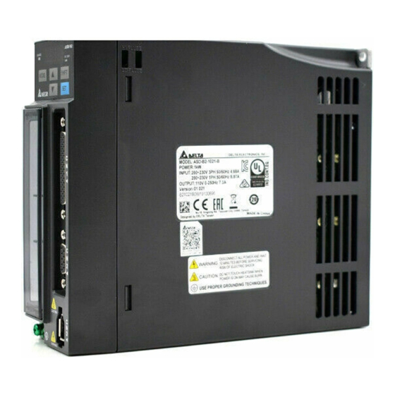
Input Power INPUT: VAC 110 A 1.55 Ins. A Rated Speed and Rated Output OUTPUT: r/min 3000 N.m 0.64 kW 0.2 Barcode C10602EST14330001 Delta Electronics, Inc. MADE IN XXXXXX Serial Number C10602ES T 14 33 0001 Model Name ... -
Page 13: Model Explanation
Inspection and Model Explanation ASDA-B2-F 1.2.2 Model Explanation ASDA-B2-F Series Servo Drive A S D - B 2 - 0 4 2 1 - F Product Name AC Servo Drive Series Rate Output Power Code Spec. - Page 14 ASDA-B2-F Inspection and Model Explanation ECMA Series Servo Motor E C M A - C 1 0 6 0 2 E S Product Name ECM: Electronic Commutation Motor Motor Type A: AC Servo Motor ...
-
Page 15: Servo Drive And Corresponding Servo Motor
Inspection and Model Explanation ASDA-B2-F Servo Drive and Corresponding Servo Motor Motor Servo Drive Max. Max. Continuous Instant- Rated Motor Output Instantaneous Output aneous Power Model Number Current Model Number Current output series current (Arms) (Arms) current ECMA-C1040F□S 0.69 2.05 ASD-B2-0121-F 0.90 2.70... -
Page 16: Each Part Of The Servo Drive
ASDA-B2-F Inspection and Model Explanation Each Part of the Servo Drive Heat sink: Used to secure servo drive and for heat dissipation. Control Circuit Terminal (L1c、L2c): Used to connect 200 ~ 230 V c, 50 / 60 Hz 1-phase / 3-phase V supply. - Page 17 Inspection and Model Explanation ASDA-B2-F (This page is intentionally left blank.) September, 2015...
-
Page 18: Installation
Installation This chapter allows you to properly install the device. Please follow the instruction mentioned in this chapter during installation. Information about specification of circuit breaker, fuse, EMI filter selection, and selection of regenerative resistor are also included. 11111111111111111111111111111111111111111111 1111111 2.1 Notes ······························································································... -
Page 19: Notes
Installation ASDA-B2-F Notes Please pay special attention to the following: Do not strain the cable connection between the servo drive and the servo motor. Make sure each screw is tightened when fixing the servo drive. The motor shaft and the ball screw should be parallel. ... -
Page 20: Installation Direction And Space
Incorrect Installing servo drives: ASDA-B2-F series servo drive should be mounted perpendicular to a dry and solid surface that conforms to NEMA standards. To ensure a well-ventilated environment, sufficient space between adjacent object and the baffle is required. 50 mm (approx. 2 inch.) of clearance is suggested. If wiring is needed, please leave the space for it. - Page 21 Installation ASDA-B2-F Installing motors: ECMA series motors shall be mounted to the mounting surface which is dry and stable. Please make sure the environment is well-ventilated and the motor is properly grounded. For the dimensions and specifications of the servo drive and servo motor, please refer to Appendix A -Specifications.
-
Page 22: Specification Of Circuit Breaker And Fuse
All electronic equipment (including servo drive) generates high or low frequency noise during operation and interfere the peripheral equipment via conduction or radiation. With EMI Filter and the correct installation, much interference can be eliminated. It is suggested to use Delta’s EMI Filter to suppress the interference better. - Page 23 Installation ASDA-B2-F General Precaution In order to ensure the best performance of EMI Filter, apart from the instructions of servo drive installation and wiring, please follow the precautions mentioned below: 1. The servo drive and EMI Filter should be installed on the same metal plate. 2.
-
Page 24: Selection Of Regenerative Resistor
There is a built-in regenerative resistor in the servo drive. Users can also use the external regenerative resistor if needed. Specification of built-in regenerative resistor provided by ASDA-B2-F Series Specification of built-in regenerative The capacity of... - Page 25 Installation ASDA-B2-F (1) Regenerative Power Selection (a) When the external load on torque does not exist If the motor operates back and forth, the energy generated by the brake will go into the capacitance of DC bus. When the voltage of the capacitance exceeds a specific value, the redundant energy will be consumed by regenerative resistor.
- Page 26 ASDA-B2-F Installation Take the motor (400 W with frame size 60) as the example, the cycle of back and forth operation is T = 0.4 sec, the maximum speed is 3000 r/min and the load inertia is 7 times to the motor inertia.
- Page 27 Installation ASDA-B2-F (2) Simple Selection Choose the appropriate regenerative resistor according to the allowable frequency and empty load frequency in actual operation. The so-called empty allowable frequency is the frequency of continuous operation when the servo motor runs from 0 r/min to the rated speed and then decelerates from the rated speed to 0r/min within the shortest time.
- Page 28 If watt is not enough when using regenerative resistor, connecting the same regenerative resistor in parallel can increase the power. Dimensions of Regenerative Resistor Delta Part Number: BR400W040 (400 W 40 Ω) MAX. WEIGHT (g) Delta Part Number: BR1K0W020 (1 kW 20 Ω) MAX.
- Page 29 Installation ASDA-B2-F (This page is intentionally left blank.) 2-12 September, 2015...
-
Page 30: Wiring
Wiring This chapter explains the wiring methods of the power circuit and connector definitions. The standard wiring diagrams for each control mode are also provided. 3.1 Connections ····················································································· 3-2 3.1.1 Connecting to Peripheral Devices ··················································· 3-2 3.1.2 Connectors and Terminals of Servo Drive ········································· 3-3 3.1.3 Wiring Method ············································································... -
Page 31: Connections
Magnetic Contactor (MC) When an alarm occurs, it outputs ALRM signal and disconnect the Host Controller power of the servo drive. It can connect to Delta’s PLC controller or other brands of NC controllers. EMI Filter CN6 Connector (DMCNET) CN1 I/O Connector... -
Page 32: Connectors And Terminals Of Servo Drive
ASDA-B2-F Wiring 3.1.2 Connectors and Terminals of Servo Drive Terminal Name Description Signal Power input of the Connect to single-phase AC power (Select the appropriate L1c, L2c control circuit voltage specification according to the product.) Power input of the main Connect to three-phase AC power (Select the appropriate R, S, T circuit... -
Page 33: Wiring Method
Wiring ASDA-B2-F 3.1.3 Wiring Method There are two types of wiring method, single-phase and three-phase. In the diagram below, Power On is contact a, Power Off and ALRM_RY are contact b. MC is the coil of magnetic contactor and self-remaining power and is the contact of main power circuit. ... -
Page 34: Specification Of Motor Power Cable
ASDA-B2-F Wiring 3.1.4 Specification of Motor Power Cable Terminal Motor Model U, V, W / Connector of Brake Definition ECMA-C1040FS (50 W) ECMA-C 0401S (100 W) ECMA-C 0602S (200 W) ECMA-C 0604S (400 W) ECMA-C 0604H (400 W) ECMA-C 08047 (400 W) ECMA-C 0807S (750 W) ECMA-C 0807H (750 W) ECMA-C 0907S (750 W) - Page 35 Wiring ASDA-B2-F CASE BRAKE1 BRAKE2 Wiring Name GROUND (Red) (White) (Black) (Yellow) (Blue) (Green) Terminal Definition A Terminal Definition B Terminal Definition C Terminal Definition D When selecting the wire rod, please choose 600 V PVC cable and the length should be no longer than 30 m.
-
Page 36: Specification Of Encoder Cable Connector
ASDA-B2-F Wiring 3.1.5 Specification of Encoder Cable Connector Encoder Connection (Diagram 1): Servo Drive Quick Connector Connector of Connector of CN2 Connector Encoder Cable Encoder Cable (Drive Side) (Motor Side) Servo Motor Note: This diagram shows the connection between the servo drive and the motor encoder, which is not drawn by the practical scale. - Page 37 Wiring ASDA-B2-F Specification and Definition of Encoder Connector: Connector of Connector of Encoder Cable Motor Encoder Motor Servo Drive Encoder View from View from this side this side (Encoder types are 17-bit and 20-bit): White Blue Reserved Reserved Reserved White/Red Blue/Black Reserved Reserved Reserved...
- Page 38 ASDA-B2-F Wiring Encoder Connection (Diagram 2): Servo Drive *1 CN2 Connector Connector of Military Encoder Cable Connector Servo Motor Note: This diagram shows the connection between the servo drive and the motor encoder, which is not drawn by the practical scale. The specification will change subject to the selected servo drive and motor model. 1.
-
Page 39: Selection Of Wiring Rod
Wiring ASDA-B2-F 3.1.6 Selection of Wiring Rod The recommended wire rods are shown as the following table. Power Wiring - Wire Diameter mm (AWG) Servo Drive and corresponding Servo Motor L1c, L2c R, S, T U, V, W P , C ECMA-C1040FS ASD-B2-0121-F ECMA-C△0401S... -
Page 40: Basic Wiring
ASDA-B2-F Wiring Basic Wiring 3.2.1 200 W or models below (without regenerative resistor nor fan) Connect to external regenerative resistor Power 1-phase/3-phase 200 ~ 230 V, 200 W and below Servo Drive IPM Module Servo Motor Encoder ±15V +3.3V GATE +24V Protection DRIVE... -
Page 41: 750 W Models (With Built-In Regenerative Resistor But No Fan)
Wiring ASDA-B2-F 3.2.2 400 W ~ 750 W models (with built-in regenerative resistor but no fan) Connect to external regenerative resistor Power 1-phase/3-phase 200 ~ 230 V, 400 W ~ 750 W Servo Drive IPM Module Servo Motor Encoder ±15 V +5 V +3.3 V GATE... -
Page 42: Kw ~ 1.5 Kw Models (With Built-In Regenerative Resistor And Fan)
ASDA-B2-F Wiring 3.2.3 1 kW ~ 1.5 kW models (with built-in regenerative resistor and fan) Connect to external regenerative resistor Power 1-phase/3-phase 200 ~ 230 V, 1 kW ~ 1.5 kW Servo Drive Models of 1 kW or above IPM Module +12 V Servo Motor... -
Page 43: Kw ~ 3 Kw Models (With Built-In Regenerative Resistor And Fan)
Wiring ASDA-B2-F 3.2.4 2 kW ~ 3 kW models (with built-in regenerative resistor and fan) Connect to external Power regenerative resistor 3-phase 200 ~ 230 V, 2 kW ~ 3 kW Models of 1 kW or above Servo Drive IPM Module +12V Servo Motor... -
Page 44: I / O Signal (Cn1) Connection
ASDA-B2-F Wiring I / O Signal (CN1) Connection 3.3.1 I / O Signal (CN1) Connector Terminal Layout In order to have a more flexible communication with the master (the host controller), 2 programmable Digital Outputs (DO) and 5 programmable digital inputs (DI) are provided. The setting of 5 digital inputs and 2 digital outputs of each axis are parameter P2-10 ~ P2-14 and parameter P2-18 ~ P2-19 respectively. -
Page 45: Signals Explanation Of Connector Cn1
Wiring ASDA-B2-F 3.3.2 Signals Explanation of Connector CN1 The following details the signals listed in previous section: General Signals Wiring Method Signal Pin No Function (Refer to 3.3.3) Position Pulse Encoder signal output A and B (Line Drive C5/C6 (Output) output) Wiring Method Signal... - Page 46 ASDA-B2-F Wiring The explanation of DI signal default setting is as the following. Wiring Method DI Signal Operation Pin No Function Mode Name (Refer to 3.3.3) When the alarm (ALRM) occurs, this signal is used to ARST reset the servo drive and enable DI.SRDY again. It is contact B and always has to be ON;...
-
Page 47: Wiring Diagrams (Cn1)
Wiring ASDA-B2-F 3.3.3 Wiring Diagrams (CN1) When the drive connects to inductive load, the diode has to be installed. (The permissible current is under 40 mA. The surge current is under 100 mA.) C1: Wiring of DO signal. The servo drive applies to C2: Wiring of DO signal. - Page 48 ASDA-B2-F Wiring PNP transistor, common emitter (E) mode (SOURCE mode) C4: The wiring of DI. The servo drive applies to the external power. Servo Drive 24 V COM+ Approx. 4.7 KΩ Caution: Do not apply to dual power or it may damage the servo drive. C5: Encoder signal output (Line driver) C6: Encoder signal output (Opto-isolator) Servo Drive...
-
Page 49: Di And Do Signal Specified By Users
Wiring ASDA-B2-F 3.3.4 DI and DO Signal Specified by Users If the default setting of DI/DO does not fulfill the requirement for the application, users can manually define the DI/DO signal. The signal function of DI 1 ~ 5, and DO1 ~ 2 is determined by parameter P2-10 ~ P2-14 and parameter P2-18 ~ P2-19 respectively. -
Page 50: Cn2 Connector
ASDA-B2-F Wiring 3.4 CN2 Connector CN2 encoder connector can be connected in two ways: CN2 Connector CN2 on drive side Encoder Connector Connect to the servo drive Connect to the motor 快速接頭 軍規接頭 The terminal block of the connector and pin number are as follows: (A) CN2 Connector 6 7 8 9 View from... - Page 51 Wiring ASDA-B2-F The definition of each signal is as follows: Drive Connector Encoder Connector Terminal Military Quick Pin No Function and Description Color Symbol Connector Connector Serial communication signal Blue input / output (+) Serial communication signal input Blue & Black / output (-) Red / Red &...
-
Page 52: Wiring Of Cn3 Connector
ASDA-B2-F Wiring Wiring of CN3 Connector Layout of CN3 Connector The servo drive can be connected to the personal computer via communication connector. Users can operate the servo drive via MODBUS, PLC or HMI. The common communication interface, RS-232, is provided and its communication distance is about 15 meters. CN3 Connector (female) Please carefully read through the description below to avoid damage or... -
Page 53: Cn6 Connector (Dmcnet)
Wiring ASDA-B2-F CN6 Connector (DMCNET) CN6 uses the standard RJ45 connector, shielded communication cable, and connects to a host controller or motion card. DMCNET system is used to implement position, torque and speed mode. It also can read or monitor the drive status. The station number of DMCNET is the same as RS-232. - Page 54 ASDA-B2-F Wiring Host Controller or Motion Card … Connect to the terminal resistor Max. axes: 12 Max. cable length: 30 m Note: The terminating resistor is suggested to use 120 Ω (Ohm) 0.25 W or above. The wiring method of concatenate more than one drives is based on two terminals of DMCNET. One is for receiving and another one is for transmission.
-
Page 55: Standard Connection Example
Wiring ASDA-B2-F 3.7 Standard Connection Example Communication Mode Servo Drive MCCB ASDA-B2-F series *2 AC 200/230 V ⊕ *4 Three-phase Regenerative 50/60 Hz Resistor White Power Supply black EMGS BRKR Green Brake *3 Encoder blue Blue/ COM+ black Twisted- pair *1... -
Page 56: Panel Display And Operation
ASDA-B2-F Panel Display and Operation Panel Display and Operation This chapter explains the panel display of ASDA-B2-F and its operation. Users may check the operation status and see whether any alarm occurs via the panel. 4.1 Panel Description ·············································································· 4-2 4.2 Parameter Setting Procedure ································································... -
Page 57: Panel Description
Panel Display and Operation ASDA-B2-F 4.1 Panel Description Display SHIFT Key MODE Key ▲ MODE SHIFT UP Key SET Key Charge LED CHARGE ▼ DOWN Key Name Function Five-/Seven-segment display is for displaying the monitoring values, Display parameter values and setting values. The group code can be changed in Parameter Mode. -
Page 58: Parameter Setting Procedure
ASDA-B2-F Panel Display and Operation 4.2 Parameter Setting Procedure Switching the mode: Power On Monitoring Mode MODE Parameter Please refer to Chapter 7 for parameters Mode 1. If no alarm occurs, the Alarm Mode will be skipped. MODE 2. When new alarm occurs, it will switch to Alarm Mode in any condition. - Page 59 Panel Display and Operation ASDA-B2-F Parameter Mode Parameter Mode Monitoring ‧‧‧ Parameter P0 SHIFT Basic ‧‧‧ Parameter P1 SHIFT Extension ‧‧‧ Parameter P2 SHIFT Communication ‧‧‧ Parameter P3 SHIFT Diagnosis ‧‧‧ Parameter P4 SHIFT Motion Control ‧‧‧ Parameter P5 MODE Monitoring Mode September, 2015...
- Page 60 ASDA-B2-F Panel Display and Operation Edit Setting Mode Parameter Mode MODE Editing Setting Mode ‧‧‧ Display parameter setting value Save the parameter setting value. Then, return to Parameter Mode. SHIFT ‧‧‧ Save the parameter setting value. SHIFT Then, return to Parameter Mode. ‧‧‧...
-
Page 61: Status Display
Panel Display and Operation ASDA-B2-F 4.3 Status Display 4.3.1 Save Setting Display When finishing editing parameter, press the SET Key to save the setting. The panel will display the setting status according to the setting for a second. Displayed Symbol Description The setting value is saved correctly. -
Page 62: Positive And Negative Sign Setting
ASDA-B2-F Panel Display and Operation 4.3.4 Positive and Negative Sign Setting Displayed Symbol Description When entering the Editing Setting Mode, pressing the UP / DOWN Key can change the displayed value. The SHIFT Key can change the carry value users wish to alter. - Page 63 Panel Display and Operation ASDA-B2-F P0-02 Monitor Displayed Setting Description Unit Symbol Value Peak torque Main circuit voltage [Volt] Load / Motor inertia ratio (Note: If it shows 13.0, it [1 times] means the actual inertia is 13) [°C] IGBT temperature Resonance frequency (Low byte is the first resonance [Hz] and high byte is the second one).
- Page 64 ASDA-B2-F Panel Display and Operation Example of the Status Description displayed value If the value is 1234, it displays 01234 (shows in decimal format). (Dec) 16 bits If the value is 0x1234, it displays 1234 (shows in hexadecimal format; the first digit does not show any). (Hex) If the value is 1234567890, the display of the high byte is (Dec high)
-
Page 65: General Function
Panel Display and Operation ASDA-B2-F 4.4 General Function 4.4.1 Operation of Fault Record Display When it is in Parameter Mode, select P4-00 ~ P4-04 and press the SET Key, the corresponding fault record will be shown. The 1 recent error The 2 recent error The 3... -
Page 66: Jog Mode
ASDA-B2-F Panel Display and Operation 4.4.2 JOG Mode When it is in Parameter Mode, select P4-05 and follow the setting method below for JOG operation. Press the SET Key to display the speed of JOG. The default value is 20 r/min. Press the UP or DOWN Key to adjust the desired speed of JOG. - Page 67 Panel Display and Operation ASDA-B2-F 4.4.3 Force DO On Enter the Diagnosis Mode by the following settings. Set P2-08 to 406 and enable the function of force DO on. Then, set the forced DO by binary method via P4-06. When the setting value is 2, it will force to enable DO2.
-
Page 68: Digital Input Diagnosis Operation
ASDA-B2-F Panel Display and Operation 4.4.4 Digital Input Diagnosis Operation Enter the Diagnosis Mode – DI by the following setting methods. When the external output signal DI1 ~ DI5 is ON, the corresponding signal will be shown on the panel. It is displayed by bit. When it shows bit, it means the DI is ON. -
Page 69: Digital Output Diagnosis Operation
Panel Display and Operation ASDA-B2-F 4.4.5 Digital Output Diagnosis Operation Enter the Diagnosis Mode – DO by the following setting methods. The output signal DO1 ~ DO2 is ON and the corresponding signal will be shown on the panel. It is displayed by bit. When it shows 1, it means the DO is ON. -
Page 70: Trial Operation And Tuning
Trial Operation and Tuning This chapter illustrates how to do trial operation and the basic procedure of tuning. For your safety, please conduct the first inspection (without load) and then carry out further trial with load. 5.1 Inspection without Load ······································································ 5-2 5.2 Apply Power to the Servo Drive ····························································... -
Page 71: Inspection Without Load
The encoder cable should avoid excessive stress. When the motor is running, make sure the cable is not frayed or over extended. Please contact with Delta if there is any vibration of the servo motor or unusual noise during the operation. ... -
Page 72: Apply Power To The Servo Drive
ASDA-B2-F Trial Operation and Tuning 5.2 Apply Power to the Servo Drive Please follow the instructions below. A. Make sure the wiring between the motor and servo drive is correct: U, V, W and FG have to connect to cable red, white, black and green respectively. If the wiring is incorrect, the motor cannot work normally. - Page 73 Trial Operation and Tuning ASDA-B2-F (1) When the screen displays Warning of overvoltage: It means the voltage input by the main circuit is higher than the rated range or a power input error has occurred (incorrect power system). Corrective action: ...
- Page 74 ASDA-B2-F Trial Operation and Tuning (3) When screen displays Warning of emergency stop: Please check if any of the digital input DI1 ~ DI5 is set to emergency stop (EMGS). Corrective action: If not desire to set emergency stop (EMGS) as one of the digital input, make sure no digital input is set to emergency stop (EMGS) among DI1 ~ DI5.
- Page 75 Trial Operation and Tuning ASDA-B2-F If the function of positive limit (PL) is needed and this DI is set as normally close (function code: 0x0023), please make sure this DI is always normally close. If not, please set this DI as normally open (function code: 0x0123).
-
Page 76: Jog Trial Run Without Load
ASDA-B2-F Trial Operation and Tuning 5.3 JOG Trial Run without Load It is very convenient to test the motor and servo drive with the method of JOG trial run without load since the extra wiring is unnecessary. For safety reasons, it is recommended to set JOG at low speed. -
Page 77: Trial Run Without Load (Speed Mode)
(DI4) and emergency stop (DI5). Thus, parameter P2-14 is set to 0 (Disabled); DI3 and DI4 are set to Speed Selection (SPD0) and Speed Selection (SPD1) respectively. The digital input of Delta’s servo drive can be programmed by users. When programming digital input, please refer to the description of DI code. - Page 78 ASDA-B2-F Trial Operation and Tuning The speed command selection is determined by SPD0 and SPD1. See the table below. DI signal of CN1 Speed Command Source Content Range Command No. SPD1 SPD0 Speed command is zero P1-09 -60000 ~ 60000 Register P1-10 -60000 ~ 60000...
-
Page 79: Tuning Procedure
Trial Operation and Tuning ASDA-B2-F 5.5 Tuning Procedure Estimate the inertia ratio: JOG Mode 1. After completing wiring, when applying to the power, the servo drive will AL013 display: P0-00 2. Press the MODE key to select the mode of parameter function. P2-00 3. -
Page 80: Flowchart Of Tuning Procedure
ASDA-B2-F Trial Operation and Tuning 5.5.1 Flowchart of Tuning Procedure Trial run without load is OK. New model? Exit the control of the host controller. If the estimation of inertia ratio is Use the servo drive to perform trial incorrect, it cannot obtain the best run and estimate the inertia ratio* performance of tuning. -
Page 81: Inertia Estimation Flowchart (With Mechanism)
Trial Operation and Tuning ASDA-B2-F 5.5.2 Inertia Estimation Flowchart (with Mechanism) Turn Off the power of servo drive. Connect the motor to the mechanism. Turn On the power of servo drive. Set P0-02 to 15. The panel will display inertia ratio. Set P2-32 to 0 in manual mode. -
Page 82: Flowchart Of Auto Tuning
ASDA-B2-F Trial Operation and Tuning 5.5.3 Flowchart of Auto Tuning Please refer to the figure below to start the auto tuning procedure. Servo off. Set P2-32 to 1. Then, Servo on. Set P0-02 to 15. The panel will display the inertia ratio*. Alternately accelerate and decelerate. -
Page 83: Flowchart Of Semi-Auto Tuning
Trial Operation and Tuning ASDA-B2-F 5.5.4 Flowchart of Semi-Auto Tuning Please refer to the figure below to start the semi-auto tuning procedure. Servo off and set P2-32 to 2. Then, servo on again. Set P0-02 to 15. The panel displays the inertia ratio*. The servo drive issues the command and make motor alternately accelerate /... -
Page 84: Limit Of Inertia Ratio
ASDA-B2-F Trial Operation and Tuning 5.5.5 Limit of Inertia Ratio Please see the limit of inertia ratio below during the estimation. Acceleration / Deceleration time of reaching 2000 r/min should be less than 1 second. The speed in forward and reverse direction should be higher than 200 r/min. ... - Page 85 Trial Operation and Tuning ASDA-B2-F Motor alternately accelerates and decelerates High-frequency Complete resonance? Set P2-47 to 1 Resonance Repeatedly set P2-47 elimminated? to 1 for over 3 times Note 1 Set P2-47 to 0 P2-47 is set to 0 P2-44 = 32 (max); Remain the value of P2-43 P2-46 = 32 (max) Complete...
-
Page 86: Mechanical Resonance Suppression Method
ASDA-B2-F Trial Operation and Tuning 5.5.6 Mechanical Resonance Suppression Method Three groups of Notch filter are provided to suppress mechanical resonance. Both two of them can be set to the auto resonance suppression and manual adjustment. Use the analytic tool provided by PC software to display the point of resonance. -
Page 87: Tuning Mode And Parameters
Trial Operation and Tuning ASDA-B2-F 5.5.7 Tuning Mode and Parameters Auto-set Tuning mode P2-32 User-defined parameters Inertia adjustment parameters P1-37(Inertia ratio of the motor) P2-00 (Position control gain) P2-04 (Speed control gain) P2-06(Speed integral Manual mode 0 (default) The value remains compensation) P2-25(Low-pass filter of resonance suppression) -
Page 88: Tuning In Manual Mode
ASDA-B2-F Trial Operation and Tuning 5.5.8 Tuning in Manual Mode The selection of position / speed response frequency should be determined by the machinary stiffness and application. Generally, the high-frequency machinary or the one requries precise processing needs the higher response frequency. However, it might cause the resonance. Thus, use machinery with higher stiffness is needed so as to avoid resonance. - Page 89 Trial Operation and Tuning ASDA-B2-F Speed integral compensation (KVI, parameter P2-06) The higher the KVI value is, the better capability of eliminating the deviation will be. However, if the value is set too high, it might easily cause vibration of machinery. It is suggested to set the value as follows.
- Page 90 Control Mode of Operation This chapter describes operation structure of each control mode, including information about gain adjustment and filters. The operation of ASDA-B2-F is based on communication. Its position mode is controlled via DMCNET network and the speed mode and torque mode only accept commands from internal registers. 6.1 Selection of Operation Mode ································································...
-
Page 91: Selection Of Operation Mode
Control Mode of Operation ASDA-B2-F 6.1 Selection of Operation Mode Three basic operation modes are provided in B2-F series servo drive, position, speed and torque. The following table lists all the operation modes and the related descriptions. Short Setting Mode Name Description Name Code... -
Page 92: Position Mode
ASDA-B2-F Control Mode of Operation 6.2 Position Mode Position mode can be used in the application which requires precise positioning function, such as machinery industry. ASDA-B2-F only provides position mode which can be controlled via communication network DMCNET. 6.2.1 Control Structure of Position Mode Position Command Position Command... -
Page 93: S-Curve Filter (Position)
Control Mode of Operation ASDA-B2-F 6.2.2 S-curve Filter (Position) S-curve filter smoothes the motion command. With S-curve filter, the speed and the process of acceleration become more continuous and the jerk will be smaller. It not only improves the performance when motor accelerates/decelerates, but also smoothes the mechanical operation. If the load inertia increases, the operation of the motor will be influenced by friction and inertia when it starts or stops the rotation. -
Page 94: Electronic Gear Ratio
ASDA-B2-F Control Mode of Operation Relevant Parameters (Please refer to Chapter 7 for detailed description): Parameter Abbr. Function P1-34 TACC Acceleration Constant of S-Curve P1-35 TDEC Deceleration Constant of S-Curve P1-36 Acceleration/Deceleration Constant of S-Curve 6.2.3 Electronic Gear Ratio Relevant Parameters (Please refer to Chapter 7 for detailed description): Parameter Abbr. -
Page 95: Low-Pass Filter
Control Mode of Operation ASDA-B2-F 6.2.4 Low-pass Filter Relevant Parameters (Please refer to Chapter 7 for detailed description): Parameter Abbr. Function P1-08 PRLT Smooth Constant of Position Command (Low-pass Filter) P1-45 Gear Ratio (Denominator) (M) Target Position 6.2.5 Gain Adjustment of Position Loop Before setting the position control unit, users have to manually complete the setting of tuning mode selection (P2-32) since the speed loop is included in position loop. -
Page 96: Low-Frequency Vibration Suppression In Position Mode
ASDA-B2-F Control Mode of Operation Position Control Unit Smooth Constant of Position Feed Position Feed Forward Gain Differentiator Forward Gain P2-02 P2-03 Position Loop Max. Speed Gain Limit P2-00 P1-55 Switching Rate Gain Switching of Position Loop and Switching Gain Selection P2-01 Speed... - Page 97 Control Mode of Operation ASDA-B2-F frequency has been detected. Please decrease the value of P1-30 and set P1-29 to 1 so as to search for the vibration frequency again. Please note that when the detection level is set to be too small, the noise may be regarded as the frequency of low-frequency vibration.
- Page 98 ASDA-B2-F Control Mode of Operation Relevant Parameters of Auto Vibration Suppression (Please refer to Chapter 7 for detailed description): Parameter Abbr. Function P1-29 AVSM Auto Low-frequency Vibration Suppression Setting P1-30 Low-frequency Vibration Detection P1-30 is to set the range to detect the magnitude of low-frequency vibration. When the frequency is not being detected, it is probably because the value of P1-30 is set to be too large which exceeds the range of vibration.
-
Page 99: Speed Mode
Control Mode of Operation ASDA-B2-F 6.3 Speed Mode Speed control mode is applicable in situation which requires precise speed control, such as CNC machine tools. The command input of ASDA-B2-F is register. Two ways are provided to use register input. One is to set different values of speed command to the three registers before operation, and use DI.SP0 and SP1 in CN1 for switching. -
Page 100: Control Structure Of Speed Mode
ASDA-B2-F Control Mode of Operation 6.3.2 Control Structure of Speed Mode Speed Command Speed Command Processing Unit Speed Estimator Resonance Current Speed Control Unit Torque Limit Motor Suppression Unit Loop Figure 6-5 Basic Control Structure of Speed Mode The speed command processing unit is to select speed command source according to Section 6.3.1, including the S-curve setting for smoothing speed command. -
Page 101: Smooth Speed Command
Control Mode of Operation ASDA-B2-F 6.3.3 Smooth Speed Command S-curve Filter During the process of acceleration or deceleration, S-curve filter applies the program of three-stage acceleration curve for smoothing the motion command, which generates continuous acceleration. It is for avoiding the jerk (the differentiation of acceleration) of sudden command change which further causes mechanical vibration and noise. -
Page 102: Timing Diagram Of Speed Mode
ASDA-B2-F Control Mode of Operation Command End Low-pass Filter It is usually used to eliminate the unwanted high-frequency response or noise. It also can smooth the command. Relevant Parameters (Please refer to Chapter 7 for detailed description): Parameter Abbr. Function Acceleration/Deceleration Smooth Constant of Speed P1-06 SFLT... -
Page 103: Gain Adjustment Of Speed Loop
Control Mode of Operation ASDA-B2-F 6.3.5 Gain Adjustment of Speed Loop Here introduces the function of speed control unit. The following shows its structure: Speed Control Unit Speed Feed Differentiator Forward Gain System Inertia J P2-07 (1+P1-37)*JM Speed Loop Gain P2-04 Integrator Gain Switching... - Page 104 ASDA-B2-F Control Mode of Operation Relevant Parameters (Please refer to Chapter 7 for detailed description): Parameter Abbr. Function P2-04 Speed Loop Gain P2-06 Speed Integral Compensation P2-07 Speed Feed Forward Gain Theoretically, stepping response can be used to explain speed loop gain (KVP), speed integral compensation (KVI) and speed feed forward gain (KVF).
- Page 105 Control Mode of Operation ASDA-B2-F Time Domain The bigger KVP value causes higher bandwidth and shortens the rising time. However, if the value is set to be too big, the phase margin will be too small. To steady-state following error, the result is not as good as KVI.
- Page 106 ASDA-B2-F Control Mode of Operation If the KVF value closes to 1, the feed forward compensation will be more complete and the dynamic following error will become smaller. However, if the KVF value is set to be too big, it would cause vibration. Generally, instrument is needed when applying frequency domain for measurement.
-
Page 107: Resonance Suppression
Control Mode of Operation ASDA-B2-F 6.3.6 Resonance Suppression When resonance occurs, it is probably because the stiffness of the control system is too strong or the response bandwidth is too fast. Eliminating these two factors might improve the situation. In addition, low-pass filter (P2-25) and notch filter (P2-23 and P2-24) are provided to suppress the resonance without changing the control parameters. - Page 108 ASDA-B2-F Control Mode of Operation bigger than 0. If it is, it means the frequency points in P2-43 and P2-45 are the ones found by auto resonance suppression. If the value is 0, it means the value of 1000 in P2-43 and P2-45 are default values which are not the ones found by auto resonance suppression.
- Page 109 Control Mode of Operation ASDA-B2-F Drive the machine by servo system Check if resonance occurs Set P2-47 = 1 Check if resonance occurs Set P2-47 = 1 for three times Decrease frequency P2-44 = 32 bandwidth or P2-46 = 32 Set P2-47 = 0 If P2-44 >0, the value of P2-44 should +1 If P2-46 >0, the value of P2-46 should +1...
- Page 110 ASDA-B2-F Control Mode of Operation Here illustrates the effect via low-pass filter (parameter P2-25). The following figure is the system open-loop gain with resonance. Gain Frequency When the value of low-pass filter (parameter P2-25) is increased from 0, BW becomes smaller (See the following figure).
- Page 111 Control Mode of Operation ASDA-B2-F Resonance suppression with low-pass filter: Gain Gain Gain Resonance Point Resonance condition is suppressed Attenuation Rate - Low-pass filter 0 db Cut-off frequency of low-pass filter =1000/P2-25Hz Frequency Frequency Frequency Resonance Resonance Frequency Frequency When the value of low-pass filter (P2-25) is increased from 0, B.W. becomes smaller. Although it improves the situation of resonance, the response bandwidth and phase margin are reduced as well.
-
Page 112: Torque Mode
ASDA-B2-F Control Mode of Operation 6.4 Torque Mode Torque control mode is appropriate in torque control application, such as printing machine and winding machine. The command source is from register input which uses internal parameters (P1-12 ~ P1-14) as torque commands. 6.4.1 Selection of Torque Command Torque commands come from the internal parameters of registers. -
Page 113: Control Structure Of Torque Mode
Control Mode of Operation ASDA-B2-F 6.4.2 Control Structure of Torque Mode Output Torque Torque Torque Resonance Current Control Command Motor Suppression Unit Command Processing Unit Unit Current Sensor Figure 6-11 Basic Control Structure of Torque Mode The torque command processing unit is to select torque command source according to Section 6.4.1, including the S-curve setting for torque command. -
Page 114: Smooth Torque Command
ASDA-B2-F Control Mode of Operation 6.4.3 Smooth Torque Command Relevant Parameters (Please refer to Chapter 7 for detailed description): Parameter Abbr. Function P1-07 TFLT Smooth Constant of Torque Command (Low-pass Filter) 目標 速 度 Target Speed TFLT 6.4.4 Timing Diagram of Torque Mode Figure 6-13 Timing Diagram of Torque Mode Note: OFF means the contact is opened;... -
Page 115: The Use Of Brake
Control Mode of Operation ASDA-B2-F 6.5 The Use of Brake When operating brake via servo drive, if DO.BRKR is set to OFF, it means the brake is not working and the motor is locked. If DO.BRKR is set to ON, it means the brake is working and the motor can operate freely. - Page 116 ASDA-B2-F Control Mode of Operation Servo Drive Do not connect VDD-COM+ DOX: (DOX+,DOX-) Ensure the polarity of the diode is correct, or it When emergency stop signal is X=1,2,3,4,5 might damage the drive activated, this circuit breaker will Motor be enabled DO1: (7,6) Brake 1 (Blue) DO2: (5,4)
- Page 117 Control Mode of Operation ASDA-B2-F (This page is intentionally left blank.) 6-28 September, 2015...
- Page 118 Parameters This chapter provides descriptions of parameter setting and definition of digital input (DI) and digital output (DO). Users can set functions via different parameters. 7.1 Parameter Definition ·········································································· 7-2 7.2 List of Parameters ············································································· 7-3 7.3 Parameter Description ······································································ 7-10 P0-xx Monitor Parameters ··································································...
-
Page 119: Parameter Definition
Parameters ASDA-B2-F 7.1 Parameter Definition Parameters are divided into five groups which are shown as follows. The first character after the start code P is the group character and the following two characters are parameter character. As for the communication address, it is the combination of group character along with two digit numbers in hexadecimal format. -
Page 120: List Of Parameters
ASDA-B2-F Parameters 7.2 List of Parameters Monitor and General Output Parameter Control Mode Related Parameter Abbr. Function Default Unit Section DMC Sz Factory P0-00★ Firmware Version Setting Alarm Code Display of Drive P0-01■ (Seven-segment Display) P0-02 Drive Status P0-08★ TSON Servo On Time Hour P0-09★... - Page 121 Parameters ASDA-B2-F Monitor and General Output Parameter Control Mode Related Parameter Abbr. Function Default Unit Section DMC Sz Target Setting of Mapping Parameter P0-39 MAP5A 4.3.5 P0-29 Target Setting of Mapping Parameter P0-40 MAP6A 4.3.5 P0-30 Target Setting of Mapping Parameter P0-41 MAP7A 4.3.5...
- Page 122 ASDA-B2-F Parameters Filter and Resonance Suppression Parameter Control Mode Related Parameter Abbr. Function Default Unit Section DMC Sz Tz Resonance Suppression (Notch Filter) P2-24 DPH1 6.3.6 Attenuation Rate (1) Resonance Suppression (Notch Filter) P2-43 NCF2 1000 6.3.6 Resonance Suppression (Notch Filter) P2-44 DPH2 6.3.6...
- Page 123 Parameters ASDA-B2-F Gain and Switch Parameter Control Mode Related Parameter Abbr. Function Default Unit Section DMC Sz P2-27 GCC Gain Switching and Switching Selection P2-28 GUT Gain Switching Time Constant 10 ms pulse P2-29 GPE Gain Switching 1280000 Kpps r/min Speed Loop Frequency Response P2-31■...
- Page 124 ASDA-B2-F Parameters Speed Control Parameter Control Mode Related Parameter Abbr. Function Default Unit Section DMC Sz pulse Input Setting of Control Mode and P1-01● r/min Table Control Command Table P1-02▲ PSTL Speed and Torque Limit Setting Polarity Setting of Encoder Pulse P1-03 AOUT Output...
- Page 125 Parameters ASDA-B2-F Planning of Digital Input / Output Pin and Output Setting Parameter Control Mode Related Parameter Abbr. Function Default Unit Section DMC Sz Tz General Range Compare Digital Output P0-53 ZDRT - Filtering Time General Range Compare Digital Output P0-54 ZON1L - Lower Limit of 1...
- Page 126 ASDA-B2-F Parameters P3-05 CMM Communication Mechanism P3-06■ Control Switch of Digital Input (DI) P3-07 Communication Response Delay Time 0.5 ms P3-08 MNS Monitor Mode P3-09 DMCNET Synchronize Setting 3511 P3-10 CANEN DMCNET Protocol Setting P3-11 CANOP DMCNET Selection P3-12 QSTPO DMCNET Support Setting (★) Read-only register, can only read the status.
-
Page 127: Parameter Description
Parameters ASDA-B2-F 7.3 Parameter Description P0-xx Monitor Parameters Address: 0000H P0-00★ Firmware Version 0001H Operational Related Panel / Software Communication Interface: Section: Control Default: Factory Setting Mode: Unit: - Range: - Format: DEC Data Size: 16-bit Settings: This parameter shows the firmware version of the servo drive. Alarm Code Display of Drive (Seven-segment Address: 0002H P0-01■... - Page 128 ASDA-B2-F Parameters Alarm of Servo Drive Code Description Code Description Incorrect wiring of the motor power cable U, V, W (Incorrect wiring of motor power Encoder under voltage cable U, V, W, GND) Internal communication of the encoder is The multiturn of absolute encoder overflows in error Warning of servo drive function overload Wrong motor type...
- Page 129 Parameters ASDA-B2-F P0-03~P0-07 Reserved Address: 0010H P0-08★ TSON Power On Time 0011H Operational Related Panel / Software Communication Interface: Section: Control Default: 0 Mode: Unit: Hour Range: 0 ~ 65535 Format: DEC Data Size: 16-bit Settings: It shows the total start up time of the servo drive. Address: 0012H P0-09★...
- Page 130 ASDA-B2-F Parameters The setting value which is set by P0-20 should be monitored via P0-12. (Please refer to P0-02) Users need to access the address via communication port to read the status. Set P0-02 to 26. The panel displays “VAR-4” first, and then shows the content of P0-12. Address: 001AH P0-13★...
- Page 131 Parameters ASDA-B2-F Address: 002AH P0-21 CM5A Status Monitor Register 5 Selection 002BH Operational Related Panel / Software Communication Interface: Section: Control Default: 0 Mode: Unit: - Range: 0 ~ 127 Format: DEC Data Size: 16-bit Settings: Please refer to the description of P0-02 for the setting value. P0-22~P0-24 Reserved Address: 0032H...
- Page 132 ASDA-B2-F Parameters Address: 003AH P0-29 MAP5 Mapping Parameter# 5 003BH Operational Related Panel / Software Communication 4.3.5 Interface: Section: Control Default: No need to initialize Mode: Determined by the corresponding Unit: - Range: parameter of P0-39 Format: HEX Data Size: 32-bit Settings: The using method is the same as P0-25.
- Page 133 Parameters ASDA-B2-F P0-35: Mapping parameter: P0-35; Mapping content: P0-25 When PH≠PL, it means the content of P0-25 includes two 16-bit parameters. VH=*(PH), VL=*(PL) Mapping parameter: P0-35; Mapping content: P0-25 When PH=PL=P, it means the content of P0-25 includes one 32-bit parameter. V32=*(P) If P=060Ah (P6-10), then V32 is P6-10.
- Page 134 ASDA-B2-F Parameters Address: 004CH P0-38 MAP4A Target Setting of Mapping Parameter P0-28 004DH Operational Related Panel / Software Communication 4.3.5 Interface: Section: Control Default: 0 Mode: Determined by the communication Unit: - Range: address of the parameter group Format: HEX Data Size: 32-bit Settings: Address: 004EH...
- Page 135 Parameters ASDA-B2-F Address: 0054H P0-42 MAP8A Target Setting of Mapping Parameter P0-32 0055H Operational Related 4.3.5 Panel / Software Communication Interface: Section: Control Default: 0 Mode: Determined by the communication Unit: - Range: address of the parameter group Format: HEX Data Size: 32-bit Settings: P0-43...
- Page 136 ASDA-B2-F Parameters Function Function HOME (Homing finished) Reserved OLW (Early warning for overload) Reserved WARN (When servo warning, CW, CCW, EMGS, under Reserved voltage or communication error occurs, DO is ON) Reserved Reserved Address: 0062H P0-49■ Renew Encoder Absolute Position 0063H Operational Related...
- Page 137 Parameters ASDA-B2-F Encoder Absolute Position (Pulse number within Address: 0068H P0-52★ single turn or PUU) 0069H Operational Related Panel / Software Communication Interface: Section: Control Default: 0 Mode: Range: 0 ~ 1280000-1 (pulse number) Unit: Pulse or PUU -2147483648 ~ 2147483647 (PUU) Format: DEC Data Size: 32-bit Settings:...
- Page 138 ASDA-B2-F Parameters General Range Compare Digital Output - Upper Address: 006EH P0-55 ZON1H Limit of 1 Monitoring Variable 006FH Operational Related Panel / Software Communication Interface: Section: Control Default: 0 Mode: Unit: - Range: -2147483648 ~ +2147483647 Format: DEC Data Size: 32-bit Settings: If the value of parameter P0-09 changes within the range set by P0-54 and P0-55, its value will be outputted after the filtering time determined by parameter P0-53.X.
-
Page 139: P1-Xx Basic Parameters
Parameters ASDA-B2-F P1-xx Basic Parameters P1-00▲ Reserved Input Setting of Control Mode and Control Address: 0102H P1-01● Command 0103H Operational Related Panel / Software Communication Section: 6.1, Table 7.1 Interface: Control Default: 0B Mode: Unit: P (pulse); S (r/min); T (N-M) Range: 00 ~ 110F Format: HEX Data Size: 16-bit... - Page 140 ASDA-B2-F Parameters Address: 0104H P1-02▲ PSTL Speed and Torque Limit Setting 0105H Operational Related Panel / Software Communication Section: Table 7.1 Interface: Control Default: 0 Mode: Unit: - Range: 00 ~ 11 Format: HEX Data Size: 16-bit Settings: Disable / Enable speed limit function Disable / Enable torque limit function Not in use ...
- Page 141 Parameters ASDA-B2-F Acceleration / Deceleration Smooth Constant of Address: 010CH P1-06 SFLT Speed Command (Low-pass Filter) 010DH Operational Related Panel / Software Communication 6.3.3 Interface: Section: Control Default: 0 Mode: Unit: ms Range: 0 ~ 1000 Format: DEC Data Size: 16-bit Settings: 0: Disabled Smooth Constant of Torque Command (Low-pass...
- Page 142 ASDA-B2-F Parameters Settings: Internal Speed Command 2: The setting of the 2 internal speed command Internal Speed Limit 2: The setting of the 2 internal speed limit Example of inputting internal speed limit: Speed Limit Setting Allowable Speed Forward Speed Reverse Speed Value of P1-10 Range...
- Page 143 Parameters ASDA-B2-F Example of inputting internal torque limit: Torque Limit Setting Allowable Torque Forward Torque Reverse Torque Value of P1-13 Range Limit Limit -30 ~ 30 % 30 % -30 % Internal Torque Command 3 / Internal Torque Address: 011CH P1-14 Limit 3 011DH...
- Page 144 ASDA-B2-F Parameters Address: 0136H P1-27 VSF2 Low-frequency Vibration Suppression (2) 0137H Operational Related Panel / Software Communication 6.2.6 Interface: Section: Control Default: 1000 DMCNET Mode: Unit: 0.1 Hz Range: 10 ~ 1000 Format: DEC Data Size: 16-bit Example: 150 = 15 Hz Settings: The setting value of the second low-frequency vibration suppression.
- Page 145 Parameters ASDA-B2-F Address: 0140H P1-32 LSTP Motor Stop Mode 0141H Operational Related Panel / Software Communication Interface: Section: Control Default: 0 Mode: Unit: - Range: 0 ~ 20 Format: HEX Data Size: 16-bit Settings: Not in use Selection of executing dynamic brake Not in use ...
- Page 146 ASDA-B2-F Parameters Address: 0148H P1-36 Acceleration / Deceleration Constant of S-Curve 0149H Operational Related Panel / Software Communication 6.3.3 Interface: Section: Control Default: 0 Sz, DMCNET Mode: Unit: ms Range: 0 ~ 65500 (0: Disable this function) Format: DEC Data Size: 16-bit Settings: Acceleration / Deceleration Constant of S-Curve: P1-34: Set the acceleration time of acceleration / deceleration of trapezoid curve.
- Page 147 Parameters ASDA-B2-F Address: 014CH P1-38 ZSPD Zero Speed Range Setting 014DH Operational Related Panel / Software Communication Table 7.2 Interface: Section: Control Default: 10.0 Mode: Unit: 1 r/min Data Size: 16-bit 0.1 r/min Range: 0.0 ~ 200.0 0 ~ 2000 Format: One decimal Example: 1.5 = 1.5 r/min 15 = 1.5 r/min...
- Page 148 ASDA-B2-F Parameters Address: 0158H P1-44▲ Gear Ratio (Numerator) (N1) 0159H Operational Related Panel / Software Communication 6.2.3 Interface: Section: Control Default: 128 DMCNET Mode: Unit: Pulse Range: 1 ~ (2 Format: DEC Data Size: 32-bit Settings: Please refer to P2-60 ~ P2-62 for the setting of multiple gear ratio (numerator). Note: In DMCNET mode, the setting value can only be modified when Servo Off.
- Page 149 Parameters ASDA-B2-F When the deviation between speed command and motor feedback speed is smaller than the value of this parameter, then the digital output DO.SP_OK (DO code is 0x19) is ON. Block diagram: 1. Speed Command 2. Feedback Speed 3. Obtain Absolute Value 4.
- Page 150 ASDA-B2-F Parameters 4. DO.TPOS: It means the position error of the servo drive is within the value of P1-54. 5. DO.MC_OK: It means the position command is completely outputted and the servo finishes positioning. MC_OK is ON if CMD_OK and TPOS are both ON. 6.
- Page 151 Parameters ASDA-B2-F 1.5 kW 2 kW 3 kW Following describes the setting value of P1-52 and P1-53 when connecting regenerative resistor with different method: External regenerative resistor Setting: P1-52 = 10 (Ω) 1 kW, 10 Ω P1-53 = 1000 (W) External regenerative resistor (serial connection) 1 kW, 10 Ω...
- Page 152 ASDA-B2-F Parameters Address: 0170H P1-56 Output Overload Warning Level 0171H Operational Related Panel / Software Communication Interface: Section: Control Default: 120 Mode: Unit: % Range: 0 ~ 120 Format: DEC Data Size: 16-bit Settings: The range of the setting value is 0 ~ 100. If the torque outputted by the servo motor is continuously higher than the setting proportion (P1-56), the early warning for overload (DO is set to 10, OLW) will occur.
- Page 153 Parameters ASDA-B2-F Settings: Set up the smooth constant of friction compensation. P1-64 ~ P1-67 Reserved Address: 0188H P1-68 PFLT2 Position Command Moving Filter 0189H Operational Related Panel / Software Communication Interface: Section: Control Default: 4 DMCNET Mode: Unit: ms Range: 0 ~ 100 Format: DEC Data Size: 16bit Settings:...
-
Page 154: P2-Xx Extension Parameters
ASDA-B2-F Parameters P2-xx Extension Parameters Address: 0200H P2-00 Position Loop Gain 0201H Operational Related Panel / Software Communication 6.2.5 Interface: Section: Control Default: 35 DMCNET Mode: Unit: rad/s Range: 0 ~ 2047 Format: DEC Data Size: 16-bit Settings: Increasing the value of position loop gain can enhance the position response and diminish the deviation of position control. - Page 155 Parameters ASDA-B2-F Address: 020AH P2-05 Switching Rate of Speed Loop Gain 020BH Operational Related Panel / Software Communication Interface: Section: Control Default: 100 Mode: Unit: % Range: 10 ~ 500 Format: DEC Data Size: 16-bit Settings: Switch the changing rate of speed loop gain according to the gain switching condition. Address: 020CH P2-06 Speed Integral Compensation...
- Page 156 ASDA-B2-F Parameters Settings: When the environmental noise is big, increasing the setting value can enhance the control stability. However, if the value is set to be too big, the response time will be influenced. Address: 0214H P2-10 DI1 Functional Planning 0215H Operational Related...
- Page 157 Parameters ASDA-B2-F Address: 021AH P2-13 DI4 Functional Planning 021BH Operational Related Panel / Software Communication Table 7.1 Interface: Section: Control Default: 023 Mode: 0~ 0x15F (The last two codes are Unit: - Range: DI code) Format: HEX Data Size: 16-bit Settings: Please refer to the description of P2-10.
- Page 158 ASDA-B2-F Parameters P2-20~P2-22 Reserved Address: 022EH P2-23 NCF1 Resonance Suppression (Notch Filter) (1) 022FH Operational Related Panel / Software Communication 6.3.6 Interface: Section: Control Default: 1000 Mode: Unit: Hz Range: 50 ~ 1000 Format: DEC Data Size: 16-bit Settings: The first setting value of resonance frequency. If P2-24 is set to 0, this function is disabled. P2-43 and P2-44 are for the second notch filter.
- Page 159 Parameters ASDA-B2-F Address: 0236H P2-27 Gain Switching and Switching Selection 0237H Operational Related Panel / Software Communication Interface: Section: Control Default: 0 Mode: Unit: - Range: 0x0000 ~ 0x0018 Format: HEX Data Size: 16-bit Settings: Gain switching conditon Gain switching method Not in use ...
- Page 160 ASDA-B2-F Parameters Address: 023CH P2-30■ Auxiliary Function 023DH Operational Related Panel / Software Communication Interface: Section: Control Default: 0 Mode: Unit: - Range: -8 ~ +8 Format: DEC Data Size: 16-bit Settings: Disable all the functions described below. Use the software to force servo on. 2 ~ 4 (Reserved) This setting allows the written parameters not to retain after power-off.
- Page 161 Parameters ASDA-B2-F Settings: 0: Manual Mode 1: Auto Mode (continuous adjustment) 2: Semi-auto Mode (non-continuous adjustment) Description of manual mode setting: When P2-32 is set to 0, parameters related to gain control, such as P2-00, P2-02, P2-04, P2-06, P2-07, P2-25 and P2-26, all can be set by the user. When switching mode from auto or semi-auto mode to manual mode, gain-related parameters will be updated automatically.
- Page 162 ASDA-B2-F Parameters Condition of Excessive Position Control Address: 0246H P2-35 PDEV Deviation Warning 0247H Operational Related Panel / Software Communication Interface: Section: Control Default: 3840000 DMCNET Mode: Unit: Pulse Range: 1 ~ 128000000 Format: DEC Data Size: 32-bit Settings: It is the setting of excessive position control deviation warning in servo drive error display (P0-01). P2-36~P2-42 Reserved Address: 0256H...
- Page 163 Parameters ASDA-B2-F Address: 025EH P2-47 ANCF Auto Resonance Suppression Mode Setting 025FH Operational Related Panel / Software Communication Interface: Section: Control Default: 1 Mode: Unit: - Range: 0 ~ 2 Format: DEC Data Size: 16-bit Settings: 0: The auto-detection function is disabled. 1: Set back to 0 after resonance suppression.
- Page 164 ASDA-B2-F Parameters P2-50~P2-52 Reserved Address: 026AH P2-53 Position Integral Compensation 026BH Operational Related Panel / Software Communication Interface: Section: Control Default: 0 Mode: Unit: rad/s Range: 0 ~ 1023 Format: DEC Data Size: 16-bit Settings: When the value of position integral compensation is increased, the position steady-state error is reduced.
- Page 165 Parameters ASDA-B2-F Address: 0284H P2-66 GBIT2 Special-bit Register 2 0285H Operational Related Panel / Software Communication Interface: Section: Control Default: 10 DMCNET / Sz Mode: Unit: - Range: 0 ~ 0x083F Format: HEX Data Size: 16-bit Settings: Special-bit Register 2 Bit 7 Bit 6 Bit 5...
- Page 166 ASDA-B2-F Parameters Address: 028CH P2-70 Read Data Format Selection 028DH Operational Related Panel / Software Communication Interface: Section: Control Default: 0 Mode: Unit: - Range: 0x00~0x07 Format: HEX Data Size: 16-bit Settings: Bit 7 Bit 6 Bit 5 Bit 4 Bit 3 Bit 2 Bit 1...
-
Page 167: P3-Xx Communication Parameters
Parameters ASDA-B2-F P3-xx Communication Parameters Address: 0300H P3-00● Address Setting 0301H Operational Related Panel / Software Communication Interface: Section: Control Default: 01 Mode: Unit: - Range: 0x01 ~ 0x7F Format: HEX Data Size: 16-bit Settings: The communication address setting is divided into Y and X (hexadecimal): -... - Page 168 ASDA-B2-F Parameters 6: 8, N, 2(MODBUS, RTU) 7: 8, E, 1(MODBUS, RTU) 8: 8, O, 1(MODBUS, RUT) Address: 0306H P3-03 Communication Error Disposal 0307H Operational Related Panel / Software Communication Interface: Section: Control Default: 0 Mode: Unit: - Range: 0 ~ 1 Format: HEX Data Size: 16-bit Settings:...
- Page 169 Parameters ASDA-B2-F Address: 030EH P3-07 Communication Response Delay Time 030FH Operational Related Panel / Software Communication Interface: Section: Control Default: 0 Mode: Unit: 0.5 ms Range: 0 ~ 1000 Format: DEC Data Size: 16-bit Settings: Delay the time of communication response from servo drive to controller. Address: 0310H P3-08■...
- Page 170 ASDA-B2-F Parameters For instance, if T = 5, the target value will be 450. E: If the deviation between SYNC reaching time and the target value is smaller than the range, it means the synchronization is successful. (Unit: 10 usec) Address: 0314H P3-10 CANEN DMCNET Protocol Setting...
- Page 171 Parameters ASDA-B2-F Z: P parameters will be overwritten by DMCNET parameters. Z = 0: When re-servo on the servo drive or reset the communiation, P parameters that mentioned in the following table will load in the value of DMCNET parameters. Z = 1: When re-servo on the servo drive or reset the communiation, P parameters that mentioned in the following table will remain its original setting.
-
Page 172: P4-Xx Diagnosis Parameters
ASDA-B2-F Parameters P4-xx Diagnosis Parameters Address: 0400H P4-00★ ASH1 Fault Record (N) 0401H Operational Related Panel / Software Communication 4.4.1 Interface: Section: Control Default: 0 Mode: Unit: - Range: - Format: HEX Data Size: 32-bit Settings: The last abnormal status record Low word: LXXXX: Display ALM number. - Page 173 Parameters ASDA-B2-F Address: 040AH P4-05 Servo Motor Jog Control 040BH Operational Related Panel / Software Communication 4.4.2 Interface: Section: Control Default: 20 Mode: Unit: r/min Range: 0 ~ 5000 Format: DEC Data Size: 16-bit Settings: Two control methods are as follows: 1.
- Page 174 ASDA-B2-F Parameters Read parameters: shows the DI status after combination Write parameters: writes the software SDI status (The function of this parameter is the same whether it is written via panel or communication.) Example: The value of reading P4-07 is 0x0011, which means DI1 and DI5 are ON; the value of writing P4-07 is 0x0011, which means software SDI1 and SDI5 are ON Please refer to P2-10 ~ P2-14 for function program of digital input pin DI (DI1~DI5).
- Page 175 Parameters ASDA-B2-F Address: 0420H P4-16 COF2 Current Detector (V2 Phase) Offset Adjustment 0421H Operational Related Panel / Software Communication Interface: Section: Control Default: Factory default Mode: Unit: - Range: 0 ~ 32767 Format: DEC Data Size: 16-bit Settings: Manually adjust the hardware offset. The adjustment function needs to be enabled by the setting of parameter P2-08.
-
Page 176: P5-Xx Motion Setting Parameters
ASDA-B2-F Parameters P5-xx Motion Setting Parameters P5-00 ~ P5-02 Reserved Address: 0506H P5-03 PDEC Deceleration Time of Auto Protection 0507H Operational Related Panel / Software Communication Interface: Section: Control Default: E0EFEEFF Mode: Unit: - Range: 0x00000000 ~ 0xF0FFFFFF Format: HEX Data Size: 32-bit Settings: The parameter setting is divided into D, C, B, A, W, Z, Y and X (hexadecimal), including:... - Page 177 Parameters ASDA-B2-F Address: 0528H P5-20 Acceleration / Deceleration Time (Number #0) 0529H Operational Related Panel / Software Communication Interface: Section: Control Default: 200 DMCNET Mode: Unit: ms Range: 1 ~ 65500 Format: DEC Data Size: 16-bit Settings: The setting time of acceleration / deceleration in DMCNET mode, which is the time required to accelerate from 0 to 3000 r/min.
- Page 178 ASDA-B2-F Parameters Please refer to P5-20 for the setting of acceleration / deceleration time in DMCNET mode. Address: 0534H P5-26 Acceleration / Deceleration Time (Number #6) 0535H Operational Related Panel / Software Communication Interface: Section: Control Default: 1000 DMCNET Mode: Unit: ms Range: 1 ~ 65500 Format: DEC...
- Page 179 Parameters ASDA-B2-F Address: 053EH P5-31 AC11 Acceleration / Deceleration Time (Number #11) 053FH Operational Related Panel / Software Communication Interface: Section: Control Default: 3000 DMCNET Mode: Unit: ms Range: 1 ~ 65500 Format DEC Data Size: 16-bit Settings: Please refer to P5-20 for the setting of acceleration / deceleration time in DMCNET mode. Address: 0540H P5-32 AC12...
- Page 180 ASDA-B2-F Parameters Table 7.1 Function Description of Digital Input (DI) Setting Value: 0x02 Trigger Control DI Name Function Description of Digital Input (DI) Method Mode Rising After the cause of alarm has been removed, when this DI is ON, it ARST edge means the alarm shown on the servo drive has been cleared.
- Page 181 Parameters ASDA-B2-F Setting Value: 0x23 Trigger Control DI Name Function Description of Digital Input (DI) Method Mode Level Forward inhibit limit (contact b) (CCWL) triggered Setting Value: 0x24 Trigger Control DI Name Function Description of Digital Input (DI) Method Mode Rising / In DMCNET mode, if this DI is ON during the process of homing, the Falling...
- Page 182 ASDA-B2-F Parameters Table 7.2 Function Description of Digital Output (DO) Setting Value: 0x01 Trigger Control DO Name Function Description of Digital Output (DO) Method Mode When the control and main circuit power is applied to the drive, this DO Level SRDY is ON if no alarm occurs.
- Page 183 Parameters ASDA-B2-F BRKR MBT1(P1-42) MBT2(P1-43) ZSPD Motor (P1-38) Speed Setting Value: 0x09 Trigger Control DO Name Function Description of Digital Output (DO) Method Mode When homing is completed, it means the position coordinate system and position counter are available and this DO will be ON. When connected to the power, this DO is OFF.
- Page 184 ASDA-B2-F Parameters Setting Value: 0x15 Trigger Control DO Name Function Description of Digital Output (DO) Method Mode When position command is completed and enter into DMCNET mode, this DO is ON. When position command is executing, this DO is OFF. Level Cmd_OK After the command completes, this DO is ON.
- Page 185 Parameters ASDA-B2-F (This page is intentionally left blank.) 7-68 September, 2015...
- Page 186 Communications This chapter provides operation description of MODBUS which is used for setting and accessing general parameters via communication; for motion control network, please refer to the description of DMCNET. Information about character structures of ASCII and RTU mode are also provided in this chapter. 8.1 RS-232 Communication Hardware Interface ············································...
-
Page 187: Communication Hardware Interface
Communications ASDA-B2-F 8.1 RS-232 Communication Hardware Interface ASDA-B2-F supports serial communication of RS-232 to access and modify parameters in servo system via communication. Followings are the wiring description. D-Sub 9 Pin Connector 1394 Connector 4 (Rx) 3 (Tx) 2 (Tx) 2 (Rx) 1 (GND) 5 (GND) -
Page 188: Communication Parameters Setting
ASDA-B2-F Communications 8.2 RS-232 Communication Parameters Setting The following three parameters, P3-00 (Address Setting), P3-01 (Transmission Speed) and P3-02 (Communication Protocol), are essential and must be set for the communication of the servo drive. The rest parameters such as P3-03 (Communication Error Disposal), P3-04 (Communication Timeout Setting), P3-06 (Control Switch of Digital Input), P3-07 (Communication Response Delay Time) and P3-08 (Monitor Mode) are optional. -
Page 189: Modbus Communication Protocol
Communications ASDA-B2-F 8.3 MODBUS Communication Protocol There are two modes of MODBUS network communication: ASCII (American Standard Code for Information Interchange) and RTU (Remote Terminal Unit). Users could set the desired communication mode via P3-02. Apart from these two communication modes, this servo drive also supports functions of accessing more than one data (03H), writing one character (06H) and writing multiple characters (10H). - Page 190 ASDA-B2-F Communications 11-bit character frame (for 8-bit character) Start Stop Stop 8-data bits 11-bit character frame Start Even Stop parity 8-data bits 11-bit character frame Start Stop parity 8-data bits 11-bit character frame Communication Data Structure Definitions of data frame for ASCII and RTU mode are as below: ASCII Mode: Start character ‟:”...
- Page 191 Communications ASDA-B2-F RTU Mode: Start A silent interval of more than 10 ms Slave Address Communication address: 1 byte Function Function code: 1 byte Data (n-1) ……. Data content: n word = n x 2 byte (n<=10) Data (0) Error checking: 1 byte End 1 A silent interval of more than 10 ms The start and the end of the communication in RTU (Remote Terminal Unit) mode are silent...
- Page 192 ASDA-B2-F Communications RTU Mode: Command Message (Master): Response Message (Slave): Slave Address Slave Address Function Function 02H (High) Data Number Start Data Address (in byte) 00H (Low) 00H (High) Data Number Content of Start Data (in word) Address 0200H B1H (Low) CRC Check Low C5H (Low) 1FH (High)
- Page 193 Communications ASDA-B2-F RTU Mode: Command Message (Master): Response Message (Slave): Address Address Slave Function Slave Function 02H (High) 02H (High) Start Data Address Start Data Address 00H (Low) 00H (Low) 00H (High) 00H (High) Data Content Data Content 64H (Low) 64H (Low) CRC Check Low 89H (Low)
- Page 194 ASDA-B2-F Communications ASCII Mode: Command Message (Master): Response Message (Slave): Start ‘:’ Start ‘:’ ‘0’ ‘0’ Slave Address Slave Address ‘1’ ‘1’ ‘1’ ‘1’ Function Function ‘0’ ‘0’ ‘0’ ‘0’ ‘1’ ‘1' Start Data Address Start Data Address ‘1’ ‘1’ ‘2’...
- Page 195 Communications ASDA-B2-F RTU Mode: Command Message (Master): Response Message (Slave): Slave Address Slave Address Function Function 01H (High) 01H (High) Start Data Address Start Data Address 12H (Low) 12H (Low) 00H (High) 00H (High) Data Number Data Number (in word) (in word) 02H (Low) 02H (Low)
- Page 196 ASDA-B2-F Communications LRC and CRC Transmission Error Check The error check of ASCII mode is LRC (Longitudinal Redundancy Check) and CRC (Cyclical Redundancy Check) is for RTU mode. LRC (ASCII Mode): Start ‘:’ ‘7’ Slave Address ‘F’ ‘0’ Function ‘3’ ‘0’...
- Page 197 Communications ASDA-B2-F CRC (RTU Mode): The calculation description of CRC value is as the followings: 1. Load a 16-bit register of FFFFH, which is called ‟CRC” register. 2. (The low byte of CRC register) XOR (The first byte of command), and save the result to CRC register.
- Page 198 ASDA-B2-F Communications Example of CRC Program: Calculate CRC value in C language. This function needs two parameters: unsigned char* data; unsigned char length The function returns the CRC value as a type of unsigned integer. unsigned int crc_chk(unsigned char* data, unsigned char length) { int j;...
- Page 199 Communications ASDA-B2-F 8-14 September, 2015...
-
Page 200: Setting And Accessing Communication Parameters
ASDA-B2-F Communications 8.4 Setting and Accessing Communication Parameters For parameter details, please refer to Chapter 7. Descriptions of parameters which can be written or read via communication are as follows. Parameters are divided into 6 groups: Group 0: Monitor Parameters ... - Page 201 Communications ASDA-B2-F (This page is intentionally left blank.) 8-16 September, 2015...
-
Page 202: Troubleshooting
Troubleshooting This chapter provides alarm descriptions and corrective actions which users can refer to for troubleshooting. 9.1 Alarm of Servo Drive ·········································································· 9-2 9.2 Alarm of DMCNET Communication ······················································· 9-3 9.3 Alarm of Motion Control ······································································ 9-4 9.4 Causes and Corrective Actions ····························································· 9-5 September, 2015... -
Page 203: Alarm Of Servo Drive
Troubleshooting ASDA-B2-F 9.1 Alarm of Servo Drive Corresponding Servo Display Alarm Name Alarm Description Status The current of the main circuit is 1.5 times AL001 Over current higher than the instantaneous current of the motor. The voltage of the main circuit is higher AL002 Over voltage than the standard voltage. -
Page 204: Alarm Of Dmcnet Communication
ASDA-B2-F Troubleshooting Corresponding Servo Display Alarm Name Alarm Description Status range Warning of servo drive Warning of servo drive function overload. AL044 WARN function overload Due to battery under voltage or failure of The absolute position is AL060 power supply, the absolute encoder loses WARN lost the internal record. -
Page 205: Alarm Of Motion Control
Troubleshooting ASDA-B2-F 9.3 Alarm of Motion Control Corrective Corresponding Servo Display Alarm Name Alarm Description Actions Status An error occurs when An error occurs when AL201 loading data from Re-power on WARN loading DMCNET data EEPROM. Feedback position Controller counter overflows and issues alarm AL235 PR command overflows... -
Page 206: Causes And Corrective Actions
Use voltmeter to see if the input voltage Send the drive back to the drive is damaged. of the main circuit is within the rated distributors or contact with Delta. allowable voltage value but the error still occurs. AL003 Under voltage... - Page 207 Wrong wiring of the motor Check the wiring of U, V, W and the Correct wiring and the encoder. encoder. The encoder of the motor is Send the drive back to the distributors or contact Delta. defective. AL007 Over speed Cleared by DI.ARST Causes...
- Page 208 Checking Method Corrective Actions Abnormal current adjustment Reset power supply. If the error still occurs after reset, send the drive back to the distributors or contact with Delta. AL013 Emergency stop Automatically cleared after DI.EMGS is OFF Causes Checking Method...
- Page 209 ROM is damaged or there Data in ROM is damaged. shows E0001. is no data in ROM. Please send the drive back to the distributors or contact with Delta. AL018 Abnormal signal output Cleared by DI.ARST Causes Checking Method...
- Page 210 1.5 kW (or below) is not the drive back to the distributors or connected to three-phase power contact with Delta. supply; for drive of 2 kW (or above), the alarm occurs when one single phase is not connected to the power supply.
- Page 211 3. Please use cables with shielding mesh. 4. If issue persists, please send the drive back to the distributors or contact with Delta. AL027 The internal of the motor is in error Cleared after re-power on Causes...
- Page 212 ASDA-B2-F Troubleshooting AL030 Motor crash error Cleared by DI.ARST Causes Checking Method Corrective Actions Motor crash error 1. Check if P1-57 is enabled. 1. If the function is enabled by 2. Check if P1-57 is set to be too small mistake, please set P1-57 to 0.
- Page 213 Troubleshooting ASDA-B2-F AL060 The absolute position is lost Cleared after re-power on Causes Checking Method Corrective Actions Battery is under voltage. Check if the voltage of the battery is After replacing the battery, conduct lower than 2.8 V. homing again. Please refer to the description of absolute coordinate initialization in Chapter 10.
- Page 214 ASDA-B2-F Troubleshooting Set P2-69=0 and re-power on to clear the AL069 Wrong motor type alarm Causes Checking Method Corrective Actions Incremental motor is not 1. Check if the motor is with incremental If users desire to use absolute allowed to activate the or absolute encoder.
- Page 215 PR positioning is over time Causes Checking Method Corrective Actions PR positioning is over time. If this alarm occurs, please directly send the servo drive back to Delta without making any modification. AL283 Forward software limit Issue alarm reset to clear this alarm Causes...
- Page 216 Checking Method Corrective Actions Feedback position counter If this alarm occurs, please overflows. directly send the servo drive back to Delta without making any modification. AL301 DMCNET fails to synchronize Issue alarm reset to clear this alarm Causes Checking Method...
- Page 217 Troubleshooting ASDA-B2-F (This page is intentionally left blank.) 9-16 September, 2015...
-
Page 218: Absolute System
Absolute System This chapter introduces the application of absolute servo system, including the wiring and installation of absolute type encoder, setting steps and operation procedures when initializing absolute position for the first time. In addition, alarm information related to absolute system can also be found in this chapter. 10.1 Absolute Type of Battery Box and Wiring Rods ·····································... - Page 219 Please correctly install the battery to the encoder. One servo drive uses one single battery box; while two servo drives can share one dual battery box. Please use Delta’s encoder cable for connecting to Delta’s battery box. See the following descriptions for the specifications of battery box and its accessories.
-
Page 220: Absolute Type Of Battery Box And Wiring Rods
Do not directly weld on the surface of the battery. Battery Specifications Items Li/SOCl2 Cylindrical Battery Type ER14505 Delta Model Number ASD-CLBT0100 International Standard Size 3.6 V Standard Voltage Standard Capacity 2700 mAh Maximum Continuous Discharge Current 100 mA... - Page 221 Absolute System ASDA-B2-F Battery Life Figure 10.1.1 Curve of Discharge Current (The above figure comes from EVE Energy Co. ER14505 Discharge Characteristics) 1. The above figure illustrates the discharge current curve generated by constant current test. According to the testing result shown on the graph above, when the power consumption of an absolute encoder is 65 uA or lower, if the voltage of the battery keeps 3 V or higher, the (Note) expected battery life is about 21900 hr, approximately 2.5 years...
-
Page 222: Battery Box Dimensions
ASDA-B2-F Absolute System 10.1.2 Battery Box Dimensions Single battery box Delta Part Number: ASD-MDBT0100 Weight 44 g Unit: mm Dual battery box Delta Part Number: ASD-MDBT0200 Weight 80 g Unit: mm 10-5 September, 2015... -
Page 223: Connection Cable For Absolute Encoder
Absolute System ASDA-B2-F 10.1.3 Connection Cable for Absolute Encoder A. Quick Connector Delta Part Number: ASD-A2EB0003, ASD-A2EB0005 Title Model Name inch 3000 100 118 4 ASD-A2EB0003 5000 100 197 4 ASD-A2EB0005 Connection method: Note Please follow the instructions below when conduct wiring. Wrong wiring might result in explosion. - Page 224 ASDA-B2-F Absolute System B. Military Connector Delta Part Number: ASD-A2EB1003, ASD-A2EB1005 Title Model Name inch 3000 100 118 4 ASD-B2EB1003 5000 100 197 4 ASD-B2EB1005 Connection method: Note Please follow the instructions below when conduct wiring. Wrong wiring might result in explosion.
-
Page 225: Battery Box Cable
Absolute System ASDA-B2-F 10.1.4 Battery Box Cable Battery Box Cable AW Delta Part Number: 3864573700 Battery Box Cable IW Delta Part Number: 3864811900 10-8 September, 2015... -
Page 226: Installation
ASDA-B2-F Absolute System 10.2 Installation 10.2.1 Install Battery Box in Servo System Single Battery Box (Standard Wiring) Servo Drive CN2 Connector Absolute type encoder cable ASD-B2EB0003, ASD-B2EB0005, ASD-B2EB1003, ASD-B2EB1005 Single battery box for absolute type encoder Motor Note: This is the wiring diagram of connecting to a single battery box, which is not drawn to scale. For different models of AC servo drive and motors, the connection cables may differ. - Page 227 Absolute System ASDA-B2-F Single Battery Box (Connect to CN4) Servo Drive CN2 Connector Incremental type encoder cable ASDBCAEN0003, ASDBCAEN0005, ASDBCAEN1003, Single battery ASDBCAEN1005 box for absolute type encoder Battery Box Cable IW Motor Note: This is the wiring diagram of connecting to a single battery box, which is not drawn to scale. For different models of AC servo drive and motors, the connection cables may differ.
- Page 228 ASDA-B2-F Absolute System Dual Battery Box (Connect to CN2) Servo Drive #2 Servo Drive # 1 Two connection ports are on the front and rear side of the battery box for CN2 Connector connecting to two servo CN2 Connector drives Absolute type Absolute type encoder cable...
- Page 229 Absolute System ASDA-B2-F Dual Battery Box (Connect to CN4) Servo Drive #2 Servo Drive # 1 Two connection ports are on the front and CN2 Connector CN2 Connector rear side of the battery box for connecting to two servo drives Incremental type Incremental type encoder cable...
-
Page 230: How To Install The Battery
ASDA-B2-F Absolute System 10.2.2 How to Install the Battery Single Battery Box Put the metal clip on Loosen the hooks on both sides to connection cable. Please open the lid of battery box. note that the metal clip should be put close to the heat shrink. -
Page 231: How To Replace A Battery
Absolute System ASDA-B2-F 10.2.3 How to Replace a Battery When AL061 occurs, it means the voltage is too low (See the detailed descriptions in Chapter 9). Users can use P0-02 to check the battery power. When it displays 31, it means the voltage is under 3.1 V. - Page 232 ASDA-B2-F Absolute System Dual Battery Box Lift the top cover will pull out the batteries. Please replace the battery when the Slightly press the hooks power is still supplied on both sides to open to the drive. Do not the top cover. remove the power cable so as to avoid data lose.
-
Page 233: Parameters Related To Absolute Servo System
Absolute System ASDA-B2-F 10.3 Parameters Related to Absolute Servo System Parameter Abbr. Function Number P0-02 Drive Status P0-49 Renew Encoder Absolute Position P0-50 APSTS Absolute Coordinate System Status P0-51 Encoder Absolute Position (Multiturn) Encoder Absolute Position (Pulse number within Single Turn P0-52 or PUU) P2-69... -
Page 234: Servo Drive Alarm List For Absolute Function And Monitoring Variables
ASDA-B2-F Absolute System 10.4 Servo Drive Alarm List for Absolute Function and Monitoring Variables Display Alarm Name Alarm Description Encoder voltage error or Charging circuit of the servo drive is not removed and the AL028 the internal of the battery voltage is higher than the specification (>3.8 V) or encoder is in error the encoder signal is in error. -
Page 235: System Initialization And Operation Procedures
-2147483648 and 2147483647, or AL289 will occur. Apart from the alarms that mentioned above, P2-70 can be used to setup Delta’s absolute servo system. AL062 and AL289 can be set not to show when the absolute coordinate system overflows (the cycle number exceeds the range between -32768 and 32767 or PUU exceeds the range from -2147483648 to 2147483647). -
Page 236: Pulse Number
ASDA-B2-F Absolute System 10.5.2 Pulse Number When the motor is running in clockwise direction, the cycle number is defined as a negative value; when it is in counter clockwise operation, it is defined as a positive value. Range of the maximum counting number is from -32768 to +32767. -
Page 237: Puu Number
Absolute System ASDA-B2-F 10.5.3 PUU Number A 32 bits number with sign is used to denote PUU number in an absolute system. The PUU number is increasing when the motor runs in forward direction and decreasing for a reverse direction. The motor’s rotating direction is defined by the setting of P1-01.Z. In a word, the feedback value of the encoder can be used to distinguish the rotating direction. -
Page 238: To Initialize The Absolute Coordinate Via Parameters
ASDA-B2-F Absolute System 10.5.4 To Initialize the Absolute Coordinate via Parameters Users can set P2-71 to 1 to initialize the coordinates via panel or communication. As long as P2-71 is set to 1, the absolute system will be reset. Since the write-in function of P2-71 is protected by P2-08, users have to set P2-08 to 271 first. - Page 239 Absolute System ASDA-B2-F (This page is intentionally left blank.) 10-22 September, 2015...
- Page 240 Specifications Appendix Specifications of ASDA-B2-F Servo Drive ······················································· A-2 Specifications of Servo Motors (ECMA Series) ················································ A-4 Torque Features (T-N Curves) ··································································· A-13 Overload Features ·················································································· A-15 Dimensions of Servo Drive ······································································· A-17 Dimensions of Servo Motor ······································································· A-21 September, 2015...
-
Page 241: Specifications Of Asda-B2-F Servo Drive
Appendix A Specifications ASDA-B2-F Specifications of ASDA-B2-F Servo Drive 1.5 k Watt/Kilowatt Three-phase Three-phase: 170 ~ 255 VAC, 50/60 Hz ±5% Phase/Voltage 170 ~ 255 VAC, Single-phase: 200 ~ 255 VAC, 50/60 Hz ±5% 50/60Hz ±5% Input Current (3PH) 1.11 1.86 3.66 4.68... - Page 242 ASDA-B2-F Appendix A Specifications 1.5 k Watt/Kilowatt Alarm reset, Gain switching, Speed command selection, Emergency stop, Forward/Reverse inhibit limit and Forward/Reverse operation torque limit. Input *DIs mentioned above are only available for Non-DMCNET mode. In DMCNET mode, it is suggested to use communication for DI input and DI functions of emergency stop, forward/reverse inhibit limit and homing.
-
Page 243: Specifications Of Servo Motors (Ecma Series
Appendix A Specifications ASDA-B2-F Specifications of Servo Motors (ECMA Series) Low Inertia Series C△04 C△06 C△08 C△09 C104 Model ECMA 04□ S Rated Power (kW) 0.05 0.75 0.75 Rated Torque (N-m) 0.159 0.32 0.64 1.27 1.27 2.39 2.39 3.18 Max. Torque (N-m) 0.477 0.96 1.92... - Page 244 ASDA-B2-F Appendix A Specifications Vibration Grade (μm) Operating Temperature (˚C) 0˚C ~ 40˚C Storage Temperature (˚C) -10˚C ~ 80˚C Operating Humidity 20 ~ 90%RH (non-condensing) Storage Humidity 20 ~ 90%RH (non-condensing) Vibration Capacity 2.5 G IP65 (when waterproof connectors are used, or when an oil seal is used IP Rating to be fitted to the rotating shaft (an oil seal model is used)) Approvals...
- Page 245 Appendix A Specifications ASDA-B2-F C△10 C△13 ECMA Series 3.33 4.95 14.0 Rotor Inertia (×10 kg.m ) (with brake) Mechanical Constant (ms) (with brake) 0.93 0.66 1.22 Brake Holding Torque [Nt-m (min)] 10.0 Brake Power Consumption (at 20˚C) [W] 18.7 18.7 19.0 Brake Release Time [ms (Max)] Brake Pull-in Time [ms (Max)]...
- Page 246 ASDA-B2-F Appendix A Specifications Medium/High Inertia Series E△13 E△18 F△13 F△18 ECMA Series 0.85 Rated Power (kW) 5.41 Rated Torque (N-m) 2.39 4.77 7.16 9.55 9.55 14.32 19.10 8.34 13.8 Max. Torque (N-m) 7.16 14.32 21.48 28.65 28.65 42.97 23.3 57.29 Rated Speed (r/min) 2000...
- Page 247 Appendix A Specifications ASDA-B2-F E△13 E△18 F△13 F△18 ECMA Series Brake Power Consumption 19.0 19.0 19.0 19.0 20.4 20.4 19.0 19.0 20.4 (at 20˚C) [W] Brake Release Time [ms (Max)] Brake Pull-in Time [ms (Max)] Vibration Grade (μm) Operating Temperature (˚C) 0 ~ 40 Storage Temperature (˚C) -10 ~ 80...
- Page 248 ASDA-B2-F Appendix A Specifications Medium/High Inertia Series G△13 ECMA Series Rated Power (kW) Rated Torque (N-m) 2.86 5.73 8.59 Max. Torque (N-m) 8.59 17.19 21.48 Rated Speed (r/min) 1000 Max. Speed (r/min) 2000 Rated Current (A) Max. Instantaneous Current (A) 7.50 14.4 22.5...
- Page 249 Appendix A Specifications ASDA-B2-F G△13 ECMA Series Operating Humidity 20 ~ 90%RH (non-condensing) Storage Humidity 20 ~ 90%RH (non-condensing) Vibration Capacity 2.5 G IP65 (when waterproof connectors are used, or when an IP Rating oil seal is used to be fitted to the rotating shaft (an oil seal model is used)) Approvals Note:...
- Page 250 ASDA-B2-F Appendix A Specifications High Inertia Series C△06 C△08 ECMA Series 04□H 07□H Rated Power (kW) 0.75 Rated Torque (N-m) 1.27 2.39 Max. Torque (N-m) 3.82 7.16 Rated Speed (r/min) 3000 3000 Max. Speed (r/min) 5000 5000 Rated Current (A) Max.
- Page 251 Appendix A Specifications ASDA-B2-F C△06 C△08 ECMA Series 04□H 07□H Operating Humidity 20 ~ 90%RH (non-condensing) Storage Humidity 20 ~ 90%RH (non-condensing) Vibration Capacity 2.5 G IP65 (when waterproof connectors are used, or when an oil seal IP Rating is used to be fitted to the rotating shaft (an oil seal model is used)) Approvals Note:...
-
Page 252: Torque Features (T-N Curves
ASDA-B2-F Appendix A Specifications Torque Features (T-N Curves) Torque(N-m) Torque(N-m) 0.477 0.96 (300%) (300%) Intermittent Intermittent Duty Zone Duty Zone 0.159 0.32 (100%) (100%) Continuous Continuous 0.095 0.19 Duty Zone Duty Zone (60%) (60%) Speed Speed (r/min) (r/min) 3000 5000 3000 5000 ECMA-C∆0401□S... - Page 253 Appendix A Specifications ASDA-B2-F Torque(N-m) Torque(N-m) 7.16 14.32 (300%) (300%) Intermittent Intermittent Duty Zone Duty Zone 2.39 4.77 (100%) (100%) Continuous Continuous Duty Zone Duty Zone (67%) (67%) Speed Speed (r/min) (r/min) 2000 3000 2000 3000 ECMA-E∆1310□S ECMA-E∆1305□S Torque(N-m) Torque(N-m) 28.66 21.5 (300%)
-
Page 254: Overload Features
ASDA-B2-F Appendix A Specifications Torque(N-m) Torque(N-m) 17.19 (300%) 21.48 (250%) Intermittent Duty Zone Intermittent Duty Zone 5.73 8.59 (100%) (100%) Continuous Continuous 2.87 4.29 Duty Zone Duty Zone (50%) (50%) Speed Speed (r/min) (r/min) 1000 2000 1000 2000 ECMA-G∆1309□S ECMA-G∆1306□S Overload Features Definition of Overload Protection The overload protection is to prevent the motor from overheating. - Page 255 Appendix A Specifications ASDA-B2-F Medium and Medium-High Inertia Series (ECMA E, F Series) High Inertia Series (ECMA G, GM Series) A-16 September, 2015...
-
Page 256: Dimensions Of Servo Drive
ASDA-B2-F Appendix A Specifications Dimensions of Servo Drive ASD-B2-0121-F; ASD-B2-0221-F; ASD-B2-0421-F (100 W ~ 400 W) Weight 1.07 (2.36) Note: Dimensions are in millimeters (inches); Weights are in in kilograms (kg) and (pounds (lbs)). Dimensions and weights of the servo drive may be changed without prior notice. - Page 257 Appendix A Specifications ASDA-B2-F ASD-B2-0721-F (750 W) 70(2.76) 163.4(6.43) 79.5(3.12) GROUND 49(1.92) SCREW: M4×0.7 MOUNTING SCREW TORQUE:14(kgf-cm) Weight 1.54 (3.40) Note: Dimensions are in millimeters (inches); Weights are in in kilograms (kg) and (pounds (lbs)). Dimensions and weights of the servo drive may be changed without prior notice.
- Page 258 ASDA-B2-F Appendix A Specifications ASD-B2-1021-F; ASD-B2-1521-F (1 kW ~ 1.5 kW) Weight 1.72 (3.79) Note: Dimensions are in millimeters (inches); Weights are in in kilograms (kg) and (pounds (lbs)). Dimensions and weights of the servo drive may be changed without prior notice. A-19 September, 2015...
- Page 259 Appendix A Specifications ASDA-B2-F ASD-B2-2023-F; ASD-B2-3023-F (2 kW ~ 3 kW) Weight 2.67 (5.88) Note: Dimensions are in millimeters (inches); Weights are in in kilograms (kg) and (pounds (lbs)). Dimensions and weights of the servo drive may be changed without prior notice. A-20 September, 2015...
-
Page 260: Dimensions Of Servo Motor
ASDA-B2-F Appendix A Specifications Dimensions of Servo Motor Motor Frame Size: 86 mm and below Model C1040F□S C 0401□S C 0602□S C 0604□S C 0604□H ... - Page 261 Appendix A Specifications ASDA-B2-F Motor Frame Size: 86 mm and models below Model C 0804□7 C 0807□S C 0807□H C 0907□S C 0910□S ...
- Page 262 ASDA-B2-F Appendix A Specifications Motor Frame Size: 100 ~ 130 mm C △ 1010 □ S C △ 1020 □ S C △ 1330 □ 4 E △ 1305 □ S E △ 1310 □ S E △ 1315 □ S Model ...
- Page 263 Appendix A Specifications ASDA-B2-F Motor Frame Size: 100 ~ 130 mm E △ 1320 □ S F △ 1308 □ S F △ 1313 □ S G △ 1303 □ S G △ 1306 □ S G △ 1309 □ S Model ...
- Page 264 ASDA-B2-F Appendix A Specifications Motor Frame Size: 180 mm E △ 1820 □ S E △ 1830 □ S F △ 1830 □ S Model 13.5 13.5 13.5 LL (without brake) 202.1 202.1...
- Page 265 Appendix A Specifications ASDA-B2-F (This page is intentionally left blank.) A-26 September, 2015...
- Page 266 Accessories Appendix Power Connector ······················································································ B-2 Power Cable ···························································································· B-3 Encoder Connector ··················································································· B-5 Encoder Cable ························································································· B-5 Encoder Cable (Absolute Type) ··································································· B-6 Battery Box Cable AW ··············································································· B-7 Battery Box Cable IW ················································································ B-7 Battery Box (Absolute Type) ········································································ B-8 I / O Connector Terminal ············································································...
-
Page 267: Power Connector
Appendix B Accessories ASDA-B2-F Power Connector Delta Part Number: ASDBCAPW0000 Delta Part Number: ASDBCAPW0100 Delta Part Number: ASD-CAPW1000 Delta Part Number: ASD-CAPW2000 September, 2015... -
Page 268: Power Cable
ASDA-B2-F Appendix B Accessories Power Cable Delta Part Number: ASDBCAPW0203 / 0205 Title Part No. inch 3000 50 118 2 ASDBCAPW0203 5000 50 197 2 ASDBCAPW0205 Delta Part Number: ASDBCAPW0303 / 0305 Title Part No. inch 3000 ... - Page 269 Appendix B Accessories ASDA-B2-F Delta Part Number: ASDBCAPW1303 / 1305 Title Part No. Straight inch 3000 50 118 2 ASDBCAPW1303 3106A-20-18S 5000 50 197 2 ASDBCAPW1305 3106A-20-18S Delta Part Number: ASD-CAPW2203 / 2205 Title Part No.
-
Page 270: Encoder Connector
ASDA-B2-F Appendix B Accessories Encoder Connector Delta Part Number: ASDBCAEN0000 Delta Part Number: ASDBCAEN1000 Encoder Cable Delta part number: ASDBCAEN0003 / 0005 Title Part No. inch 3000 50 118 2 ASDBCAEN0003 5000 50 197 2 ASDBCAEN0005... -
Page 271: Encoder Cable (Absolute Type
Appendix B Accessories ASDA-B2-F Encoder Cable (Absolute Type) Delta Part Number: ASD-B2EB0003, ASD-B2EB0005 Title Model Name inch 3000 100 118 4 ASD-B2EB0003 5000 100 197 4 ASD-B2EB0005 Delta Part Number: ASD-B2EB1003, ASD-B2EB1005 Title Model Name inch 3000 ... -
Page 272: Battery Box Cable Aw
ASDA-B2-F Appendix B Accessories Battery Box Cable AW Delta Part Number: 3864573700 Battery Box Cable IW Delta part number: 3864811900 September, 2015... -
Page 273: Battery Box (Absolute Type
Appendix B Accessories ASDA-B2-F Battery Box (Absolute Type) Single Battery Box Delta Part Number: ASD-MDBT0100 Unit: mm Dual Battery Box Delta Part Number: ASD-MDBT0200 Unit: mm September, 2015... -
Page 274: I / O Connector Terminal
ASDA-B2-F Appendix B Accessories I / O Connector Terminal Delta Part Number: ASDBCNDS0044 D-SUB 44 PIN PLUG Delta Part Number: ASD-CNDS0015 D-SUB 15 PIN PLUG CN1 Convenient Connector Delta Part Number: ASD-IF-DS1516 September, 2015... -
Page 275: Pc Connection Cable
Appendix B Accessories ASDA-B2-F PC Connection Cable Delta Part Number: ASD-CNUS0A08 Title Part No.: ASD-CNUS0A08 3000 100 mm cable 118 4 inch RJ connector RJ-45 connector USB connector A-type (USB V2.0) Terminal Block Module Delta Part Number: ASD-MDDS4444... -
Page 276: Optional Accessories
ASDA-B2-F Appendix B Accessories Optional Accessories 100 W Servo Drive with 50 W Low-inertia Motor Servo Drive ASD-B2-0121-F Low-inertia Motor ECMA-C1040FS Motor Power Cable ASDBCAPW020X (without brake) Power Connector ASDBCAPW0000 (without brake) Motor Power Cable ASDBCAPW030X (with brake) Power Connector ASDBCAPW0100 (with brake) Incremental Encoder Cable... - Page 277 Appendix B Accessories ASDA-B2-F 400 W Servo Drive with 400 W Low-inertia Motor Servo Drive ASD-B2-0421-F ECMA-C△0604S Low-inertia Motor ECMA-C△08047 Motor Power Cable ASDBCAPW020X (without brake) Power Connector ASDBCAPW0000 (without brake) Motor Power Cable ASDBCAPW030X (with brake) Power Connector ASDBCAPW0100 (with brake) Incremental Encoder Cable ASDBCAEN000X...
- Page 278 ASDA-B2-F Appendix B Accessories 400 W Servo Drive with 300 W High-inertia Motor Servo Drive ASD-B2-0421-F ECMA-G△1303S High-inertia Motor Motor Power Cable ASDBCAPW120X (without brake) Motor Power Cable ASDBCAPW130X (with brake) Power Connector ASD-CAPW1000 Incremental Encoder Cable ASDBCAEN100X Absolute Encoder Cable ASD-B2EB100X Encoder Connector ASDBCAEN1000...
- Page 279 Appendix B Accessories ASDA-B2-F 750 W Servo Drive with 750 W High-inertia Motor Servo Drive ASD-B2-0721-F ECMA-C△0807H High-inertia Motor Motor Power Cable ASDBCAPW020X (without brake) Power Connector ASDBCAPW0000 (without brake) Motor Power Cable ASDBCAPW030X (with brake) Power Connector ASDBCAPW0100 (with brake) Incremental Encoder Cable ASDBCAEN000X Absolute Encoder Cable...
- Page 280 ASDA-B2-F Appendix B Accessories 1 kW Servo Drive with 1 kW Low-inertia Motor Servo Drive ASD-B2-1021-F ECMA-C△0910S Low-inertia Motor Motor Power Cable ASDBCAPW020X (without brake) Power Connector ASDBCAPW0000 (without brake) Motor Power Cable ASDBCAPW030X (with brake) Power Connector ASDBCAPW0100 (with brake) Incremental Encoder Cable ASDBCAEN000X Absolute Encoder Cable...
- Page 281 Appendix B Accessories ASDA-B2-F 1.5 kW Servo Drive with 1.5 kW Medium-inertia Motor Servo Drive ASD-B2-1521-F ECMA-E△1315S Medium-inertia Motor Motor Power Cable ASDBCAPW120X (without brake) Motor Power Cable ASDBCAPW130X (with brake) Power Connector ASD-CAPW1000 Incremental Encoder Cable ASDBCAEN100X Absolute Encoder Cable ASD-B2EB100X Encoder Connector ASDBCAEN1000...
- Page 282 ASDA-B2-F Appendix B Accessories 2 kW Servo Drive with 2 kW Medium-inertia Motor Servo Drive ASD-B2-2023-F ECMA-E△1820S Medium-inertia Motor Motor Power Cable ASD-CAPW220X (without brake) Motor Power Cable ASD-CAPW230X (with brake) Power Connector ASD-CAPW2000 Incremental Encoder Cable ASDBCAEN100X Absolute Encoder Cable ASD-B2EB100X Encoder Connector ASDBCAEN1000...
- Page 283 BR1K0W020 Note: The box () at the end of servo drive model names stands for the product code of ASDA-B2-F series. Please refer to the actual situation of purchasing. The box (△) in servo motor name stands for encoder type. Please refer to Chapter 1 for detailed description.
- Page 284 Maintenance and Inspection Appendix Basic Inspection ······················································································ C-2 Maintenance ··························································································· C-3 The Lifetime of Machinery Parts ·································································· C-3 September, 2015...
- Page 285 The detector (encoder) cable should avoid excessive stress. When the motor is running, please ensure the cable is not frayed by the machine or over extended. Please contact Delta if there is any vibration of the servo motor or unusual noise during operation.
- Page 286 ASDA-B2-F Appendix C Basic Inspection and Maintenance Maintenance Please use and store the product in a proper site. Periodically clean the surface of the servo drive and servo motor so as to avoid dust and dirt. Do not disassemble any mechanical part during maintenance. ...
- Page 287 Appendix C Basic Inspection and Maintenance ASDA-B2-F (This page is intentionally left blank.) September, 2015...
- Page 288 Revision History The version number locates on the cover of the user manual. Please refer to the following description of its naming convention. DELTA_IA-ASD_ASDA-B2-F_UM_EN_20150925 (1) Company Name (2) Category (3) Series (4) Type Abbr. Type Application Note Catalogue User Manual / User Guide Maintenance Manual Operation Manual Programming Manual...
- Page 289 Revision History ASDA-B2-F Revised Date of Release Version Revision Chapter / Section V1.0 September, 2015 (First version) September, 2015...
- Page 290 Index Forward limit error (AL015) 9-2, 9-7 DMCNET Communication Protocol Forward software limit (AL283) 9-4, 9-14 CN6 Connector (DMCNET) 3-24~3-25 Reverse limit error (AL014) 9-2, 9-7 Connecting to peripheral devices: CN6 connector (DMCNET) 3-2 Reverse software limit (AL285) 9-4, 9-14 Connectors and terminals of servo drive - CN6 DMCNET DI signal: HOME (0x09) 7-66 connector 3-3...
- Page 291 Specifications of ASDA-B2-F servo drive: regenerative resistor DI signal: TCM0/TCM1 (0 x16, 0x17) 7-63 DO signal: TQL (0x07) 7-65 Regenerative resistor (Applicable to ASDA-B2-F series) B-18 Parameter definition – Tz refers to torque control mode 7-2 Related Parameters Specifications of ASDA-B2-F servo drive: torque control mode...
Need help?
Do you have a question about the ASDA-B2-F Series and is the answer not in the manual?
Questions and answers