Sign In
Upload
Manuals
Brands
Danfoss Manuals
Industrial Equipment
iC7-Hybrid PROFINET
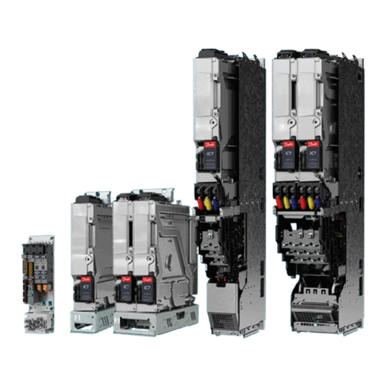
Danfoss iC7-Hybrid PROFINET Manuals
Manuals and User Guides for Danfoss iC7-Hybrid PROFINET. We have
7
Danfoss iC7-Hybrid PROFINET manuals available for free PDF download: Design Manual, Operating Manual, Installation Manual
Danfoss iC7-Hybrid PROFINET Design Manual (224 pages)
Liquid-cooled System Modules
Brand:
Danfoss
| Category:
Control Unit
| Size: 25 MB
Table of Contents
Table of Contents
3
Introduction
11
Purpose of this Design Guide
11
Additional Resources
11
Planning and Design Support Materials
11
Overview of Available Planning and Design Support Materials
11
Locating Support Information
12
Version History
12
Abbreviations
12
Recommended Disposal
13
Safety
14
Safety Symbols
14
General Safety Considerations
14
Target Group and Necessary Qualifications
15
Danfoss Ic7 Series
16
Overview of Ic7 Series
16
Overview of the Ic7 Series Liquid-Cooled System Modules
17
System Modules
17
Control System of the System Modules
19
Contents of the Delivery
20
Description of the Frame Designation
20
Weights
20
Common DC Bus Drive System
21
Description of the Model Code
22
Labels on the Products
23
Labels on the System Module
23
Labels on Other Components
24
Product Label
25
Lifting the Product
26
Lifting the System Modules
26
Lifting the System Modules with Integration Unit
26
Lifting the Filters
27
Mechanical Installation Considerations
28
Storing the System Module
28
Requirements for the Cabinet
28
Mechanical Installation
28
Installation Requirements
28
Installation Directions
28
Installing System Modules
28
Installing System Modules into a Cabinet Vertically
28
Installing System Modules into a Cabinet Horizontally
30
Installing System Modules into a Cabinet on Their Backsides
30
Installing System Modules with Integration Units
31
Installing System Modules with Integration Units into a Cabinet Vertically
31
Installing System Modules with Integration Units into a Cabinet Horizontally
33
Installing System Modules with Integration Units into a Cabinet on Their Backsides
34
Installing Filters
35
Installing L Filter into a Cabinet, 400 A, 1000 a
35
Installing L Filter into a Cabinet, 1640 a
35
Cooling Requirements
37
Safety in Liquid-Cooling
37
General Information on Cooling
37
Coolant
39
Quality Requirements for the Purified Water
39
Purified Water as Coolant
39
Antifreeze MIX as Coolant
39
Temperature of the Coolant
40
Cooling System
40
Materials
40
Heat Exchanger
41
Flow Rate of the Coolant
41
Flow Rates in Parallel Power Units
42
Volume of the Pipe
43
Pressure Drop and Correction Factors
44
Pressure Drop of IM10L, IM12L, AM10L, AM12L, DM10L and DM12L
45
Pressure Drop of AR10L, IR10L, and Filters
46
Pressure Drop of AR12L, IR12L, and Filters
48
Pressure Drop of the Grid-Side L Filter
50
Pressure Drop of DR10L, DR12L, and Filters
51
Cooling Circuit Connectors
52
Pipe Ferrules
53
Insertion of Pipes into Cooling Circuit Connectors
53
Inlet and Outlet Connectors of System Modules
54
Inlet and Outlet Connectors of System Modules with Integration Units
55
Inlet and Outlet Connectors of the L Filter
56
Cooling Circuit Pipes
56
Bending Pipes in the Air
57
Bending Pipes with a Bending Jig
58
Filling the Cooling System
59
Condensation
62
Air Cooling Requirements
62
Electrical Installation
65
Fuses of the Drive System
65
Guidelines for DC Connections of System Modules
65
Grounding Principles
67
Cable Requirements
67
Requirements for DC-Source Cables of DC/DC Converters
68
Prerequisites for Cable Installation
68
Recommended Installation of Motor Cables
70
Field Cabling Installation
71
Installation of Cables with the Power Terminal Adapter
71
Installing the DC Fuses to the DC Terminals
71
DC-Bus Connection Inductance
73
Auxiliary Power Connection, INU
73
Indicator Light Definitions
74
Installation in an IT System
75
Changing the EMC Protection Level, AR10L
77
Changing the EMC Protection Level, AR12L
78
Changing the EMC Protection Level, LC Filter, OF7Z1, 380 a
79
Changing the EMC Protection Level, LC Filter, OF7Z1, 760 a
80
Filters
81
Du/Dt Filter
81
Common-Mode Filter
83
LC Filter
85
DC Filter
85
Auxbus Communication
85
Usage of Auxbus
85
Auxbus Cable Requirements
87
Auxbus Grounding Principles
88
The Pre-Charging Unit
88
Derating
90
Derating of Switching Frequency, INU
90
Derating of Coolant Temperature
90
Derating of Voltage Imbalance, AFE/GC
90
Derating of DC-Bus Voltage
91
Modulator Types
91
Control Unit
93
Modular Control Unit
93
Control Board
94
Definitions of the Indicator Lights on the Control Board
95
Control Board Connections
96
Star Coupler Board
97
Definitions of the Indicator Lights on the Star Coupler Board
100
Star Coupler Board Connections
100
I/O and Relay Option Connections
101
I/O and Relay Option Interface
104
Analog Inputs
104
Analog Outputs
104
Digital Inputs
105
Digital Outputs
105
Relay Outputs
106
Analog Reference Voltage Output
107
DC Voltage Output
107
Thermistor Input
107
Assembling the Control Unit Mounting Plates
107
Attaching the Control Unit Mounting Plates
108
Installing the Control Unit
109
Installing Boards to the Modular Control Unit
109
Connecting the Fieldbus Cable and the Fiber Cables
110
Installing the Control Cables into the Control Terminals
111
Connecting the Control Panel
112
Fiber Cable Requirements
112
Maintenance
113
Preventive Maintenance Recommendations
113
Maintenance Log for Cooling System
116
Using the Product Modified Label
116
Replacing the RTC Battery
117
Removing the System Module from the Integration Unit
118
Installing the System Module in the Integration Unit
121
Draining the System Modules
123
Draining the System Modules, System Modules with Integration Units, and Filters
123
Draining the Power Units for Xr10L and Xr12L
124
Specifications
126
Tightening Torques
126
Dimensions
127
Dimensions of the Inverter Module, IM10L, AFE/GC Module, AM10L, and DC/DC Converter Module, DM10L
127
Dimensions of the Inverter Module, IR10L
128
Dimensions of the Active Front-End Module/Grid Converter, AR10L
129
Dimensions of the DC/DC Converter, DR10L
130
Dimensions of the Inverter Module, IM12L, AFE/GC Module, AM12L, and DC/DC Converter Module, DM12L
131
Dimensions of the Inverter Module, IR12L
132
Dimensions of Active Front-End Module/Grid Converter, AR12L
133
Dimensions of the DC/DC Converter, DR12L
134
Dimensions of the LC Filter for AM10L
135
Advertisement
Danfoss iC7-Hybrid PROFINET Operating Manual (82 pages)
Cooling Modules
Brand:
Danfoss
| Category:
Freezer
| Size: 6 MB
Table of Contents
Table of Contents
3
Introduction
7
Purpose of this Operating Guide
7
Additional Resources
7
Version History
7
Abbreviations
7
Disposal
8
Safety
9
Safety Symbols
9
General Safety Considerations
9
Target Group and Necessary Qualifications
9
Designated Use
10
Safe Operation
10
Product Overview
11
Product Variants
11
Description of the Model Code
11
Outer Dimensions and Weights
12
Receiving the Product
13
Checking the Shipment
13
Storing the Cooling Module
13
Lifting the Cooling Module
13
Mechanical Installation
16
Required Environmental Conditions
16
Installation Preparations
16
Installing the Standalone Cooling Module into the Cabinet
16
Installing the Standalone Cooling Module Without a Cabinet
19
Installing the Enclosed Cooling Module
20
Cooling Installation
22
Safety in Liquid-Cooling
22
The Operating Principle of the Cooling Module
22
Components of the Drive Circuit
23
Components of the External Circuit
24
Direction of Coolant Flow
25
Coolant Quality in the Drive Circuit
26
Quality Requirements for the Purified Water
26
Coolant Quality in the External Circuit
27
Purified Water as Coolant
27
Antifreeze MIX as Coolant
28
Materials
28
Pipe Connections
28
Connecting Pipes with Axilock Joints
30
Location of Valves and Instrumentation
30
Draining the Cooling System
33
Flushing the Pipes
33
Doing the Pressure Test
34
Filling the Cooling System
37
Filling the Cooling System by Progressive Circulation
37
Filling the Cooling System by Forced De-Airing
38
Checking the Pump Rotation Direction
39
Electrical Installation
41
Electrical Safety
41
Electrical Components
41
Control Unit (-AA1)
41
Main Switch (-QB0)
41
Fuses (-FC1)
41
Auxiliary Voltage Transformer (-TA4)
42
DC Power Supply (-TB7)
42
Service Switch (-SF3)
42
Pump Contactors (-QA5.1/-QA5.2)
43
Thermal Overload Relays (-FCX.1/-FCX.2)
43
Auxiliary Relays (-KFJ.1-3)
44
Liquid Heaters (-EBZ.1/-EBZ.2)
44
Cabinet Heater (-EB1)
44
Cable and Fuse Requirements
44
Installing the Mains Cables
44
Mains Connection Data
45
External Auxiliary Voltage Connection
45
Routing Control Wires to the Control Compartment
45
Instruments and Their Function
46
Pressure Transmitter (PT11 and PT12)
46
Temperature Sensor (TE11)
46
Liquid Level Sensor (LLS11)
46
Leakage Sensor (LS11)
47
Ambient Temperature/Humidity Sensor (TE21/ME21)
47
3-Way Valve Actuator (FV11)
47
Control Unit
48
Control Compartment Overview
48
Internal Components of the Control Compartment
50
Fieldbus Protocols
51
Starting the Cooling Module
52
Commissioning the Cooling Module
52
Maintenance
53
Preventive Maintenance Recommendations
53
Maintenance Log for Cooling System
55
Cleaning the Heat Exchanger
56
Specifications
57
Dimensions
57
Dimensions of the Single-Pump Standalone Cooling Module
57
Dimensions of the Dual-Pump Standalone Cooling Module
58
Dimensions of the Single-Pump Enclosed Cooling Module, Drive Circuit Pipes on the Left
59
Dimensions of the Dual-Pump Enclosed Cooling Module, Drive Circuit Pipes on the Left
60
Dimensions of the Single-Pump Enclosed Cooling Module, Drive Circuit Pipes on the Right
61
Dimensions of the Dual-Pump Enclosed Cooling Module, Drive Circuit Pipes on the Right
62
Dimensions of the Optional DIN Flanges
63
Dimensions of the Optional ANSI Flanges
64
Options
64
Supply Pressure
66
Supply Pressure of the 152 Kw Single-Pump Cooling Module
66
Supply Pressure of the 152 Kw Dual-Pump Cooling Module
67
P & I Diagrams
68
Piping and Instrumentation Diagram of the Single-Pump Cooling Module with an External Heat Exchanger
68
Piping and Instrumentation Diagram of the Single-Pump Cooling Module
69
Piping and Instrumentation Diagram of the Dual-Pump Cooling Module
70
Wiring Diagrams
71
Signal and Power Block Diagrams
76
Mains Connections
77
Cooling Characteristics
78
Liquid-Cooling Specifications
78
Environmental Conditions
79
Danfoss iC7-Hybrid PROFINET Operating Manual (32 pages)
Brand:
Danfoss
| Category:
Industrial Equipment
| Size: 4 MB
Table of Contents
Table of Contents
3
1 Introduction and Safety
5
Purpose of the Operating Guide
5
Additional Resources
5
Safety Symbols
5
Qualified Personnel
6
Safety Precautions
6
Abbreviations
7
Trademarks
8
Version History
8
2 Product Overview
10
PROFINET Features and Technical Data
10
Communication Profiles and Objects
10
Ic7 Hybrid Profile
11
Overview
11
Control Word
11
Status Word
12
Submodules
13
Functional Extension Options
14
Network Topologies
14
Overview
14
Line Topology
14
Star Topology
15
Ring Topology
16
3 Fieldbus Cable Connections
18
Prerequisites for Installation
18
Communication Interface X1/X2 in Frames FA02-FA12
18
Communication Interface X1/X2 in Frames FK06-FK12
18
Communication Interface X1/X2 in System Modules
19
EMC-Compliant Installation
20
Overview
20
Grounding
20
Cable Routing
21
4 Configuration
22
Configuring the Ethernet Interface
22
Configuring Name of Station
22
GSDML File (Device Description File)
23
Reference and Main Actual Handling
23
Connectivity Settings
23
5 Parameter Access
25
Overview
25
Profidrive Parameter Numbers
25
6 Troubleshooting
26
Diagnostics
26
PROFINET Report
26
Configuring Port Mirroring Settings
27
Identifying a Unit
27
Fieldbus Indicator Leds
28
Advertisement
Danfoss iC7-Hybrid PROFINET Installation Manual (22 pages)
Liquid-cooled DC Filter
Brand:
Danfoss
| Category:
Water Filtration Systems
| Size: 1 MB
Table of Contents
Mechanical Installation
2
Cooling Requirements
5
Electrical Installation Safety
8
Cable Requirements
8
Installing the Cables
10
Wiring Diagrams
17
Maintenance
18
Danfoss iC7-Hybrid PROFINET Installation Manual (21 pages)
Liquid-cooled LC Filter
Brand:
Danfoss
| Category:
Water Filtration Systems
| Size: 1 MB
Table of Contents
Mechanical Installation
2
Cooling Requirements
5
Electrical Installation Safety
8
Cable Requirements
8
Installing the Cables
9
Wiring Diagrams
16
Maintenance
17
Danfoss iC7-Hybrid PROFINET Installation Manual (21 pages)
Liquid-cooled L Filter
Brand:
Danfoss
| Category:
Water Filtration Systems
| Size: 1 MB
Table of Contents
Mechanical Installation
2
Cooling Requirements
8
Electrical Installation Safety
11
Cable Requirements
12
Installing the Cables
12
Wiring Diagrams
15
Maintenance
16
Danfoss iC7-Hybrid PROFINET Installation Manual (20 pages)
Liquid-cooled dU/dt Filter
Brand:
Danfoss
| Category:
Water Filtration Systems
| Size: 2 MB
Table of Contents
Mechanical Installation
2
Cooling Requirements
6
Electrical Installation
9
Wiring Diagrams
16
Maintenance
17
Advertisement
Related Products
Danfoss iC7-Hybrid Modbus
Danfoss IPS 8
Danfoss iC7-BAIP
Danfoss iC7-Marine PROFINET
Danfoss iSave 21 Plus
Danfoss iC7-Hybrid7 Series
Danfoss iC7-60EA3A05-385A
Danfoss iC7-60SLIN07-3260E00F Series
Danfoss iC7-60SLxx07-3600E00F Series
Danfoss iC7-60SLxx07-5400E00F Series
Danfoss Categories
Controller
DC Drives
Thermostat
Control Unit
Air Compressor
More Danfoss Manuals
Login
Sign In
OR
Sign in with Facebook
Sign in with Google
Upload manual
Upload from disk
Upload from URL