Sign In
Upload
Manuals
Brands
Danfoss Manuals
Industrial Equipment
iC7-Marine PROFINET
Danfoss iC7-Marine PROFINET Manuals
Manuals and User Guides for Danfoss iC7-Marine PROFINET. We have
2
Danfoss iC7-Marine PROFINET manuals available for free PDF download: Design Manual, Operating Manual
Danfoss iC7-Marine PROFINET Design Manual (224 pages)
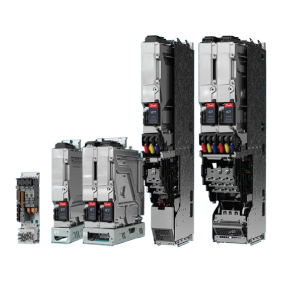
Liquid-cooled System Modules
Brand:
Danfoss
| Category:
Control Unit
| Size: 25 MB
Table of Contents
Table of Contents
3
Introduction
11
Purpose of this Design Guide
11
Additional Resources
11
Planning and Design Support Materials
11
Overview of Available Planning and Design Support Materials
11
Locating Support Information
12
Version History
12
Abbreviations
12
Recommended Disposal
13
Safety
14
Safety Symbols
14
General Safety Considerations
14
Target Group and Necessary Qualifications
15
Danfoss Ic7 Series
16
Overview of Ic7 Series
16
Overview of the Ic7 Series Liquid-Cooled System Modules
17
System Modules
17
Control System of the System Modules
19
Contents of the Delivery
20
Description of the Frame Designation
20
Weights
20
Common DC Bus Drive System
21
Description of the Model Code
22
Labels on the Products
23
Labels on the System Module
23
Labels on Other Components
24
Product Label
25
Lifting the Product
26
Lifting the System Modules
26
Lifting the System Modules with Integration Unit
26
Lifting the Filters
27
Mechanical Installation Considerations
28
Storing the System Module
28
Requirements for the Cabinet
28
Mechanical Installation
28
Installation Requirements
28
Installation Directions
28
Installing System Modules
28
Installing System Modules into a Cabinet Vertically
28
Installing System Modules into a Cabinet Horizontally
30
Installing System Modules into a Cabinet on Their Backsides
30
Installing System Modules with Integration Units
31
Installing System Modules with Integration Units into a Cabinet Vertically
31
Installing System Modules with Integration Units into a Cabinet Horizontally
33
Installing System Modules with Integration Units into a Cabinet on Their Backsides
34
Installing Filters
35
Installing L Filter into a Cabinet, 400 A, 1000 a
35
Installing L Filter into a Cabinet, 1640 a
35
Cooling Requirements
37
Safety in Liquid-Cooling
37
General Information on Cooling
37
Coolant
39
Quality Requirements for the Purified Water
39
Purified Water as Coolant
39
Antifreeze MIX as Coolant
39
Temperature of the Coolant
40
Cooling System
40
Materials
40
Heat Exchanger
41
Flow Rate of the Coolant
41
Flow Rates in Parallel Power Units
42
Volume of the Pipe
43
Pressure Drop and Correction Factors
44
Pressure Drop of IM10L, IM12L, AM10L, AM12L, DM10L and DM12L
45
Pressure Drop of AR10L, IR10L, and Filters
46
Pressure Drop of AR12L, IR12L, and Filters
48
Pressure Drop of the Grid-Side L Filter
50
Pressure Drop of DR10L, DR12L, and Filters
51
Cooling Circuit Connectors
52
Pipe Ferrules
53
Insertion of Pipes into Cooling Circuit Connectors
53
Inlet and Outlet Connectors of System Modules
54
Inlet and Outlet Connectors of System Modules with Integration Units
55
Inlet and Outlet Connectors of the L Filter
56
Cooling Circuit Pipes
56
Bending Pipes in the Air
57
Bending Pipes with a Bending Jig
58
Filling the Cooling System
59
Condensation
62
Air Cooling Requirements
62
Electrical Installation
65
Fuses of the Drive System
65
Guidelines for DC Connections of System Modules
65
Grounding Principles
67
Cable Requirements
67
Requirements for DC-Source Cables of DC/DC Converters
68
Prerequisites for Cable Installation
68
Recommended Installation of Motor Cables
70
Field Cabling Installation
71
Installation of Cables with the Power Terminal Adapter
71
Installing the DC Fuses to the DC Terminals
71
DC-Bus Connection Inductance
73
Auxiliary Power Connection, INU
73
Indicator Light Definitions
74
Installation in an IT System
75
Changing the EMC Protection Level, AR10L
77
Changing the EMC Protection Level, AR12L
78
Changing the EMC Protection Level, LC Filter, OF7Z1, 380 a
79
Changing the EMC Protection Level, LC Filter, OF7Z1, 760 a
80
Filters
81
Du/Dt Filter
81
Common-Mode Filter
83
LC Filter
85
DC Filter
85
Auxbus Communication
85
Usage of Auxbus
85
Auxbus Cable Requirements
87
Auxbus Grounding Principles
88
The Pre-Charging Unit
88
Derating
90
Derating of Switching Frequency, INU
90
Derating of Coolant Temperature
90
Derating of Voltage Imbalance, AFE/GC
90
Derating of DC-Bus Voltage
91
Modulator Types
91
Control Unit
93
Modular Control Unit
93
Control Board
94
Definitions of the Indicator Lights on the Control Board
95
Control Board Connections
96
Star Coupler Board
97
Definitions of the Indicator Lights on the Star Coupler Board
100
Star Coupler Board Connections
100
I/O and Relay Option Connections
101
I/O and Relay Option Interface
104
Analog Inputs
104
Analog Outputs
104
Digital Inputs
105
Digital Outputs
105
Relay Outputs
106
Analog Reference Voltage Output
107
DC Voltage Output
107
Thermistor Input
107
Assembling the Control Unit Mounting Plates
107
Attaching the Control Unit Mounting Plates
108
Installing the Control Unit
109
Installing Boards to the Modular Control Unit
109
Connecting the Fieldbus Cable and the Fiber Cables
110
Installing the Control Cables into the Control Terminals
111
Connecting the Control Panel
112
Fiber Cable Requirements
112
Maintenance
113
Preventive Maintenance Recommendations
113
Maintenance Log for Cooling System
116
Using the Product Modified Label
116
Replacing the RTC Battery
117
Removing the System Module from the Integration Unit
118
Installing the System Module in the Integration Unit
121
Draining the System Modules
123
Draining the System Modules, System Modules with Integration Units, and Filters
123
Draining the Power Units for Xr10L and Xr12L
124
Specifications
126
Tightening Torques
126
Dimensions
127
Dimensions of the Inverter Module, IM10L, AFE/GC Module, AM10L, and DC/DC Converter Module, DM10L
127
Dimensions of the Inverter Module, IR10L
128
Dimensions of the Active Front-End Module/Grid Converter, AR10L
129
Dimensions of the DC/DC Converter, DR10L
130
Dimensions of the Inverter Module, IM12L, AFE/GC Module, AM12L, and DC/DC Converter Module, DM12L
131
Dimensions of the Inverter Module, IR12L
132
Dimensions of Active Front-End Module/Grid Converter, AR12L
133
Dimensions of the DC/DC Converter, DR12L
134
Dimensions of the LC Filter for AM10L
135
Advertisement
Danfoss iC7-Marine PROFINET Operating Manual (42 pages)
PROFINET RT
Brand:
Danfoss
| Category:
Industrial Equipment
| Size: 3 MB
Table of Contents
Table of Contents
3
Introduction and Safety
5
Purpose of the Operating Guide
5
Additional Resources
5
Safety Symbols
5
Qualified Personnel
6
Safety Precautions
6
Abbreviations
7
Trademarks
8
Version History
8
Product Overview
10
PROFINET Features and Technical Data
10
Communication Profiles and Objects
10
IC Speed Profile
11
Overview
11
Control Word (CTW)
11
Status Word (STW)
12
Profidrive - Standard Telegram
13
Overview
13
Control Word (CTW)
13
Status Word (STW)
15
Profidrive State Machine
16
IC Active Front End Profile
16
Overview
16
Control Word (CTW)
17
Status Word
18
Submodules
19
Functional Extension Options
19
Network Topologies
20
Overview
20
Line Topology
20
Star Topology
21
Ring Topology
22
Fieldbus Cable Connections
24
Prerequisites for Installation
24
Communication Interface X1/X2 in Frames FA02-FA12
24
Communication Interface X1/X2 in Frames FK06-FK12
24
Communication Interface X1/X2 in System Modules
25
EMC-Compliant Installation
26
Overview
26
Grounding
26
Cable Routing
27
Configuration
28
Configuring the Ethernet Interface
28
Configuring Name of Station
28
GSDML File (Device Description File)
29
Reference and Main Actual Handling
29
Propulsion & Machinery Application
29
Active Front End Application
30
General Connectivity Settings
31
Propulsion & Machinery Application Connectivity Settings
31
Active Front End Application Connectivity Settings
33
Parameter Access
35
Overview
35
Profidrive Parameter Numbers
35
Troubleshooting
36
Diagnostics
36
PROFINET Report
36
Configuring Port Mirroring Settings
37
Identifying a Unit
37
Fieldbus Indicator Leds
38
Advertisement
Related Products
Danfoss IPS 8
Danfoss iC7-BAIP
Danfoss iC7-Hybrid PROFINET
Danfoss iSave 21 Plus
Danfoss iC7-Hybrid Modbus
Danfoss iC7-Marine Series
Danfoss iC7-60SAIN05-730A
Danfoss iC7-60SAIN05-1760
Danfoss iC7-60SLIN07-2460E00F Series
Danfoss iC7-60SLDC07-1200
Danfoss Categories
Controller
DC Drives
Thermostat
Control Unit
Air Compressor
More Danfoss Manuals
Login
Sign In
OR
Sign in with Facebook
Sign in with Google
Upload manual
Upload from disk
Upload from URL