
Related Manuals for Pressura RPM10

Summary of Contents for Pressura RPM10
- Page 1 PRESSURA™ ROOM PRESSURE MONITOR MODEL RPM10 AND RPM20 OPERATION AND SERVICE MANUAL P/N 6006644, REVISION C JANUARY 2015...
- Page 3 PRESSURA™ ROOM PRESSURE CONTROLLER MODEL RPM10 AND RPM20 OPERATION AND SERVICE MANUAL P/N 6006644, REVISION C JANUARY 2015 U.S. AND CANADA OTHER COUNTRIES Sales & Customer Service: Sales & Customer Service: (800) 874-2811/(651) 490-2811 (001 651) 490-2811 Fax: Fax: (651) 490-3824...
- Page 5 Copyright TSI Incorporated / 2013-2015 / All rights reserved. Part number 6006644 / January 2015 Limitation of Warranty and Liability (effective April 2014) (For country-specific terms and conditions outside of the USA, please visit www.tsi.com.) Seller warrants the goods, excluding software, sold hereunder, under normal use and service as described in the operator's manual, to be free from defects in workmanship and material for 24 months, or if less, the length of time specified in the operator's manual, from the date of shipment to the customer.
- Page 6 TSI's Customer Service department at (800) 874- 2811 or (651) 490-2811. Trademarks TSI and TSI logo are registered trademarks of TSI Incorporated. PresSura is a trademark of TSI Incorporated. BACnet is a trademark of ASHRAE. Modbus is a registered trademark of Modicon, Inc. ®...
-
Page 7: Table Of Contents
CONTENTS HOW TO USE THIS MANUAL ...................... 1 Safety Information ....................1 Description of Caution Symbol ................1 Access Code / Passcode .................. 1 PART ONE ............................. 3 User Basics ......................3 The Instrument ..................... 3 Useful User Information ..................3 Operator Panel ..................... -
Page 8: Table Of Contents
Modbus Communications ................. 73 Unique to TSI ....................73 Network Points RAM Variables ............... 74 XRAM Variables ....................75 RPM10 Variable List ..................75 RPM20 Variable List ..................77 RPM20 Variable List ..................80 RPM20 Variable List ..................81 ®... -
Page 9: Safety Information
Refer to the Installation Instructions if there is any question as to whether the monitor has been installed properly. Safety Information This section gives instructions to promote safe and proper handling of Model RPM10 and RPM20 Room Monitors. There are no user-serviceable parts inside the instrument. Opening the instrument case will void the warranty. - Page 10 (This page intentionally left blank)
-
Page 11: Part One
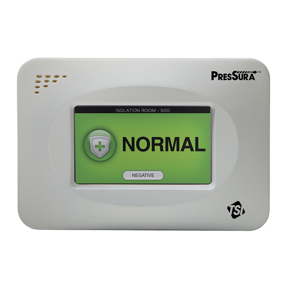
Operator Panel The Model RPM10 and RPM20 Room Monitors are easy to use. Normal vs. alarm condition and room modes are always shown on the display. In addition, the displayed can be configured to show the room pressure differential or all measurements. -
Page 12: Display Screen
Model RPM10 and RPM20 will not alarm. Operator Keys The following keys appear on the display of the Model RPM10 and RPM20 room monitor: MUTE key The MUTE key silences an audible alarm. The alarm remains silent until the MUTE TIME value has been reached or the unit returns to control set point. -
Page 13: Usb Port
Figure 3. USB Port Location Alarms The Model RPM10 and RPM20 monitors have visual (red light) and audible alarms to inform you of changing room conditions. The alarm levels (set points) are determined by facilities staff, which could be Engineering, Industrial Hygiene, or a facilities group depending on how the safety staff is organized. -
Page 14: Alarm Relays
ALARM RESET). Alarm Relays The PresSura monitors feature 2 alarm relays. The alarm relays can be field configured to either open or close to indicate an alarm condition, although they will close on loss of power. Relay 1 functions as the low alarm relay, and will activate after the alarm delay for low pressure, low flow, low temperature and low RH alarms. -
Page 15: Part Two
Part Two Technical Section The PresSura™ Room Pressure Monitor is ready to use after being properly installed and configured. The TSI through-the-wall sensor is factory calibrated, as are most pressure transducers. Figure 4 shows the Digital Interface Module (DIM) which is programmed with a default configuration that can be easily modified to fit your application. -
Page 16: Software Programming
2. Select the desired room mode by pressing on the desired room mode button at the bottom of the screen. NOTE: If a room mode is not selected, the PresSura monitor will return to the main running screen after a short delay, Figure 6. -
Page 17: Entering Menus
Refer to the Menu and Menu Items section for a list of the menus and their associated items. Entering Data After entering a menu item, the Model RPM10/RPM20 monitor display will change to select items. Some items have pre-defined choices selected through a drop-down menu; others allow numeric setpoints. - Page 18 Figure 9. Using a Drop-Down Selection Numeric Setpoints It is easy to enter new numeric setpoints on the PresSura Model RPM10/RPM20 monitor. On a numeric setpoint screen, the current setpoint is displayed in a box at the top left of the screen.
-
Page 19: Programming Example
Programming Example The following example demonstrates the keystroke sequence. In this example the negative low alarm set point for Room 1 will be changed from -0.01000 in H O to -0.01300 in H Unit is in normal operation. Swipe from the top right corner to the bottom left corner to access the menu system. -
Page 20: Menu And Menu Items
The menu items are always grouped by menu and then listed in menu item order, not alphabetical order. Figure 11 and Figure 12 show the PresSura Model RPM10 and RPM20 monitor menu items. Part Two... - Page 21 AO3 Sig Type Input 4 Configure Input 5 Configure Input 6 Configure Input 7 Configure See menu for items. See menu for items. See menu for items. See menu for items. Figure 11. Menu Items – Model RPM10 Monitor Technical Section...
- Page 22 Configure Rm1 Alarm AnteRm Alarm Rm2 Alarm # of Rooms Room Mode Room Mode Room Mode Rm1 Label Neg Low Alm Neg Low Alm Neg Low Alm AnteRm Label Neg Hi Alm Neg Hi Alm Neg Hi Alm Rm2 Label Pos Low Alm Pos Low Alm Pos Low Alm...
- Page 23 Number of Rooms # of Rooms The # of Rooms item selects the number of rooms the 1 Room RPM10: 1 Room Monitored Model RPM10 and RPM20 monitor will monitor and RPM20: 1 Room, control. RPM10 and 1 Room with RPM20...
- Page 24 Displayed Room Pressure, All be presented on the display during normal operating mode. Use the Units item to choose the units of measure: RPM10 and RPM20 ROOM STATUS displays the room mode as negative, positive or no isolation. ROOM PRESSURE displays the room mode and the current measurement of room pressure differential.
- Page 25 The Input 2 item is only active if the # of Rooms item is set to 1 ROOM WITH ANTEROOM. The Input 2 item is not functional on the Model RPM10 Monitor. It is only active on the Model RPM20 Monitor.
- Page 26 Go to the Input 6 menu to adjust parameters such as Occupancy Sensor, sensor range associated with Input6. Room 2 Door Switch The Input 6 item is not functional on the Model RPM10 Monitor. It is only active on the Model RPM20 Monitor. Configure INPUT7 Input 7 None The Input 7 item selects the desired input type for Input7.
- Page 27 Room Mode (pass code) is required to enter the menu items. The Menus Passcode item prevents unauthorized access to a menu. RPM10 and If the Passcode item is: RPM20 no code is required to enter the room mode or menu screens.
- Page 28 The Neg Low Alm item sets the negative low pressure Low Alarm +0.19500 in H alarm setpoint. A low alarm condition is defined as when the magnitude of the room pressure falls below the Neg RPM10 and Note: Neg Low Alm Low Alm setpoint. RPM20 cannot be set...
- Page 29 Exhaust Flow alarm setpoint. A minimum flow alarm is defined as when Alarm the exhaust flow is less than the Exh Low Alm setpoint. RPM10 and RPM20 Room 1 Low Sup Low Alm The Sup Low Alm item sets the minimum supply flow...
- Page 30 Calculation EXHAUST SUPPLY is normally used for positive rooms EXHAUST is normally used for negative rooms RPM10 and is used if the ACH calculation is not RPM20 desired Room Volume Room1 Vol The Room1 Vol item sets the room volume for the ACH...
- Page 31 AnteRm Alarm Menu SOFTWARE MENU ITEM ITEM DESCRIPTION ITEM RANGE DEFAULT VALUE NAME Anteroom Negative Neg Hi Alm The Neg Hi Alm item sets the negative high pressure -0.19500 in H O to -0.10000 in H High Alarm alarm setpoint. A high alarm condition is defined as when +0.19500 in H the room is more negative than the Neg Hi Alm setpoint.
- Page 32 Rm2 Alarm Menu SOFTWARE MENU ITEM ITEM DESCRIPTION ITEM RANGE DEFAULT VALUE NAME Positive Mode of Room 2 Room Mode The Room Mode item selects the room pressure Negative Negative direction. This item enables all related alarms, for RPM20 Room1 pressure direction selected.
-
Page 33: Alarm Constraints
In no isolation mode all alarms are turned off. 2. The PresSura monitor is programmed with deadbands between alarm setpoints to prevent the controller from cycling between high and low alarms due to normal fluctuations. Setpoint deadbands are: ... - Page 34 7. The display can only show one alarm message. Therefore, the monitor has an alarm priority system, with the highest priority alarm being displayed. If multiple alarms exist, the lower priority alarms will not display until after the highest priority alarm has been eliminated. The alarm priority is as follows: Room 1 pressure sensor –...
- Page 35 The Alarm Reset item selects how the alarms terminate Latched, Unlatched Unlatched after the unit returns to control set point. The Alarm Reset RPM10 and affects the audible alarm, visual alarm, and relay output, RPM20 which means all are latched or unlatched.
- Page 36 Signal used with Relay 2. If set to: Positive Room RPM10 and HIGH ALARM the PresSura monitor will activate the relay RPM20 if a high alarm condition exists. NEGATIVE ROOM the PresSura monitor will activate the relay when the mode for Room 1 is Negative.
- Page 37 BACnet communications. Baud Rate Baud Rate The Baud Rate item sets the communication speed of the Modbus: 9600 Modbus: 9600 PresSura monitor when using Modbus or BACnet BACnet: 9600, BACnet: RPM10 and communications. 19200, 38400, AutoBaud...
- Page 38 Nurse’s Station Monitor. Each unit on the network must RPM10 and have its own unique address. RPM20 NOTE: PresSura Model RPM10 and RPM20 monitors will have rooms displayed on the Nurse’s Station Monitor in order of the Nurse Address. The PresSura monitor with the lowest Nurse Address will be displayed at the top-left of the Nurse’s...
- Page 39 The AO1 Sig Type item selects the measurement that the None None Signal Type Type analog output signal will represent. RPM10 and RPM20 Analog Output AO2 Sig The AO2 Sig Type item selects the measurement that the Room 1 Pressure...
- Page 40 Interface Menu SOFTWARE DEFAULT MENU ITEM ITEM DESCRIPTION ITEM RANGE NAME VALUE Analog Output AO3 Sig The AO3 Sig Type item selects the measurement that the Room 2 Pressure None Signal Type Type analog output signal will represent. Supply Flow Exhaust Flow RPM20 None...
- Page 41 The Touch Cal item starts the touchscreen recalibration process. While recalibrating the touchscreen, Touchscreen the PresSura monitor will direct the user to touch the screen in various places. RPM10 and NOTE: Recalibrating the touchscreen is best accomplished using a stylus, pen, or similar object.
- Page 42 The Sensor Span item is used to match or calibrate the Set Sensor Span Sensor Span None Unit is factory PresSura TSI sensor to the average room pressure velocity Calibration calibrated and as measured by a portable air velocity meter. should not need RPM10 and adjustment.
- Page 43 Check Status The Check Status item is used to check the communication None Status status of the sensor. After pressing the button, the PresSura unit will respond with: COMM ERROR - DIM cannot communicate with sensor. Check all wiring and the pressure sensor address.
- Page 44 0 to 5 V Sensor Voltage signal when a pressure transducer is used to measure Output room pressure differential. RPM10 and RPM20 Set Maximum Signal Max The Signal Max item is used to set the maximum output 1 to 10 V...
- Page 45 Sensor Span The Sensor Span item is used to match or calibrate the None Unit is factory Calibration PresSura monitor TSI sensor to the average room pressure calibrated and velocity as measured by a portable air velocity meter. should not RPM20 need adjustment.
- Page 46 The Check Status item is used to check the None Status communication status of the sensor. After pressing the button, the PresSura unit will respond with: RPM20 COMM ERROR - DIM cannot communicate with sensor. Check all wiring and the pressure sensor address.
- Page 47 Input2 Config Menu Press Trans SOFTWARE DEFAULT MENU ITEM ITEM DESCRIPTION ITEM RANGE NAME VALUE Set Minimum Sensor Min The Sensor Min item is used to set the minimum reading -1.00 to + 1.00 in H Sensor Pressure of a pressure transducer used to measure room pressure Output differential.
- Page 48 W A R N IN G If the proper Duct Area is not programmed into the Model RPM10 and RPM20, the flow measurement will be incorrect. Thus, all the other information that uses the flow measurement, such as the flow alarms, will also be incorrect.
- Page 49 Sensor Zero The Sensor Zero item is used to re-zero the pressure NONE Zero Calibration transducer zero calibration point. RPM10 and RPM20 Set Maximum Sensor Max The Sensor Max item is used to set the maximum reading 0 to 1.00 in H 1.00 in H...
- Page 50 The Reset Cal item is used to return to the factory default None calibration, undoing any field calibration adjustments. RPM10 and When this menu item is entered, the controller will prompt RPM20 the user to verify that they want to do this by displaying the message “Reset Settings to Factory Default?”...
- Page 51 W A R N IN G If the proper Duct Area is not programmed into the Model RPM10 and RPM20, the flow measurement will be incorrect. Thus, all the other information that uses the flow measurement, such as the flow alarms, will also be incorrect.
- Page 52 0 to 10,000 fpm Sensor Output of a flow station used to measure supply air flow. The Sensor Max item has increments of 1000 fpm. RPM10 and RPM20 Set Minimum Signal Min The Signal Min item is used to set the minimum output...
- Page 53 The Min Flow item sets the flow rate through the venturi 0 to 10000 cfm 0 cfm valve when it is fully closed. The display will indicate a RPM10 and volumetric flow rate. Adjust the displayed value to match RPM20 the flow through the venturi valve.
- Page 54 ITEM DESCRIPTION ITEM RANGE NAME VALUE Low Flow Alarm Low Flow Sig The Low Flow Sig item sets the signal the Model RPM10 Open, Closed Closed Signal or RPM20 Room Pressure Monitor will receive to indicate a low supply flow condition.
- Page 55 While this number can be entered in increments of 1 foot, the density adjustments are in 1,000 foot increments. For example, if the PresSura will interpret Elevation settings between 0 and 999 feet as 0 feet, settings between 1000 and 1999 feet as 1000 feet, etc.
- Page 56 Input3 Config Menu Press Trans SOFTWARE DEFAULT MENU ITEM ITEM DESCRIPTION ITEM RANGE NAME VALUE Set Minimum Sensor Min The Sensor Min item is used to set the minimum reading -1.00 to + 1.00 in H Sensor Pressure of a pressure transducer used to measure room pressure Output differential.
- Page 57 RPM10 and RPM20 Input5 Config Menu Rm1 Key Switch ITEM DESCRIPTION The Model RPM10 or RPM20 will display a message “Nothing to Configure” when Input 5 is set to Rm1 Key Switch and the user enters the Input5 Config menu.
- Page 58 Input5 Config Menu SOFTWARE DEFAULT MENU ITEM ITEM DESCRIPTION ITEM RANGE NAME VALUE Set Minimum Sensor Min The Sensor Min item is used to set the minimum reading 0 to 100% RH 0% RH Sensor Output of the relative humidity sensor. RPM20 Set Maximum Sensor Max...
- Page 59 Input6 Config Menu Rm1 Temp SOFTWARE DEFAULT MENU ITEM ITEM DESCRIPTION ITEM RANGE NAME VALUE Adjust Sensor Sensor Span The Sensor Span item is used to adjust the calibration of -10F to +10°F 0°F Calibration the temperature sensor. RPM20 Reset Calibration Reset Cal The Reset Cal item is used to return to the factory default None...
- Page 60 W A R N IN G If the proper Duct Area is not programmed into the Model RPM10 and RPM20, the flow measurement will be incorrect. Thus, all the other information that uses the flow measurement, such as the flow alarms, will also be incorrect.
- Page 61 For example, if the pressure transducer has a range of 0 in H O to +0.25 in H O 0 to +62.5 Pa), the RPM10 and Sensor Max should be set to +0.25 in H O (+62.5 Pa). RPM20...
- Page 62 The Reset Cal item is used to return to the factory default None calibration, undoing any field calibration adjustments. RPM10 and When this menu item is entered, the controller will prompt RPM20 the user to verify that they want to do this by displaying the message “Reset Settings to Factory Default?”...
- Page 63 W A R N IN G If the proper Duct Area is not programmed into the Model RPM10 and RPM20, the flow measurement will be incorrect. Thus, all the other information that uses the flow measurement, such as the flow alarms, will also be incorrect.
- Page 64 0 to 10,000 fpm Sensor Output of a flow station used to measure exhaust air flow. The Sensor Max item has increments of 1000 fpm. RPM10 and RPM20 Set Minimum Signal Min The Signal Min item is used to set the minimum output...
- Page 65 The Min Flow item sets the flow rate through the venturi 0 to 10000 cfm 0 cfm valve when it is fully closed. The display will indicate a RPM10 and volumetric flow rate. Adjust the displayed value to match RPM20 the flow through the venturi valve.
- Page 66 ITEM DESCRIPTION ITEM RANGE NAME VALUE Low Flow alarm Low Flow Sig The Low Flow Sig item sets the signal the Model RPM10 Open, Closed Close Signal and RPM20 Room Pressure Controller will receive to indicate a low exhaust flow condition.
-
Page 67: Room Pressure Calibration
4. Save the reading and exit the menu system. Pressure Transducer Calibration NOTE: This calibration process is to configure the PresSura monitor to match the reading from the pressure transducer. If the pressure transducer itself needs to be calibrated, refer to the instructions that come with the pressure transducer. -
Page 68: Flow Calibration
Remove the tubing from the high and low ports of the transducer. c. Enter the PRESSURE ZERO item on the PresSura monitor. d. Reconnect tubing to the high and low ports of the pressure transducer, using the mark to connect the high pressure tubing to the high port. - Page 69 g. The low flow calibration is complete. 4. Enter the HIGH CAL item to perform the high flow calibration submenu with the following items: VOLTAGE INPUT Current voltage from pressure transducer Current flow rate UNCALIBRATED FLOW ZERO VOLTAGE Voltage from pressure transducer during Flow Station Pressure Transducer Zero CALIBRATED FLOW Input actual flow as measured with reference instrument here...
- Page 70 Supply/Exhaust Switch Calibration NOTE: Flow switches are optional and may not be installed in your system. Flow switches do not actually measure the flow, but are designed to provide an open or closed signal to indicate the presence or absence of flow.
-
Page 71: Maintenance And Repair Parts
The Model RPM10 and RPM20 PresSura Room Pressure Monitors require minimal maintenance. Periodic inspections of system components as well as an occasional pressure sensor cleaning are all that are needed to ensure that the PresSura monitor is operating properly. System Component Inspection It is recommended that the pressure sensor be periodically inspected for accumulation of contaminants. -
Page 72: Replacement Parts
WARNING If you are using a liquid to clean the sensor, turn off power to the RPM10 / RPM20 PresSura Monitor. Do not use compressed air to clean the velocity sensors. -
Page 73: Hardware Test
Software and hardware problems are covered in the troubleshooting chart. Pick the problem that most closely resembles your problem and review the possible symptoms and corrective action. Software or system performance problems can and are affected by the supply air system, exhaust air system, or physical configuration of the room. - Page 74 Enter the View Inputs item to view all inputs with real-time updates. Figure 16. View Inputs screen in Diagnostics menu The Model RPM10/RPM20 monitor will display “Unconfigured” for any inputs that have not been configured. Go to the Configure menu to configure these inputs appropriately.
-
Page 75: Troubleshooting Chart
Test - View Outputs Enter the View Outputs item to view all output signals with real-time updates. Figure 17. View Outputs screen in Diagnostics menu If the monitor passes each of the tests, the mechanical piece parts are all functioning correctly. Troubleshooting Chart Symptom Possible Cause... - Page 76 Symptom Possible Cause Corrective Action Sensor does not Incorrect Rm1 pressure sensor must have address of 1. Anteroom calibrate. pressure sensor sensor must have address of 2. Rm2 sensor must have address. address of 3. Check pressure sensor DIP switches 5 & 6 and verify address is correct (7 to 12 must be OFF).
- Page 77 SELECT key. Return to the LON item, monitor. select the SERVICE PIN option and press the SELECT key. ® Selecting GO UNCONFIG will reset the PresSura monitor’s (LonWorks only) authentication key, allowing the SERVICE PIN to install or ®...
- Page 78 Symptom Possible Cause Corrective Action Alarm relays do Alarms are Enter the Rm1 Alarm, AnteRm Alarm or Rm2 Alarm menu. not work. turned off. Verify that the Alarm Enable item is set to enable the high or low alarms as desired. Incorrect wiring.
-
Page 79: Specifications
Appendix A Specifications* Digital Interface Module Display Range ........-0.20000 to +0.20000 in H O (-50 to +50 Pa): TSI Sensor -1.00 to +1.00 in H O (-250 to +250 Pa): Pressure Transducer Resolution ......... 5% of reading or 0.00001 in H O (0.0025 Pa): TSI Sensor 5% of reading or 0.001 in H O (0.25 Pa): Pressure... - Page 80 Outputs–Three (3)Total Output 1 ........None Output 2 ........Room 1 Pressure Out, Exhaust Flow Out (0 to 10 VDC / 4-20 mA) Output 3 ........Room 2 Pressure Out, Exhaust Flow Out, Supply Flow Out (0 to 10 VDC / 4-20 mA) Alarm Contacts ......
-
Page 81: Appendix B
PresSura room monitors functions. This information is not useful to the DDC system and is therefore deleted. Skipping numbers in the sequence will not cause any communication problems. If a variable is not used by the particular PresSura room monitors, it will be reported with a value of -1. -
Page 82: Network Points Ram Variables
Network Points RAM Variables RAM variables use the Modbus command 04 Read Input Registers. RAM variables are read only variables that correspond to what is shown on Digital Interface Module (DIM) display. TSI offers a number of different models, so if a feature is not available on a unit, the variable is set to 0. Variable Information Provided to Master Variable Name... -
Page 83: Xram Variables
“menu items” that are configured from the monitor keypad. The calibration and control items are not accessible from the DDC system. This is for safety reasons since each room is individually setup for maximum performance. RPM10 Variable List Variable Variable Name... - Page 84 RPM10 Variable List Variable Variable Name Address Read/Write Integer DDC system receives Input 7 Read Exhaust Pressure Flow Configuration Exhaust Linear Flow Exhaust Venturi Exhaust Switch None Room 1 Mode Read/Write Positive Negative No Isolation Room 1 Low Alarm Read/Write...
- Page 85 Modbus Communications (continued) RPM10 Variable List Variable Variable Name Address Read/Write Integer DDC system receives Output 3 Signal Read None Type Output 3 Range Read If Pressure: Displayed in inches H Host DDC system must divide value by 100,000 to report pressure correctly...
- Page 86 RPM20 Variable List Variable Variable Name Address Read/Write Integer DDC system receives Relay 2 Read High Alarm Configuration Negative Room Mode Positive Room Mode Input 1 Read TSI Sensor Configuration Pressure Transducer Input 2 Read TSI Sensor Configuration Pressure Transducer None Input 3 Read...
- Page 87 Modbus Communications (continued) RPM20 Variable List Variable Variable Name Address Read/Write Integer DDC system receives Room 1 Positive Read/Write Displayed in inches H High Alarm Setpoint Host DDC system must divide value by 100,000 to report pressure correctly Low Exhaust Alarm Read/Write Displayed in cfm Low Supply Alarm...
- Page 88 RPM20 Variable List Variable Variable Name Address Read/Write Integer DDC system receives Room 2 Negative Read/Write Displayed in inches H Low Alarm Setpoint Host DDC system must divide value by 100,000 to report pressure correctly Room 2 Negative Read/Write Displayed in inches H2O. High Alarm Setpoint Host DDC system must divide value by 100,000 to report pressure correctly...
- Page 89 Modbus Communications (continued) RPM20 Variable List Variable Variable Name Address Read/Write Integer DDC system receives Output 3 Signal Read 4-20 mA 0 to 10 VDC Output 3 Value Read 0 to 100% Status Index Read Normal Room 1 Negative Low Alarm Room 1 Negative High Alarm Room 1 Positive Low Alarm Room 1 Positive High Alarm...
- Page 90 EXAMPLE of 03 Read Holding Registers function format: This example reads the face velocity and current face velocity set point. QUERY RESPONSE Field Name (Hex) Field Name (Hex) Slave Address Slave Address Function Function Starting Address Hi Byte Count Starting Address Lo Data Hi No.
-
Page 91: Node Object Network Variables
® LonWorks Object The Model RPM20-LON supports LonWorks communications. Contact TSI if you have a model RPM20 without LonWorks and you need LonWorks communications. Node Object Network Variables SNVT Description SNVT Name SNVT Type Number nciLocation SCPTLocation nciOutInHt SCTPalrmInbT nciIndex SCPTdevMajVer nciVersion SCPTdvMinVer... -
Page 92: Description Of Lon Snvts
SNVT Description SNVT Name SNVT Type Number Maximum Time Without Sending nciMaxSendTime SCPTmaxSendTime Update Minimum Time Before Sending nciMinSendTime SCPTminSendTime Update Room 1 Pressure Minimum Update nciSndDeltaP1 SCPTsndDelta Change SCPTsndDelta Anteroom Pressure Minimum nciSndDeltaP2 Update Change SCPTsndDelta Room 2 Pressure Minimum Update nciSndDeltaP2 Change SCPTsndDelta... - Page 93 Firmware Revision: 1.00.00 BACnet Protocol Revision: Version 1, Revision 8 Product Description: TSI's PresSura monitors are designed to maintain the room pressure differential of isolation rooms, operating rooms and other critical environments. These models are capable of acting as a stand-alone ®...
- Page 94 Analog Value Object Yes Dynamically Create: Yes Dynamically Delete: Optional Properties: Reliability Writable properties: Present_Value, Out_Of_Service Proprietary Properties: None Property Range Restrictions: None Data Type: Real Binary Input Object Yes Dynamically Create: Yes Dynamically Delete: Optional Properties: Reliability, Active_Text, Inactive_Text Writable properties: Present_Value when Out_Of_Service is true, Out_Of_Service...
- Page 95 Indicating support for multiple character sets does not imply that they can all be supported simultaneously. IBM ISO 8859-1 ANSI X3.4 /Microsoft DBCS ISO 10646 (UCS-2) ISO 10646 (UCS-4) JIS C 6226 ® Model RPM10 and RPM20 BACnet MS/TP Protocol Implementation Conformance Statement...
-
Page 96: Rpm10 Pressura Monitor
® BACnet MS/TP Object Set RPM10 PresSura Monitor Writable Device Object Type Instance *Units Description Object Value Notes and Range Analog Input in H O, Pa Room1 Pressure Analog Input cfm, l/s, m Supply Flow Rate Analog Input Air Changes Per... - Page 97 RPM10 PresSura Monitor Writable Device Object Type Instance *Units Description Object Value Notes and Range Multi-State Input 2 None Value Configuration Multi-State Input 3 Supply Pressure Flow Value Configuration Supply Linear Flow Supply Venturi Flow Supply Switch None Multi-State Input 4...
-
Page 98: Rpm20 Pressura Monitor
RPM20 PresSura Monitor Writable Device Object Type Instance *Units Description Object Value Notes and Range Analog Input in H O, Pa Room1 Pressure Analog Input cfm, l/s, m Supply Flow Rate Analog Input Air Changes Per Hour Analog Input % RH... - Page 99 RPM20 PresSura Monitor Writable Device Object Type Instance *Units Description Object Value Notes and Range Analog Value °F, °C Room 1 Low 50 to 100 °F Temperature Alarm Analog Value °F, °C Room 1 High 50 to 100 °F Temperature Alarm...
- Page 100 RPM20 PresSura Monitor Writable Device Object Type Instance *Units Description Object Value Notes and Range Binary Input Room 2 Occupancy Occupied (Normal) Unoccupied Binary Value Room 1 High Alarm Disable Enable Binary Value Room 1 Low Alarm Disable Enable Binary Value...
- Page 101 RPM20 PresSura Monitor Writable Device Object Type Instance *Units Description Object Value Notes and Range Multi-State Value Input 7 Exhaust Pressure Flow Configuration Exhaust Linear Flow Exhaust Venturi Flow Exhaust Switch Room 2 Key Switch None Multi-State Value Room 1 Mode...
- Page 102 RPM20 PresSura Monitor Writable Device Object Type Instance *Units Description Object Value Notes and Range Multi-State Value Device Type RPM20 Multi-State Value Units Value in H O, cfm, F Pa, lps, C Pa, m /hr, C *The units are based on the value of the Units Value object. When the Units Value is set to 1, the units are in English form.
-
Page 103: Wiring Information
Appendix C Wiring Information Back Panel Wiring Input / Output PIN # / Comm Signal Description 1, 2 Input 24 VAC/DC Power in Digital Interface Module (DIM). 24 V Power for TSI Pressure Sensors 24 VAC 3, 4 Output 0 to 10 VDC Input 1 5, 6 Input... - Page 104 Monitor must be wired exactly as wire diagram shows. Making modifications to the wiring may severely damage the unit. Figure 19: Wiring Diagram –Through-The-Wall Sensors Wiring to Model RPM10/RPM20 NOTE: Model RPM10 does not support Room 2 or Anteroom Through-The-Wall Sensors. NOTE: Number of sensors will vary per application.
- Page 105 Figure 20. Pressure Transducer Sensors Wiring to Model RPM10/RPM20 NOTE: Model RPM10 does not support Room 2 or Anteroom Pressure Transducer Sensors. NOTE: Number of sensors will vary per application. Wiring Information...
- Page 106 Figure 21. Optional Supply / Exhaust Flow Switch Wiring to Model RPM10/RPM20 Figure 22. Optional Supply/Exhaust Pressure-Based Flow Station Wiring to Model RPM10/RPM20 Appendix C...
- Page 107 Figure 23. Optional Supply/Exhaust Linear Flow Station Wiring to Model RPM10/RPM20 Figure 24. Optional Supply/Exhaust Thermal Flow Station Wiring to Model RPM10/RPM20 Wiring Information...
- Page 108 Figure 25. Optional Supply/Exhaust Venturi Valve Wiring to Model RPM10/RPM20 Figure 26. Optional Door Switch Wiring to Model RPM10/RPM20 NOTE: Model RPM10 does not support Room 2 Door Switch. Appendix C...
- Page 109 Figure 27. Optional Occupancy Sensor Wiring to Model RPM10/RPM20 NOTE: Model RPM10 does not support Room 2 Occupancy Sensor. Figure 28. Optional Temperature Sensor Wiring to Model RPM20 NOTE: Model RPM10 does not support Temperature Sensor. Wiring Information...
- Page 110 Figure 29. Optional Key Switch Wiring to Model RPM10/RPM20 NOTE: Model RPM10 does not support Room 2 Key Switch. Appendix C...
- Page 111 Figure 30. Optional Key Switch with Remote Alarm Wiring to Model RPM10/RPM20 NOTE: Model RPM10 does not support Room 2 Key Switch with remote alarm. Wiring Information...
- Page 112 Figure 31. Optional Relative Humidity Sensor Wiring to Model RPM20 NOTE: Model RPM10 does not support Relative Humidity Sensor. Figure 32. Optional Nurses Station Communications Wiring to Model RPM10/RPM20 Appendix C...
- Page 113 Figure 33. Optional Modbus and BACnet MS/TP Communications Wiring to Model RPM10/RPM20 Figure 34. Optional LONworks Communications Wiring to Model RPM20-LON Wiring Information...
- Page 114 (This page intentionally left blank) Appendix C...
-
Page 115: Appendix D
Appendix D Access Codes / Passcode The Model RPM10 and RPM20 Room Monitors may prompt you to enter an access code to change the room mode or to enter the menu system. The access code screen is shown below in Error! Reference source not found.. - Page 116 (This page intentionally left blank) Appendix C...
- Page 117 TSI Incorporated – Visit our website www.tsi.com for more information. Tel: +1 800 874 2811 India Tel: +91 80 67877200 Tel: +44 149 4 459200 China Tel: +86 10 8219 7688 France Tel: +33 1 41 19 21 99 Singapore Tel: +65 6595 6388 Germany Tel: +49 241 523030...
Need help?
Do you have a question about the RPM10 and is the answer not in the manual?
Questions and answers