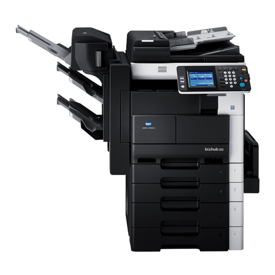
Konica Minolta bizhub 362 Service Manual
Field service
Hide thumbs
Also See for bizhub 362:
- User manual (450 pages) ,
- Installation manual (36 pages) ,
- Shortcut manual (28 pages)
Table of Contents
Advertisement
Quick Links
SERVICE MANUAL
The
The
This service manual is designed for copier
This service manual is designed for copier
with Firmware Ver. 4040-0100-G20-44-00X and onward.
with Firmware Ver. 4040-0100-G20-44-00X and onward.
is available only for North America.
is available only for North America.
FIELD SERVICE
2008.12
2008.12
Ver. 1.0
Ver. 1.0
Advertisement
Chapters
Table of Contents
Troubleshooting

Related Manuals for Konica Minolta bizhub 362


Summary of Contents for Konica Minolta bizhub 362
- Page 1 SERVICE MANUAL FIELD SERVICE is available only for North America. is available only for North America. This service manual is designed for copier This service manual is designed for copier with Firmware Ver. 4040-0100-G20-44-00X and onward. with Firmware Ver. 4040-0100-G20-44-00X and onward. 2008.12 2008.12 Ver.
-
Page 2: Table Of Contents
WARNING INDICATIONS ON THE MACHINE ............S-17 MEASURES TO TAKE IN CASE OF AN ACCIDENT ............S-20 Composition of the service manual ................. C-1 Notation of the service manual ..................C-2 bizhub 362/282/222 Main body OUTLINE ........................1 MAINTENANCE......................7 ADJUSTMENT/SETTING ................... 113 TROUBLESHOOTING .................... - Page 3 PC-108/PC-206 OUTLINE ........................1 MAINTENANCE ......................3 ADJUSTMENT/SETTING ..................... 13 TROUBLESHOOTING....................21 PC-407 OUTLINE ........................1 MAINTENANCE ......................3 ADJUSTMENT/SETTING ..................... 17 TROUBLESHOOTING....................25 JS-502 OUTLINE ........................1 MAINTENANCE ......................3 ADJUSTMENT/SETTING ....................5 FS-530/PU-501/OT-602 OUTLINE ........................1 MAINTENANCE ......................5 ADJUSTMENT/SETTING .....................
-
Page 4: Safety And Important Warning Items
IMPORTANT NOTICE Because of possible hazards to an inexperienced person servicing this product as well as the risk of damage to the product, KONICA MINOLTA BUSINESS TECHNOLOGIES, INC. (hereafter called the KMBT) strongly recommends that all servicing be performed only by KMBT-trained service technicians. -
Page 5: Safety Warnings
[1] MODIFICATIONS NOT AUTHORIZED BY KONICA MINOLTA BUSINESS TECHNOLOGIES, INC. KONICA MINOLTA brand products are renowned for their high reliability. This reliability is achieved through high-quality design and a solid service network. Product design is a highly complicated and delicate process where numerous mechanical, physical, and electrical aspects have to be taken into consideration, with the aim of arriving at proper tolerances and safety factors. - Page 6 SAFETY AND IMPORTANT WARNING ITEMS [2] POWER PLUG SELECTION In some countries or areas, the power plug provided with the product may not fit wall outlet used in the area. In that case, it is obligation of customer engineer (hereafter called the CE) to attach appropriate power plug or power cord set in order to connect the product to the supply.
-
Page 7: Checkpoints When Performing On-Site Service
SAFETY AND IMPORTANT WARNING ITEMS [3] CHECKPOINTS WHEN PERFORMING ON-SITE SERVICE KONICA MINOLTA brand products are extensively tested before shipping, to ensure that all applicable safety standards are met, in order to protect the customer and customer engi- neer (hereafter called the CE) from the risk of injury. However, in daily use, any electrical equipment may be subject to parts wear and eventual failure. - Page 8 SAFETY AND IMPORTANT WARNING ITEMS Power Plug and Cord WARNING • When using the power cord set (inlet type) that came with this product, make sure the connector is securely inserted in the inlet of the product. When securing measure is provided, secure the cord with the fixture properly.
- Page 9 SAFETY AND IMPORTANT WARNING ITEMS Wiring WARNING • Never use multi-plug adapters to plug multiple power cords in the same outlet. If used, the risk of fire exists. • When an extension cord is required, use a specified one. Current that can flow in the extension cord is limited, so using a too long extension cord may result in fire.
- Page 10 SAFETY AND IMPORTANT WARNING ITEMS Ventilation CAUTION • The product generates ozone gas during operation, but it will not be harmful to the human body. If a bad smell of ozone is present in the following cases, ventilate the room. a.
- Page 11 SAFETY AND IMPORTANT WARNING ITEMS Work Performed with the Product Powered On WARNING • Take every care when making adjustments or performing an operation check with the product powered. If you make adjustments or perform an operation check with the external cover detached, you may touch live or high-voltage parts or you may be caught in moving gears or the timing belt, leading to a risk of injury.
- Page 12 SAFETY AND IMPORTANT WARNING ITEMS Safety Checkpoints WARNING • Check electrode units such as a charging corona unit for deterioration and sign of leakage. Current can leak, leading to a risk of trouble or fire. • Before disassembling or adjusting the write unit (P/H unit) incorporating a laser, make sure that the power cord has been disconnected.
-
Page 13: Handling Of Consumables
SAFETY AND IMPORTANT WARNING ITEMS Safety Checkpoints WARNING • Make sure that all screws, components, wiring, connec- tors, etc. that were removed for safety check and mainte- nance have been reinstalled in the original location. (Pay special attention to forgotten connectors, pinched cables, forgotten screws, etc.) A risk of product trouble, electric shock, and fire exists. - Page 14 SAFETY AND IMPORTANT WARNING ITEMS Handling of Service Materials CAUTION • Use only a small amount of cleaner at a time and take care not to spill any liquid. If this happens, immediately wipe it off. A risk of fire exists. •...
- Page 15 SAFETY AND IMPORTANT WARNING ITEMS [4] Used Batteries Precautions ALL Areas CAUTION Danger of explosion if battery is incorrectly replaced. Replace only with the same or equivalent type recommended by the manufacturer. Dispose of used batteries according to the manufacturer’s instructions. Germany VORSICHT! Explosionsgefahr bei unsachgemäßem Austausch der Batterie.
-
Page 16: Internal Laser Radiation
SAFETY AND IMPORTANT WARNING ITEMS [5] Laser Safety • This is a digital machine certified as a class 1 laser product. There is no possibility of danger from a laser, provided the machine is serviced according to the instruction in this manual. - Page 17 SAFETY AND IMPORTANT WARNING ITEMS the U.S.A., Canada (CDRH Regulation) • This machine is certified as a Class I Laser product under Radiation Performance Stan- dard according to the Food, Drug and Cosmetic Act of 1990. Compliance is mandatory for Laser products marketed in the United States and is reported to the Center for Devices and Radiological Health (CDRH) of the U.S.
- Page 18 SAFETY AND IMPORTANT WARNING ITEMS Finland, Sweden VARO! • Avattaessa ja suojalukitus ohitettaessa olet alttiina näkymättömälle lasersäteilylle. Älä katso säteeseen. LOUKAN 1 LASERLAITE KLASS 1 LASER APPARAT VAROITUS! • Laitteen Käyttäminen muulla kuin tässä käyttöohjeessa mainitulla tavalla saattaa altistaa käyttäjän turvallisuusluokan 1 ylittävälle näkymättömälle lasersäteilylle. Puolijohdelaser Laserdiodin suurin teho 5 mW...
-
Page 19: Laser Safety Label
SAFETY AND IMPORTANT WARNING ITEMS Laser Safety Label • A laser safety labels is attached to the outside of the machine as shown below. * Only for the U.S.A. A11UP0C501DA Laser Caution Label • A laser caution label is attached to the inside of the machine as shown below. A11UP0C502DA Precautions For Handling The Laser Equipment •... -
Page 20: Warning Indications On The Machine
SAFETY AND IMPORTANT WARNING ITEMS WARNING INDICATIONS ON THE MACHINE Caution labels shown are attached in some areas on/in the machine. When accessing these areas for maintenance, repair, or adjustment, special care should be taken to avoid burns and electric shock. CAUTION A11UP0C503DA S-17... - Page 21 SAFETY AND IMPORTANT WARNING ITEMS High voltage A11UP0C504DA S-18...
- Page 22 SAFETY AND IMPORTANT WARNING ITEMS High voltage A11UP0C505DA CAUTION: • You may be burned or injured if you touch any area that you are advised not to touch by any caution label. Do not remove caution labels. If any caution label has come off or soiled and therefore the caution cannot be read, contact our Service Office.
-
Page 23: Measures To Take In Case Of An Accident
MEASURES TO TAKE IN CASE OF AN ACCIDENT MEASURES TO TAKE IN CASE OF AN ACCIDENT 1. If an accident has occurred, the distributor who has been notified first must immediately take emergency measures to provide relief to affected persons and to prevent further damage. -
Page 24: Composition Of The Service Manual
Composition of the service manual This service manual consists of Theory of Operation section and Field Service section to explain the main machine and its corresponding options. Theory of Operation section gives, as information for the CE to get a full understanding of the product, a rough outline of the object and role of each function, the relationship between the electrical system and the mechanical system, and the timing of operation of each part. -
Page 25: Notation Of The Service Manual
Notation of the service manual A. Product name In this manual, each of the products is described as follows: (1) IC board: Standard printer (2) bizhub 362/282/222: Main body (3) Microsoft Windows 98: Windows 98 Microsoft Windows Me: Windows Me Microsoft Windows NT 4.0:... - Page 26 SERVICE MANUAL FIELD SERVICE Main body 2008.12 Ver. 1.0...
-
Page 27: Revision History
Revision history After publication of this service manual, the parts and mechanism may be subject to change for improvement of their performance. Therefore, the descriptions given in this service manual may not coincide with the actual machine. When any change has been made to the descriptions in the service manual, a revised version will be issued with a revision mark added as required. - Page 28 Field Service Ver. 1.0 Dec. 2008 CONTENTS bizhub 362/282/222 Main body OUTLINE System configuration....................1 Product specifications ..................... 3 MAINTENANCE Periodical check ...................... 7 Maintenance items....................7 3.1.1 bizhub 362 ....................7 3.1.2 bizhub 282 ....................9 3.1.3 bizhub 222 ....................12 Maintenance parts ....................
- Page 29 Field Service Ver. 1.0 Dec. 2008 Service tool ......................40 CE Tool list ......................40 Firmware upgrade....................41 Preparations for Firmware rewriting ..............41 5.1.1 Service environment ................... 41 5.1.2 Writing into the Compact flash..............41 5.1.3 Checking ROM version ................41 Firmware rewriting by the compact flash ............
- Page 30 Field Service Ver. 1.0 Dec. 2008 6.3.17 Power Supply Unit..................61 6.3.18 High Voltage Unit ..................62 6.3.19 MFBS Board ....................63 6.3.20 Inverter Board ..................... 64 6.3.21 BCRS Board ....................65 6.3.22 CCD Unit..................... 66 6.3.23 Operation Board..................70 6.3.24 Manual Bypass Unit ..................
- Page 31 Field Service Ver. 1.0 Dec. 2008 6.4.10 Paper Dust Remover ................101 6.4.11 Transport Roller ..................101 6.4.12 Scanner Rails ................... 102 6.4.13 Bushings ....................102 6.4.14 Mirrors....................... 102 6.4.15 Lens ......................103 6.4.16 Original Scanning Glass ................103 6.4.17 Original Glass ...................
- Page 32 Field Service Ver. 1.0 Dec. 2008 8.4.2 Alarm Volume.................... 127 8.4.3 Line Monitor Sound................... 127 8.4.4 Job Complete Beep .................. 127 8.4.5 Panel Cleaning..................127 8.4.6 Dehumidify ....................127 8.4.7 Toner Supply ..................... 128 8.4.8 Memory RX ON/OFF ................128 8.4.9 POP3 RX ....................
- Page 33 Field Service Ver. 1.0 Dec. 2008 10.4.6 Original Size Detecting Option..............167 10.5 Settings in the Administrator # Initialize............167 10.6 Settings in the Counter..................167 10.6.1 Checking the counter reading..............167 10.6.2 Clearing readings of all counters at once ..........167 10.6.3 Clearing the reading of a specific counter ..........
- Page 34 Field Service Ver. 1.0 Dec. 2008 10.10.5 Calling the Maintenance ................199 10.10.6 Calling the Center from the Administrator ..........199 10.10.7 Checking the transmission log ..............199 10.10.8 Detail on settings ..................200 10.10.9 List of the CS Remote Care error code............. 205 10.10.10 Troubleshooting for CS Remote Care ............
- Page 35 Field Service Ver. 1.0 Dec. 2008 14.3.2 Touch Panel Adjustment ................226 14.3.3 Marketing Area ..................226 14.3.4 Image Data Clear..................226 14.3.5 Clear FAX Setting ..................227 14.3.6 Date/Time Setting ..................227 14.3.7 Trouble Reset.................... 227 Mechanical adjustment ..................228 15.1 Mechanical adjustment of the scanner section ..........
- Page 36 Field Service Ver. 1.0 Dec. 2008 17.3.9 Misfeed at Tray 3 take-up/Vertical Transport section (PC-206) ....248 17.3.10 Misfeed at Tray 4 take-up/Vertical Transport section (PC-206) ....249 17.3.11 Misfeed at LCT take-up/Vertical Transport section (PC-407) ....250 Malfunction code ....................251 18.1 Trouble code .....................
- Page 37 Field Service Ver. 1.0 Dec. 2008 18.3.31 CD004: HDD error ..................266 Power supply trouble................... 267 19.1 Machine is not Energized at All (PU1 Operation Check)........267 19.2 Only the Power Supply Cooling Fan Motor turns..........267 19.3 The Start key (LED) on the control panel blinks orange........268 Image quality problem..................
- Page 38 Field Service Ver. 1.0 Dec. 2008 22.5 PC-108/PC-206 (Option) .................. 298 22.6 PC-407 (Option)....................299 22.7 JS-502 (Option) ....................300 22.8 FS-530 (Option) ....................301 22.9 PU-501 (Option)....................302 22.10 MT-502 (Option)....................303 22.11 SD-507 (Option)....................304 Connector layout drawing..................305 Timing chart ......................
- Page 39 Field Service Ver. 1.0 Dec. 2008 Blank Page...
-
Page 40: Outline
Field Service Ver. 1.0 Dec. 2008 1. System configuration OUTLINE System configuration 1/2 System Front View [17] [16] [15] [14] [13] [12] [10] [11] A11UF1E500DA Original Cover (OC-510) [10] Paper Feed Cabinet (PC-108) Stamp Unit (SP-501) [11] Desk (DK-506) Reverse Automatic Document Feeder [12] Finisher (FS-530) (DF-620) - Page 41 1. System configuration Field Service Ver. 1.0 Dec. 2008 2/2 System Rear View [10] DK-506 PC-206 PC-108 PC-407 A11UF1E501DA Machine Scanner Unit (SU-501) *1 Fax Kit (FK-503) Expanded Memory Unit (EM-303/EM-304/EM-305) *1 Fax Multi Line (ML-502) Hard Disk (HD-504) *2 Local Interface kit (EK-502) Security Kit (SC-504) Dehumidifier Heater 1C...
-
Page 42: Product Specifications
Leading edge: 4 mm (1/4 inch), Trailing edge: 4 mm (1/4 inch), Image Loss Rear edge: 4 mm (1/4 inch), Front edge: 4 mm (1/4 inch) 4.8 sec. or less (bizhub 362) First Copy Time 5.3 sec. or less (bizhub 282) (Tray1, A4, full size) 5.3 sec. - Page 43 2. Product specifications Field Service Ver. 1.0 Dec. 2008 C. Types of Paper Paper Source Paper Source Tray1 Tray2 Multiple Bypass Plain paper ❍ ❍ ❍ (56 to 90 g/m / 15 to 24 lb) Translucent paper ❍ OHP transparencies Thick paper (91 to 210 g/m Copy ❍...
- Page 44 Field Service Ver. 1.0 Dec. 2008 2. Product specifications F. Built-in Controllers Type Built-in type controller RM5231 PCL5e Emulation Printer Driver PCL6 (XL Ver. 2.1)Emulation PostScript3 Emulation (3011.xx.xx) Scan Driver TWAIN driver Windows NT 4.0, Windows 2000 (Service Pack 4 or later), Server Windows Server 2003, or Windows Server 2008 OS Compatibility...
- Page 45 2. Product specifications Field Service Ver. 1.0 Dec. 2008 Blank Page...
-
Page 46: Maintenance
Field Service Ver. 1.0 Dec. 2008 3. Periodical check MAINTENANCE Periodical check Maintenance items 3.1.1 bizhub 362 A. Periodical parts replacement 1 (per 50,000-print) Number of Lubri- Descrip- Class Parts to be replaced Check Clean Replace personnel cation tions Paper take-up and ●... - Page 47 3. Periodical check Field Service Ver. 1.0 Dec. 2008 C. Periodical parts replacement 3 (per 150,000-print) Number of Lubri- Descrip- Class Parts to be replaced Check Clean Replace personnel cation tions Paper take-up and image ● conditions Overall ● ● Appearance Transport ●...
-
Page 48: Bizhub 282
Field Service Ver. 1.0 Dec. 2008 3. Periodical check F. Periodical parts replacement 6 (per 400,000-print) Number of Lubri- Descrip- Class Parts to be replaced Check Clean Replace personnel cation tions Paper take-up and ● image conditions Overall ● ● Appearance ●... - Page 49 3. Periodical check Field Service Ver. 1.0 Dec. 2008 B. Periodical parts replacement 2 (per 80,000-print) Number of Lubri- Descrip- Class Parts to be replaced Check Clean Replace personnel cation tions Paper take-up and ● image conditions Overall ● ● Appearance ●...
- Page 50 Field Service Ver. 1.0 Dec. 2008 3. Periodical check E. Periodical parts replacement 5 (per 300,000-print) Number of Lubri- Descrip- Class Parts to be replaced Check Clean Replace personnel cation tions Paper take-up and ● image conditions Overall ● ● Appearance ●...
-
Page 51: Bizhub 222
3. Periodical check Field Service Ver. 1.0 Dec. 2008 3.1.3 bizhub 222 A. Periodical parts replacement 1 (per 50,000-print) Number of Lubri- Descrip- Class Parts to be replaced Check Clean Replace personnel cation tions Paper take-up and ● image conditions Overall ●... - Page 52 Field Service Ver. 1.0 Dec. 2008 3. Periodical check E. Periodical parts replacement 5 (per 260,000-print) Number of Lubri- Descrip- Class Parts to be replaced Check Clean Replace personnel cation tions Paper take-up and ● image conditions Overall ● ● Appearance ●...
-
Page 53: Maintenance Parts
4040-R711-## P.37 section areas only. 110 V areas 4040-R712-## only. Transfer Transfer Roller Unit 150 K 4040-R725-## P.38 section bizhub 362 100 K Photo Conductor bizhub 282 80 K P.34 Unit bizhub 222 65 K bizhub 362 100 K Developer... - Page 54 3. Periodical check Actual Ref.Page No Classification Parts name durable Parts No. Descriptions in this ntity cycle *1 manual bizhub 362 400 K 4040-2093-## Processing Toner Filter bizhub 282 320 K 4040-2093-## P.33 section (Main body) bizhub 222 260 K...
-
Page 55: Cleaning Parts
3. Periodical check Field Service Ver. 1.0 Dec. 2008 3.2.2 Cleaning parts Ref.Page No Classification Parts name Actual durable cycle *1 Descriptions in this manual Pick-up Roller 50 K Feed Roller 50 K Separation Roller 50 K DF-620 Misc. rollers and rolls 50 K Scanning Guide 50 K... -
Page 56: Concept Of Parts Life
Count the number of times paper is fed out. Not stopped 450 K *1: On the bizhub 362 *2: The setting can be changed to “stopped” by using the soft switch of the Tech. Rep. mode. *3: The Photo Conductor Unit and Developer have to be replaced together. -
Page 57: Maintenance Procedure (Periodical Check Parts)
3. Periodical check Field Service Ver. 1.0 Dec. 2008 Maintenance procedure (Periodical check parts) 3.4.1 Replacing the Bypass Tray Feed Roller 1. Remove the Multi Bypass Unit. See P.72 2. Remove five screws [1] and the Man- ual Bypass Unit Lower Frame [2]. 4037F2C518DA 3. -
Page 58: Replacing The Bypass Tray Separation Roller Assy
Field Service Ver. 1.0 Dec. 2008 3. Periodical check 3.4.2 Replacing the Bypass Tray Separation Roller Assy 1. Remove the Multi Bypass Unit. See P.72 2. Remove two screws [1], and remove Bypass Paper Separation Roller fix- ing bracket Assy [2]. 4037F2C515DA 3. -
Page 59: Replacing The Tray 1 Feed Roller
3. Periodical check Field Service Ver. 1.0 Dec. 2008 3.4.3 Replacing the Tray 1 Feed Roller 1. Remove the screw [1] and, holding the stopper [2], remove Tray 1 [3]. A11UF2C500DA 2. Remove two screws [4] and the Con- nector Cover [5]. A11UF2C501DA 3. -
Page 60: Replacing The Tray 1 Pick-Up Roller
Field Service Ver. 1.0 Dec. 2008 3. Periodical check 6. Remove the C-clip [12] and the bear- [12] ing [13]. [13] 4040F2C513DA 7. Remove the C-clip [14], E-ring [15], [14] [15] bearing [16] and spring [17] to remove the Tray 1 Feed Roller Assy [18]. - Page 61 3. Periodical check Field Service Ver. 1.0 Dec. 2008 3. Remove the Connector [6]. 4. Remove two screws [7] and the Tray 1 Feed Roller Assy [8]. A11UF2C502DA 5. Remove four screws [9] and the Tray [10] [11] 1 Feed Roller Assy Cover [10] and the Tray 1 Separator Roll Assy [11].
-
Page 62: Replacing The Tray 1 Separation Roller Assy
Field Service Ver. 1.0 Dec. 2008 3. Periodical check 3.4.5 Replacing the Tray 1 Separation Roller Assy 1. Remove the screw [1] and, holding the stopper [2], remove Tray 1 [3]. A11UF2C500DA 2. Remove two screws [4] and the Con- nector Cover [5]. - Page 63 3. Periodical check Field Service Ver. 1.0 Dec. 2008 6. Remove two Screws [12] and the Tray 1 Separation Roller installation plate Assy [13]. [12] [13] 4040F2C520DA 7. Remove two C-clips [14] and the [15] Tray 1 Separation Roller installation [14] plate [15].
-
Page 64: Replacing The Tray 2 Feed Roller
Field Service Ver. 1.0 Dec. 2008 3. Periodical check 3.4.6 Replacing the Tray 2 Feed Roller 1. Slide out the Tray 2. 2. Remove the Multi Bypass Unit. See P.72 3. Remove the Lower Right Cover [1]. 4040F2C524DA 4. Remove two screws [2] and the Transport Roller Cover [3]. -
Page 65: Replacing The Tray 2 Pick-Up Roller
3. Periodical check Field Service Ver. 1.0 Dec. 2008 9. Remove two C-clips [14] and the bearing [15]. [14] [14] [15] 4040F2C529DA 10. Remove the C-clip [16], E-ring [17], [16] [17] bearing [18] and spring [19] to remove the Tray 2 Feed Roller Assy [20]. - Page 66 Field Service Ver. 1.0 Dec. 2008 3. Periodical check 5. Remove two screws [4] and the Mis- feed Clearing Cover [5]. 4040F2C527DA 6. Unplug two connectors [6]. 7. Remove three screws [7] and the Tray 2 Feed Roller Assy [8]. 4040F2C591DA 8.
-
Page 67: Replacing The Tray 2 Separation Roller
3. Periodical check Field Service Ver. 1.0 Dec. 2008 3.4.8 Replacing the Tray 2 Separation Roller 1. Slide out the Tray 2. 2. Remove the Multi Bypass Unit. See P.72 3. Remove the Lower Right Cover [1]. 4040F2C524DA 4. Remove two screws [2] and the Transport Roller Cover [3]. - Page 68 Field Service Ver. 1.0 Dec. 2008 3. Periodical check 9. Remove two Screws [14] and the [15] Tray 2 Separation Roller installation plate Assy [15]. [14] 4040F2C536DA 10. Remove two C-clips [16] and the [17] Tray 2 Separation Roller installation plate [17].
-
Page 69: Replacing Of The Registration Roller Bearings And Registration Roller Gears 1, 2
3. Periodical check Field Service Ver. 1.0 Dec. 2008 3.4.9 Replacing of the Registration Roller Bearings and Registration Roller Gears 1, 2 1. Open the Right Door [1]. 4040F2C540DA 2. Remove two E-rings [2], Registration Roller Gears 1 [3] and Registration Roller Gears 2 [4]. -
Page 70: Cleaning Of The Paper Dust Remover
Field Service Ver. 1.0 Dec. 2008 3. Periodical check 5. Remove the E-ring [11] and unplug the connector [12]. Then, remove the Registration Roller Clutch [13]. 6. Remove the washer [14] and two wave washers [15]. [12] [13] [14] [11] [15] 4040F2C548DA 7. -
Page 71: Replacing Of The Toner Filter (Developing Unit)
3. Periodical check Field Service Ver. 1.0 Dec. 2008 3.4.11 Replacing of the Toner Filter (Developing Unit) 1. Open the Right Door. 2. Remove the IU [1]. 4040F2C555DA 3. Remove the Toner Filter Cover [2]. 4040F2C655DA 4. Remove the Toner Filter (Develop- ing Unit) [3]. -
Page 72: Replacing Of The Toner Filter (Main Body)
Field Service Ver. 1.0 Dec. 2008 3. Periodical check 3.4.12 Replacing of the Toner Filter (Main body) 1. Remove the screw [1] and the Toner Filter Rear Cover [2]. 4040F2C558DA 2. Pull on the tape portion [3] and peel off the Toner Filter (Main body) [4]. NOTE •... -
Page 73: Replacement Of The Photo Conductor Unit And Developer
3. Periodical check Field Service Ver. 1.0 Dec. 2008 3.4.14 Replacement of the Photo Conductor Unit and Developer 1. Select Tech. Rep. Mode → [Counter] → [Special Parts Counter] → [PC Life]. 2. Press the Clear key to clear the counter value. 3. - Page 74 Field Service Ver. 1.0 Dec. 2008 3. Periodical check 9. Remove the liner from the mylar sheet [8] furnished with the drum. 4040F2C773DA 10. Attach two mylar sheets [9]. NOTE • Make sure that the collar is com- pletely covered with the mylar sheet [9].
- Page 75 3. Periodical check Field Service Ver. 1.0 Dec. 2008 12. Set the developer [11] while rotating the gear in the direction of the arrow. [11] NOTE • Not touching the gear of A side. • Be sure not to let starter get inside the collar.
-
Page 76: Replacing The Unit
Field Service Ver. 1.0 Dec. 2008 3. Periodical check Replacing the unit 3.5.1 Replacement of the Fusing Unit CAUTION • From the safety viewpoint, the Fusing Unit is replaced as a unit. No parts intended for other models should be used for the Fusing Unit of this machine. Note, how- ever, that the thermistor and several other parts mentioned in this machine may be replaced as an individual part with a new one. -
Page 77: Replacement Of The Transfer Roller Unit
3. Periodical check Field Service Ver. 1.0 Dec. 2008 10. Remove the screw [9] and the Con- nector Cover [10]. [10] 4040F2C658DA 11. Remove two screws [11] and unplug three connectors [12]. Then, remove the Fusing Unit [13]. [12] [13] [12] [12] [11]... -
Page 78: Replacement Of The Developing Unit
Field Service Ver. 1.0 Dec. 2008 3. Periodical check 3.5.3 Replacement of the Developing Unit 1. Select Tech. Rep. Mode → [Counter] → [Special Parts Counter] → [Developer]. 2. Press the Clear key to clear the counter value. 3. Turn OFF the main power switch. NOTE •... -
Page 79: Service Tool
4. Service tool Field Service Ver. 1.0 Dec. 2008 Service tool CE Tool list Tool name Shape Personnel Parts No. Remarks Thermistor Holding/Check 4040-7901-01 4040F2C728DA... -
Page 80: Firmware Upgrade
Field Service Ver. 1.0 Dec. 2008 5. Firmware upgrade Firmware upgrade Preparations for Firmware rewriting 5.1.1 Service environment • Drive which enables writing/reading of Compact flash • Compact flash (with 32 MB or more) NOTE • Make sure that the file system on the compact flash is “FAT”. 5.1.2 Writing into the Compact flash •... - Page 81 5. Firmware upgrade Field Service Ver. 1.0 Dec. 2008 NOTE • Be sure to turn ON the sub power switch first before turning ON the main power switch. 4. Turn ON the main power switch. 5. The firmware upgrading sequence will start.
-
Page 82: Engine
Field Service Ver. 1.0 Dec. 2008 5. Firmware upgrade 5.2.2 Engine NOTE • Make sure that the MSC firmware has not been copied to the compact flash card. • To upgrade both the engine firmware and Finisher firmware at the same time, they must first be copied onto a single compact flash. - Page 83 5. Firmware upgrade Field Service Ver. 1.0 Dec. 2008 9. Select [Engine] and touch [Enter]. NOTE • Touch [Finisher] also if the Finisher firmware is to be upgraded at the same time. 4040F2E768DA 10. Select [Yes] and touch [Enter]. 4040F2E769DA 11.
-
Page 84: Firmware Rewriting By The Internet Isw
Field Service Ver. 1.0 Dec. 2008 5. Firmware upgrade Firmware rewriting by the Internet ISW 5.3.1 Outline • [Internet ISW] is the system which gives the instruction for updating the firmware with the CS Remote Care, so the main body will automatically receive the firmware from the pro- gram server over a network for updating. -
Page 85: Firmware Rewriting Procedure
5. Firmware upgrade Field Service Ver. 1.0 Dec. 2008 5.3.4 Firmware rewriting procedure • For the firmware update procedure using CS Remote Care, refer to CS Remote Care Center Manual. • For detailed error information relating to CS Remote Care, refer to “ADJUSTMENT/SET- TING: CS Remote Care.”... -
Page 86: Other
Field Service Ver. 1.0 Dec. 2008 6. Other Other Disassembly/Adjustment prohibited items A. Screws to which blue paint or green paint is applied • Blue paint or green paint is applied to some screws to prevent them from coming loose. •... -
Page 87: Disassembly/Assembly/Cleaning List (Other Parts)
6. Other Field Service Ver. 1.0 Dec. 2008 Disassembly/Assembly/Cleaning list (Other parts) 6.2.1 Disassembly/Assembly parts list Section Part name Ref.Page Original Scanning Glass P.50 Original Glass P.50 Front Holding Bracket P.50 Control Panel P.57 Upper Front Cover P.54 Middle Front Cover P.54 Front Cover P.54... -
Page 88: Cleaning Parts List
Field Service Ver. 1.0 Dec. 2008 6. Other Section Part name Ref.Page Manual Bypass Unit P.72 PH Unit P.72 Toner Hopper Unit P.75 Unit Toner Replenishing Drive Unit P.75 Duplex Unit P.77 Switch Back Unit P.77 Scanner Motor P.78 Exposure Lamp P.80 Exposure Unit P.79... -
Page 89: Disassembly/Assembly Procedure
6. Other Field Service Ver. 1.0 Dec. 2008 Disassembly/Assembly procedure 6.3.1 IR Upper Left Cover/Original Scanning Glass/Front Holding Bracket/Origi- nal Glass A11UF2C504DA 1. Remove two Screws [1], and remove the IR Upper Left Cover [2]. 2. Remove the Original Scanning Glass [3]. 3. -
Page 90: Upper Rear Cover
Field Service Ver. 1.0 Dec. 2008 6. Other 3. Remove the four screws [5], one wave washer [6], and the Tray Rear Cover [7]. CAUTION • Make sure that the wave washer is installed at the correct position. 4040F2C660DA 6.3.3 Upper Rear Cover 1. -
Page 91: Ir Right Cover/Rear Cover
6. Other Field Service Ver. 1.0 Dec. 2008 6.3.5 IR Right Cover/Rear Cover A11UF2C508DA 1. Open the Right Door. 2. Remove the Upper Rear Cover. See P.51 3. Remove the IR Right Cover [1]. 4. Remove thirteen Screws [2], and remove the Rear Cover [3]. 6.3.6 Front Door 1. -
Page 92: Paper Output Cover/Lower Front Cover
Field Service Ver. 1.0 Dec. 2008 6. Other 6.3.7 Paper Output Cover/Lower Front Cover A11UF2C510DA 1. Open the Front Door [1]. 2. Remove three screws [2] and the Paper Output Cover [3]. 3. Slide out the Tray 1. 4. Remove two screws [4] and the Con- nector Cover [5]. -
Page 93: Upper Front Cover/Middle Front Cover/Front Cover
6. Other Field Service Ver. 1.0 Dec. 2008 6.3.8 Upper Front Cover/Middle Front Cover/Front Cover 1. Open the Right Door. 2. Remove the Front Right Cover. See P.51 3. Remove the screw [1] and the Upper Front Cover [2]. A11UF2C513DA 4. -
Page 94: Ir Left Cover/Rear Left Cover/Left Cover
Field Service Ver. 1.0 Dec. 2008 6. Other 9. Remove four screws [3] and the Front Cover [4]. A11UF2C514DA 6.3.9 IR Left Cover/Rear Left Cover/Left Cover A11UF2C516DA 1. Remove the Upper Rear Cover. See P.51 2. Remove the IR Left Cover [1]. 3. -
Page 95: Rear Manual Bypass Cover/Front Manual Bypass Cover/Lower Right Cover
6. Other Field Service Ver. 1.0 Dec. 2008 6.3.10 Rear Manual Bypass Cover/Front Manual Bypass Cover/Lower Right Cover A11UF2C517DA 1. Remove two screws [1] and the Rear Manual Bypass Cover [2]. 2. Remove the screw [3] and the Front Manual Bypass Cover [4]. 3. -
Page 96: Control Panel
Field Service Ver. 1.0 Dec. 2008 6. Other 6.3.11 Control Panel 1. Remove two screw covers [1]. 4040F2C592DA 2. Remove the four screws [2] on the sides of the Control Panel. 4040F2C593DA 3. Disconnect the connector [3] and remove the Control Panel [4]. 4040F2C594DA 6.3.12 Tray 1... -
Page 97: Tray 2
6. Other Field Service Ver. 1.0 Dec. 2008 6.3.13 Tray 2 1. Slide out the Tray 2 [1]. 2. Remove the screw [2] and, holding the stopper [3], remove the Tray 2 [1]. A11UF2C503DA 6.3.14 Mechanical Control Board Cover 1. Remove the Upper Rear Cover. See P.51 2. -
Page 98: Fd Paper Size Board 1
Field Service Ver. 1.0 Dec. 2008 6. Other 6.3.15 FD Paper Size Board 1 1. Remove the Upper Rear Cover. See P.51 2. Remove the Rear Cover. See P.52 3. Remove five screws [1] and the Mechanical Control Board Cover [2]. 4040F2C561DA 4. -
Page 99: Fd Paper Size Board 2
6. Other Field Service Ver. 1.0 Dec. 2008 6.3.16 FD Paper Size Board 2 1. Remove the Upper Rear Cover. See P.51 2. Remove the Rear Cover. See P.52 3. Remove five screws [1] and the Mechanical Control Board Cover [2]. 4040F2C561DA 4. -
Page 100: Power Supply Unit
Field Service Ver. 1.0 Dec. 2008 6. Other 6.3.17 Power Supply Unit 1. Remove the Paper Output Cover. See P.53 2. Remove the Upper Rear Cover. See P.51 3. Remove the Rear Cover. See P.52 4. Remove the Rear Left Cover. See P.55 5. -
Page 101: High Voltage Unit
6. Other Field Service Ver. 1.0 Dec. 2008 6.3.18 High Voltage Unit 1. Open the Right Door. 2. Remove the Imaging Unit. 3. Remove the Upper Rear Cover. See P.51 4. Remove the Rear Cover. See P.52 5. Remove the Toner Suction Fan Motor. See P.87 6. -
Page 102: Mfbs Board
Field Service Ver. 1.0 Dec. 2008 6. Other 6.3.19 MFBS Board 1. Remove the Upper Rear Cover. See P.51 2. Remove the IR Right Cover. See P.52 3. Unplug the connector (CN7) [1]. NOTE • If the Fax Kit is mounted, discon- nect the two connectors (CN7 [1], CN6 [2]). -
Page 103: Inverter Board
6. Other Field Service Ver. 1.0 Dec. 2008 6.3.20 Inverter Board 1. Remove the IR Upper Left Cover. See P.50 2. Remove the Front Holding Bracket. See P.50 3. Remove the Original Glass. See P.50 4. Disconnect the connector [1] and remove the flat cable [2], screw [3], and the Inverter Board [4]. -
Page 104: Bcrs Board
Field Service Ver. 1.0 Dec. 2008 6. Other 6.3.21 BCRS Board 1. Remove the Upper Rear Cover. See P.51 2. Remove the IR Upper Left Cover. See P.50 3. Remove the Front Holding Bracket. See P.50 4. Remove the Original Glass. See P.50 5. -
Page 105: Ccd Unit
6. Other Field Service Ver. 1.0 Dec. 2008 6.3.22 CCD Unit A. Replacing Procedure 1. Remove the IR Upper Left Cover. See P.50 2. Remove the Front Holding Bracket. See P.50 3. Remove the Original Glass. See P.50 4. Remove six screws [1] and the CCD Unit Cover [2]. - Page 106 Field Service Ver. 1.0 Dec. 2008 6. Other 1. Screw the three adjusting screws [1] into the CCD Unit [2] only to half the thread length of each screw. 4030D591AB 4030D591AB 2. From the bottom side of the CCD Unit, adjust the dimension of the screw thread protrusion to 1.5 mm (at three places).
- Page 107 6. Other Field Service Ver. 1.0 Dec. 2008 Tilt and FD Deviation Adjustment Procedure Using Screws A and B • If tilt or deviation in the FD direction is as shown on the left A: Using an Allen wrench (3 mm), turn screw A counterclockwise. B: Using an Allen wrench (3 mm), turn screw B clockwise.
- Page 108 Field Service Ver. 1.0 Dec. 2008 6. Other CD Deviation Adjustment Procedure Using Adjustment Plate E • If deviation in the CD direction is as shown on the left 1. Using a flat-blade screwdriver, turn adjustment plate E counterclock- wise. Adjustment plate 4030D597AA...
-
Page 109: Operation Board
6. Other Field Service Ver. 1.0 Dec. 2008 6.3.23 Operation Board 1. Remove the Operation Panel. See P.57 2. Disconnect two connectors [1] and remove three flat cables [2] 3. Remove two screws [3] and the Operation Board 1 [4]. 4040F2C758DA 4. - Page 110 Field Service Ver. 1.0 Dec. 2008 6. Other 7. Remove the screw [12], two connec- [13] tors [13], and the Operation Board 2 [14] [14]. [12] [13] 4040F2C762DA 8. Remove two screws [15] and the Bracket [16]. [16] [15] 4040F2C763DA 9.
-
Page 111: Manual Bypass Unit
6. Other Field Service Ver. 1.0 Dec. 2008 6.3.24 Manual Bypass Unit 1. Remove the Rear Right Cover. See P.51 2. Remove the Lower Right Rear Cover. See P.50 3. Remove the Front Manual Bypass Cover. See P.56 4. Remove the Rear Manual Bypass Cover. See P.56 5. - Page 112 Field Service Ver. 1.0 Dec. 2008 6. Other 7. Remove four screws [5] and two har- ness protective metal brackets [6]. 4040F2C613DA 8. Remove the harness from the cord holder. 4040F2C614DA 9. Remove five screws [7] and the Mechanical Control Board Cover [8]. 4040F2C615DA 10.
- Page 113 6. Other Field Service Ver. 1.0 Dec. 2008 • When replacing the PH, install spacers according to the color of the labels affixed to the PH. Screw Position PH label color Green label No spacer No spacer No spacer Blue label No spacer 0.1 mm spacer 0.2 mm spacer...
-
Page 114: Toner Hopper Unit
Field Service Ver. 1.0 Dec. 2008 6. Other 6.3.26 Toner Hopper Unit 1. Open the Front Door. 2. Remove the screw [1] and the Toner Hopper Unit [2]. 4040F2C568DA 6.3.27 Toner Replenishing Drive Unit 1. Remove the Imaging Unit. 2. Remove the Front Door. See P.52 3. - Page 115 6. Other Field Service Ver. 1.0 Dec. 2008 10. Remove four screws [6] and the imaging unit protective metal bracket [7]. 4040F2C606DA 11. Unplug two connectors [8] and remove four screws [9] and the Toner Hopper Assy [10]. [10] 4040F2C607DA 12.
-
Page 116: Duplex Unit
Field Service Ver. 1.0 Dec. 2008 6. Other 6.3.28 Duplex Unit 1. Remove the Lower Right Rear Cover. See P.50 2. Disconnect the connector [1] and remove the screw [2] and ground wire [3]. 4040F2C569DA 3. Remove four screws [4] and the Duplex Unit [5]. -
Page 117: Scanner Motor
6. Other Field Service Ver. 1.0 Dec. 2008 5. Loosen the screw [4] in front. 6. Remove the screw [5] in front. 7. Loosen the screw [6] in the back. 8. Remove the screw [7] in the back. 4040F2C564DA 9. Remove the Switch Back Unit [8]. 4040F2C565DA 10. -
Page 118: Exposure Unit
Field Service Ver. 1.0 Dec. 2008 6. Other 4. Remove the spring [3], two screws [4] and the scanner motor [5]. 4040F2C690DA 6.3.31 Exposure Unit 1. Remove the IR Upper Left Cover. See P.50 2. Remove the Front Holding Bracket. See P.50 3. -
Page 119: Exposure Lamp
6. Other Field Service Ver. 1.0 Dec. 2008 6.3.32 Exposure Lamp 1. Remove the IR Upper Left Cover. See P.50 2. Remove the Front Holding Bracket. See P.50 3. Remove the Original Glass. See P.50 4. Move the Exposure Unit [1] to the removal position. -
Page 120: Scanner Drive Cables
Field Service Ver. 1.0 Dec. 2008 6. Other 6.3.33 Scanner Drive Cables A. Removal Procedure 1. Remove the Upper Rear Cover. See P.51 2. Remove the IR Upper Left Cover. See P.50 3. Remove the Front Holding Bracket. See P.50 4. - Page 121 6. Other Field Service Ver. 1.0 Dec. 2008 B. Reinstallation Procedure <General View> Rear Pulley E Pulley D Pulley G Scanner Drive Cable 4 Pulley H Pulley F Pulley C Scanner Drive Cable 2 Scanner Drive Cable 3 Pulley A Pulley B Front Scanner Drive Cable 1...
- Page 122 Field Service Ver. 1.0 Dec. 2008 6. Other <Rear> 4. Position the round bead [5] of the Scanner Drive Cable in the slit [6] in the pulley. NOTE • Make sure that the bead snugly rests in the slit in the pulley. 4040F2C718DA 5.
- Page 123 6. Other Field Service Ver. 1.0 Dec. 2008 10. Attach the Drive Gear [13] using one [13] screw. NOTE • Allow a clearance of about 0.1 mm between the Drive Gear and bush- ing. 4040F2C757DA 11. Mount the Scanner Motor Assy. See P.78 <Front>...
- Page 124 Field Service Ver. 1.0 Dec. 2008 6. Other 15. Wind Scanner Drive Cable 3 around [26] pulley H [25] and pulley F [26] and hook the bead to the side surface [25] [27] of the Scanner Frame. [27] 4040F2C726DA 16. Remove the pulley tape. 17.
-
Page 125: Main Motor
6. Other Field Service Ver. 1.0 Dec. 2008 6.3.34 Main Motor 1. Remove the Upper Rear Cover. See P.51 2. Remove the Rear Cover. See P.52 3. Remove the Rear Right Cover. See P.51 4. Remove two screws [1] and the Ozone Filter Assy [2]. -
Page 126: Fusing Unit Cooling Fan Motor
Field Service Ver. 1.0 Dec. 2008 6. Other 6.3.36 Fusing Unit Cooling Fan Motor 1. Remove the Upper Rear Cover. See P.51 2. Remove the Rear Cover. See P.52 3. Remove three wiring saddles [1] and disconnect the connector (PJ33) [2]. 4040F2C622DA 4. -
Page 127: Temperature/Humidity Sensor
6. Other Field Service Ver. 1.0 Dec. 2008 6.3.38 Temperature/humidity Sensor 1. Remove the Upper Rear Cover. See P.51 2. Remove the Rear Cover. See P.52 3. Disconnect the connector [1], widen the two tabs [2], and remove the Temperature/humidity Sensor [3]. 4040F2C620DA 6.3.39 ATDC Sensor... - Page 128 Field Service Ver. 1.0 Dec. 2008 6. Other 7. Remove the Toner Supply Port [7]. 4040F2C580DA 8. Remove the developer [8]. 4040F2C581DA Removal of the Developer • Dump the developer on the Sleeve Roller by rotating the gear in the direction of the arrow.
-
Page 129: Thermistor
6. Other Field Service Ver. 1.0 Dec. 2008 6.3.40 Thermistor 1. Remove the Fusing Unit. See P.37 2. Snap off the C-clip [1] and remove the Fusing Entrance Guide Plate [2]. 4040F2C625DA 3. Remove two shoulder screws [3], the screw [4], and the Exit Rolls 2 Assy [5]. - Page 130 Field Service Ver. 1.0 Dec. 2008 6. Other Bracket Fusing Roller Sub Thermistor side Fusing Roller Thermistor side 4040F2E753DA 6. Press the Thermistor Holding/Check Jig [9] up against the bracket and fix it in position. CAUTION • Press the Thermistor Holding/ Check Jig squarely so as to elimi- nate no gap between the bracket that supports the thermistor and...
-
Page 131: Paper Exit Roll 1
6. Other Field Service Ver. 1.0 Dec. 2008 6.3.41 Paper Exit Roll 1 1. Remove the Fusing Unit. See P.37 2. Remove four screws [1] and four Exit Rolls 1 Assy [2]. 4040F2C641DA 3. Remove the Exit Roll 1 [3]. 4040F2C642DA 6.3.42 Paper Exit Roll 2... -
Page 132: Separation Claw
Field Service Ver. 1.0 Dec. 2008 6. Other 4. Remove two wiring saddles [6] and the harness. 4040F2C730DA 5. Disconnect the connector [7] of the Exit Sensor and remove the Exit Rolls 2 Assy [8]. 4040F2C431DA 6. Remove the screw [9] and the Sepa- ration Claw Assy [10]. - Page 133 6. Other Field Service Ver. 1.0 Dec. 2008 3. Remove two shoulder screws [3], the screw [4], and the Exit Rolls 2 Assy [5]. 4040F2C643DA 4. Remove two wiring saddles [6] and the harness. 4040F2C730DA 5. Disconnect the connector [7] of the Exit Sensor and remove the Exit Rolls 2 Assy [8].
-
Page 134: Cleaning Procedure
Field Service Ver. 1.0 Dec. 2008 6. Other Cleaning procedure NOTE • The alcohol described in the cleaning procedure represents the isopropyl alcohol. 6.4.1 Manual Bypass Feed Roller 1. Remove the Manual Bypass Unit. See P.72 2. Remove two screws [1] and the Man- ual Bypass Separation Fixing Bracket Assy [2]. -
Page 135: Tray 1 Feed Roller
6. Other Field Service Ver. 1.0 Dec. 2008 6.4.3 Tray 1 Feed Roller 1. Remove the screw [1] and, holding the stopper [2], remove the Tray 1 [3]. A11UF2C500DA 2. Remove two screws [4] and the Con- nector Cover [5]. A11UF2C501DA 3. -
Page 136: Tray 1 Pick-Up Roller
Field Service Ver. 1.0 Dec. 2008 6. Other 6.4.4 Tray 1 Pick-up Roller 1. Remove the screw [1] and, holding the stopper [2], remove the Tray 1 [3]. A11UF2C500DA 2. Remove two screws [4] and the Con- nector Cover [5]. A11UF2C501DA 3. -
Page 137: Tray 1 Separation Roller
6. Other Field Service Ver. 1.0 Dec. 2008 6.4.5 Tray 1 Separation Roller 1. Remove the screw [1] and, holding the stopper [2], remove the Tray 1 [3]. A11UF2C500DA 2. Remove two screws [4] and the Con- nector Cover [5]. A11UF2C501DA 3. -
Page 138: Tray 2 Feed Roller
Field Service Ver. 1.0 Dec. 2008 6. Other 6.4.6 Tray 2 Feed Roller 1. Slide out the Tray 2. 2. Remove the Manual Bypass Unit. See P.72 3. Remove the Lower Right Cover [1]. 4040F2C524DA 4. Remove two connectors [2]. 5. -
Page 139: Tray 2 Separation Roller
6. Other Field Service Ver. 1.0 Dec. 2008 4. Remove two connectors [2]. 5. Remove three screws [3] and the Tray 2 Feed Roller Assy [4]. 4040F2C595DA 6. Using a soft cloth dampened with alcohol, wipe the Tray 2 Pick-up Roller [5] clean of dirt. -
Page 140: Registration Roller
Field Service Ver. 1.0 Dec. 2008 6. Other 6.4.9 Registration Roller 1. Remove the Paper Dust Remover See P.31 2. Using a soft cloth dampened with alcohol, wipe the Registration Roller [1] clean of dirt. 4040F2C543DA 6.4.10 Paper Dust Remover 1. -
Page 141: Scanner Rails
6. Other Field Service Ver. 1.0 Dec. 2008 6.4.12 Scanner Rails 1. Remove the IR Upper Left Cover. See P.50 2. Remove the Front Holding Bracket. See P.50 3. Remove the Original Glass. See P.50 4. Using a soft cloth dampened with alcohol, wipe four Scanner Rails [1] 4040F2C704DA clean of dirt. -
Page 142: Lens
Field Service Ver. 1.0 Dec. 2008 6. Other 6.4.15 Lens 1. Remove the IR Upper Left Cover. See P.50 2. Remove the Front Holding Bracket. See P.50 3. Remove the Original Glass. See P.50 4. Remove six screws [1] and the CCD Unit Cover [2]. -
Page 143: Charge Neutralizing Plate
6. Other Field Service Ver. 1.0 Dec. 2008 6.4.18 Charge Neutralizing Plate 1. Open the Right Door. 2. Wipe the Charge Neutralizing Plate [1] clean of dirt with a cloth. 4040F2C553DA 6.4.19 Ds Collar 1. Turn OFF the main power switch. NOTE •... - Page 144 Field Service Ver. 1.0 Dec. 2008 6. Other 6. Using a soft cloth dampened with alcohol, wipe the Ds Collar [7] clean of dirt. NOTE • Make sure the alcohol does not touch the Developer Roller. 4040F2C588DA 7. Turn ON the main power switch.
-
Page 145: Mount Kit Mk-709
6. Other Field Service Ver. 1.0 Dec. 2008 Mount Kit MK-709 1. Remove the Upper Rear Cover. See P.51 2. Remove the Rear Cover. See P.52 3. Remove five screws [1] and Mechan- ical Control Board Cover [2]. 4040F2C561DA 4. Remove the ferrite core (black) [3]. 4040F2C734DA 5. -
Page 146: Option Counter
Field Service Ver. 1.0 Dec. 2008 6. Other Option counter 6.6.1 Installation method for the Key Counter A. KEY COUNTER KIT 4 (4599-211) / KEY COUNTER MOUNT KIT (4623-471) 1. Remove the Upper Rear Cover. See P.51 2. Remove the IR Right Cover. See P.52 3. - Page 147 6. Other Field Service Ver. 1.0 Dec. 2008 8. Using three screws [1], secure the Counter Mounting Bracket [2]. A11UF2C519DA 9. Connect the Key Counter Socket connector. 10. Using two screws [1], secure the counter socket [2]. A11UF2C520DA 11. Using two screws [1], secure the Key Counter Cover [2].
-
Page 148: Original Size Detecting Sensors
Field Service Ver. 1.0 Dec. 2008 6. Other Original Size Detecting Sensors 6.7.1 Original Size Detecting Sensor Layout A. For U.S. : Standard : Option PC206 : Not Used PC207 PC201 PC205 PC202 PC204 PC203 4040F2E754DA B. For Europe and Others : Standard : Option PC206... -
Page 149: Mounting Of The Original Size Detecting Sensors (Option)
6. Other Field Service Ver. 1.0 Dec. 2008 6.7.2 Mounting of the Original Size Detecting Sensors (Option) 1. Remove the IR Upper Left Cover. See P.50 2. Remove the Front Holding Bracket. See P.50 3. Remove the Original Glass. See P.50 4. -
Page 150: Eeprom
Field Service Ver. 1.0 Dec. 2008 6. Other EEPROM 6.8.1 Remounting of the EEPROM NOTE • When the Mechanical Control Board is replaced with a new one, be sure to demount the EEPROM (IC3A) from the old Mechanical Control Board and mount it on the new Mechanical Control Board. - Page 151 6. Other Field Service Ver. 1.0 Dec. 2008 Blank Page...
-
Page 152: Adjustment/Setting
Field Service Ver. 1.0 Dec. 2008 7. How to use the adjustment section ADJUSTMENT/SETTING How to use the adjustment section • “Adjustment/Setting” contains detailed information on the adjustment items and proce- dures for this machine. • Throughout this “Adjustment/Setting,” the default settings are indicated by “ ”. Advance Checks Before attempting to solve the customer problem, the following advance checks must be made. - Page 153 8. Utility/Counter Mode Field Service Ver. 1.0 Dec. 2008 Utility/Counter Mode Utility/Counter Mode function tree • The function tree is shown to comply with the format displayed on the screen. Ref. Utility/Counter page User Setting User’s Choice 1/6 Mixed Original Detection P.119 Language Selection P.119...
- Page 154 Field Service Ver. 1.0 Dec. 2008 8. Utility/Counter Mode Ref. Utility/Counter page User Manage- Confirmation Beep P.127 ment Alarm Volume P.127 Line Monitor Sound *1 *3 P.127 Job Complete Beep P.127 Panel Cleaning P.127 Dehumidify P.127 Toner Supply P.128 Memory RX ON/OFF P.128 POP3 RX P.128...
- Page 155 8. Utility/Counter Mode Field Service Ver. 1.0 Dec. 2008 Ref. Utility/Counter page RX Settings Memory Lock Time P.132 Memory RX Time Memory Lock Pass- Setting word Confidential RX User Box Delete FAX Setting RX Functions Reception Mode P.132 *1 *3 Numbers of RX Call Rings Password Commu-...
- Page 156 Field Service Ver. 1.0 Dec. 2008 8. Utility/Counter Mode Ref. Utility/Counter page Reports TX Report P.147 *3 *6 RX Report One-Touch List Program List Bulletin List *1 *3 Confidential List *1 *3 Printer Setting MFP Set Proof Print Hold Time P.148 Overwrite A4 Letter...
-
Page 157: Utility/Counter Mode Function Setting Procedure
8. Utility/Counter Mode Field Service Ver. 1.0 Dec. 2008 Utility/Counter Mode function setting procedure 8.2.1 Procedure 1. Press the Utility/Counter key. 2. The Utility/Counter mode screen will appear. 4040F3E540DA 8.2.2 Exiting • Touch the [Enter] key. 8.2.3 Changing the setting value in Utility Mode functions •... -
Page 158: Settings In The User Setting
Field Service Ver. 1.0 Dec. 2008 8. Utility/Counter Mode Settings in the User Setting 8.3.1 User’s Choice 1/6 A. Mixed Original Detection • To set whether or not the Mixed Original Detection function is selected when the screen Functions shifts to the initial one. •... -
Page 159: User's Choice 2/6
8. Utility/Counter Mode Field Service Ver. 1.0 Dec. 2008 8.3.2 User’s Choice 2/6 A. Default Setting Simplex/Duplex Functions • To set the default copy mode selected when the screen shifts to the initial one. • To change the default copy mode selected when the screen shifts to the initial one. •... -
Page 160: User's Choice 3/6
Field Service Ver. 1.0 Dec. 2008 8. Utility/Counter Mode 8.3.3 User’s Choice 3/6 A. Low Power Mode • To set the time until Low Power starts operating after the last key operation has been Functions completed. • Low Power: To turn LED and LCD OFF, and lower the power consumption. •... -
Page 161: User's Choice 4/6
8. Utility/Counter Mode Field Service Ver. 1.0 Dec. 2008 E. Auto Reset when Account is changed • To set so that the screen changes to the initial one when the Plug-in Counter is Functions removed, a Data Controller card is removed, or the administrator access code is entered to access the Admin. -
Page 162: User's Choice 5/6
Field Service Ver. 1.0 Dec. 2008 8. Utility/Counter Mode D. Print Density Functions • To specify the default print density. • To change the default print density. • The default setting is “0”. Setting/ Procedure “0” E. Default Finishing Mode •... - Page 163 8. Utility/Counter Mode Field Service Ver. 1.0 Dec. 2008 C. Auto Paper Select for Small Original • To set whether or not to specify the paper tray when an original, whose size falls out- Functions side the detectable range, is loaded or no originals are loaded at all with the [Auto Paper Select] setting selected.
-
Page 164: User's Choice 6/6
Field Service Ver. 1.0 Dec. 2008 8. Utility/Counter Mode 8.3.6 User’s Choice 6/6 A. Default Screen (1) Default LCD Screen Functions • To set the default screen selected when the screen shifts to the initial one. • To change the default screen selected when the screen shifts to the initial one. •... -
Page 165: Store Overlay
8. Utility/Counter Mode Field Service Ver. 1.0 Dec. 2008 8.3.8 Store Overlay NOTE • Available only when the HD-504 is mounted. A. Set Functions • To store an image to be called up in overlay. • To store image in the Hard Disk. 1. -
Page 166: Settings In The User Management
Field Service Ver. 1.0 Dec. 2008 8. Utility/Counter Mode Settings in the User Management 8.4.1 Confirmation Beep Functions • To set whether or not to produce a sound when a key in the Keypad is pressed. • To change whether or not to produce a sound when a key in the Keypad is pressed. •... -
Page 167: Toner Supply
8. Utility/Counter Mode Field Service Ver. 1.0 Dec. 2008 8.4.7 Toner Supply • To adjust the set toner-to-carrier level by providing an auxiliary supply of toner when a Functions low image density occurs due to a lowered toner-to-carrier ratio after large numbers of copies have been made of originals having a high image density. -
Page 168: Settings In The Admin. Management
Field Service Ver. 1.0 Dec. 2008 8. Utility/Counter Mode Settings in the Admin. Management • The Admin. Management will be available by entering the administrator password (8 dig- its) set by the Admin. Set. (The administrator password is initially set to “12345678”) 8.5.1 Admin. - Page 169 8. Utility/Counter Mode Field Service Ver. 1.0 Dec. 2008 (2) Max. Copy Sets Functions • To set whether or not to limit the number of copies to be made at one time. • To limit the number of copies to be made at one time. •...
- Page 170 Field Service Ver. 1.0 Dec. 2008 8. Utility/Counter Mode (2) Allow Print without Authentication • To set whether or not to allow print of data that doesn’t set user/account authentication at PC print during login with user authentication or account track is being made. Functions * It is displayed only when [Account Track ON/OFF] is set ON, and [User Authentication ON/OFF] is set ON (External server) or ON (MFP).
-
Page 171: Admin. 2
8. Utility/Counter Mode Field Service Ver. 1.0 Dec. 2008 (5) Account Track Setting <Account Data> • To control the Total Counter by setting a password and the upper limit for the output Functions pages for each account. * Available only when [Account Track] is set to [ON]. •... - Page 172 Field Service Ver. 1.0 Dec. 2008 8. Utility/Counter Mode • Subnet Mask Functions • To set the subnet mask of the device used in the network. • To enter the subnet mask of the machine. • Use this function when [IP Input] is selected for [DHCP]. Setting/ •...
- Page 173 8. Utility/Counter Mode Field Service Ver. 1.0 Dec. 2008 <DNS Settings> Functions • To set the DNS Server. • To enter DNS Server. • The default setting is “NO”. “NO” <Host Name> 1. Touch the [Host Name]. 2. Enter the host name of the local machine from the 10-Key Pad or the keyboard on the screen and then touch [Enter].
- Page 174 Field Service Ver. 1.0 Dec. 2008 8. Utility/Counter Mode • SMTP Authentication Password Functions • To set the password for SMTP authentication. • To enter the password when the mail transfer authentication (SMTP authentication) function is used. 1. Touch the [SMTP Authentication Password]. Setting/ 2.
- Page 175 8. Utility/Counter Mode Field Service Ver. 1.0 Dec. 2008 <Prioruty Compress Level> • E-Mail Mode TX Size (Max.) Functions • To set the upper limit of the size of the document to be sent. • To set the default upper limit of the size of the document for Internet Fax. •...
- Page 176 Field Service Ver. 1.0 Dec. 2008 8. Utility/Counter Mode • RX Doc. Header Print Functions • To set whether or not to print header in a received document. • To set whether or not to print the e-mail header on the first page of a received docu- ment.
- Page 177 8. Utility/Counter Mode Field Service Ver. 1.0 Dec. 2008 Binary Division Size • To set the binary division size. Functions • To set the binary division size when Binary Division is set to [ON]. • The default setting is “500 KB”. Setting/ •...
- Page 178 Field Service Ver. 1.0 Dec. 2008 8. Utility/Counter Mode Authentication Setting Functions • To make settings for authentication. • General Settings: Use to select the LDAP authentication method. • Login name: Use to set the logon name for authentication. • Password: Use to set the password for authentication. •...
- Page 179 8. Utility/Counter Mode Field Service Ver. 1.0 Dec. 2008 Management Function • To set the authentication method when authentication device is used. NOTE Functions • In meter count mode, the menu is not displayed when the authentication is not mounted. •...
- Page 180 Field Service Ver. 1.0 Dec. 2008 8. Utility/Counter Mode <Frame Type Set> Functions • To set the frame type for NetWare settings of NIC. • To specify the frame type used for communications. • The default setting is “Auto Detect”. Setting/ “Auto Detect”...
- Page 181 8. Utility/Counter Mode Field Service Ver. 1.0 Dec. 2008 <Prefix/Suffix Settings> • ON/OFF Setting • To set whether to add Prefix or Suffix to the address when calling or entering an Functions address. • To add Prefix or Suffix to the address. •...
- Page 182 Field Service Ver. 1.0 Dec. 2008 8. Utility/Counter Mode (2) No Matching Paper in Tray Setting • To set whether or not to automatically switch from a specified input tray to another tray Functions during PC printing. • To prevent automatic switching of an input tray from a specified one to another during PC printing.
- Page 183 8. Utility/Counter Mode Field Service Ver. 1.0 Dec. 2008 E. Security Setting NOTE Confirm items shown below before setting enhance security system. If any following items are not set, security setting menu is not shown. • Make sure the numbers of administrator code are not all the same. •...
- Page 184 Field Service Ver. 1.0 Dec. 2008 8. Utility/Counter Mode F. Delete Job Functions • To delete all confidential print jobs. Setting/ 1. Touch the [Delete Job]. Procedure 2. Select [Yes] and touch [Enter]. G. Memory Management NOTE • If optional Hard Disk (HD-504) is mounted, memory management display is changed to [HDD management].
- Page 185 8. Utility/Counter Mode Field Service Ver. 1.0 Dec. 2008 (2) HDD Lock Setting NOTE • Be sure to keep the password in a safe place so that it will not be lost. If the pass- word is lost, significant restoration operations will be required for recovery. <Input Password>...
-
Page 186: Settings In The Reports
Field Service Ver. 1.0 Dec. 2008 8. Utility/Counter Mode (3) <Encryption Setting> • To encrypt data stored in HDD. Functions * This function is available when a security kit SC-504 is installed. • To be used when setting encryption codes. NOTE •... -
Page 187: Settings In The Printer Setting
8. Utility/Counter Mode Field Service Ver. 1.0 Dec. 2008 Settings in the Printer Setting 8.7.1 MFP Set A. Proof Print Hold Time Functions • To change the hold time of the proof print job. • The default setting is “10 min.” Setting/ Procedure “10 min.”... - Page 188 Field Service Ver. 1.0 Dec. 2008 8. Utility/Counter Mode (2) Paper Size • To set a paper size when none is specified by the printer driver during computer print- Functions ing. • To specify a paper size when one cannot be specified by the printer driver during print- ing from Windows DOS or in a similar case.
-
Page 189: Pdl Set
8. Utility/Counter Mode Field Service Ver. 1.0 Dec. 2008 (2) Symbol Set Functions • To set the Font Symbol Set when not specified by the printer driver during PC printing. • To use when the Font Symbol Set cannot be specified by the printer driver during print- ing from Windows DOS, etc. -
Page 190: Test Print
Field Service Ver. 1.0 Dec. 2008 8. Utility/Counter Mode 8.7.4 Test Print • To output the report or Demo Page concerning the print setting. NOTE Functions • When Vender 2 is selected for Meter Count Mode, the Test Print key will be under the following setting. -
Page 191: Adjustment Item List
9. Adjustment item list Field Service Ver. 1.0 Dec. 2008 Adjustment item list Replacement Part/Service Job Adjustment/Setting Items Registration (CD) Printer Registration (FD) Registration (CD) Registration (FD) Scanner Zoom (CD) Zoom (FD) Document detec- F7-1 tion adjustment ATDC Sensor adjustment (4) (4) (5) Function Paper passage test... - Page 192 Field Service Ver. 1.0 Dec. 2008 9. Adjustment item list • This table shows the adjustment items that are required when a part of the machine has been replaced. Priority order, if applicable, during the adjustment procedures is indicated by the corresponding number in the parentheses. (8) (2) (6) (1) 12 (1)
-
Page 193: 10. Tech. Rep. Mode
10. Tech. Rep. Mode Field Service Ver. 1.0 Dec. 2008 10. Tech. Rep. Mode 10.1 Tech. Rep. Mode function setting procedure NOTE • Ensure appropriate security for Service mode function setting procedures. They should NEVER be shown to any unauthorized person not involved with service jobs. -
Page 194: 10.2 Tech. Rep. Mode Function Tree
Field Service Ver. 1.0 Dec. 2008 10. Tech. Rep. Mode 10.2 Tech. Rep. Mode function tree • The function tree is shown to comply with the format displayed on the screen. Ref. Tech. Rep. Mode page Tech. Rep. Choice System Set Auto Paper Configuration P.157 Priority Foolscap... - Page 195 10. Tech. Rep. Mode Field Service Ver. 1.0 Dec. 2008 Ref. Tech. Rep. Mode page Function P.171 P.171 F7-1 P.171 F7-2 P.171 P.171 P.172 Hard Disk Format P.172 P.172 P.173 Org. Width Detect Adjust P.173 Download Firmware P.173 I/O Check Printer Bypass/Duplex P.177...
-
Page 196: 10.3 Settings In The Tech. Rep. Choice
Field Service Ver. 1.0 Dec. 2008 10. Tech. Rep. Mode 10.3 Settings in the Tech. Rep. Choice 10.3.1 System Set A. Auto Paper Configuration • To select whether the paper source is selected according to the results of the original Functions size detection or whether the nearest larger size is selected according to the marketing region. - Page 197 10. Tech. Rep. Mode Field Service Ver. 1.0 Dec. 2008 D. Dry Key Set • To select whether or not the [Dehumidify] button is available on the User Management Functions screen of the Utility/Counter mode. • When the image density is low <Scanner>...
-
Page 198: Printer
Field Service Ver. 1.0 Dec. 2008 10. Tech. Rep. Mode 10.3.2 Printer A. Edge Erase • To change the laser emission timing to adjust the width of the image area that is erased Functions at the leading edge, trailing edge and top and bottom. •... - Page 199 10. Tech. Rep. Mode Field Service Ver. 1.0 Dec. 2008 C. Image Density Functions • To change the Vg and Vb of the engine to select the image density. • When the image density is high or low: • With the Printing Density setting specified in User’s Choice as a reference point, the density can be set to one of seven settings.
- Page 200 Marketing Touch Panel Setting Paper width region Heater temperature (main/sub) 180 °C U.S. 221 or more 200 °C 190 °C Europe bizhub 362 170 °C U.S. 220 mm or 180 °C less Europe U.S. 180 °C 221 or more Europe bizhub 282 160 °C...
-
Page 201: Sheet-Through-Adf
Mode 3 Marketing Touch Panel Setting Paper width region Heater temperature (main/sub) 170 °C U.S. 221 or more 180 °C Europe bizhub 362 U.S. 220 mm or 160 °C less Europe U.S. 170 °C 221 or more Europe bizhub 282 160 °C... -
Page 202: Center Erase Width
Field Service Ver. 1.0 Dec. 2008 10. Tech. Rep. Mode B. Zoom • To set the scanning zoom ratio in the main and sub scanning directions of the Sheet- Functions through-ADF. • Upon setup of the Automatic Document Feeder Setting/ See P.18 of the DF-620 service manual. -
Page 203: Finisher
10. Tech. Rep. Mode Field Service Ver. 1.0 Dec. 2008 10.3.7 Finisher A. Punch Stop Position Functions • To adjust the paper stop position for punching. • To adjust the punch position. Setting/ See P.32 of the FS-530/PU-501/OT-602 service manual. Procedure B. - Page 204 Field Service Ver. 1.0 Dec. 2008 10. Tech. Rep. Mode C. Port Number Functions • To set the port number for the proxy server. • To use when accessing the server via proxy server. Setting/ • Enter the value between 1 and 65535 using the 10-key pad. Procedure (The default setting is 21) D.
-
Page 205: 10.4 Settings In The System Input
10. Tech. Rep. Mode Field Service Ver. 1.0 Dec. 2008 10.4 Settings in the System Input 10.4.1 LCT Paper Size Functions • To enter the paper size when the LCT is installed. • The function can be set only when the LCT is mounted on the machine. •... -
Page 206: Hard Disk
Field Service Ver. 1.0 Dec. 2008 10. Tech. Rep. Mode 10.4.5 Hard Disk • To set whether or not the HDD is mounted. Functions * To mount HDD when enhance security mode is set ON, turn OFF the enhance security mode first. -
Page 207: Clearing The Reading Of A Specific Counter
10. Tech. Rep. Mode Field Service Ver. 1.0 Dec. 2008 10.6.3 Clearing the reading of a specific counter 1. Call the Tech. Rep. Mode to the screen. 2. Touch the [Counter]. 3. Touch the specific counter key to be cleared and press the Clear key. If the reading of a wrong counter key has been cleared, press the Interrupt key to undo the clearing operation. -
Page 208: Special Parts Counter
Field Service Ver. 1.0 Dec. 2008 10. Tech. Rep. Mode 10.6.6 Special Parts Counter • To display the number of times that each PM part is used. Functions To clear the data for any counter. • When any maintenance part is replaced. •... -
Page 209: Maintenance Counter
10. Tech. Rep. Mode Field Service Ver. 1.0 Dec. 2008 10.6.9 Maintenance Counter Functions • To set the counter value at which maintenance should be performed for any given part. <Maintenance Counter (Set)> • Use the Keypad to type in the maintenance counter value. •... -
Page 210: 10.7 Settings In The Function
Field Service Ver. 1.0 Dec. 2008 10. Tech. Rep. Mode 10.7 Settings in the Function 10.7.1 • To check the paper feeding in the paper take-up/transport sections without printing on Functions the paper with the engine unit. • When a paper misfeed occurs. 1. -
Page 211: F12
10. Tech. Rep. Mode Field Service Ver. 1.0 Dec. 2008 10.7.6 Functions • To print on paper with the engine unit and check the printing and paper feeding in the paper take-up/transport sections. 1. From the Tech. Rep. Mode screen, touch [Function] → [F12] in that order. Setting/ 2. -
Page 212: Org. Width Detect Adjust
Field Service Ver. 1.0 Dec. 2008 10. Tech. Rep. Mode 10.7.9 Functions • To check the Finisher operations. Mode 1: Performs the move operation for the Stapling Unit. Mode 2: Performs the move operation for the Aligning Plate. Mode 3: Performs the ascent operation for the Elevator Tray. Mode 4: Performs the descent operation for the Elevator Tray. -
Page 213: 10.8 I/O Check
10. Tech. Rep. Mode Field Service Ver. 1.0 Dec. 2008 10.8 I/O Check • To display the states of the input ports of sensors and switches when the machine Functions remains stationary. • Used for troubleshooting when a malfunction or a misfeed occurs. •... -
Page 214: I/O Check Screens
Field Service Ver. 1.0 Dec. 2008 10. Tech. Rep. Mode 10.8.2 I/O Check Screens • These are only typical screens which may be different from what are shown on each indi- vidual machine. 4040F3E548DA... - Page 215 10. Tech. Rep. Mode Field Service Ver. 1.0 Dec. 2008 4040F3E549DA...
-
Page 216: I/O Check List
Field Service Ver. 1.0 Dec. 2008 10. Tech. Rep. Mode 10.8.3 I/O Check List A. Printer (Main Body, PC-108, PC-206, PC-407) Operation Characteris- tics/ Panel Display Symbol Panel Display Part/Signal Name Paper Paper not Timing Roller Synchronizing Roller Sensor present present Paper Paper not... - Page 217 10. Tech. Rep. Mode Field Service Ver. 1.0 Dec. 2008 Operation Characteris- tics/ Panel Display Symbol Panel Display Part/Signal Name Out of Tray Set Tray1 Set Sensor position Paper Near Tray1 Paper Near-Empty Sensor Unblocked Blocked Empty Paper not Paper Paper Empty Tray1 Paper Empty Sensor present...
- Page 218 Field Service Ver. 1.0 Dec. 2008 10. Tech. Rep. Mode Operation Characteris- tics/ Panel Display Symbol Panel Display Part/Signal Name Out of PC112-PF Tray Set Tray3 Set Sensor position Paper Near PC113-PF Tray3 Paper Near-Empty Sensor Unblocked Blocked Empty Paper not Paper PC115-PF Paper Empty...
- Page 219 10. Tech. Rep. Mode Field Service Ver. 1.0 Dec. 2008 Operation Characteris- tics/ Panel Display Symbol Panel Display Part/Signal Name Out of Side Cover Right Side Door Interlock Switch 1 position Out of Front Cover Front Door Sensor position Toner not loaded: 1 and Sub Hopper 0 alternately displayed.
- Page 220 Field Service Ver. 1.0 Dec. 2008 10. Tech. Rep. Mode Operation Characteris- tics/ Panel Display Symbol Panel Display Part/Signal Name Paper Paper not PC2-LCT Vertical Transport Vertical Conveyance Sensor present present Paper Paper not PC1-LCT Feed Paper Feed Sensor present present Shift Tray Paper Paper...
- Page 221 10. Tech. Rep. Mode Field Service Ver. 1.0 Dec. 2008 B. Scanner Operation Characteris- tics/ Panel Display Symbol Panel Display Part/Signal Name Out of PC208 Scanner (HP) Scanner Home Sensor At home home SW201 Size reset S Size Reset Switch Lowered Raised Orig.
- Page 222 Field Service Ver. 1.0 Dec. 2008 10. Tech. Rep. Mode E. Finisher Operation Characteris- tics/ Panel Display Symbol Panel Display Part/Signal Name Paper Passage Paper Paper not PC5-FN Transport Sensor (Middle) present present Paper Passage Paper Paper not PC4-FN Entrance Sensor (Feed in) present present...
- Page 223 10. Tech. Rep. Mode Field Service Ver. 1.0 Dec. 2008 Operation Characteris- tics/ Panel Display Symbol Panel Display Part/Signal Name Punch Scraps Full PC1-PK Punch Trash Full Blocked Unblocked Detect Home (Paper Hold PC22-SK Crease Roller Home Position Sensor Blocked Unblocked S4-FN Middle Guide...
-
Page 224: 10.9 Settings In The Operation Check
Field Service Ver. 1.0 Dec. 2008 10. Tech. Rep. Mode 10.9 Settings in the Operation Check 10.9.1 A. Paper Passage Functions • To let the document loaded in the ADF be fed through under the specified mode. • 1-sided No Detect •... -
Page 225: 10.10 Cs Remote Care
See P.201 • When using the telephone line for connection, use the recommended modem. (For recommended modem, contact responsible person of KONICA MINOLTA.) • When selecting Management Device 2, Authentication device (PageACSES) and Vender 2 at Meter Count Mode, a phone line modem cannot be used. - Page 226 Field Service Ver. 1.0 Dec. 2008 10. Tech. Rep. Mode Procedure Step Using the telephone line modem Using E-mail Setting the date and time for CS Remote Care 1. Select [Tech. Rep. Mode] → [CS Remote Care], and touch [Detail Setting]. 2.
- Page 227 10. Tech. Rep. Mode Field Service Ver. 1.0 Dec. 2008 Procedure Step Using the telephone line modem Using E-mail Inputting the AT command for initializing the Setting the E-mail address 1. Select [Tech. Rep. Mode] → [CS Remote modem 1. Select [Tech. Rep. Mode] → [CS Remote Care] →...
-
Page 228: Software Sw Setting For Cs Remote Care
Field Service Ver. 1.0 Dec. 2008 10. Tech. Rep. Mode 10.10.3 Software SW setting for CS Remote Care NOTE • In case you changed bit data by accident, be sure to restore the previous state. A. Input procedure ] → [CS Remote Care] → [Detail Setting], and touch [Software 1. - Page 229 10. Tech. Rep. Mode Field Service Ver. 1.0 Dec. 2008 SW No. Functions Ref. Page • http communication HeartBeat function, http communication HeartBeat P.196 periodic transmission • Automatic transmission of chronological misfeed data at the time of trans- mission of misfeed frequent occurrence warning, transmission of paper- P.197 based misfeed frequent occurrence warning, transmission of original- based misfeed frequent occurrence warning...
- Page 230 Field Service Ver. 1.0 Dec. 2008 10. Tech. Rep. Mode SW No. Default 7654 3210 HEX: FF 1111 1111 Logic Functions Description Auto call on the zero reset of the fixed parts Disable Enable replacement Auto call of the IR shortage Disable Enable Auto call on the IC Life...
- Page 231 10. Tech. Rep. Mode Field Service Ver. 1.0 Dec. 2008 SW No. Default 7654 3210 HEX: 02 0000 0010 Logic Functions Description 7-2 Reservation 1-0 CS Remote Care communication mode DATA E-mail Not available SW No. Default 7654 3210 HEX: 03 0000 0011 Logic Functions...
- Page 232 Field Service Ver. 1.0 Dec. 2008 10. Tech. Rep. Mode SW No. Default 7654 3210 HEX: 0A 0000 1010 Logic Functions Description 7-0 Modem redial times 0000 0000 0 time 0000 0001 1 time 0000 1010 10 times 0110 0010 98 times 0110 0011 99 times...
- Page 233 10. Tech. Rep. Mode Field Service Ver. 1.0 Dec. 2008 SW No. Default 7654 3210 HEX: 0A 0000 1010 Logic Functions Description 7-0 Retransmission times on E-mail delivery error 0000 0000 0 time 0000 0001 1 time 0000 1010 10 times 0110 0010 98 times 0110 0011...
- Page 234 Field Service Ver. 1.0 Dec. 2008 10. Tech. Rep. Mode SW No. Default 7654 3210 HEX: 40 0100 0000 Logic Functions Description 7-0 Timer 2 0000 0000 Not available Dial request completed → CONNECT 0000 0001 1 sec reception 0100 0000 64 sec 1111 1110 254 sec...
- Page 235 10. Tech. Rep. Mode Field Service Ver. 1.0 Dec. 2008 SW No. Default 7654 3210 HEX: 01 0000 0001 Logic Functions Description 7-1 Reservation Attention display To set weather to give the alarm display when using the modem but the power for the modem is OFF.
- Page 236 Field Service Ver. 1.0 Dec. 2008 10. Tech. Rep. Mode SW No. Default 7654 3210 HEX: 00 0000 0000 Logic Functions Description 7-3 Reservation Automatic transmission of chronological mis- feed data at the time of transmission of mis- feed frequent occurrence warning Original-based misfeed frequent occurrence threshold value Paper-based misfeed frequent occurrence...
- Page 237 10. Tech. Rep. Mode Field Service Ver. 1.0 Dec. 2008 SW No. Default 7654 3210 HEX: 05 0000 0101 Logic Functions Description 7-0 Paper-based misfeed frequent occurrence 0000 0001 threshold value 0000 0010 0000 0101 0000 1110 0000 1111 Others Not available SW No.
-
Page 238: Setup Confirmation
Field Service Ver. 1.0 Dec. 2008 10. Tech. Rep. Mode 10.10.4 Setup confirmation • Follow the steps below to make sure that CS Remote Care has been properly set 1. Call the Tech. Rep. Mode to the screen. 2. Touch [CS Remote Care]. 3. -
Page 239: Detail On Settings
10. Tech. Rep. Mode Field Service Ver. 1.0 Dec. 2008 10.10.8 Detail on settings A. System Input Functions • To select the system type for remote diagnosis. • Use to newly build or change the system. • Select E-Mail or Modem. Setting/ •... - Page 240 Field Service Ver. 1.0 Dec. 2008 10. Tech. Rep. Mode (2) Date & Time Setting Functions • To set the data and time-of-day • Use to set or change the date and time-of-day. 1. Call the Tech. Rep. Mode to the screen. 2.
- Page 241 10. Tech. Rep. Mode Field Service Ver. 1.0 Dec. 2008 (7) AT Command • To set the command to be issued at the time of Modem Initialization. Functions • This setting is available only when [Modem] is selected for the system setting. •...
- Page 242 Field Service Ver. 1.0 Dec. 2008 10. Tech. Rep. Mode <Auto-RX Check> • To set whether or not to use Auto-RX Check and the time interval for the POP3 server Functions used for CS Remote Care. • To select not to use Auto-RX Check. •...
- Page 243 10. Tech. Rep. Mode Field Service Ver. 1.0 Dec. 2008 <Authentication Setting> • To set whether or not to enable authentication during transmission via the SMTP Functions server. • Use to enable authentication during transmission. Types of authentication to be set: POP Before SMTP, SMTP authentication •...
-
Page 244: List Of The Cs Remote Care Error Code
0004 Timeout of Incoming request response • Contact responsible person of (No response to incoming (starting) request KONICA MINOLTA. MSG) 0005 Timeout of CONNECT at receiving • Check if the power of the (No response to ATA) modem is ON. - Page 245 0010 RX FIF0 ERROR • Contact responsible person of (when Read / Write error occurs at RX FIF0) KONICA MINOLTA. 0011 Baud Rate ERROR • Check the Baud rate of the (When selected Baud Rate is out of the specifica- software DipSW.
- Page 246 0021 Telegram Size Over • Contact responsible person of (The machine receives the telegram whose size KONICA MINOLTA. exceeds the specification.) 0022 Transmitting Phase Response NG • Contact responsible person of (Transmitting phase response MSG is not appro- KONICA MINOLTA.
- Page 247 10. Tech. Rep. Mode Field Service Ver. 1.0 Dec. 2008 Error code Error Solution Rewrite disabled during copy cycle • Have the host send another 1062 (To return rewrite disabled during copy cycle to rewrite request mail. the host) Data length error •...
-
Page 248: 10.10.10 Troubleshooting For Cs Remote Care
Field Service Ver. 1.0 Dec. 2008 10. Tech. Rep. Mode Error code Error Solution Not ready (MIO) (An attempt is made to send or receive mail when • Wait for some while and then 4103 e-mail reception is not ready yet after power has retry. -
Page 249: 10.11 Rom Version
10. Tech. Rep. Mode Field Service Ver. 1.0 Dec. 2008 10.11 ROM Version Functions • To check the ROM version. • To check the ROM version when firmware is upgraded. • To check the ROM version when the board is replaced with a new one. 1. -
Page 250: 11. Service Security Mode
Field Service Ver. 1.0 Dec. 2008 11. Service Security Mode 11. Service Security Mode 11.1 Service Security Mode Function Setting Procedure 11.1.1 Procedure 1. Call the Tech. Rep. Mode to the screen. 2. Press the following keys in this order. Stop →... -
Page 251: 12. Meter Count
12. Meter Count Field Service Ver. 1.0 Dec. 2008 12. Meter Count 12.1 Meter Count Function Setting Procedure 12.1.1 Procedure 1. Call the Tech. Rep. Mode to the screen. 2. Press the following keys in this order. Stop → 9 3. -
Page 252: 12.3 Settings In The Meter Count
Field Service Ver. 1.0 Dec. 2008 12. Meter Count 12.3 Settings in the Meter Count 12.3.1 Management Function Choice A. Auth. Device Functions • To set whether or not the authentication device is installed. • Set when the authentication device (PageACSES) is mounted. NOTE •... - Page 253 12. Meter Count Field Service Ver. 1.0 Dec. 2008 D. Key Counter Only Functions • To set whether only the key counter (no vender) is mounted or not. • Set when only the key counter is mounted. • Select [key counter] and touch [END] when the key counter is mounted. NOTE Setting/ •...
-
Page 254: Counter Setting
Field Service Ver. 1.0 Dec. 2008 12. Meter Count 12.3.2 Counter Setting NOTE • Counter Setting is valid only when Vender 1 and management device 1 is mounted. A. Total Counter Functions • To set the counting method for the Total Counter. •... - Page 255 12. Meter Count Field Service Ver. 1.0 Dec. 2008 D. Copy Kit Functions • To enter a value for the Copy Kit Counter. • When the current value reaches the set value, the following appears. • For mode 2: The icon appears in the Additional Message Display.
-
Page 256: 13. Adjust Mode
Field Service Ver. 1.0 Dec. 2008 13. Adjust Mode 13. Adjust Mode 13.1 Adjust Mode Function Setting Procedure 13.1.1 Procedure 1. Call the Tech. Rep. Mode to the screen. 2. Press the following keys in this order. Stop → Start Key 3. -
Page 257: 13.3 Settings In The Adjust Mode
13. Adjust Mode Field Service Ver. 1.0 Dec. 2008 13.3 Settings in the Adjust Mode 13.3.1 Printer A. Registration (CD) • To vary and adjust the image start position in the main scanning direction for each Functions paper source. • The PH Unit has been replaced. •... - Page 258 Specifications: 11.3 mm ± 1.5 mm Adjustment Setting Range: Width B Specifica- <bizhub 362> tion -19 (-6.08 mm) to +19 (+6.08 mm) (in 0.32 mm increments) <bizhub 282/bizhub 222> 4040F3C518DA -21 (-5.88 mm) to +21 (+5.88 mm) (in 0.28 mm increments)
-
Page 259: Scanner
13. Adjust Mode Field Service Ver. 1.0 Dec. 2008 13.3.2 Scanner • Use the following Test Chart for the adjustment of the Scanner Section. • If the Test Chart is not available, a scale may be used instead. • A: Scan image position: CD adjust- ment •... - Page 260 Field Service Ver. 1.0 Dec. 2008 13. Adjust Mode B. Registration (FD) • To adjust for variations in the accuracy of IR parts and their mounting accuracy by vary- Functions ing the scan start position in the sub scanning direction. •...
- Page 261 13. Adjust Mode Field Service Ver. 1.0 Dec. 2008 C. Zoom (CD) Functions • To adjust the zoom ratio in the main scan direction for the Scanner Section • When the CCD Unit is with a new one. • Measure C width on the test chart and on the sample copy, and adjust the gap to be within the following specification.
- Page 262 Field Service Ver. 1.0 Dec. 2008 13. Adjust Mode D. Zoom (FD) Functions • To adjust the zoom ratio in the sub scan direction for the Scanner Section • When the CCD Unit is with a new one. • Measure D width on the test chart and on the sample copy, and adjust the gap to be within the following specification.
-
Page 263: 14. Initial Mode
14. Initial Mode Field Service Ver. 1.0 Dec. 2008 14. Initial Mode 14.1 Initial Mode Function Setting Procedure 4040F3C533DA 1. Remove the Compact Flash Cover [1]. 2. Press the Warm Restart switch [2]. 4040F3C521DA 3. When “ ” appears at the center on the left-hand side of the screen, enter “3” from the 10-Key Pad. -
Page 264: 14.2 Initial Mode Function Tree
Field Service Ver. 1.0 Dec. 2008 14. Initial Mode 14.2 Initial Mode Function Tree Ref. Initial Mode page Total Clear P.225 Touch Panel Adjustment P.226 Marketing Area P.226 Image Data Clear P.226 Clear FAX Setting P.227 Date/Time Setting P.227 Trouble Reset P.227 *1: For details, see FK-503 Service Manual. -
Page 265: Touch Panel Adjustment
14. Initial Mode Field Service Ver. 1.0 Dec. 2008 14.3.2 Touch Panel Adjustment Functions • To adjust the position of the Touch Panel display • Make this adjustment if the Touch Panel is slow to respond to a pressing action. •... -
Page 266: Clear Fax Setting
Field Service Ver. 1.0 Dec. 2008 14. Initial Mode 14.3.5 Clear FAX Setting Functions • To clear all fax settings. • To clear all settings of the local machine, remote machine, communication control, and soft switches. NOTE • When mounting or removing HDD with Vender 2 being selected for Meter Count Mode, Clear FAX Setting needs to be conducted. -
Page 267: 15. Mechanical Adjustment
15. Mechanical adjustment Field Service Ver. 1.0 Dec. 2008 15. Mechanical adjustment 15.1 Mechanical adjustment of the scanner section 15.1.1 Scanner Position Adjustment Make this adjustment after any of the following procedures has been performed: • After the Scanner Drive Cables have been replaced. •... -
Page 268: 15.2 Mechanical Adjustment Of The Bypass Tray Section
Field Service Ver. 1.0 Dec. 2008 15. Mechanical adjustment 15.2 Mechanical adjustment of the bypass tray section 15.2.1 Adjustment of the Bypass Paper Size Unit This adjustment must be made in the following case: • The Bypass Paper Size Unit has been removed. 1. -
Page 269: Manual Bypass Unit Installation Check
15. Mechanical adjustment Field Service Ver. 1.0 Dec. 2008 3. When the Bypass Paper Size Unit base is mounted, align the lever position of the Bypass Paper Size Unit with the tab at the center in a straight line. 4036fs3052c0 4. -
Page 270: Adjustment Of The Manual Bypass Take-Up Mechanical Clutch
Field Service Ver. 1.0 Dec. 2008 15. Mechanical adjustment 15.2.3 Adjustment of the Manual Bypass Take-up Mechanical Clutch 1. Remove the Manual Bypass Unit. See P.72 2. Remove the Manual Feed Tray Lift- up Sensor (PC29) [1]. 4040F2C646DA 3. Remove the screw [2] and the Man- ual Paper Feed Pick-up Solenoid (SL3) [3]. - Page 271 15. Mechanical adjustment Field Service Ver. 1.0 Dec. 2008 7. Fit hook 1 of the torque limiter [11] [11] into stopper B of the coupling [12]. [12] 4040F2C651DA 8. Fit hook 2 of the torque limiter [13] in a slit in the collar [14]. [13] [14] 4040F2C652DA...
-
Page 272: 16. Functions Of Switches And Parts On Pwbs
Field Service Ver. 1.0 Dec. 2008 16. Functions of switches and parts on PWBs 16. Functions of switches and parts on PWBs 16.1 Test Print Switch (S1) 4040F3C527DA Symbol Name Description Test Print Switch Produces the test pattern for Function F12. 16.1.1 Procedure 1. -
Page 273: 16.2 Read White Reference Position Adjustment
16. Functions of switches and parts on PWBs Field Service Ver. 1.0 Dec. 2008 16.2 Read white reference position adjustment 16.2.1 Jumper switch setting • If fine black lines occur on the copy, adjust the position of the read white reference posi- tion of the Shading Sheet by using jumper switches. -
Page 274: Sub Power Switch (Sw49)
Field Service Ver. 1.0 Dec. 2008 16. Functions of switches and parts on PWBs 16.3 Sub Power Switch (SW49) 4040F3C528DA Symbol Name Description Turning OFF the Sub Power switch sets the machine in the same state as in the Sleep mode, in which the control SW49 Sub Power Switch panel gives no indication. - Page 275 16. Functions of switches and parts on PWBs Field Service Ver. 1.0 Dec. 2008 Blank Page...
-
Page 276: Troubleshooting
Field Service Ver. 1.0 Dec. 2008 17. Jam Display TROUBLESHOOTING 17. Jam Display 17.1 Misfeed Display • When a paper misfeed occurs, the misfeed message, misfeed location, and paper loca- tion are displayed on the Touch Panel of the machine. 4040F4E509DA Display Misfeed Location... -
Page 277: 17.2 Sensor Layout
17. Jam Display Field Service Ver. 1.0 Dec. 2008 17.2 Sensor layout 17.2.1 System Mounted with PC-108/PC-206 [10] 4040F4C501DA [1] Switch Back Unit Sensor PC26 [6] Vertical Conveyance Sensor [2] Duplex Unit Upper Transport Sensor PC24 [7] Tray3 Vertical Conveyance Sensor PC117-PF [3] Paper Exit Sensor [8] Tray3 Paper Take-Up Sensor PC116-PF... -
Page 278: System Mounted With Pc
Field Service Ver. 1.0 Dec. 2008 17. Jam Display 17.2.2 System Mounted with PC-407 4040F4C502DA [1] Switch Back Unit Sensor PC26 [5] Duplex Unit Lower Transport Sensor PC25 [2] Duplex Unit Upper Transport Sensor PC24 [6] Vertical Conveyance Sensor [3] Paper Exit Sensor [7] Vertical Conveyance Sensor PC2-LCT [4] Synchronizing Roller Sensor... -
Page 279: 17.3 Solution
17. Jam Display Field Service Ver. 1.0 Dec. 2008 17.3 Solution 17.3.1 Initial Check Items • When a paper misfeed occurs, first make checks of the following initial check items. Check Item Action Does paper meet product specifications? Change paper. Change paper. -
Page 280: Misfeed At Tray 1 Take-Up Section
Field Service Ver. 1.0 Dec. 2008 17. Jam Display 17.3.2 Misfeed at Tray 1 take-up section A. Detection Timing Type Description The leading edge of the paper does not block the Synchronizing Roller Detection of misfeed at Sensor (PC1) even after the set period of time has elapsed after the 1st Tray 1 take-up section Drawer Paper Feed Clutch (CL3) has been energized. -
Page 281: Misfeed At Image Transfer Section
17. Jam Display Field Service Ver. 1.0 Dec. 2008 17.3.3 Misfeed at Image Transfer section A. Detection Timing Type Description The Paper Exit Sensor (PC4) is not blocked even after the set period of time has elapsed after the Synchronizing Roller Clutch (CL1) is set to OFF. Detection of misfeed at The Synchronizing Roller Sensor (PC1) is not blocked even after the set Image Transfer section... -
Page 282: Misfeed At Fusing/Paper Exit Section
Field Service Ver. 1.0 Dec. 2008 17. Jam Display 17.3.4 Misfeed at Fusing/Paper Exit section A. Detection Timing Type Description The Paper Exit Sensor (PC4) is not unblocked even after the set period of time has elapsed after the Synchronizing Roller Sensor (PC1) has been blocked by the paper. -
Page 283: Misfeed At Switch Back Unit/Duplex Unit Transport Section
17. Jam Display Field Service Ver. 1.0 Dec. 2008 17.3.5 Misfeed at Switch Back Unit/Duplex Unit transport section A. Detection Timing Type Description The Switch Back Unit Sensor (PC26) is not blocked even after the set period of time has elapsed after the Paper Exit Sensor (PC4) has been unblocked by the paper. -
Page 284: Misfeed At Duplex Unit Take-Up Section
Field Service Ver. 1.0 Dec. 2008 17. Jam Display 17.3.6 Misfeed at Duplex Unit take-up section A. Detection Timing Type Description Detection of misfeed at The Synchronizing Roller Sensor (PC1) is not blocked even after the set Duplex Unit take-up period of time has elapsed after the Duplex Unit Lower Transport Sensor section (PC25) has been blocked by the paper. -
Page 285: Misfeed At Tray 2 Take-Up/Vertical Transport Section
17. Jam Display Field Service Ver. 1.0 Dec. 2008 17.3.7 Misfeed at Tray 2 take-up/Vertical Transport section A. Detection Timing Type Description The leading edge of the paper does not block the Vertical Conveyance Sen- sor (PC2) even after the set period of time has elapsed after the 2nd Detection of misfeed at Drawer Paper Feed Clutch (CL4) has been energized. -
Page 286: Misfeed At Manual Bypass Take-Up Section
Field Service Ver. 1.0 Dec. 2008 17. Jam Display 17.3.8 Misfeed at Manual Bypass take-up section A. Detection Timing Type Description Detection of misfeed at The leading edge of the paper does not block the Vertical Conveyance Sen- Manual Bypass take-up sor (PC2) even after the set period of time has elapsed after the Bypass section Paper Feed Clutch (CL5) has been energized. -
Page 287: Misfeed At Tray 3 Take-Up/Vertical Transport Section (Pc-206)
17. Jam Display Field Service Ver. 1.0 Dec. 2008 17.3.9 Misfeed at Tray 3 take-up/Vertical Transport section (PC-206) A. Detection Timing Type Description The leading edge of the paper does not block the Tray3 Vertical Convey- ance Sensor (PC117-PF) even after the set period of time has elapsed after the Tray3 Paper Feed Motor (M122-PF) has been energized. -
Page 288: Misfeed At Tray 4 Take-Up/Vertical Transport Section (Pc-206)
Field Service Ver. 1.0 Dec. 2008 17. Jam Display 17.3.10 Misfeed at Tray 4 take-up/Vertical Transport section (PC-206) A. Detection Timing Type Description The leading edge of the paper does not block the Tray4 Vertical Convey- ance Sensor (PC126-PF) even after the set period of time has elapsed after the Tray4 Paper Feed Motor (M123-PF) has been energized. -
Page 289: Misfeed At Lct Take-Up/Vertical Transport Section (Pc-407)
17. Jam Display Field Service Ver. 1.0 Dec. 2008 17.3.11 Misfeed at LCT take-up/Vertical Transport section (PC-407) A. Detection Timing Type Description The leading edge of the paper does not block the Paper Feed Sensor (PC1-LCT) or Vertical Conveyance Sensor (PC2-LCT) even after the set period of time has elapsed after the Paper Feed Motor (M1-LCT) has been energized. -
Page 290: 18. Malfunction Code
Field Service Ver. 1.0 Dec. 2008 18. Malfunction code 18. Malfunction code 18.1 Trouble code • The machine’s CPU performs a self-diagnostics function that, on detecting a malfunction, gives the corresponding malfunction code and maintenance call mark on the Touch Panel. - Page 291 18. Malfunction code Field Service Ver. 1.0 Dec. 2008 Code Item Description Rank See P.41 of the FS-530/PU-501/OT-602 service C1190 Aligning Plate 1 Drive Failure manual. See P.41 of the FS-530/PU-501/OT-602 service C1191 Aligning Plate 2 Drive Failure manual. See P.41 of the FS-530/PU-501/OT-602 service C11A0 Paper-Lifter Drive Failure manual.
- Page 292 Field Service Ver. 1.0 Dec. 2008 18. Malfunction code Code Item Description Rank • An EEPROM where no initial data is written is C2654 EEPROM Failure detected. • The image transfer voltage exceeds 100 V for Abnormal Image Transfer C2702 the set period of time while the IU Motor remains Voltage stopped.
- Page 293 18. Malfunction code Field Service Ver. 1.0 Dec. 2008 Code Item Description Rank • Communications with the gate array for expan- Main Body G/A Communica- C4721 sion I/O (the IC mounted on the Mechanical Con- tion Failure trol Board) fail. •...
-
Page 294: 18.2 How To Reset
Field Service Ver. 1.0 Dec. 2008 18. Malfunction code 18.2 How to reset • Different malfunction resetting procedures apply depending on the rank of the trouble code. * List of Malfunction Resetting Procedures Trouble Code Rank Resetting Procedures • Trouble Reset Rank A For details, see Adjustment/Setting. -
Page 295: 18.3 Solution
18. Malfunction code Field Service Ver. 1.0 Dec. 2008 18.3 Solution 18.3.1 C0202: Tray 1 Elevator Failure 18.3.2 C0204: Tray 2 Elevator Failure 18.3.3 C0206: Tray 3 Elevator Failure 18.3.4 C0208: Tray 4 Elevator Failure Relevant Electrical Parts Tray1 Paper Lift Motor (M7) Mechanical Control Board (PWB-A) Tray2 Paper Lift Motor (M8) Power Supply Unit (PU1) -
Page 296: C0211: Bypass Lifting Motion Failure
Field Service Ver. 1.0 Dec. 2008 18. Malfunction code 18.3.5 C0211: Bypass Lifting Motion Failure Relevant Electrical Parts Bypass Pick-Up Solenoid (SL3) Mechanical Control Board (PWB-A) Bypass Lift Sensor (PC29) Power Supply Unit (PU1) WIRING DIAGRAM Location Step Action Control Signal (Electrical Component) Check the SL3 connector for proper connection and... -
Page 297: C2211: Iu Motor Failure
18. Malfunction code Field Service Ver. 1.0 Dec. 2008 18.3.8 C2211: IU Motor Failure Relevant Electrical Parts IU Motor (M2) Mechanical Control Board (PWB-A) Power Supply Unit (PU1) WIRING DIAGRAM Location Step Action Control Signal (Electrical Component) Check the M2 connector for proper connection and correct as necessary. -
Page 298: C2557: Atdc Sensor Failure
Field Service Ver. 1.0 Dec. 2008 18. Malfunction code 18.3.10 C2557: ATDC Sensor Failure 18.3.11 C255C: ATDC Adjustment Failure Relevant Electrical Parts ATDC Sensor (UN2) Mechanical Control Board (PWB-A) Power Supply Unit (PU1) WIRING DIAGRAM Location Step Action Control Signal (Electrical Component) Check the UN2 connector for proper connection and... -
Page 299: C3451: Fusing Warm-Up Failure (Main)
18. Malfunction code Field Service Ver. 1.0 Dec. 2008 18.3.14 C3451: Fusing Warm-Up Failure (Main) 18.3.15 C3452: Fusing Warm-Up Failure (Sub) 18.3.16 C3751: High Fuser Temperature Failure (Main) 18.3.17 C3752: High Fuser Temperature Failure (Sub) Relevant Electrical Parts Fusing Roller Heater Lamp (H1) Mechanical Control Board (PWB-A) Fusing Roller Sub Heater Lamp (H2) Power Supply Unit (PU1) -
Page 300: C3851: Low Fuser Temperature Failure (Main)
Field Service Ver. 1.0 Dec. 2008 18. Malfunction code 18.3.18 C3851: Low Fuser Temperature Failure (Main) 18.3.19 C3852: Low Fuser Temperature Failure (Sub) Relevant Electrical Parts Fusing Roller Heater Lamp (H1) Mechanical Control Board (PWB-A) Fusing Roller Sub Heater Lamp (H2) Power Supply Unit (PU1) Fusing Roller Thermistor (TH1) Fusing Roller Sub Thermistor (TH2) -
Page 301: C4001: Main Body Communication Failure
18. Malfunction code Field Service Ver. 1.0 Dec. 2008 18.3.20 C4001: Main Body Communication Failure Relevant Electrical Parts MFBS Board (MFBS) Mechanical Control Board (PWB-A) WIRING DIAGRAM Location Step Action Control Signal (Electrical Component) Check the MFBS connector for proper connection, and correct as necessary. -
Page 302: C4101: Polygon Motor Failure
Field Service Ver. 1.0 Dec. 2008 18. Malfunction code 18.3.22 C4101: Polygon Motor Failure Relevant Electrical Parts PH Unit (PH) MFBS Board (MFBS) WIRING DIAGRAM Location Step Action Control Signal (Electrical Component) Check the PH connector for proper connection, and correct as necessary. -
Page 303: C5351: Power Supply Cooling Fan Motor Failure
18. Malfunction code Field Service Ver. 1.0 Dec. 2008 18.3.25 C5351: Power Supply Cooling Fan Motor Failure Relevant Electrical Parts Power Supply Cooling Fan Motor (M4) Power Supply Unit (PU1) WIRING DIAGRAM Location Step Action Control Signal (Electrical Component) Check the M4 connectors for proper connection, and correct as necessary. -
Page 304: C7001: Engine Connection Error
Field Service Ver. 1.0 Dec. 2008 18. Malfunction code 18.3.28 C7001: Engine connection error Relevant Electrical Parts BCRS Board (BCRS) Mechanical Control Board (PWB-A) WIRING DIAGRAM Location Step Action Control Signal (Electrical Component) Check the connection between Mechanical Control Board and BCRS Board. Reset the malfunction and turn OFF and ON the Power Switch. -
Page 305: Cd004: Hdd Error
18. Malfunction code Field Service Ver. 1.0 Dec. 2008 18.3.31 CD004: HDD error Relevant Electrical Parts Hard Disk (HD-504) MFBS Board (MFBS) WIRING DIAGRAM Location Action Control Signal (Electrical Component) Turn OFF the Main Power Switch, wait for 10 sec. or more, and turn ON the Main Power Switch. -
Page 306: 19. Power Supply Trouble
Field Service Ver. 1.0 Dec. 2008 19. Power supply trouble 19. Power supply trouble 19.1 Machine is not Energized at All (PU1 Operation Check) Relevant Electrical Parts Main Power Switch (S1) Mechanical Control Board (PWB-A) Power Supply Unit (PU1) MFBS Board (MFBS) Location Step Check Item... -
Page 307: 19.3 The Start Key (Led) On The Control Panel Blinks Orange
19. Power supply trouble Field Service Ver. 1.0 Dec. 2008 19.3 The Start key (LED) on the control panel blinks orange Relevant Electrical Parts Total Counter Control Panel (UN1) Location Step Check Item (Electrical Result Action Component) Is the Total Counter connector connected? Connect Turn OFF the Main Power Switch, wait for 10 sec. -
Page 308: 20. Image Quality Problem
Field Service Ver. 1.0 Dec. 2008 20. Image quality problem 20. Image quality problem 20.1 How to identify problematic part • This chapter is divided into two parts: “Initial Check Items” and “Troubleshooting Proce- dure by a Particular Image Quality Problem.” •... - Page 309 20. Image quality problem Field Service Ver. 1.0 Dec. 2008 20.2.2 Initial Check Items 2 • Determine if the failure is attributable to the Scanner system or the Printer system. Check Item Result Cause Full size Reduction Make copies at different zoom ratios.
-
Page 310: 20.3 Solution
Field Service Ver. 1.0 Dec. 2008 20. Image quality problem 20.3 Solution 20.3.1 Scanner System: Blank copy or black copy A. Typical Faulty Images Blank copy Black copy 4036fs4038c0 4036fs4039c0 B. Troubleshooting Procedure Step Section Check Item Result Action PWBs and Con- Connectors are securely connected with Reconnect. -
Page 311: Scanner System: Low Image Density Or Rough Image
20. Image quality problem Field Service Ver. 1.0 Dec. 2008 20.3.2 Scanner System: Low image density or rough image A. Typical Faulty Images ABCDE ABCDE ABCDE ABCDE ABCDE 4036fs4036c0 B. Troubleshooting Procedure Step Section Check Item Result Action Shading Sheet Shading sheet is dirty. -
Page 312: Scanner System: Foggy Background
Field Service Ver. 1.0 Dec. 2008 20. Image quality problem 20.3.3 Scanner System: Foggy background A. Typical Faulty Images ABCD ABCD ABCD ABCD ABCD 4036fs4030c0 B. Troubleshooting Procedure Step Section Check Item Result Action Sunlight or any other extraneous light Protect the copier from enters the machine. -
Page 313: Scanner System: Black Streaks Or Bands
20. Image quality problem Field Service Ver. 1.0 Dec. 2008 20.3.4 Scanner System: Black streaks or bands A. Typical Faulty Images 4036fs4023c0 4036fs4024c0 B. Troubleshooting Procedure Step Section Check Item Result Action Original Original is damaged or dirty. Change original. Original Cover Original Pad is dirty. -
Page 314: Scanner System: Black Spots
Field Service Ver. 1.0 Dec. 2008 20. Image quality problem 20.3.5 Scanner System: Black spots A. Typical Faulty Images 4036fs4029c0 B. Troubleshooting Procedure Step Section Check Item Result Action Original Original is damaged or dirty. Change original. Original Cover Original Pad is dirty. Clean. -
Page 315: Scanner System: White Streaks Or Bands
20. Image quality problem Field Service Ver. 1.0 Dec. 2008 20.3.6 Scanner System: White streaks or bands A. Typical Faulty Images 4036fs4022c0 4036fs4021c0 B. Troubleshooting Procedure Step Section Check Item Result Action Original Original is damaged or dirty. Change original. Original Cover Original Pad is dirty. -
Page 316: Scanner System: Uneven Pitch
Field Service Ver. 1.0 Dec. 2008 20. Image quality problem 20.3.7 Scanner System: Uneven pitch A. Typical Faulty Images 4040F4C500DA B. Troubleshooting Procedure Step Section Check Item Result Action Scanner Motor Scanner Motor drive is being transmit- Correct or change drive ted. -
Page 317: Printer System: Blank Copy Or Black Copy
20. Image quality problem Field Service Ver. 1.0 Dec. 2008 20.3.8 Printer System: Blank copy or black copy A. Typical Faulty Images Blank copy Black copy 4036fs4038c0 4036fs4039c0 B. Troubleshooting Procedure Step Section Check Item Result Action Imaging Unit Developing Unit drive is being transmit- Correct or change drive ted. -
Page 318: Printer System: Low Image Density Or Rough Image
Field Service Ver. 1.0 Dec. 2008 20. Image quality problem 20.3.9 Printer System: Low image density or rough image A. Typical Faulty Images ABCDE ABCDE ABCDE ABCDE ABCDE 4036fs4036c0 B. Troubleshooting Procedure Step Section Check Item Result Action Imaging Unit Image transfer current contact terminal Clean. -
Page 319: Printer System: Foggy Background
20. Image quality problem Field Service Ver. 1.0 Dec. 2008 20.3.10 Printer System: Foggy background A. Typical Faulty Images ABCD ABCD ABCD ABCD ABCD 4036fs4030c0 B. Troubleshooting Procedure Step Section Check Item Result Action Sunlight or any other extraneous light Protect the copier from enters the machine. -
Page 320: Printer System: Black Streaks Or Bands
Field Service Ver. 1.0 Dec. 2008 20. Image quality problem 20.3.11 Printer System: Black streaks or bands A. Typical Faulty Images 4036fs4023c0 4036fs4024c0 B. Troubleshooting Procedure Step Section Check Item Result Action Paper Path Toner is on the paper path. Clean. -
Page 321: Printer System: Black Spots
20. Image quality problem Field Service Ver. 1.0 Dec. 2008 20.3.12 Printer System: Black spots A. Typical Faulty Images 4036fs4029c0 B. Troubleshooting Procedure Step Section Check Item Result Action Paper Path Toner is on the paper path. Clean. Imaging Unit Photo Conductor is dirty. -
Page 322: Printer System: White Streaks Or Bands
Field Service Ver. 1.0 Dec. 2008 20. Image quality problem 20.3.13 Printer System: White streaks or bands A. Typical Faulty Images 4036fs4022c0 4036fs4021c0 B. Troubleshooting Procedure Step Section Check Item Result Action Transfer Roller Transfer Roller is dented or scratched. Change Transfer Roller Unit. -
Page 323: Printer System: Void Areas
20. Image quality problem Field Service Ver. 1.0 Dec. 2008 20.3.14 Printer System: Void areas A. Typical Faulty Images 4036fs4050c0 B. Troubleshooting Procedure Step Section Check Item Result Action Imaging Unit Photo Conductor is dirty. Change Photo Conductor Unit. Transfer Roller Transfer Roller is dented or scratched. -
Page 324: Printer System: Smears On Back Of Paper
Field Service Ver. 1.0 Dec. 2008 20. Image quality problem 20.3.15 Printer System: Smears on back of paper A. Typical Faulty Images 4036fs4062c0 4036fs4063c0 B. Troubleshooting Procedure Step Section Check Item Result Action Paper Path Toner is on the paper path. Clean. -
Page 325: Printer System: Uneven Image Density
20. Image quality problem Field Service Ver. 1.0 Dec. 2008 20.3.16 Printer System: Uneven image density A. Typical Faulty Images 4036fs4046c0 B. Troubleshooting Procedure Step Section Check Item Result Action Transfer Roller Transfer Roller is dirty or deformed. Change Transfer Roller Unit. -
Page 326: Printer System: Gradation Reproduction Failure
Field Service Ver. 1.0 Dec. 2008 20. Image quality problem 20.3.17 Printer System: Gradation reproduction failure A. Typical Faulty Images 4036fs4048c0 B. Troubleshooting Procedure Step Section Check Item Result Action Transfer Roller Transfer Roller is dirty or deformed. Change Transfer Roller Unit. -
Page 327: Printer System: Uneven Pitch
20. Image quality problem Field Service Ver. 1.0 Dec. 2008 20.3.18 Printer System: Uneven pitch A. Typical Faulty Images 4040F4C500DA B. Troubleshooting Procedure Step Section Check Item Result Action Imaging Unit Developing Unit drive is being transmit- Correct or change drive ted. -
Page 328: 21. Abort Codes
Field Service Ver. 1.0 Dec. 2008 21. Abort codes 21. Abort codes • The copier displays an abort code on the Touch Panel as it becomes unable to process tasks properly through its software control. Abort codes 4040F4C748DA 21.1 List of Abort Codes •... - Page 329 21. Abort codes Field Service Ver. 1.0 Dec. 2008 Description Code Relevant Electrical Components, Units, and Options Scanner control system 0x00c30000 to MFBS Board, BCRS Board, Inverter Board, DF-620 failure 0x00c4ffff Scanner control system 0x00c50000 to MFBS Board, BCRS Board, Inverter Board, DF-620 failure 0x00c5ffff Scanner device control...
-
Page 330: Appendix
Field Service Ver. 1.0 Dec. 2008 22. Parts layout drawing APPENDIX 22. Parts layout drawing 22.1 Main body [17] [16] [15] [14] [13] [12] [11] [10] 4040F5C500DA [1] Duplex Unit Door Sensor (PC23) [10] Duplex Unit Lower Transport Sensor (PC25) [2] Switch Back Unit Sensor (PC26) [11] Sub Hopper Solenoid (SL1) [3] Duplex Unit Upper Transport Sensor (PC24) - Page 331 22. Parts layout drawing Field Service Ver. 1.0 Dec. 2008 [22] [21] [20] [10] [19] [11] [18] [17] [16] [12] [13] [15] [14] 4040F5C501DA Switchback Motor (M3) [12] High Voltage Unit (HV1) Duplex Unit Transport Clutch 1 (CL6) [13] Bypass Paper Feed Clutch (CL5) Synchronizing Roller Clutch (CL1) [14] Erase Lamp (LA1)
- Page 332 Field Service Ver. 1.0 Dec. 2008 22. Parts layout drawing [20] [21] [19] [18] [17] [16] [15] [14] [13] [12] [11] [10] 4040F5C508DA Scanner Motor (M12) [12] Original Size Sensor 1 (PC201) MFBS Board (MFBS) [13] Original Size Sensor 7 (PC207) CCD Board (CCD) [14] Exposure Lamp (LA2)
- Page 333 22. Parts layout drawing Field Service Ver. 1.0 Dec. 2008 [27] [26] [25] [24] [23] [22] [21] [20] [19] [10] [11] [12] [13] [18] [17] [14] [16] [15] 4040F5C509DA Cooling Fan Motor (M5) [15] Tray2 Paper Near-Empty Sensor (PC14) Synchronizing Roller Sensor (PC1) [16] Tray2 Paper Lift Motor (M8) Tray1 Paper Lift Sensor (PC6)
-
Page 334: 22.2 Duplex Unit
Field Service Ver. 1.0 Dec. 2008 22. Parts layout drawing 22.2 Duplex Unit 4040F5C502DA Duplex Unit Door Sensor (PC23) Duplex Unit Transport Clutch 2 (CL7) Duplex Unit Upper Transport Sensor (PC24) Duplex Unit Transport Clutch 1 (CL6) Duplex Unit Lower Transport Sensor (PC25) -
Page 335: 22.3 Switch Back Unit
22. Parts layout drawing Field Service Ver. 1.0 Dec. 2008 22.3 Switch Back Unit 4040F5C503DA Switchback Motor (M3) Switch Back Unit Sensor (PC26) Fusing Unit Cooling Fan Motor (M10) Switchback Solenoid (SL4) - Page 336 Field Service Ver. 1.0 Dec. 2008 22. Parts layout drawing 22.4 DF-620 [20] [19] [18] [17] [16] [15] [14] [13] [12] [11] [10] 4040F5C525DA Interface Board (PWA-TRAY) [11] Stamp Solenoid (SL2-ADF) FD Paper Size Detection Sensor 1 [12] Original Detection Sensor (PC8-ADF) (PC1-ADF) FD Paper Size Detection Sensor 3 [13] Exit/Turnover Sensor (PC10-ADF)
-
Page 337: Pc-108/Pc-206 (Option)
22. Parts layout drawing Field Service Ver. 1.0 Dec. 2008 22.5 PC-108/PC-206 (Option) [26] [25] [23] [24] [22] [21] [20] [19] [18] [17] [16] [15] [10] [13] [11] [14] [12] A11UF5C500DA Tray3 Vertical Conveyance Motor [14] Tray4 Paper Near-Empty Sensor (M120-PF) (PC122-PF) Door Sensor (PC111-PF) - Page 338 Field Service Ver. 1.0 Dec. 2008 22. Parts layout drawing 22.6 PC-407 (Option) [24] [23] [22] [21] [20] [19] [10] [11] [18] [12] [13] [17] [14] [15] [16] 4037F5C512DA Vertical Conveyance Motor (M2-LCT) [13] Paper Descent Key (UN1-LCT) Right Lower Door Sensor (PC5-LCT) [14] Shifter Return Position Sensor (PC11-LCT) Vertical Conveyance Sensor (PC2-LCT) [15] Tray Lower Position Sensor (PC13-LCT)
- Page 339 22. Parts layout drawing Field Service Ver. 1.0 Dec. 2008 22.7 JS-502 (Option) 4040F5C504DA ⎯ Paper Full Detection Sensor (PC1-JOB)
- Page 340 Field Service Ver. 1.0 Dec. 2008 22. Parts layout drawing 22.8 FS-530 (Option) [27] [28] [30] [29] [26] [25] [24] [23] [20] [10] [19] [11] [18] [12] [17] [22] [16] [15] [13] [14] [21] 4040F5C510DA [1] Exit Open/Close Motor (M6-FN) [16] Alignment Motor 2 (M5-FN) [2] Alignment Home Position Sensor 1 (PC6-FN) [17] Alignment Motor 1 (M4-FN) [3] Exit Roller Home Position Sensor (PC12-FN) [18] Exit Paddle Home Position Sensor (PC11-FN)
- Page 341 22. Parts layout drawing Field Service Ver. 1.0 Dec. 2008 22.9 PU-501 (Option) 4040F5C505DA Punch Trash Full (PC1-PK)
- Page 342 Field Service Ver. 1.0 Dec. 2008 22. Parts layout drawing 22.10 MT-502 (Option) [16] [15] [14] [13] [12] [11] [10] 4040F5C506DA Cover Open/Close Sensor (PC11-MK) Paper Detection Sensor 1 (PC1-MK) Paper Full Detection Sensor 4 (PC8-MK) [10] Paper Detection Sensor 2 (PC2-MK) Paper Detection Sensor 4 (PC4-MK) [11] Paper Detection Sensor 3 (PC3-MK)
- Page 343 22. Parts layout drawing Field Service Ver. 1.0 Dec. 2008 22.11 SD-507 (Option) [14] [13] [12] [11] [10] 4040F5C507DA Crease Motor (M10-SK) Saddle Tray Empty Sensor (PC21-SK) Crease Roller Home Position Sensor In & Out Guide Motor (M13-SK) (PC22-SK) Saddle Interlock Switch (S4-SK) [10] Transport Pulse Sensor (PC25-SK) Layable Guide Home Sensor (PC26-SK)
-
Page 344: 23. Connector Layout Drawing
Field Service Ver. 1.0 Dec. 2008 23. Connector layout drawing 23. Connector layout drawing Description ➀ Number of Pin Possible to confirm by removing external cover. Not possible to confirm by removing external cover. [17] [16] [15] [14] [13] [12] [11] [10] 4040F5C511DA... - Page 345 23. Connector layout drawing Field Service Ver. 1.0 Dec. 2008 [25] [24] [23] [22] [21] [20] [19] [18] [17] [10] [11] [12] [16] [15] [13] [14] 4040F5C512DA CN No. Location CN No. Location CN53 F-15 [14] CN32 L-10 CN55 [15] CN18 CN50 L-15...
-
Page 346: 24. Timing Chart
Field Service Ver. 1.0 Dec. 2008 24. Timing chart 24. Timing chart 24.1 Main body A4 1-page printing, paper fed from Tray 1 Print request received Main Motor (M1) Synchronizing Roller Sensor (M1) Paper Exit Sensor (PC4) Synchronizing Roller Clutch (CL1) 1st Drawer Paper Feed Clutch (CL3) IU Motor (M2) -
Page 347: Df-620
24. Timing chart Field Service Ver. 1.0 Dec. 2008 24.2 DF-620 24.2.1 1-Sided Mode (A4 two sheets feeding) -
Page 348: 2-Sided Mode (A4 Two Sheets Feeding)
Field Service Ver. 1.0 Dec. 2008 24. Timing chart 24.2.2 2-Sided Mode (A4 two sheets feeding) - Page 349 24. Timing chart Field Service Ver. 1.0 Dec. 2008...
-
Page 350: Fax Fine Mode (A4 Two Sheets Feeding)
Field Service Ver. 1.0 Dec. 2008 24. Timing chart 24.2.3 Fax Fine mode (A4 two sheets feeding) -
Page 351: Fax Real-Time Transmission Mode (A4 Two Sheets Feeding)
24. Timing chart Field Service Ver. 1.0 Dec. 2008 24.2.4 Fax real-time transmission mode (A4 two sheets feeding) -
Page 352: Duplex Unit/Switchback Unit
SERVICE MANUAL FIELD SERVICE Duplex Unit/ Switchback Unit 2008.12 Ver. 1.0... - Page 353 Revision history After publication of this service manual, the parts and mechanism may be subject to change for improvement of their performance. Therefore, the descriptions given in this service manual may not coincide with the actual machine. When any change has been made to the descriptions in the service manual, a revised version will be issued with a revision mark added as required.
- Page 354 Field Service Ver. 1.0 Dec. 2008 CONTENTS Duplex Unit/Switchback Unit OUTLINE Product specifications ..................... 1 MAINTENANCE Other ........................3 Disassembly/Adjustment prohibited items ............3 Disassembly/Assembly/Cleaning list ..............4 2.2.1 Disassembly/Assembly list................4 2.2.2 Cleaning parts list ..................4 Disassembly/Assembly procedure................ 4 2.3.1 Duplex Unit....................
- Page 355 Field Service Ver. 1.0 Dec. 2008 6.3.1 Initial check items ..................13 6.3.2 Duplex Unit Take-Up Section Misfeed............13 6.3.3 Turnover Unit/Duplex Unit Transport Section Misfeed ........ 14...
-
Page 356: Outline
Field Service Ver. 1.0 Dec. 2008 1. Product specifications OUTLINE Product specifications A. Type (1) Duplex Unit Name Duplex Unit Type Switchback and Circulating Duplex Unit Installation Mounted on the right side door of main unit Document Alignment Center B. Paper type (1) Duplex Unit Paper Type Plain paper... - Page 357 1. Product specifications Field Service Ver. 1.0 Dec. 2008 Blank Page...
-
Page 358: Maintenance
Field Service Ver. 1.0 Dec. 2008 2. Other MAINTENANCE Other Disassembly/Adjustment prohibited items A. Screws to which blue paint or green paint is applied • Blue paint or green paint is applied to some screws to prevent them from coming loose. -
Page 359: Disassembly/Assembly/Cleaning List
2. Other Field Service Ver. 1.0 Dec. 2008 Disassembly/Assembly/Cleaning list 2.2.1 Disassembly/Assembly list Section Part name Ref. page Duplex Unit Right Cover Exterior parts Switch Back Unit Fan Motor Cover Switch Back Unit Right Cover 2.2.2 Cleaning parts list Section Part name Ref. -
Page 360: Switch Back Unit
Field Service Ver. 1.0 Dec. 2008 2. Other 2.3.2 Switch Back Unit A. Fan Motor Cover/Right Cover 4526F2C500DA 1. Remove two screws [1] and Fan Motor Cover [2]. 2. Remove two screws [3] and Right Cover [4]. Cleaning procedure NOTE •... -
Page 361: Cleaning Of The Duplex Unit Ventilation Section
2. Other Field Service Ver. 1.0 Dec. 2008 2.4.3 Cleaning of the Duplex Unit Ventilation Section 1. Using a soft cloth dampened with alcohol, wipe the outside of the Duplex Unit Ventilation Section [1] clean of dirt. 4040F2C504DA 2. Open the Duplex Unit Door [2]. 3. -
Page 362: Adjustment/Setting
Field Service Ver. 1.0 Dec. 2008 3. How to use the adjustment section ADJUSTMENT/SETTING How to use the adjustment section • “Adjustment/Setting” contains detailed information on the adjustment items and proce- dures for this machine. • Throughout this “Adjustment/Setting,” the default settings are indicated by “ ”. Advance Checks Before attempting to solve the customer problem, the following advance checks must be made. -
Page 363: I/O Check
4. I/O Check Field Service Ver. 1.0 Dec. 2008 I/O Check Check procedure • To allow sensors to be checked for operation easily and safely, data applied to the IC on the board can be checked on the panel with the main unit in the standby state (including a misfeed, malfunction, and closure failure condition). -
Page 364: Adjustment
Field Service Ver. 1.0 Dec. 2008 5. Adjustment Adjustment Adjusting the paper reference position 1. Display Adjust Mode. See P.217 of the main body service man- ual. 2. Touch the [Printer]. 4040F3E567DA 3. Touch the [Registration (CD)]. 4040F3E568DA 4. Touch the [Test Print]. 4040F3E569DA 5. - Page 365 5. Adjustment Field Service Ver. 1.0 Dec. 2008 9. Touch [END] to display the Registra- tion (CD) screen. 10. Touch the [Duplex]. 11. Press the Clear key and use the 10- Key Pad to set the value. • If width A is wider than the specified range: Enter a negative value.
-
Page 366: Troubleshooting
Field Service Ver. 1.0 Dec. 2008 6. Jam Display Troubleshooting Jam Display Misfeed display • When misfeed occurs, message, misfeed location “Blinking” and paper location “Light- ing” are displayed on the Touch Panel of the main unit. 4040F4E511DA Display Misfeed location Misfeed access location Action Duplex Unit Take-Up Section Misfeed... -
Page 367: Sensor Layout
6. Jam Display Field Service Ver. 1.0 Dec. 2008 Sensor layout 4040F4C505DA [1] Switch Back Unit Sensor PC26 [4] Synchronizing Roller Sensor [2] Duplex Unit Upper Transport PC24 [5] Duplex Unit Lower Transport PC25 Sensor Sensor [3] Paper Exit Sensor... -
Page 368: Solution
Field Service Ver. 1.0 Dec. 2008 6. Jam Display Solution 6.3.1 Initial check items • When a paper misfeed occurs, first perform the following initial check items. Check item Action Does paper meet product specifications? Replace paper. Replace paper. Is the paper curled, wavy, or damp? Instruct the user on the correct paper storage procedures. - Page 369 6. Jam Display Field Service Ver. 1.0 Dec. 2008 6.3.3 Turnover Unit/Duplex Unit Transport Section Misfeed A. Detection Timing Type Description The Switch Back Unit Sensor (PC26) is not blocked even after the set period of time has elapsed after the Paper Exit Sensor (PC4) is unblocked by the paper. Turnover Unit/ The Duplex Unit Upper Transport Sensor (PC24) is not blocked even after the set Duplex Unit...
-
Page 370: Standard Controller
SERVICE MANUAL FIELD SERVICE Standard Controller 2008.12 Ver. 1.0... - Page 371 Revision history After publication of this service manual, the parts and mechanism may be subject to change for improvement of their performance. Therefore, the descriptions given in this service manual may not coincide with the actual machine. When any change has been made to the descriptions in the service manual, a revised version will be issued with a revision mark added as required.
- Page 372 Field Service Ver. 1.0 Dec. 2008 CONTENTS Standard Controller OUTLINE Controller specifications ..................1 MAINTENANCE Firmware upgrade ....................3 Preparations for Firmware rewriting..............3 2.1.1 Service environment ..................3 2.1.2 Writing into the Compact flash ..............3 2.1.3 Checking ROM version ................. 3 Firmware rewriting ....................
- Page 373 Field Service Ver. 1.0 Dec. 2008 Blank Page...
-
Page 374: Outline
Ethernet 802.2 Ethernet 802.3 Ethernet II Ethernet SNAP Supported protocols TCP/IP IPX/SPX NetBEUI AppleTalk (EtherTalk) bizhub 362 36 pages/minute (Letter) Print speed bizhub 282 28 pages/minute (Letter) bizhub 222 22 pages/minute (Letter) bizhub 362 4.8 seconds or less (Letter) Fast print time bizhub 282 5.3 seconds or less (Letter) - Page 375 1. Controller specifications Field Service Ver. 1.0 Dec. 2008 B. Supporting client specifications IBM PC and its compatible Windows NT 4.0, Windows 2000 (Service Pack 4 or later), Server Windows Server 2003, or Windows Server 2008 Windows 2000, Windows XP, Windows Vista, or Windows NT 4.0 Client Mac OS 9.2 or later, Mac OS X 10.2, Mac OS X 10.3, Mac OS X 10.4, Mac OS X 10.5...
-
Page 376: Maintenance
Field Service Ver. 1.0 Dec. 2008 2. Firmware upgrade MAINTENANCE Firmware upgrade Preparations for Firmware rewriting 2.1.1 Service environment • Drive which enables writing/reading of Compact flash • Compact flash (with 32 MB or more) 2.1.2 Writing into the Compact flash •... - Page 377 2. Firmware upgrade Field Service Ver. 1.0 Dec. 2008 NOTE • Be sure to turn ON the sub power switch first before turning ON the main power switch. 4. Turn ON the main power switch. 5. The firmware upgrading sequence will start.
-
Page 378: Troubleshooting
Field Service Ver. 1.0 Dec. 2008 3. Troubleshooting procedures TROUBLESHOOTING Troubleshooting procedures Unable to print Symptom Probable cause Action The message “No The printer driver selected for Check the printer name selected. printers are con- printing is not compatible with nected”... -
Page 379: Unable To Specify Desired Settings Or Unable To Print As Specified
3. Troubleshooting procedures Field Service Ver. 1.0 Dec. 2008 Unable to specify desired settings or unable to print as speci- fied Symptom Probable cause Action A printer driver setting can- Some functions cannot be com- Do not try to select settings that not be selected. - Page 380 Field Service Ver. 1.0 Dec. 2008 3. Troubleshooting procedures Symptom Probable cause Action The pages are not Printed pages may be fed out Check the orientation setting. punched. without being punched if the paper is loaded into the paper source with an incorrect orienta- tion.
- Page 381 3. Troubleshooting procedures Field Service Ver. 1.0 Dec. 2008 Blank Page...
- Page 382 SERVICE MANUAL FIELD SERVICE FK-503 2008.12 Ver. 1.0...
- Page 383 Revision history After publication of this service manual, the parts and mechanism may be subject to change for improvement of their performance. Therefore, the descriptions given in this service manual may not coincide with the actual machine. When any change has been made to the descriptions in the service manual, a revised version will be issued with a revision mark added as required.
- Page 384 Field Service Ver. 1.0 Dec. 2008 CONTENTS FK-503 OUTLINE Product specifications ..................... 1 MAINTENANCE Other ........................5 Disassembly/Adjustment prohibited items ............5 Connection ......................6 Disassembly/Reassembly ..................7 FAX Board (with G3 Multi Port option)..............7 Spare TX Marker Stamp 2 ..................7 Ni-MH battery Replacement .................
- Page 385 Field Service Ver. 1.0 Dec. 2008 6.6.3 One-Touch List.................... 25 6.6.4 Program List ....................25 6.6.5 Bulletin List ....................25 6.6.6 Confidential List ..................25 Initial Mode......................26 Initial Mode Function Setting Procedure ............26 7.1.1 Exiting ......................26 Initial Mode Function Tree .................. 26 Settings in the Initial Mode .................
- Page 386 Field Service Ver. 1.0 Dec. 2008 9.7.2 Terminal TX....................37 9.7.3 Stamp......................37 9.7.4 SIP-FAX Function..................37 Fax-related Adjustment Items ................37 10.1 CD/FD Zoom Ratio Correction (Fax) ..............37 Soft Switch Settings ....................38 11.1 Soft Switches Disclosed to Users (Screen Setting) ..........38 11.2 List of Defaults ....................
- Page 387 Field Service Ver. 1.0 Dec. 2008 12.4.7 IP Scanner ....................203 12.4.8 Gateway TX / IP Relay................206 12.4.9 SIP-FAX ....................206 12.4.10 PageScope Web Connection..............207 12.4.11 Others (Network Device Related) ............. 209 12.4.12 Network Fax Transmission................ 209 12.4.13 Network FAX..................... 210 12.5 SIP-FAX Adaptor Troubleshooting..............
-
Page 388: Outline
Field Service Ver. 1.0 Dec. 2008 1. Product specifications OUTLINE Product specifications A. Type Memory Capacity 32MB Communication mode G3/ECM Scanning resolution 8 x 3.85 line/mm (main line x feed line) 8 x 7.7 line/mm 8 x 15.4 line/mm 16 x 15.4 line/mm Data speed G3 / ECM: 2.4 Kbps - 33.6 Kbps Transmission time... - Page 389 1. Product specifications Field Service Ver. 1.0 Dec. 2008 B. Functions Function bizhub 362, 282, 222 High speed scanning (0.55 sec/Letter fine) bizhub 362 36 ppm/A4 High speed printout bizhub 282 28 ppm/A4 Speed bizhub 222 22 ppm/A4 ECM mode (2 sec approx./Std document)
- Page 390 Field Service Ver. 1.0 Dec. 2008 1. Product specifications Function bizhub 362, 282, 222 Activity report (TX/RX) Transmission report (with document merge) Incompleted transmission report (with document merge) Serial broadcast report (with document merge) Account list Report functions One-Touch list...
- Page 391 1. Product specifications Field Service Ver. 1.0 Dec. 2008 Blank Page...
-
Page 392: Maintenance
Field Service Ver. 1.0 Dec. 2008 2. Other MAINTENANCE Other Disassembly/Adjustment prohibited items A. Screws to which blue paint or green paint is applied • Blue paint or green paint is applied to some screws to prevent them from coming loose. -
Page 393: Connection
3. Connection Field Service Ver. 1.0 Dec. 2008 Connection • Connect cables from the phone line and other devices with the system as shown below. Standard machine Machine mounted options Back side of the main product Left side of the main product 4040F2E756DA Name Connect to... -
Page 394: Disassembly/Reassembly
Field Service Ver. 1.0 Dec. 2008 4. Disassembly/Reassembly Disassembly/Reassembly FAX Board (with G3 Multi Port option) 1. Remove the Upper Rear Cover. See P.51 of the main body service manual. 2. Remove the Rear Cover. See P.52 of the main body service manual. 3. - Page 395 4. Disassembly/Reassembly Field Service Ver. 1.0 Dec. 2008 5. Remove the screw [3] and the Guide Plate [4]. 4040F2C687DA 6. Disconnect the connector [5] and remove the hookup harness [6]. NOTE • At reinstallation, use care not to allow the hookup harness to ride over the rib [7].
-
Page 396: Ni-Mh Battery Replacement
Field Service Ver. 1.0 Dec. 2008 4. Disassembly/Reassembly Ni-MH battery Replacement 1. Check on the screen that the memory capacity still available for use reads 100%. NOTE • If the memory capacity does not read 100%, let the machine output contents of the memory or wait until the machine completes transmission. - Page 397 4. Disassembly/Reassembly Field Service Ver. 1.0 Dec. 2008 Blank Page...
-
Page 398: Adjustment/Setting
Field Service Ver. 1.0 Dec. 2008 5. How to use the adjustment section ADJUSTMENT/SETTING How to use the adjustment section • “Adjustment/Setting” contains detailed information on the adjustment items and proce- dures for this machine. • Throughout this “Adjustment/Setting,” the default settings are indicated by “ ”. Advance Checks Before attempting to solve the customer problem, the following advance checks must be made. - Page 399 6. Utility/Counter Mode Field Service Ver. 1.0 Dec. 2008 Utility/Counter Mode Utility/Counter Mode function tree • The function tree is shown to comply with the format displayed on the screen. NOTE • The following function tree shows only the fax-related functions. Ref.
- Page 400 Field Service Ver. 1.0 Dec. 2008 6. Utility/Counter Mode Ref. Utility/Counter page FAX Setting RX Functions Reception Mode P.21 Number of RX Call P.21 Rings Password Commu- Communication P.22 nication Password Print Lists Setting List P.22 Report Settings TX Report P.22 Activity Report P.22...
-
Page 401: Utility/Counter Mode Function Setting Procedure
6. Utility/Counter Mode Field Service Ver. 1.0 Dec. 2008 Utility/Counter Mode function setting procedure 6.2.1 Procedure 1. Press the Utility/Counter key. 2. The Utility/Counter mode screen will appear. 4040F3E560DA 6.2.2 Exiting • Touch the [Enter] key. 6.2.3 Changing the setting value in Utility Mode functions •... -
Page 402: Settings In The User Setting
Field Service Ver. 1.0 Dec. 2008 6. Utility/Counter Mode Settings in the User Setting NOTE • Only the fax-related functions will be described for User Setting. 6.3.1 User’s Choice 5/6 A. Output Tray Settings (1) Faxes/Prints • To set the output bin in each of different applications when a finishing option is Functions mounted. -
Page 403: Fax
6. Utility/Counter Mode Field Service Ver. 1.0 Dec. 2008 6.3.3 NOTE • It is shown on [Admin. 1] when security mode is set ON. A. One-Touch Functions • To store a destination in a one-touch dial key or change or delete one that has previ- ously been stored as one-touch dial. -
Page 404: Settings In The User Management
Field Service Ver. 1.0 Dec. 2008 6. Utility/Counter Mode Settings in the User Management 6.4.1 Line Monitor Sound Functions • To set the volume of the line monitor sound that can be heard from the monitor speaker during fax transmission. •... -
Page 405: Settings In The Admin. Management
6. Utility/Counter Mode Field Service Ver. 1.0 Dec. 2008 Settings in the Admin. Management • The Admin. Management will be available by entering the administrator password (8 dig- its) set by the Admin. Set. (The administrator password is initially set to “12345678”) 6.5.1 Admin. - Page 406 Field Service Ver. 1.0 Dec. 2008 6. Utility/Counter Mode (5) Self-ID • To register the name, telephone number, and other information of the local machine as Functions an ID. • When the ID is to be printed on journals and displayed on the panel of the fax machine on the receiving end.
- Page 407 6. Utility/Counter Mode Field Service Ver. 1.0 Dec. 2008 <Communication Mode> Functions • To set the communication mode established during transmission. • To change the communication mode established during transmission. <FAX> G3-1 G3-2 Setting/ <Internet FAX> Procedure Internet FAX IP-TX IP Relay <PC>...
- Page 408 Field Service Ver. 1.0 Dec. 2008 6. Utility/Counter Mode D. RX Settings (1) Memory RX Time Setting <Memory Lock Time> • To set the time of day and the day of the week, at which printing of the received fax is to Functions be started or stopped.
- Page 409 6. Utility/Counter Mode Field Service Ver. 1.0 Dec. 2008 (2) Password Communication <Communication Password> • To allow a fax to be received only when there is a match in the password that has previ- Functions ously been registered on the transmitter and receiver ends. •...
- Page 410 Field Service Ver. 1.0 Dec. 2008 6. Utility/Counter Mode H. Document Management (1) TX Document <TX Forwarding> Functions • To set to forward received text to a destination that has been set by the administrator. • When forwarding received text to a destination that has been set by the administrator 1.
-
Page 411: Settings In The Reports
6. Utility/Counter Mode Field Service Ver. 1.0 Dec. 2008 6.5.2 Admin. 2 A. Network Settings (1) Network Setting 2 <SIP-FAX Settings> • To set whether or not to use SIP-FAX function. • To enter SIP-FAX addresses. Functions NOTE • SIP-FAX Settings screen is displayed only when [YES] is selected for [FAX set] - [SIP-FAX Function] in Tech. -
Page 412: One-Touch List
Field Service Ver. 1.0 Dec. 2008 6. Utility/Counter Mode 6.6.3 One-Touch List Functions • To print data registered to one-touch keys. 1. Press the Utility/Counter Key. Setting/ 2. Touch the [Reports]. Procedure 3. Touch the [One-Touch List]. 4. A One-Touch list will be printed. 6.6.4 Program List Functions... -
Page 413: Initial Mode
7. Initial Mode Field Service Ver. 1.0 Dec. 2008 Initial Mode Initial Mode Function Setting Procedure 1. Press the Warm Restart switch, and “●” appears at the center on the left end of the screen. 2. Enter “3” from the 10-Key Pad. 3. -
Page 414: Settings In The Initial Mode
Field Service Ver. 1.0 Dec. 2008 7. Initial Mode Settings in the Initial Mode 7.3.1 Clear FAX Setting • Clears the FAX-related settings. Functions * If enhance security mode is set ON, menu is not shown. • Own Setting: To clear data relating to the local machine. •... -
Page 415: Maintenance Mode
8. Maintenance Mode Field Service Ver. 1.0 Dec. 2008 Maintenance Mode Maintenance Mode Function Setting Procedure A. Procedure 1. Press the Utility/Counter key. 2. Touch [Check Detail]. 3. Press the following keys in this order. Stop → 0 → 0 → Stop → 0 → 2 4. -
Page 416: Maintenance Mode Function Tree
Field Service Ver. 1.0 Dec. 2008 8. Maintenance Mode Maintenance Mode function tree NOTE • Of the Maintenance mode functions, only those related to the fax machine will be described in the following. • *1: If enhance security mode is set ON, menu is not shown Ref. -
Page 417: File Display
8. Maintenance Mode Field Service Ver. 1.0 Dec. 2008 8.3.3 File Display Functions • This displays the RAM data of MAIN-CPU on the LCD by specifying its file name. * If enhance security mode is set ON, menu is not shown. 1. -
Page 418: Protocol Trace
Field Service Ver. 1.0 Dec. 2008 8. Maintenance Mode 8.3.7 Protocol Trace Functions • To produce an output of a protocol trace. * If enhance security mode is set ON, menu is not shown. Setting/ 1. Call the Maintenance Mode to the screen. Procedure 2. -
Page 419: Tech. Rep. Mode
9. Tech. Rep. Mode Field Service Ver. 1.0 Dec. 2008 Tech. Rep. Mode Tech. Rep. Mode function setting procedure NOTE • Ensure appropriate security for Service mode function setting procedures. They should NEVER be shown to any unauthorized person not involved with service jobs. -
Page 420: Country Set
Field Service Ver. 1.0 Dec. 2008 9. Tech. Rep. Mode Tech. Rep. Mode function tree NOTE • Of the Tech. rep. mode functions, only those related to the fax machine will be described in the following. • *1: If enhance security mode is set ON, menu is not shown. Ref. -
Page 421: Settings In The System Input
9. Tech. Rep. Mode Field Service Ver. 1.0 Dec. 2008 Settings in the System Input 9.4.1 Machine Configuration Functions • Displays the machine configuration status. • The machine configuration status is displayed as Yes or No. Setting/ 1. Call the Tech. Rep. Mode to the screen. Procedure 2. -
Page 422: Fax Comm. Error Counter
Field Service Ver. 1.0 Dec. 2008 9. Tech. Rep. Mode 9.5.5 Fax Comm. Error Counter Functions • To display or clear the count of the number of errors occurred during fax transmission. • Transmission Error: Counts fax transmission errors • Receive Error: To count fax reception errors Checking the counter reading Setting/ P.34... - Page 423 9. Tech. Rep. Mode Field Service Ver. 1.0 Dec. 2008 C. TX Condition (1) Prints Functions • Service call for exceeding specified number of papers. • The default setting is “ON”. Setting/ Procedure “ON” (2) Toner Empty Functions • Service call for empty toner. •...
-
Page 424: Fax-Related Adjustment Items
Field Service Ver. 1.0 Dec. 2008 10. Fax-related Adjustment Items F. Contact Number Functions • Enters the information call number on a report when a notification to the call center fails. Setting/ 1. Touch [Contact Number] and enter the telephone number. Procedure G. -
Page 425: Soft Switches Disclosed To Users (Screen Setting)
11. Soft Switch Settings Field Service Ver. 1.0 Dec. 2008 11. Soft Switch Settings 11.1 Soft Switches Disclosed to Users (Screen Setting) Utility/Counter MODE User Setting User’s Choice 1/6 Mixed Original Detection Language Selection 7 to 2 Measurement Unit Setting 4 to 3 Machine Authentication PW Change 2/6 Default Setting Simplex/Duplex... - Page 426 Field Service Ver. 1.0 Dec. 2008 11. Soft Switch Settings Utility/Counter MODE User Man- Confirmation Beep 7 to 5 agement Alarm Volume 4 to2 Line Monitor Sound 7 to 5 *1 *3 Job Complete Beep 4 to 2 Panel Cleaning Dehumidify Toner Supply Memory RX ON/OFF...
- Page 427 11. Soft Switch Settings Field Service Ver. 1.0 Dec. 2008 Utility/Counter MODE RX Settings Memory RX Time Memory Lock Time Setting Memory Lock Pass- word Confidential RX User Box Delete FAX Setting *1 *3 RX Functions Reception Mode Numbers of RX Call 7 to 3 Rings Password Com-...
- Page 428 Field Service Ver. 1.0 Dec. 2008 11. Soft Switch Settings Utility/Counter MODE Security Setting Enhance Security Unlock SSL/TLS Reports TX Report *3 *6 RX Report One-Touch List Program List Bulletin List *1 *3 Confidential List *1 *3 Printer Setting MFP Set Proof Print Hold Time 2 to 1 Overwrite A4...
-
Page 429: List Of Defaults
11. Soft Switch Settings Field Service Ver. 1.0 Dec. 2008 11.2 List of Defaults MODE (For (For Remark U.S.) Europe) TX Marker, TSI, Password, Memory TX * FAX quality, Density, Dest. Insert * Report * Line monitor, Report of broadcast transmissions * Memory time * # of redialing * DP speed, PB switch, PSTN Port auto selection... - Page 430 Field Service Ver. 1.0 Dec. 2008 11. Soft Switch Settings MODE (For (For Remark U.S.) Europe) Select FAX print paper cassette Turn on print lamp for out-of print paper, Print stop/start * (Undefined) 2-dim coding, T.6 coding, JBIG, V34JBIG ECM mode Redialing interval * # of resending doc., Redialing non-answered call, No.
- Page 431 11. Soft Switch Settings Field Service Ver. 1.0 Dec. 2008 MODE (For (For Remark U.S.) Europe) RX attenuator (PSTN1) Detect continuous ringer, Ringer detection frequency (PSTN1) Process to be carried out when 2nd dialing tone timeout is detected, 1300 Hz reception sensitivity switching (PSTN1) TX method, Prefix # (PSTN1) * (Undefined) (Undefined)
- Page 432 Field Service Ver. 1.0 Dec. 2008 11. Soft Switch Settings MODE (For (For Remark U.S.) Europe) Order of displaying year to date (Undefined) Daylight saving time * TX forwarding * (Undefined) Destination machine confirmation transmission Special characters when transmitting data, confirming unit of the other party (Undefined) DP make rate (PSTN1) (Undefined)
- Page 433 11. Soft Switch Settings Field Service Ver. 1.0 Dec. 2008 MODE (For (For Remark U.S.) Europe) Select buzzer ring pattern (JBMS), sound level of buzzer JBMS, normal completion sound (JBMS corresponding) (Undefined) Cassette-specified printing (G3-1) Cassette-specified printing (G3-2) Cassette-specified printing (Network) Cassette-specified printing (Reports) (Undefined) Network, Internet fax capability of receiver *...
- Page 434 Field Service Ver. 1.0 Dec. 2008 11. Soft Switch Settings MODE (For (For Remark U.S.) Europe) (N/W) APOP authentication, SMTP authentication * (N/W) IP Relay function * (N/W) IP Relay result timeout processing, default * Specify IP Scanner versions (Undefined) Copy, Set up memory recall, Priority doc.
- Page 435 11. Soft Switch Settings Field Service Ver. 1.0 Dec. 2008 MODE (For (For Remark U.S.) Europe) PC printer, Over-memory wait time * Specify language code (Display-use) * Specify language code (Machine-use) * Specify language code (Network-use) * (Undefined) Type of Management Device, ID key when using the Management Device 2, Vender type, Report output invalid when Vender is connected, Switches the message when power is not ON Authentication method, Time for canceling authentication, Setting the Copy...
- Page 436 Field Service Ver. 1.0 Dec. 2008 11. Soft Switch Settings MODE (For (For Remark U.S.) Europe) Set priority Job List screen * (Undefined) TCP/IP prohibited, FTP Client prohibited Scan to SMB prohibited, G3 Fax prohibited, Scan to HDD prohibited, Scan to E-mail prohibited, IFAX prohibited, IP relay prohibited, IP address FAX prohibited Set one-touch scanning, fax registration restriction and destination display,...
-
Page 437: List Of Soft Switches
11. Soft Switch Settings Field Service Ver. 1.0 Dec. 2008 11.3 List of Soft Switches NOTE • If no bit settings are given in the soft switch list that follows, the factory settings for those particular bits are fixed and should never be changed. : Default settings of U.S. - Page 438 Field Service Ver. 1.0 Dec. 2008 11. Soft Switch Settings MODE Factory setting bit Bit: 7 6 5 4 3 2 1 0 HEX:14 0 0 0 1 0 1 0 0 Logic Feature Description Specify which image qual- Bit 7-4: 0000 Not available ity is returned to be...
- Page 439 11. Soft Switch Settings Field Service Ver. 1.0 Dec. 2008 MODE Factory setting bit Bit: 7 6 5 4 3 2 1 0 HEX:A8 1 0 1 0 1 0 0 0 Logic Feature Description Print communication “No” means manual print. activity report automati- cally for every 50 activi- ties.
- Page 440 Field Service Ver. 1.0 Dec. 2008 11. Soft Switch Settings MODE Factory setting bit Bit: 7 6 5 4 3 2 1 0 HEX:16 0 0 0 1 0 1 1 0 Logic Feature Description Selects holding time of Bit 3-0: 0000 IC memory device incompleted TX document...
- Page 441 11. Soft Switch Settings Field Service Ver. 1.0 Dec. 2008 MODE Factory setting bit Bit: 7 6 5 4 3 2 1 0 HEX:10 0 1 0 1 0 0 0 0 Logic Feature Description Select number of redialing Bit 7-4: 0000 Specifies the number of redial- ing with the interval specified...
- Page 442 Field Service Ver. 1.0 Dec. 2008 11. Soft Switch Settings MODE Factory setting bit Bit: 7 6 5 4 3 2 1 0 HEX:32 0 1 0 1 0 0 1 0 Logic Feature Description Select dial line speed (DP Bit 7-6: 10 pps This is valid only when...
- Page 443 11. Soft Switch Settings Field Service Ver. 1.0 Dec. 2008 MODE Factory setting bit Bit: 7 6 5 4 3 2 1 0 HEX:B9 (For U.S.) 1 0 1 1 0 1 0 1 HEX:B5 (For Europe) Logic Feature Description Select upper limit of cut-off Bit 7-5: 0 mm...
- Page 444 Field Service Ver. 1.0 Dec. 2008 11. Soft Switch Settings Logic Feature Description Select cut off/reduction of Reduc- Cut off This bit determines that the received received document: tion document will be cut off with “Select This bit specifies cutting off upper limit of cut off length after print- or reducing a received docu- ing (MODE 007 Bit 7 to 5)”...
- Page 445 11. Soft Switch Settings Field Service Ver. 1.0 Dec. 2008 MODE Factory setting bit Bit: 7 6 5 4 3 2 1 0 HEX:00 0 0 0 0 0 0 0 0 Logic Feature Description Where to detect print From From “From print paper”...
- Page 446 Field Service Ver. 1.0 Dec. 2008 11. Soft Switch Settings MODE Factory setting bit Bit: 7 6 5 4 3 2 1 0 HEX:1A 0 0 0 1 1 0 1 0 Logic Feature Description Select default display of Bit 7-5: G3-1 Returns “Communica- communication mode:...
- Page 447 11. Soft Switch Settings Field Service Ver. 1.0 Dec. 2008 MODE Factory setting bit Bit: 7 6 5 4 3 2 1 0 HEX:31 0 1 0 1 0 0 0 1 Logic Feature Description Select dial line speed (DP Bit 7-6: 10 pps •...
- Page 448 Field Service Ver. 1.0 Dec. 2008 11. Soft Switch Settings MODE Factory setting bit Bit: 7 6 5 4 3 2 1 0 HEX:35 0 0 1 1 0 1 0 1 Logic Feature Description Select numbers of fax One-touch Print program one-touches and of copy programs on auto-mode...
- Page 449 11. Soft Switch Settings Field Service Ver. 1.0 Dec. 2008 MODE Factory setting bit Bit: 7 6 5 4 3 2 1 0 HEX:01 0 0 0 0 0 0 0 1 Logic Feature Description Select redialing interval Bit 7-5: 10ïb for resending document.
- Page 450 Field Service Ver. 1.0 Dec. 2008 11. Soft Switch Settings MODE Factory setting bit Bit: 7 6 5 4 3 2 1 0 HEX:C0 1 1 0 0 0 0 0 0 Logic Feature Description Select initial value of TSI Bit 3-0: 0000 TSI 1...
- Page 451 11. Soft Switch Settings Field Service Ver. 1.0 Dec. 2008 MODE Factory setting bit Bit: 7 6 5 4 3 2 1 0 HEX:08 0 0 0 0 1 0 0 0 Logic Feature Description Specify the ringing Bit 7-3: 00000 Specify the ringing count till the main product...
- Page 452 Field Service Ver. 1.0 Dec. 2008 11. Soft Switch Settings MODE Factory setting bit Bit: 7 6 5 4 3 2 1 0 HEX:08 0 0 0 0 1 0 0 0 Logic Feature Description Call hold guard timer Bit 4-3: 1 hr 10 hr 24 hr...
- Page 453 11. Soft Switch Settings Field Service Ver. 1.0 Dec. 2008 MODE Factory setting bit Bit: 7 6 5 4 3 2 1 0 HEX:F8 1 1 1 1 1 0 0 0 Logic Feature Description Select number of errors in Bit 7-4: 0000 redialing terminal of data...
- Page 454 Field Service Ver. 1.0 Dec. 2008 11. Soft Switch Settings MODE Factory setting bit Bit: 7 6 5 4 3 2 1 0 HEX:81 1 0 0 0 0 0 0 1 Logic Feature Description Display Administrator/ User passwords. Display forwarding func- If the machine becomes unable to pro- tion button.
- Page 455 11. Soft Switch Settings Field Service Ver. 1.0 Dec. 2008 MODE Factory setting bit Bit: 7 6 5 4 3 2 1 0 HEX:DE 1 1 0 1 1 1 1 0 Logic Feature Description Allow remote mainte- nance. Allow service calls. (E- Unused.
- Page 456 Field Service Ver. 1.0 Dec. 2008 11. Soft Switch Settings MODE Factory setting bit Bit: 7 6 5 4 3 2 1 0 HEX:24 0 0 1 0 0 1 0 0 Logic Feature Description Select ID display order: Bit 7-6: Pattern 1: Specifies priority order of 1→2→3→4→5→6...
- Page 457 11. Soft Switch Settings Field Service Ver. 1.0 Dec. 2008 MODE Factory setting bit Bit: 7 6 5 4 3 2 1 0 HEX: B1 (For U.S.) 1 0 1 1 0 0 0 0 HEX: B0 (For Europe) Logic Feature Description Rotation TX *...
- Page 458 Field Service Ver. 1.0 Dec. 2008 11. Soft Switch Settings MODE Factory setting bit Bit: 7 6 5 4 3 2 1 0 HEX:A0 1 0 1 0 0 0 0 0 Logic Feature Description Margin process for multi- Valid when “Set margins for report ple copies of report with image? (MODE 23 Bit 3)”...
- Page 459 11. Soft Switch Settings Field Service Ver. 1.0 Dec. 2008 MODE Factory setting bit Bit: 7 6 5 4 3 2 1 0 HEX:14 0 0 0 1 0 1 0 0 Logic Feature Description Initial setting of 2-sided No 2- 2-sided sided-TX TX mode...
- Page 460 Field Service Ver. 1.0 Dec. 2008 11. Soft Switch Settings MODE Factory setting bit Bit: 7 6 5 4 3 2 1 0 HEX:02 0 0 0 0 0 0 1 0 Logic Feature Description Select cut-off length at Bit 7-4: 0000 0 mm Valid only at RX printing.
- Page 461 11. Soft Switch Settings Field Service Ver. 1.0 Dec. 2008 MODE Factory setting bit Bit: 7 6 5 4 3 2 1 0 HEX:01 0 0 0 0 0 0 0 1 Logic Feature Description Secure Print document Bit 7-3: 00000 Not delete hold time <*>...
- Page 462 Field Service Ver. 1.0 Dec. 2008 11. Soft Switch Settings MODE Factory setting bit Bit: 7 6 5 4 3 2 1 0 HEX:0A 0 0 0 0 1 0 1 0 Logic Feature Description Turn on print lamp when On when On when out-of-paper.
- Page 463 11. Soft Switch Settings Field Service Ver. 1.0 Dec. 2008 MODE Factory setting bit Bit: 7 6 5 4 3 2 1 0 HEX:40 0 1 0 0 0 0 0 0 Logic Feature Description ECM mode “No”: G3 “Yes”: G3 + ECM...
- Page 464 Field Service Ver. 1.0 Dec. 2008 11. Soft Switch Settings MODE Factory setting bit Bit: 7 6 5 4 3 2 1 0 HEX:3F 0 0 0 1 1 0 1 0 Logic Feature Description Select redialing interval 1. Bit 7-4: 0000 Not available 0001...
- Page 465 11. Soft Switch Settings Field Service Ver. 1.0 Dec. 2008 MODE Factory setting bit Bit: 7 6 5 4 3 2 1 0 HEX:80 1 0 0 0 0 0 0 0 Logic Feature Description # of resending document. Bit 7-6: Redialing when line is connected but no answer.
- Page 466 Field Service Ver. 1.0 Dec. 2008 11. Soft Switch Settings MODE Factory setting bit Bit: 7 6 5 4 3 2 1 0 HEX:80 1 0 0 0 0 0 0 0 Logic Feature Description Select threshold value for 32 lines 64 lines Specifies # of error lines as reference of RTN sending error trace.
- Page 467 11. Soft Switch Settings Field Service Ver. 1.0 Dec. 2008 MODE Factory setting bit Bit: 7 6 5 4 3 2 1 0 HEX:88 1 0 0 0 1 0 0 0 Logic Feature Description Select V. 34 fall back toler- Bit 7-5: ance.
- Page 468 Field Service Ver. 1.0 Dec. 2008 11. Soft Switch Settings MODE Factory setting bit Bit: 7 6 5 4 3 2 1 0 HEX:0D 0 0 0 0 1 1 0 1 Logic Feature Description Select upper limit of trans- Bit 4-0: 00000 2400 bps...
- Page 469 11. Soft Switch Settings Field Service Ver. 1.0 Dec. 2008 MODE Factory setting bit Bit: 7 6 5 4 3 2 1 0 HEX:20 0 0 1 0 0 0 0 0 Logic Feature Description Declare size of print paper Bit 7-5: Not available Specifies declaration...
- Page 470 Field Service Ver. 1.0 Dec. 2008 11. Soft Switch Settings MODE Factory setting bit Bit: 7 6 5 4 3 2 1 0 HEX:7A 0 1 1 1 1 0 1 0 Logic Feature Description Time to be detected as no Bit 7-4: 0000 Not available...
- Page 471 11. Soft Switch Settings Field Service Ver. 1.0 Dec. 2008 MODE Factory setting bit Bit: 7 6 5 4 3 2 1 0 HEX:19 0 0 0 1 0 1 0 0 Logic Feature Description Select the time from when Bit 7-0: Specify the time from line is blocked to when...
- Page 472 Field Service Ver. 1.0 Dec. 2008 11. Soft Switch Settings MODE Factory setting bit HEX:23 (For U.S.) 080 (PSTN1) HEX:6E (For Europe) Bit: 7 6 5 4 3 2 1 0 0 0 1 0 0 0 1 1 HEX:23 (For U.S.) 110 (PSTN2) HEX:23 (For Europe) Logic...
- Page 473 11. Soft Switch Settings Field Service Ver. 1.0 Dec. 2008 MODE Factory setting bit Bit: 7 6 5 4 3 2 1 0 083 (PSTN1) HEX:50 0 1 0 1 0 0 0 0 Logic Feature Description Monitoring cycle of hook- Bit 7-6: 12 msec 24 msec...
- Page 474 Field Service Ver. 1.0 Dec. 2008 11. Soft Switch Settings MODE Factory setting bit HEX:14 (For U.S.) 084 (PSTN1) HEX:28 (For Europe) Bit: 7 6 5 4 3 2 1 0 0 0 0 1 1 1 0 0 HEX:14 (For U.S.) 114 (PSTN2) HEX:1C (For Europe) Logic...
- Page 475 11. Soft Switch Settings Field Service Ver. 1.0 Dec. 2008 MODE Factory setting bit 086 (PSTN1) Bit: 7 6 5 4 3 2 1 0 HEX:40 0 1 0 0 0 0 0 0 116 (PSTN2) Logic Feature Description Select RX attenuator. Bit 7-6: 0 dB •...
- Page 476 Field Service Ver. 1.0 Dec. 2008 11. Soft Switch Settings MODE Factory setting bit 088 (PSTN1) Bit: 7 6 5 4 3 2 1 0 HEX:C0 1 1 0 0 0 0 0 0 118 (PSTN2) Logic Feature Description Select process mode at Keeps Gener- detection time out of 2nd...
- Page 477 11. Soft Switch Settings Field Service Ver. 1.0 Dec. 2008 MODE Factory setting bit 092 (PSTN1) Bit: 7 6 5 4 3 2 1 0 HEX:70 0 1 1 1 0 0 0 0 122 (PSTN2) Logic Feature Description Send V.29 echo protection tone.
- Page 478 Field Service Ver. 1.0 Dec. 2008 11. Soft Switch Settings MODE Factory setting bit HEX:48 (For U.S.) 093 (PSTN1) HEX:40 (For Europe) Bit: 7 6 5 4 3 2 1 0 0 1 0 0 1 0 0 0 HEX:48 (For U.S.) 123 (PSTN2) HEX:48 (For Europe) Logic...
- Page 479 11. Soft Switch Settings Field Service Ver. 1.0 Dec. 2008 MODE Factory setting bit 095 (PSTN1) Bit: 7 6 5 4 3 2 1 0 HEX:20 0 0 1 0 0 0 0 0 125 (PSTN2) Logic Feature Description Adjust digital TX cable Bit 7-6: 0 dB equalizer.
- Page 480 Field Service Ver. 1.0 Dec. 2008 11. Soft Switch Settings MODE Factory setting bit 097 (PSTN1) Bit: 7 6 5 4 3 2 1 0 HEX:14 0 0 0 1 0 1 0 0 127 (PSTN2) Logic Feature Description Attenuate TCF/NTCF Specifies whether to attenuate sending sending level.
- Page 481 11. Soft Switch Settings Field Service Ver. 1.0 Dec. 2008 MODE Factory setting bit 098 (PSTN1) Bit: 7 6 5 4 3 2 1 0 HEX:46 0 1 0 0 0 1 1 0 128 (PSTN2) Logic Feature Description Select starting time of Bit 3-6: 0 sec Use this soft switch for...
- Page 482 Field Service Ver. 1.0 Dec. 2008 11. Soft Switch Settings MODE Factory setting bit 099 (PSTN1) Bit: 7 6 5 4 3 2 1 0 HEX:88 1 0 0 0 1 0 0 0 129 (PSTN2) Logic Feature Description Select threshold value 1 Bit 7-4: 0000 Specifies range of tolerance for...
- Page 483 11. Soft Switch Settings Field Service Ver. 1.0 Dec. 2008 MODE Factory setting bit Bit: 7 6 5 4 3 2 1 0 HEX:14 (For U.S.) 114 (PSTN2) 0 0 0 1 1 1 0 0 HEX:1C (For Europe) Logic Feature Description Select PB sending level.
- Page 484 Field Service Ver. 1.0 Dec. 2008 11. Soft Switch Settings MODE Factory setting bit Bit: 7 6 5 4 3 2 1 0 HEX:C0 0 0 0 0 0 0 0 0 Logic Feature Description Select order of displaying Bit 7-6: Year-Month-Date Order of displaying year to date.
- Page 485 11. Soft Switch Settings Field Service Ver. 1.0 Dec. 2008 Start Time End Time Pattern 8 2:00 am on last Sunday, November 2:00 am on last Sunday, February Pattern 9 2:00 am, April 1 2:00 am on last Sunday, October Pattern 10 2:00 am, April 1 2:00 am, October 1...
- Page 486 Field Service Ver. 1.0 Dec. 2008 11. Soft Switch Settings MODE Factory setting bit Bit: 7 6 5 4 3 2 1 0 HEX: 04 0 0 0 0 0 1 0 0 Logic Feature Description Destination machine confir- Not con- Confirm/ mation transmission function firm/...
- Page 487 11. Soft Switch Settings Field Service Ver. 1.0 Dec. 2008 MODE Factory setting bit Bit: 7 6 5 4 3 2 1 0 HEX:53 0 1 0 1 0 0 1 1 Logic Feature Description Special characters when Bit7-0: 01000001 A Specifies the special transmitting data, confirming character at the end of...
- Page 488 Field Service Ver. 1.0 Dec. 2008 11. Soft Switch Settings MODE Factory setting bit 212 (PSTN1) Bit: 7 6 5 4 3 2 1 0 HEX:40 (For U.S.) 0 0 0 0 0 0 0 0 HEX:00 (For Europe) 232 (PSTN2) Logic Feature Description...
- Page 489 11. Soft Switch Settings Field Service Ver. 1.0 Dec. 2008 MODE Factory setting bit Bit: 7 6 5 4 3 2 1 0 HEX:FF 1 1 1 1 1 1 1 1 Logic Feature Description Insert dummy data before Bit 7-0: Add 200 ms •...
- Page 490 Field Service Ver. 1.0 Dec. 2008 11. Soft Switch Settings MODE Factory setting bit Bit: 7 6 5 4 3 2 1 0 HEX:00 0 0 0 0 0 0 0 0 Logic Feature Description Increase of sound level * Normal Increased sound...
- Page 491 11. Soft Switch Settings Field Service Ver. 1.0 Dec. 2008 MODE Factory setting bit Bit: 7 6 5 4 3 2 1 0 HEX:01 0 0 0 0 0 0 0 1 Logic Feature Description Key repeat interval * Bit 7-0: 00000000 Not available 00000001 1×100 ms 11111111 255×100 ms...
- Page 492 Field Service Ver. 1.0 Dec. 2008 11. Soft Switch Settings MODE Factory setting bit Bit: 7 6 5 4 3 2 1 0 HEX:4C 0 1 0 0 1 1 0 0 Logic Feature Description Select buzzer ring pattern Normal JBMS- Specify whether to set the buzzer ring (JBMS).
- Page 493 11. Soft Switch Settings Field Service Ver. 1.0 Dec. 2008 MODE Factory setting bit Bit: 7 6 5 4 3 2 1 0 HEX:F0 1 1 1 1 0 0 0 0 Logic Feature Description Cassette-specified print- Cannot Can print When Mode 320 Bit 0 “Cassette selec- ing (G3-2: Tray 1) print...
- Page 494 Field Service Ver. 1.0 Dec. 2008 11. Soft Switch Settings MODE Factory setting bit Bit: 7 6 5 4 3 2 1 0 HEX:F0 1 1 1 1 0 0 0 0 Logic Feature Description Cassette-specified print- Cannot Can print When Mode 320 Bit 0 “Cassette selec- ing (Reports: Tray 1) print...
- Page 495 11. Soft Switch Settings Field Service Ver. 1.0 Dec. 2008 MODE Factory setting bit Bit: 7 6 5 4 3 2 1 0 HEX:18 0 0 0 1 0 0 0 0 Logic Feature Description Gateway transmission Allowed Specify allowed or not allowed for send- (Network function) * allowed ing E-mail using gateway communica-...
- Page 496 Field Service Ver. 1.0 Dec. 2008 11. Soft Switch Settings MODE Factory setting bit Bit: 7 6 5 4 3 2 1 0 HEX:D0 1 1 0 1 0 0 0 0 Logic Feature Description Notification of result Specify whether a communication error (Network function) * message is returned to the sender when a communication error occurs with code...
- Page 497 11. Soft Switch Settings Field Service Ver. 1.0 Dec. 2008 MODE Factory setting bit Bit: 7 6 5 4 3 2 1 0 HEX:38 (For U.S.) 1 0 1 0 1 0 0 0 HEX:60 (For Europe) Logic Feature Description Time zone settings: Bit 7-2: 000000...
- Page 498 Field Service Ver. 1.0 Dec. 2008 11. Soft Switch Settings MODE Factory setting bit Bit: 7 6 5 4 3 2 1 0 HEX:20 0 0 1 0 0 0 0 0 Logic Feature Description Switch 10M and 100M: Bit7-6: Auto-negoti- •...
- Page 499 11. Soft Switch Settings Field Service Ver. 1.0 Dec. 2008 MODE Factory setting bit Bit: 7 6 5 4 3 2 1 0 HEX:F40 0 1 0 0 0 0 0 0 Logic Feature Description SMTP transmission time- Bit 7-4: 0000 Not available Set time waiting for a...
- Page 500 Field Service Ver. 1.0 Dec. 2008 11. Soft Switch Settings MODE Factory setting bit Bit: 7 6 5 4 3 2 1 0 HEX:20 0 0 1 0 0 0 0 0 Logic Feature Description POP3 receive timeout Bit 7-4: 0000 Not available Set time waiting for a...
- Page 501 11. Soft Switch Settings Field Service Ver. 1.0 Dec. 2008 MODE Factory setting bit Bit: 7 6 5 4 3 2 1 0 HEX:80 1 0 0 0 0 0 0 0 Logic Feature Description E-mail reception (Net- Prohib- Permit- Select either [Prohibited] or [Permitted] work function) ited...
- Page 502 Field Service Ver. 1.0 Dec. 2008 11. Soft Switch Settings MODE Factory setting bit Bit: 7 6 5 4 3 2 1 0 HEX: 8A 0 0 0 0 1 0 1 0 Logic Feature Description Calling interval during net- Bit 5-1: 00000 Not available •...
- Page 503 11. Soft Switch Settings Field Service Ver. 1.0 Dec. 2008 MODE Factory setting bit Bit: 7 6 5 4 3 2 1 0 HEX:04 0 0 0 0 0 1 0 0 Logic Feature Description FTP timeout (Network Bit 7-0: 00000001 30 sec Specify the period until function)
- Page 504 Field Service Ver. 1.0 Dec. 2008 11. Soft Switch Settings MODE Factory setting bit Bit: 7 6 5 4 3 2 1 0 HEX:20 0 0 1 0 0 0 0 0 Logic Feature Description DNS inquiry timeout <*> Bit7-3: 00001 20 sec 00010...
- Page 505 11. Soft Switch Settings Field Service Ver. 1.0 Dec. 2008 MODE Factory setting bit Bit: 7 6 5 4 3 2 1 0 HEX:C2 1 1 0 0 0 0 1 0 Logic Feature Description Communication manage- Not out- Output ment report CVS output Use a password for both •...
- Page 506 Field Service Ver. 1.0 Dec. 2008 11. Soft Switch Settings MODE Factory setting bit Bit: 7 6 5 4 3 2 1 0 HEX:FF 1 1 1 1 1 1 1 1 Logic Feature Description Number of times for addi- Bit 7-0: 00000000 0 Specify additional retrial...
- Page 507 11. Soft Switch Settings Field Service Ver. 1.0 Dec. 2008 MODE Factory setting bit Bit: 7 6 5 4 3 2 1 0 HEX:0F 0 0 0 0 1 1 1 1 Logic Feature Description Specify transmission Bit 7-0: 00000101 5 sec interval of sizedivided E- 00001010 10 sec mail file data <*>...
- Page 508 Field Service Ver. 1.0 Dec. 2008 11. Soft Switch Settings MODE Factory setting bit Bit: 7 6 5 4 3 2 1 0 HEX:08 0 0 0 0 1 0 0 0 Logic Feature Description Full-mode function <*> Available available Output of MDN/DSN text Wait time for MDN Bit3-0:...
- Page 509 11. Soft Switch Settings Field Service Ver. 1.0 Dec. 2008 MODE Factory setting bit Bit: 7 6 5 4 3 2 1 0 HEX:10 0 0 0 1 0 0 0 0 Logic Feature Description Specify position for cutting Bit3-2: Center Specify position for cut- off data when forwarding...
- Page 510 Field Service Ver. 1.0 Dec. 2008 11. Soft Switch Settings MODE Factory setting bit Bit: 7 6 5 4 3 2 1 0 HEX:00 0 0 0 0 0 0 0 0 Logic Feature Description Enable APOP authentica- Enable Specify whether to enable the APOP tion function <*>...
- Page 511 11. Soft Switch Settings Field Service Ver. 1.0 Dec. 2008 MODE Factory setting bit Bit: 7 6 5 4 3 2 1 0 HEX:80 1 0 0 0 0 0 0 0 Logic Feature Description Use IP Relay function Disable Enable Select whether to enable the IP Relay function.
- Page 512 Field Service Ver. 1.0 Dec. 2008 11. Soft Switch Settings MODE Factory setting bit Bit: 7 6 5 4 3 2 1 0 HEX:40 0 1 0 0 0 0 0 0 Logic Feature Description IP Relay Process result Commu- Commu- Specify the communication result when timeout <*>...
- Page 513 11. Soft Switch Settings Field Service Ver. 1.0 Dec. 2008 MODE Factory setting bit Bit: 7 6 5 4 3 2 1 0 HEX:00 0 0 0 0 0 0 0 0 Logic Feature Description Specify IP Scanner versions Use IP Use IP Specify whether or not to use IP that are allowed to be used...
- Page 514 Field Service Ver. 1.0 Dec. 2008 11. Soft Switch Settings MODE Factory setting bit Bit: 7 6 5 4 3 2 1 0 HEX:01 0 0 0 0 0 0 0 1 Logic Feature Description Select priority doc mode. 1 sided 2 sided (Copy) * Select priority print mode.
- Page 515 11. Soft Switch Settings Field Service Ver. 1.0 Dec. 2008 MODE Factory setting bit Bit: 7 6 5 4 3 2 1 0 HEX:01 0 0 0 0 0 0 0 1 Logic Feature Description Select auto-clear time. * Bit 7-0: 00000000 No reset 00000001 1 min For every 1 min...
- Page 516 Field Service Ver. 1.0 Dec. 2008 11. Soft Switch Settings MODE Factory setting bit Bit: 7 6 5 4 3 2 1 0 HEX:01 0 0 0 0 0 0 0 1 Logic Feature Description Select sleep off time. * Bit 7-0: 00000000 OFF For every 1 min...
- Page 517 11. Soft Switch Settings Field Service Ver. 1.0 Dec. 2008 MODE Factory setting bit Bit: 7 6 5 4 3 2 1 0 HEX:00 0 0 0 0 0 0 0 0 Logic Feature Description Select feeder tray. (Paper) Bit 7-4: 0000 1 tray Selects the priority...
- Page 518 Field Service Ver. 1.0 Dec. 2008 11. Soft Switch Settings MODE Factory setting bit Bit: 7 6 5 4 3 2 1 0 HEX:54 0 1 0 1 0 1 0 0 Logic Feature Description Select AE print density Bit7-6: Darker Specifies level of auto level.
- Page 519 11. Soft Switch Settings Field Service Ver. 1.0 Dec. 2008 MODE Factory setting bit Bit: 7 6 5 4 3 2 1 0 HEX:08 0 0 0 0 1 0 0 0 Logic Feature Description Select auto sort mode. Bit 7-6: Sort off mode Specifies mode of (Copy) *...
- Page 520 Field Service Ver. 1.0 Dec. 2008 11. Soft Switch Settings MODE Factory setting bit Bit: 7 6 5 4 3 2 1 0 HEX:04 0 0 0 0 0 1 0 0 Logic Feature Description Select FAX (G3-1) output Bit 7-6: First tray •...
- Page 521 11. Soft Switch Settings Field Service Ver. 1.0 Dec. 2008 MODE Factory setting bit Bit: 7 6 5 4 3 2 1 0 HEX:A0 1 0 1 0 0 0 0 0 Logic Feature Description Select image compres- Bit7-4: 0101 Shows image compres- sion ratio for reserving sion ratio per copied...
- Page 522 Field Service Ver. 1.0 Dec. 2008 11. Soft Switch Settings MODE Factory setting bit Bit: 7 6 5 4 3 2 1 0 HEX:60 0 1 1 0 0 0 0 0 Logic Feature Description Select sound volume 3. Bit7-5: 0 (no tone) 6 stage adjustment of (Monitor) *...
- Page 523 11. Soft Switch Settings Field Service Ver. 1.0 Dec. 2008 MODE Factory setting bit Bit: 7 6 5 4 3 2 1 0 HEX:58 0 1 0 1 1 0 0 0 Logic Feature Description Document erase width. Bit 6-5: 0 mm Specify width to erase (available when copying...
- Page 524 Field Service Ver. 1.0 Dec. 2008 11. Soft Switch Settings MODE Factory setting bit Bit: 7 6 5 4 3 2 1 0 HEX:40 0 1 0 0 0 0 0 0 Logic Feature Description Select a copy output bin. * Bit7-6: First tray out- •...
- Page 525 11. Soft Switch Settings Field Service Ver. 1.0 Dec. 2008 MODE Factory setting bit Bit: 7 6 5 4 3 2 1 0 HEX:00 0 0 0 0 0 0 0 0 Logic Feature Description Auto-clear confirmation Bit 7-0: 00000000 Function off 10-second steps time * 00000001 10 sec...
- Page 526 Field Service Ver. 1.0 Dec. 2008 11. Soft Switch Settings MODE Factory setting bit Bit: 7 6 5 4 3 2 1 0 HEX:00 0 0 0 0 0 0 0 0 Logic Feature Description Marketing area Bit 7-5: Centimeters Switches setting value for paper size and Inches...
- Page 527 11. Soft Switch Settings Field Service Ver. 1.0 Dec. 2008 MODE Factory setting bit Bit: 7 6 5 4 3 2 1 0 HEX:08 0 0 0 0 1 0 0 0 Logic Feature Description Total counter. Bit 7-6: Mode 1 (std) Specifies a counting method of total counter.
- Page 528 Field Service Ver. 1.0 Dec. 2008 11. Soft Switch Settings MODE Factory setting bit Bit: 7 6 5 4 3 2 1 0 HEX:4E (For U.S.) 0 1 0 0 1 1 0 0 HEX:4C (For Europe) Logic Feature Description Plug-in counter mode.
- Page 529 11. Soft Switch Settings Field Service Ver. 1.0 Dec. 2008 MODE Factory setting bit Bit: 7 6 5 4 3 2 1 0 HEX:00 0 0 0 0 0 0 0 0 Logic Feature Description Select FLS size. (Copy) * Bit 6-4: 210×330 Specify size of FLS used...
- Page 530 Field Service Ver. 1.0 Dec. 2008 11. Soft Switch Settings MODE Factory setting bit Bit: 7 6 5 4 3 2 1 0 HEX: 00 0 0 0 0 0 0 0 0 Logic Feature Description Country type for default Bit 7-2: 000001 Germany...
- Page 531 11. Soft Switch Settings Field Service Ver. 1.0 Dec. 2008 MODE Factory setting bit Bit: 7 6 5 4 3 2 1 0 HEX:00 (For U.S.) 0 0 0 0 0 0 0 0 HEX:04 (For Europe) Logic Feature Description Set drum dry when Not exe- Execute...
- Page 532 Field Service Ver. 1.0 Dec. 2008 11. Soft Switch Settings MODE Factory setting bit Bit: 7 6 5 4 3 2 1 0 HEX:05 0 0 0 0 0 1 0 1 Logic Feature Description Wait time (M) at full memory Bit7-0: 00000000 Immediately of PC print...
- Page 533 11. Soft Switch Settings Field Service Ver. 1.0 Dec. 2008 MODE Factory setting bit 434 (for machine) Bit: 7 6 5 4 3 2 1 0 HEX:04 0 0 0 0 0 0 0 0 435 (Communication) Logic Feature Description Language selected * Bit 7-2: 000000...
- Page 534 Field Service Ver. 1.0 Dec. 2008 11. Soft Switch Settings MODE Factory setting bit Bit: 7 6 5 4 3 2 1 0 HEX:00 0 0 0 0 0 0 0 0 Logic Feature Description Type of Management Bit 7-5: Authentica- Sets the type of the Device...
- Page 535 11. Soft Switch Settings Field Service Ver. 1.0 Dec. 2008 MODE Factory setting bit Bit: 7 6 5 4 3 2 1 0 HEX:00 0 0 0 0 0 0 0 0 Logic Feature Description Authentication method Card kept Card Sets the authentication method when touched Authentication device (PageACSES)
- Page 536 Field Service Ver. 1.0 Dec. 2008 11. Soft Switch Settings MODE Factory setting bit Bit: 7 6 5 4 3 2 1 0 HEX:12 (For U.S.) 0 0 0 0 0 1 0 0 HEX:04 (For Europe) Logic Feature Description PDL set of PC print * Bit 7-6: Auto...
- Page 537 11. Soft Switch Settings Field Service Ver. 1.0 Dec. 2008 MODE Factory setting bit Bit: 7 6 5 4 3 2 1 0 HEX: 80 1 0 0 0 0 0 0 0 Logic Feature Description Select a paper feeder cas- Bit 7-4: 0000 Tray 1...
- Page 538 Field Service Ver. 1.0 Dec. 2008 11. Soft Switch Settings MODE Factory setting bit Bit: 7 6 5 4 3 2 1 0 HEX: 00 0 0 0 0 0 0 0 0 Logic Feature Description Select # (first 2 bits) of copies Bit 1-0: to print by PC printer * NOTE...
- Page 539 11. Soft Switch Settings Field Service Ver. 1.0 Dec. 2008 MODE Factory setting bit Bit: 7 6 5 4 3 2 1 0 HEX:00 0 0 0 0 0 0 0 0 Logic Feature Description Select a font # to be Bit7-1: 0000000 Courier...
- Page 540 Field Service Ver. 1.0 Dec. 2008 11. Soft Switch Settings Logic Feature Description 0100100 Times New Roman Bold Italic 0100101 Helvetica 0100110 Helvetica Bold 0100111 Helvetica Oblique 0101000 Helvetica Bold Oblique 0101001 Helvetica Narrow 0101010 Helvetica Narrow Bold 0101011 Helvetica Narrow Oblique 0101100 Helvetica Narrow Bold Oblique 0101101...
- Page 541 11. Soft Switch Settings Field Service Ver. 1.0 Dec. 2008 MODE Factory setting bit Bit: 7 6 5 4 3 2 1 0 HEX:74 (For U.S.) 0 1 0 0 1 1 0 0 HEX:4C (For Europe) Logic Feature Description Symbol Set Bit7-2: 000000...
- Page 542 Field Service Ver. 1.0 Dec. 2008 11. Soft Switch Settings Logic Feature Description 100010 Windows 3.1 Latin 5 100011 PC-866 Others Not available NOTE • The features with (*) are settable by users. *: Screen setting MODE Factory setting bit Bit: 7 6 5 4 3 2 1 0...
- Page 543 11. Soft Switch Settings Field Service Ver. 1.0 Dec. 2008 MODE Factory setting bit Bit: 7 6 5 4 3 2 1 0 HEX:30 0 0 1 1 0 0 0 0 Logic Feature Description Select font size to use Bit 7-0: 00000000 Set font size when it is...
- Page 544 Field Service Ver. 1.0 Dec. 2008 11. Soft Switch Settings MODE Factory setting bit Bit: 7 6 5 4 3 2 1 0 HEX:E8 1 1 1 0 1 0 0 0 Logic Feature Description Select font size to use Bit 7-0: 00000000 Set font size when it is...
- Page 545 11. Soft Switch Settings Field Service Ver. 1.0 Dec. 2008 MODE Factory setting bit Bit: 7 6 5 4 3 2 1 0 HEX:00 0 0 0 0 0 0 0 0 Logic Feature Description Change between A4 and Letter size for PC printing Set paper tray fixed/ prior- Priority Fixed...
- Page 546 Field Service Ver. 1.0 Dec. 2008 11. Soft Switch Settings MODE Factory setting bit Bit: 7 6 5 4 3 2 1 0 HEX:00 0 0 0 0 0 0 0 0 Logic Feature Description Parallel setting Bit 7-6: Sets the method for parallel transmis- Compatible sion.
- Page 547 11. Soft Switch Settings Field Service Ver. 1.0 Dec. 2008 MODE Factory setting bit Bit: 7 6 5 4 3 2 1 0 HEX:8C 1 0 0 0 1 1 0 0 Logic Feature Description Select RAW port number Bit 7-0: 00000000 Not available Set together with Mode (last 8 bits).
- Page 548 Field Service Ver. 1.0 Dec. 2008 11. Soft Switch Settings MODE Factory setting bit Bit: 7 6 5 4 3 2 1 0 HEX:00 0 0 0 0 0 0 0 0 Logic Feature Description Synchronize LDAP exter- Not syn- Synchro- For logging into the LDAP server, set nal server authentication...
- Page 549 11. Soft Switch Settings Field Service Ver. 1.0 Dec. 2008 MODE Factory setting bit Bit: 7 6 5 4 3 2 1 0 HEX: 0F 0 0 0 0 1 1 1 1 Logic Feature Description Set up FTP server passive Set up the FTP server passive mode for downloading firmware for downloading firmware.
- Page 550 Field Service Ver. 1.0 Dec. 2008 11. Soft Switch Settings MODE Factory setting bit Bit: 7 6 5 4 3 2 1 0 HEX:00 0 0 0 0 0 0 0 0 Logic Feature Description Setting export extension Set the export file extension for the IP <*>...
- Page 551 11. Soft Switch Settings Field Service Ver. 1.0 Dec. 2008 MODE Factory setting bit Bit: 7 6 5 4 3 2 1 0 HEX:00 0 0 0 0 0 0 0 0 Feature Logic Description Banner paper setting Bit1-0: Set 1: 430 mm Set the banner paper when Custom Size (X = Set 2: 470 mm...
- Page 552 Field Service Ver. 1.0 Dec. 2008 11. Soft Switch Settings MODE Factory setting bit Bit: 7 6 5 4 3 2 1 0 HEX: 00 0 0 0 0 0 0 0 0 Logic Feature Description Scan to SMB prohibited Allowed Set whether or not to allow the use of allowed...
- Page 553 11. Soft Switch Settings Field Service Ver. 1.0 Dec. 2008 MODE Factory setting bit Bit: 7 6 5 4 3 2 1 0 HEX:00 0 0 0 0 0 0 0 0 Logic Feature Description PC (scanner) prohibited Allowed Set whether or not to allow the use of allowed PC (Scanner) TX registered operation.
- Page 554 Field Service Ver. 1.0 Dec. 2008 11. Soft Switch Settings MODE Factory setting bit Bit: 7 6 5 4 3 2 1 0 HEX: 80 (For U.S.) 0 0 0 0 0 0 0 0 HEX: 00 (For Europe) Logic Feature Description Delete key display...
- Page 555 11. Soft Switch Settings Field Service Ver. 1.0 Dec. 2008 MODE Factory setting bit Bit: 7 6 5 4 3 2 1 0 HEX: 00 0 0 0 0 0 0 0 0 Logic Feature Description Specify display of default Set whether or not to display domain domain name name (key) when default domain is...
- Page 556 Field Service Ver. 1.0 Dec. 2008 11. Soft Switch Settings MODE Factory setting bit Bit: 7 6 5 4 3 2 1 0 HEX:0D 0 0 0 0 1 1 0 1 Logic Feature Description Soft timer adjustment Bit 7-0: 00000000 Not available value between DCS and 00000001 5 msec...
- Page 557 11. Soft Switch Settings Field Service Ver. 1.0 Dec. 2008 MODE Factory setting bit Bit: 7 6 5 4 3 2 1 0 HEX:22 (For U.S.) 0 0 1 0 0 0 1 0 HEX:C8 (For Europe) Logic Feature Description Interval between CFR and Bit 7-0: 00000000 Not available...
- Page 558 Field Service Ver. 1.0 Dec. 2008 11. Soft Switch Settings MODE Factory setting bit Bit: 7 6 5 4 3 2 1 0 HEX:23 0 0 1 0 0 0 1 1 Logic Feature Description T1 timer for automatically Bit 7-0: 00000000 Not available receiving packets 00000001 1 sec...
- Page 559 11. Soft Switch Settings Field Service Ver. 1.0 Dec. 2008 MODE Factory setting bit Bit: 7 6 5 4 3 2 1 0 HEX:23 0 0 1 0 0 0 1 1 Logic Feature Description T1 timer for manually Bit 7-0: 00000000 Not available receiving packets 00000001 1 sec...
- Page 560 Field Service Ver. 1.0 Dec. 2008 11. Soft Switch Settings MODE Factory setting bit Bit: 7 6 5 4 3 2 1 0 HEX:23 0 0 1 0 0 0 1 1 Logic Feature Description T1 timer for manually Bit 7-0: 00000000 Not available sending polling packets 00000001 1 sec...
- Page 561 11. Soft Switch Settings Field Service Ver. 1.0 Dec. 2008 Blank Page...
-
Page 562: Diagnosis By Alarm Code
Field Service Ver. 1.0 Dec. 2008 12. Troubleshooting TROUBLESHOOTING 12. Troubleshooting 12.1 Diagnosis by Alarm Code • This section shows diagnoses of system troubles by alarm codes and their remedies. • The default setting for diagnostic codes is “not to be displayed.” If you experience errors frequently, setup the soft switch (MODE 020) to display diagnostic codes. -
Page 563: Communication Error Codes
12. Troubleshooting Field Service Ver. 1.0 Dec. 2008 12.2 Communication Error Codes NOTE • Cause - Re: Remote, Li: Line, Lo: Local 12.2.1 Errors in operations Code Description Cause Remedy Re Li Lo • Received DIS but no doc- Error in operation Reload a document and retry ument in local terminal •... -
Page 564: Terminal Alarm
Field Service Ver. 1.0 Dec. 2008 12. Troubleshooting 12.2.2 Terminal alarm Code Description Cause Remedy Re Li Lo • Memory overflow or nearly Memory overflows or Reset the terminal alarm and full nearly full ask the remote end for resending. •... - Page 565 12. Troubleshooting Field Service Ver. 1.0 Dec. 2008 Code Description Cause Remedy Re Li Lo • Received DIS or DTC 3 Failure in remote Try another remote machine. times while waiting for machine response to TCF Line failure Try another line. •...
-
Page 566: Communication Errors (Rx)
Field Service Ver. 1.0 Dec. 2008 12. Troubleshooting 12.2.4 Communication errors (RX) Code Description Cause Remedy Re Li Lo • Protocol failure in V.34 Failure in remote Try another remote machine. sequence machine Line failure Try another line. • T1 timeout while waiting Failure in remote Try another remote machine. - Page 567 12. Troubleshooting Field Service Ver. 1.0 Dec. 2008 Code Description Cause Remedy Re Li Lo • RX command error (with- Failure in remote Check the status of the out cutting off carrier) machine remote machine. • Interrupted page reception Failure in remote Try another remote machine.
- Page 568 Field Service Ver. 1.0 Dec. 2008 12. Troubleshooting 12.2.5 Malfunction Code Description Cause Remedy Re Li Lo • Power source off Power source switch None. was turned off Power source failure None. Defective power Replace the power source source supply unit supply unit.
- Page 569 12. Troubleshooting Field Service Ver. 1.0 Dec. 2008 12.2.6 Internet Fax (E-mail) Transmission / Scan to E-mail Item No. Error Code Possible Cause Action to be Taken E4DXXX The machine cannot connect to a Set an SMTP server address. mail server as the SMTP server address has not been set.
-
Page 570: Scan To Ftp
Field Service Ver. 1.0 Dec. 2008 12. Troubleshooting Item No. Error Code Possible Cause Action to be Taken E7XXXX APOP authentication failed. Confirm POP3 account and password. ECXXXX A LAN cable has not been con- Check if the LAN cable has been cor- nected, or failed to communicate with rectly connected. -
Page 571: Scan To Smb
12. Troubleshooting Field Service Ver. 1.0 Dec. 2008 12.2.9 Scan to SMB Item No. Error Code Possible Cause Action to be Taken ED09C6 The LAN cable is not connected, or Check that the LAN cable is correctly the destination address is incorrect. connected. -
Page 572: Ip Scanner
Field Service Ver. 1.0 Dec. 2008 12. Troubleshooting Item No. Error Code Possible Cause Action to be Taken EAXXXX A LAN cable is not connected. Check that the LAN cable is connected correctly. The network of the network multi- Confirm whether the network settings of function machine and the PC with the the PC and the network settings of the IP address of the destination mis-... - Page 573 12. Troubleshooting Field Service Ver. 1.0 Dec. 2008 Item No. Error Code Possible Cause Action to be Taken EAXXXX The ImageReceiver is not operating Restart your PC. normally. Install IP Scanner again. Check the TCP/IP settings of the PC. A LAN cable is not connected. Check that the LAN cable is connected correctly.
-
Page 574: Gateway Tx / Ip Relay
Field Service Ver. 1.0 Dec. 2008 12. Troubleshooting 12.2.12 Gateway TX / IP Relay Item No. Error Code Possible Cause Action to be Taken E4FFFE The fixed time passed without confir- Confirm whether the other party mation of transmission by the relay received. -
Page 575: Sip-Fax Function
12. Troubleshooting Field Service Ver. 1.0 Dec. 2008 12.2.14 SIP-FAX Function NOTE • Confirm Item “SIP-FAX Adaptor Troubleshooting” simultaneously with <SIP-FAX Function>. See P.211 Item Error Analysis Possible Error Details Action to be Taken Subject Code Method Cause E30XXX Destination Confirm the set- Destination number Correctly set the... -
Page 576: Fax Over Ip Communication Error (Sending)
Field Service Ver. 1.0 Dec. 2008 12. Troubleshooting Item Error Analysis Possible Error Details Action to be Taken Subject Code Method Cause E38XXX Global error Server setting of Confirm the LED Adaptor 1 / Server SIP-FAX adaptor 1 status of SIP-FAX error / Sta- is incorrect. - Page 577 12. Troubleshooting Field Service Ver. 1.0 Dec. 2008 Error Error Details Possible Cause Action to be Taken Code Dest. Line Self • Busy tone detected Destination Confirm the destination number. during initial recog- number error nition signal recep- Destination Change the destination machine tion waiting machine failure and send again.
- Page 578 Field Service Ver. 1.0 Dec. 2008 12. Troubleshooting Error Error Details Possible Cause Action to be Taken Code Dest. Line Self Polarity reversal V.34 failure Set V.34 to OFF and the signal detected during other transmission level to -16dBm, and than initial recogni- send again.
-
Page 579: Fax Over Ip Communication Error (Receiving)
12. Troubleshooting Field Service Ver. 1.0 Dec. 2008 Error Error Details Possible Cause Action to be Taken Code Dest. Line Self Reception command V.34 failure Set V.34 to OFF and the signal error (not carrier dis- transmission level to -16dBm, and connection) send again. - Page 580 Field Service Ver. 1.0 Dec. 2008 12. Troubleshooting Error Error Details Possible Cause Action to be Taken Code Dest. Line Self 10-second timeout V.34 failure Set V.34 to OFF and the signal after low-speed flag transmission level to -16dBm, and detection during send again.
- Page 581 12. Troubleshooting Field Service Ver. 1.0 Dec. 2008 Error Error Details Possible Cause Action to be Taken Code Dest. Line Self Correct line cannot be V.34 failure Set V.34 to OFF and the signal decoded within 35 transmission level to -16dBm, and seconds during ECM send again.
-
Page 582: Diagnosis By Symptoms
Field Service Ver. 1.0 Dec. 2008 12. Troubleshooting 12.3 Diagnosis by Symptoms • Possible causes of various problems and their remedies are shown below. Carry out troubleshooting according to this table. Item Symptom Cause Remedy Received Printed image is excessively YES Go to item 2. - Page 583 12. Troubleshooting Field Service Ver. 1.0 Dec. 2008 Item Symptom Cause Remedy Received Are characters of copied image YES Failure in the remote side (improper image is or a test image also squeezed? setting of document contrast, and error squeezed Improper setting of document in the transmission unit of the remote contrast: Received image of...
- Page 584 Field Service Ver. 1.0 Dec. 2008 12. Troubleshooting Item Symptom Cause Remedy Cannot go to Is the password checked? YES Go to item 2 “Sending” nor NO Go to item 3. “Receiving” Is the password correct? YES Disable password check and Go to item modes NO Match the password.
- Page 585 12. Troubleshooting Field Service Ver. 1.0 Dec. 2008 Item Symptom Cause Remedy Cannot send Is the external telephone in on- YES Go to item 2 dial number hook status? NO Set the handset on-hook. from 10 key Is the line type specified cor- YES Go to item 3.
- Page 586 Field Service Ver. 1.0 Dec. 2008 12. Troubleshooting Item Symptom Cause Remedy Image mem- Proceed to the following proce- YES Normal ory (memory dure. Is the image memory NO Go to item 2 stored for TX backed up? image) is not TX: Disconnect the line cable and proceed a quick backed up.
-
Page 587: Troubleshooting Of Network Apl Function
12. Troubleshooting Field Service Ver. 1.0 Dec. 2008 12.4 Troubleshooting of Network APL Function 12.4.1 Error Indications (Icons): POP3 Reception Anomalies Item Condition Possible Cause Action to be Taken When the icon is dis- Failed to receive a document Confirm that the POP3 user name played at the bottom of using POP3. -
Page 588: Internet Fax (Ip-Tx) Transmission
Field Service Ver. 1.0 Dec. 2008 12. Troubleshooting 12.4.3 Internet Fax (IP-TX) Transmission Item Condition Possible Cause Action to be Taken Transmission is unsuc- The connection has some Check the LED indicator and connec- cessful. defects. tion of the HUB unit. The volume of the image data is •... -
Page 589: Document Forwarding / Archive Distribution
12. Troubleshooting Field Service Ver. 1.0 Dec. 2008 Item Condition Possible Cause Action to be Taken The machine receives The size of the mail is so large • Delete the mail in question from the the same document that the connection with the server by receiving it alternatively repeatedly. - Page 590 Field Service Ver. 1.0 Dec. 2008 12. Troubleshooting Item Condition Possible Cause Action to be Taken The PC receives the IP Scanner is not running. Start IP Scanner, perform an RX document, but cannot check, and convert the received data view the image.
- Page 591 12. Troubleshooting Field Service Ver. 1.0 Dec. 2008 Item Condition Possible Cause Action to be Taken The PC receives the IP Scanner is not running. Start the IP Scanner, perform the RX document, but cannot check, and convert the received data view the image.
- Page 592 Field Service Ver. 1.0 Dec. 2008 12. Troubleshooting Item Condition Possible Cause Action to be Taken [Failed to create The received data is invalid. Close the ImageReceiver and restart image files] is dis- it, and perform scanner transmission played. again. When the ImageReceiver is closed, the received data for which no RX pro- cess has been done by the IP scanner...
-
Page 593: Sip-Fax
12. Troubleshooting Field Service Ver. 1.0 Dec. 2008 Item Condition Possible Cause Action to be Taken 18 [Scanner key name Scanner key name has charac- Specify the key name using alphanu- has invalid character] ters other then alphanumeric meric characters, “-” or “_”. is displayed. -
Page 594: Pagescope Web Connection
Field Service Ver. 1.0 Dec. 2008 12. Troubleshooting Item Condition Possible Cause Action to be Taken Cannot send The line type is set incorrectly. Confirm the line type setting for the SIP- with FAX over FAX adaptor or the machine. You mistakenly attempted to send Specify a FAX over IP number. - Page 595 12. Troubleshooting Field Service Ver. 1.0 Dec. 2008 Item Condition Possible Cause Action to be Taken Part of deleted char- Operations may be different Update the display or reload it in the acters remains on for some browsers. browser. the screen. Digits of the input/ For some browsers, the input display area and...
-
Page 596: Others (Network Device Related)
Field Service Ver. 1.0 Dec. 2008 12. Troubleshooting 12.4.11 Others (Network Device Related) Item Condition Possible Cause Action to be Taken When the power Failure in PKG connection Reattach MEM board or MEMS board. switch is on, Unit error Replace MEM board or MEMS board. [ERROR!!] displays on the touch panel screen. -
Page 597: Network Fax
12. Troubleshooting Field Service Ver. 1.0 Dec. 2008 Item Condition (Message) Possible Cause Action to be Taken Invalid receiver E-mail The server rejected the E-mail Check that the E-mail address of the address because the receiver E-mail sender is a valid E-mail address (such address was not a valid E-mail as edward@xxxx.com). -
Page 598: 12.5 Sip-Fax Adaptor Troubleshooting
Field Service Ver. 1.0 Dec. 2008 12. Troubleshooting 12.5 SIP-FAX Adaptor Troubleshooting 12.5.1 SIP-FAX Basic System Configuration Diagram General Subscriber Line Sending machine Sending machine (MFP1) (MFP2) SIP-FAX SIP-FAX LINE2 LINE3 Adaptor 1 Adaptor 2 LINE4 LINE1 SIP Server LAN5 LAN1 LAN2 LAN3... -
Page 599: Sip-Fax Adaptor
12. Troubleshooting Field Service Ver. 1.0 Dec. 2008 12.5.3 SIP-FAX Adaptor [10] [11] 4040F4C514DA Initialization Button LAN Port Status Display Lamp INIT (Initialization) Lamp Grounding Terminal DATA Lamp LAN Port LINK Lamp [10] PSTN Port VoIP Lamp [11] MFP Port POWER Lamp Action to be Item... - Page 600 Field Service Ver. 1.0 Dec. 2008 12. Troubleshooting Action to be Item Action to be Taken Condition Confirmation Item Analysis Taken (or next Analysis) (or next Analysis) LAN port sta- Confirm whether the The HUB cannot Replace the If the problem still tus indication HUB power is turned be turned ON.
- Page 601 12. Troubleshooting Field Service Ver. 1.0 Dec. 2008 Action to be Item Action to be Taken Condition Confirmation Item Analysis Taken (or next Analysis) (or next Analysis) → LINK lamp After turning OFF the Turn ON the If the problem still does not light power, you turned it power after an...
- Page 602 Field Service Ver. 1.0 Dec. 2008 12. Troubleshooting Action to be Item Action to be Taken Condition Confirmation Item Analysis Taken (or next Analysis) (or next Analysis) → VoIP lamp is lit Confirm whether the If the problem still SIP-FAX server name, is not resolved, port number, and SIP refer to the next...
- Page 603 12. Troubleshooting Field Service Ver. 1.0 Dec. 2008 Action to be Item Action to be Taken Condition Confirmation Item Analysis Taken (or next Analysis) (or next Analysis) VoIP lamp is lit The authentication Although authen- Confirm the SIP If the problem still setting of the SIP tication is unnec- server setting...
- Page 604 Field Service Ver. 1.0 Dec. 2008 12. Troubleshooting Action to be Item Action to be Taken Condition Confirmation Item Analysis Taken (or next Analysis) (or next Analysis) → 5-1 Although the The PB/DP setting is If the problem still VoIP lamp is lit incorrect.
-
Page 605: Using Telnet (For Windows Xp)
12. Troubleshooting Field Service Ver. 1.0 Dec. 2008 Action to be Item Action to be Taken Condition Confirmation Item Analysis Taken (or next Analysis) (or next Analysis) 5-2 Although the Confirm the port num- The port number Set the port num- VoIP lamp is lit ber and IP address of or IP address of... - Page 606 SERVICE MANUAL FIELD SERVICE DF-620 2008.12 Ver. 1.0...
- Page 607 Revision history After publication of this service manual, the parts and mechanism may be subject to change for improvement of their performance. Therefore, the descriptions given in this service manual may not coincide with the actual machine. When any change has been made to the descriptions in the service manual, a revised version will be issued with a revision mark added as required.
- Page 608 Field Service Ver. 1.0 Dec. 2008 CONTENTS DF-620 OUTLINE Product specifications ..................... 1 MAINTENANCE Periodical check ...................... 5 Maintenance procedure (Periodical check parts) ..........5 2.1.1 Replacing the Pick-up Roller and Feed Roller ..........5 2.1.2 Replacing the Separation Roller ..............6 2.1.3 Cleaning of the Pick-up Roller, Feed Roller and Separation Roller ....
- Page 609 Field Service Ver. 1.0 Dec. 2008 6.4.1 Sheet-through-ADF (2-sided) ..............19 Setting in the Operation Check................21 6.5.1 Paper Passage ................... 21 6.5.2 ADF Sensor Adjust ..................21 6.5.3 Backup Data Initialization................21 Mechanical adjustment ..................22 Leading Edge Skew Adjustment................. 22 Adjustment of the Scanning Zoom Ratio in the Main and Sub-Scanning Directions ......................
- Page 610 Field Service Ver. 1.0 Dec. 2008 1. Product specifications OUTLINE Product specifications A. Type Name Reverse Automatic Document Feeder Paper Feed Paper Feed from top of stack Type Turnover Switch back system Paper Exit Straight exit system Installation Screw cramp to the main unit Document Alignment Center Document Loading...
-
Page 611: Product Specifications
1. Product specifications Field Service Ver. 1.0 Dec. 2008 D. Paper feed prohibited originals • If fed, trouble occurrence will be highly possible. Type of Original Possible Trouble Feed failure, damage to the original, or drive Original that is stapled or clipped. failure due to clip clogging Feed failure, damage to the original, or drive Book original... - Page 612 Field Service Ver. 1.0 Dec. 2008 1. Product specifications F. Mixed original feed chart For Metric Max. Original 297 mm 257 mm 210 mm 182 mm 148 mm Size Mixed Original Size 297 mm 257 mm 210 mm 182 mm 148 mm 123 mm For Inch...
- Page 613 1. Product specifications Field Service Ver. 1.0 Dec. 2008 Blank Page...
-
Page 614: Periodical Check
Field Service Ver. 1.0 Dec. 2008 2. Periodical check MAINTENANCE Periodical check Maintenance procedure (Periodical check parts) NOTE • The alcohol described in the cleaning procedure of Maintenance represents the isopropyl alcohol. 2.1.1 Replacing the Pick-up Roller and Feed Roller 1. -
Page 615: Replacing The Separation Roller
2. Periodical check Field Service Ver. 1.0 Dec. 2008 9. Remove the C-ring [11], and remove [11] the gear [12] and the bushing [13]. [14] 10. Remove two pins [14]. [12] 11. Remove the Feed Roller [15]. [13] NOTE • Use care not to lose the pin. [15] 4344F2C504DA 2.1.2... -
Page 616: Cleaning Of The Pick-Up Roller, Feed Roller And Separation Roller
Field Service Ver. 1.0 Dec. 2008 2. Periodical check 5. Remove the Separation Roller [7] from the shaft. 4344F2C508DA 2.1.3 Cleaning of the Pick-up Roller, Feed Roller and Separation Roller 1. Open the Upper Door [1]. 4344F2C500DA 2. Using a soft cloth dampened with alcohol, wipe two Pick-up Rollers [2], Feed Roller [3] and Separation Roller [4]. -
Page 617: Cleaning Of Miscellaneous Rollers
2. Periodical check Field Service Ver. 1.0 Dec. 2008 5. Open the Duplexing Document Feeder. 6. Using a soft cloth dampened with alcohol, wipe ten rolls [5]. 4344F2C512DA 2.1.5 Cleaning of Miscellaneous Rollers 1. Open the Upper Door [1]. 2. Using a soft cloth dampened with alcohol, wipe three rollers [2]. -
Page 618: Cleaning Of The Scanning Guide
Field Service Ver. 1.0 Dec. 2008 2. Periodical check 8. Remove eight screws [7], and remove the Paper Feed Unit [8]. 4344F2C531DB 9. Using a soft cloth dampened with alcohol, wipe ten rollers [9]. 4344F2C532DA 2.1.6 Cleaning of the Scanning Guide 1. -
Page 619: Other
3. Other Field Service Ver. 1.0 Dec. 2008 Other Disassembly/Adjustment prohibited items A. Screws to which blue paint or green paint is applied • Blue paint or green paint is applied to some screws to prevent them from coming loose. •... -
Page 620: Disassembly/Assembly/Cleaning List (Other Parts)
Field Service Ver. 1.0 Dec. 2008 3. Other Disassembly/Assembly/Cleaning list (Other parts) 3.2.1 Disassembly/Assembly parts list Section Part name Ref.Page Front Cover P.11 Exterior parts Rear Cover P.11 Original Feed Tray Rear Cover P.11 Main Control Board P.12 Board and etc. Variable Resistor P.12 Complete Stamp Unit 2... -
Page 621: Main Control Board
3. Other Field Service Ver. 1.0 Dec. 2008 3.3.2 Main Control Board 1. Turn OFF the Main Power Switch. 2. Remove the Rear Cover. See P.11 3. Disconnect all the connectors on the board. 4. Remove three screws [1], and then remove the Main Control Board [2]. - Page 622 Field Service Ver. 1.0 Dec. 2008 3. Other B. Reinstallation Procedure 1. Close the Side Edge Stops [1] of the Original Feed Tray. NOTE • Be sure to perform document width detection adjustment after replac- ing the Variable Resistor (PBA-VR). See P.26 4344F2C525DA 2.
- Page 623 3. Other Field Service Ver. 1.0 Dec. 2008 NOTE • Be sure to perform the following operation when the Variable Resistor is replaced. 8. Initialize the backup data. See P.21 9. Perform document width detection adjustment. See P.18 10. Turn OFF the Main Power Switch and turn it ON again and check whether size detec- tion operates normally.
- Page 624 Field Service Ver. 1.0 Dec. 2008 3. Other 3.3.5 Replacing the Replace Stamp 2 1. Open the Upper Door [1]. 2. Open the Processing Guide [2]. 4344F2C534DA 3. Remove the stamp. 4. Reinstall the new Replace Stamp 2 [3]. NOTE •...
-
Page 625: Firmware Upgrade
4. Firmware upgrade Field Service Ver. 1.0 Dec. 2008 Firmware upgrade 1. Prepare the firmware upgrade EP-ROM. 2. Turn OFF the Main Power Switch. 3. Remove the Rear Cover. See P.11 4. Insert the prepared EP-ROM [2] to the IC socket section [1] of the Main Control Board. -
Page 626: Adjustment/Setting
Field Service Ver. 1.0 Dec. 2008 5. How to use the adjustment section ADJUSTMENT/SETTING How to use the adjustment section • “Adjustment/Setting” contains detailed information on the adjustment items and proce- dures for this machine. • Throughout this “Adjustment/Setting,” the default settings are indicated by “ ”. Advance Checks Before attempting to solve the customer problem, the following advance checks must be made. -
Page 627: Tech. Rep. Mode
6. Tech. Rep. Mode Field Service Ver. 1.0 Dec. 2008 Tech. Rep. Mode Tech. Rep. Mode function setting procedure See P.154 of the main body service manual. Setting in the Tech. Rep. Choice 6.2.1 Sheet-through-ADF A. Registration Loop Functions • To adjust the length of the loop to be formed in paper before the Registration Rollers. •... -
Page 628: I/O Check
Field Service Ver. 1.0 Dec. 2008 6. Tech. Rep. Mode I/O Check 6.4.1 Sheet-through-ADF (2-sided) Functions • To check sensors on the paper path. • When a document misfeed occurs. A. Check procedure • To allow sensors to be checked for operation easily and safely, data applied to the IC on the board can be checked on the panel with the main unit in the standby state (including a misfeed, malfunction, and closure failure condition). - Page 629 6. Tech. Rep. Mode Field Service Ver. 1.0 Dec. 2008 D. I/O check list Operation characteristics/ Panel display Symbol Panel display Part/Signal name Paper Paper not PC5-ADF Empty Empty Sensor present present Paper Paper not PC9-ADF Registration Registration Sensor present present Paper Paper not...
-
Page 630: Setting In The Operation Check
Field Service Ver. 1.0 Dec. 2008 6. Tech. Rep. Mode Setting in the Operation Check 6.5.1 Paper Passage Functions • To check for paper passage through the ADF in each of the ADF modes. • Used for checking the document path for any abnormal condition when a document misfeed occurs. -
Page 631: Mechanical Adjustment
7. Mechanical adjustment Field Service Ver. 1.0 Dec. 2008 Mechanical adjustment Leading Edge Skew Adjustment 1. Load the test chart [1] in the Reverse Automatic Document Feeder and make one 1-sided copy five consecu- tive times. 4344F3C501DA 2. Fold each of the sample copies as illustrated and check for any devia- tion. -
Page 632: Adjustment Of The Scanning Zoom Ratio In The Main And Sub-Scanning Directions
Field Service Ver. 1.0 Dec. 2008 7. Mechanical adjustment 6. If there is a deviation as shown on the figure, turn the screw clockwise to adjust it. 7. After the adjustment procedure has been completed, tighten the decora- tive screw and the nut which has been loosened in step 4. -
Page 633: Adjustment Of The Scanning Start Position In The Main And Sub-Scanning Directions
7. Mechanical adjustment Field Service Ver. 1.0 Dec. 2008 4. Touch the [Copy] of CD or FD. 5. Press the Clear key. 6. Enter the value from the 10-Key Pad. • If the line is longer than the specifica- tions, adjust toward the reduction side. •... - Page 634 Field Service Ver. 1.0 Dec. 2008 7. Mechanical adjustment FD direction 5. By referring to the left figure, select [Feed (CD)] or [Feed (FD)] to adjust - direction + direction the deviation. - direction • If the deviation is in the - direction with respect to the reference line: Adjust in the + direction.
-
Page 635: Document Size Detection Adjustment
7. Mechanical adjustment Field Service Ver. 1.0 Dec. 2008 Document Size Detection Adjustment NOTE Make this adjustment after any of the following procedures has been performed. • When the Variable Resistor has been replaced. • When the backup data has been initialized. 1. -
Page 636: Troubleshooting
Field Service Ver. 1.0 Dec. 2008 8. Jam Display TROUBLESHOOTING Jam Display Misfeed display • When misfeed occurs, message, misfeed location “Blinking” and paper location “Light- ing” are displayed on the Touch Panel of the main body. 4344F4E503DA Panel Misfeed location Misfeed access location Action display... -
Page 637: Solution
8. Jam Display Field Service Ver. 1.0 Dec. 2008 Solution 8.3.1 Initial check items • When a paper misfeed occurs, first perform the following initial check items. Check item Action Does paper meet product specifications? Replace paper. Replace paper. Is the paper curled, wavy, or damp? Instruct the user on the correct paper storage procedures. -
Page 638: Misfeed At Transport Section
Field Service Ver. 1.0 Dec. 2008 8. Jam Display 8.3.3 Misfeed at Transport section A. Detection timing Type Description The Original Detection Sensor (PC8-ADF) is not blocked even after the set Detection of misfeed at period of time has elapsed after the Registration Sensor (PC9-ADF) is Transport section blocked by the paper. -
Page 639: Misfeed At Paper Exit Section
8. Jam Display Field Service Ver. 1.0 Dec. 2008 8.3.5 Misfeed at Paper Exit section A. Detection timing Type Description The Exit/Turnover Sensor (PC10-ADF) is not blocked even after the set Detection of misfeed at period of time has elapsed after the Original Detection Sensor (PC8-ADF) Paper Exit section is blocked by the paper. -
Page 640: Malfunction Code
Field Service Ver. 1.0 Dec. 2008 9. Malfunction code Malfunction code Trouble code • The copier’s CPU performs a self-diagnostics function that, on detecting a malfunction, gives the corresponding malfunction code and maintenance call mark on the Touch Panel. 4040F4E510DA Solution 9.2.1 C8301: ADF Cooling Fan Motor Failure... -
Page 641: C9701: Adf Document Size Failure Adjustment
9. Malfunction code Field Service Ver. 1.0 Dec. 2008 9.2.2 C9701: ADF Document Size Failure Adjustment A. Detection timing Trouble Code Description • Any of ADF Sensor Adjust, Firmware Upgrade, and Org. Width Detection Adjust C9701 available from the Tech. Rep. mode has not been properly completed. B. -
Page 642: 10. Set Error Detection
Field Service Ver. 1.0 Dec. 2008 10. Set error detection 10. Set error detection • When the ADF or cover set error for some reason is detected, the Panel of the main body will have the following display. 4344F4E504DA <Panel display and detection timing for each> Panel Description of error Detection start... - Page 643 10. Set error detection Field Service Ver. 1.0 Dec. 2008 Blank Page...
- Page 644 SERVICE MANUAL FIELD SERVICE PC-108/PC-206 2008.12 Ver. 1.0...
- Page 645 After publication of this service manual, the parts and mechanism may be subject to change for improvement of their performance. Therefore, the descriptions given in this service manual may not coincide with the actual machine. When any change has been made to the descriptions in the service manual, a revised version will be issued with a revision mark added as required.
- Page 646 Field Service Ver. 1.0 Dec. 2008 CONTENTS PC-108/PC-206 OUTLINE Product specifications ..................... 1 MAINTENANCE Periodical check ...................... 3 Maintenance procedure (Periodical check parts) ..........3 2.1.1 Replacing the Separation Roller Assy............3 2.1.2 Replacing the Paper Take-up Roller.............. 4 2.1.3 Replacing the Pick-up Roller.................
- Page 647 Field Service Ver. 1.0 Dec. 2008 TROUBLESHOOTING Jam Display......................21 Misfeed display ....................21 7.1.1 Misfeed display resetting procedure ............21 Sensor layout...................... 22 Solution ......................23 7.3.1 Initial check items ..................23 7.3.2 Tray3 Paper Take-Up section/Vertical Transport section misfeed (PC-108/PC-206) ..................
-
Page 648: Product Specifications
Field Service Ver. 1.0 Dec. 2008 1. Product specifications OUTLINE Product specifications A. Type Name 2 way Paper Take-Up Cabinet Type Front loading type 2 way paper take-up device Installation Desk type Document Alignment Center B. Paper type Type Same as the main body. Metric: A3, B4, A4, A4S, B5, A5S, 11 ×... - Page 649 1. Product specifications Field Service Ver. 1.0 Dec. 2008 Blank Page...
-
Page 650: Periodical Check
Field Service Ver. 1.0 Dec. 2008 2. Periodical check MAINTENANCE Periodical check Maintenance procedure (Periodical check parts) 2.1.1 Replacing the Separation Roller Assy 1. Remove the Right Door. See P.10 2. Remove two screws [1] and remove the Jam Access Cover [2]. A0CRF2C500DA 3. -
Page 651: Replacing The Paper Take-Up Roller
2. Periodical check Field Service Ver. 1.0 Dec. 2008 NOTE • Install the Separation Roller Assy while pressing the holder down so that it aligns to the metal bracket of the machine. • Make sure that the Separation Roller Assy is not tilted to the right or left when installed. - Page 652 Field Service Ver. 1.0 Dec. 2008 2. Periodical check 7. Remove two screws [6] and remove the Paper Take-up Cover [7]. 4348fs2605c0 8. Remove the C-ring [8] and remove the bushing [9]. 4348fs2606c0 [10] 9. Shift the Shaft Assy [10] in the orien- tation as shown on the left, and remove the C-ring [11] and the gear [12].
-
Page 653: Replacing The Pick-Up Roller
2. Periodical check Field Service Ver. 1.0 Dec. 2008 [19] 11. Remove C-ring [16], E-rings [17] and [16] [17] the bushing [18], and remove the Pick-up Roller Fixing Bracket Assy [19]. [18] A0RCF2C509DA 12. Remove the C-ring [20] and remove the Paper Take-up Roller [21]. - Page 654 Field Service Ver. 1.0 Dec. 2008 2. Periodical check 6. Remove two screws [4] and remove the Paper Separation Roller Mount- ing Bracket Assy [5] together with frame. 4348fs2617c0 7. Remove two screws [6] and remove the Paper Take-up Cover [7]. 4348fs2605c0 8.
-
Page 655: Other
3. Other Field Service Ver. 1.0 Dec. 2008 Other Disassembly/Adjustment prohibited items A. Screws to which blue paint or green paint is applied • Blue paint or green paint is applied to some screws to prevent them from coming loose. •... - Page 656 Field Service Ver. 1.0 Dec. 2008 3. Other Disassembly/Assembly/Cleaning list (Other parts) 3.2.1 Disassembly/Assembly parts list Section Part name Ref. page Right Door P.10 Rear Right Cover P.10 Exterior parts Lower Right Cover P.10 Front Right Cover P.10 Rear Cover P.10 3.2.2 Cleaning parts list...
-
Page 657: Disassembly/Assembly Procedure
3. Other Field Service Ver. 1.0 Dec. 2008 Disassembly/Assembly procedure 3.3.1 Right Door/Rear Right Cover/Lower Right Cover/Front Right Cover A0RCF2C502DA 1. Open the Right Door [1]. 2. Remove the Right Door [1]. 3. Remove two screws [2] and remove the Rear Right Cover [3]. 4. -
Page 658: Cleaning Procedure
Field Service Ver. 1.0 Dec. 2008 3. Other Cleaning procedure NOTE • The alcohol described in the cleaning procedure represents the isopropyl alcohol. 3.4.1 Separation Roller 1. Remove the Right Door. See P.10 2. Remove two screws [1] and remove the Jam Access Cover [2]. -
Page 659: Pick-Up Roller
3. Other Field Service Ver. 1.0 Dec. 2008 3.4.3 Pick-up Roller 1. Remove the Tray3.(Remove the Tray4 from 4th row.) 2. Remove the Paper Separation Roller Mounting Bracket Assy. See steps 1 to 3 of the cleaning pro- cedure for “Separation Roller” on P.11. -
Page 660: Adjustment/Setting
Field Service Ver. 1.0 Dec. 2008 4. How to use the adjustment section ADJUSTMENT/SETTING How to use the adjustment section • “Adjustment/Setting” contains detailed information on the adjustment items and proce- dures for this machine. • Throughout this “Adjustment/Setting,” the default settings are indicated by “ ”. Advance Checks Before attempting to solve the customer problem, the following advance checks must be made. -
Page 661: I/O Check
5. I/O check Field Service Ver. 1.0 Dec. 2008 I/O check Check procedure • To allow sensors to be checked for operation easily and safely, data applied to the IC on the board can be checked on the panel with the main unit in the standby state (including a misfeed, malfunction, and closure failure condition). - Page 662 Field Service Ver. 1.0 Dec. 2008 5. I/O check 5.2.2 Sensor check list A. Printer (PC-108/PC-206) Operation characteristics/ Panel display Symbol Panel display Part/Signal name Out of PC112-PF Tray Set Tray3 Set Sensor position PC113-PF Paper Near Empty Tray3 Paper Near-Empty Sensor Blocked Unblocked Paper not...
-
Page 663: Mechanical Adjustment
6. Mechanical adjustment Field Service Ver. 1.0 Dec. 2008 Mechanical adjustment Registration (CD) NOTE Make this adjustment after any of the following procedures has been performed. • When the PH Unit has been replaced. • When the image on the copy is offset in the CD direction. •... - Page 664 Field Service Ver. 1.0 Dec. 2008 6. Mechanical adjustment 8. Measure the width of printed refer- ence line A. Specification: 10 mm ± 2.0 mm 9. If width A falls within the specified range, finish the adjustment proce- dure. If outside the specified range, perform the adjustment below.
-
Page 665: Registration (Fd)
6. Mechanical adjustment Field Service Ver. 1.0 Dec. 2008 Registration (FD) NOTE Make this adjustment after any of the following procedures has been performed. • When the PH Unit has been replaced. • When the image on the copy is offset in the FD direction. 1. - Page 666 Field Service Ver. 1.0 Dec. 2008 6. Mechanical adjustment 8. Measure the width of printed refer- ence line B. Specification: 11.3 mm ± 1.5 mm 9. If width B falls within the specified range, finish the adjustment proce- dure. If outside the specified range, perform the adjustment below.
- Page 667 6. Mechanical adjustment Field Service Ver. 1.0 Dec. 2008 Blank Page...
- Page 668 Field Service Ver. 1.0 Dec. 2008 7. Jam Display TROUBLESHOOTING Jam Display Misfeed display • When misfeed occurs, message, misfeed location “Blinking” and paper location “Light- ing” are displayed on the Touch Panel of the main body. 4061F4E503DA Misfeed location Misfeed access location Action Tray 3 Paper Take-Up Section...
-
Page 669: Sensor Layout
7. Jam Display Field Service Ver. 1.0 Dec. 2008 Sensor layout 4061F4C500DA Vertical Conveyance Sensor [4] Tray4 Vertical Conveyance PC126-PF Sensor Tray3 Vertical Conveyance PC117-PF [5] Tray4 Paper Take-Up Sensor PC125-PF Sensor Tray3 Paper Take-Up Sensor PC116-PF... -
Page 670: Solution
Field Service Ver. 1.0 Dec. 2008 7. Jam Display Solution 7.3.1 Initial check items • When a paper misfeed occurs, first perform the following initial check items. Check item Action Does paper meet product specifications? Replace paper. Replace paper. Is the paper curled, wavy, or damp? Instruct the user on the correct paper storage pro- cedures. -
Page 671: Tray3 Paper Take-Up Section/Vertical Transport Section Misfeed (Pc-108/Pc-206)
7. Jam Display Field Service Ver. 1.0 Dec. 2008 7.3.2 Tray3 Paper Take-Up section/Vertical Transport section misfeed (PC-108/ PC-206) A. Detection timing Type Description The leading edge of the paper does not block the Tray3 Vertical Convey- ance Sensor (PC117-PF) even after the set period of time has elapsed after the Tray3 Paper Feed Motor (M122-PF) is energized. -
Page 672: Tray4 Paper Take-Up Section/Vertical Transport Section Misfeed (Pc-206)
Field Service Ver. 1.0 Dec. 2008 7. Jam Display 7.3.3 Tray4 Paper Take-Up section/Vertical Transport section misfeed (PC-206) A. Detection timing Type Description The leading edge of the paper does not block the Tray4 Vertical Convey- ance Sensor (PC126-PF) even after the set period of time has elapsed after the Tray4 Paper Feed Motor (M123-PF) is energized. -
Page 673: Trouble Code
8. Trouble code Field Service Ver. 1.0 Dec. 2008 Trouble code Trouble code display • The main body’s CPU performs a self-diagnostics function that, on detecting a malfunc- tion, gives the corresponding malfunction code on the Touch Panel. 4040F4E510DA Trouble code list Code Item Description... -
Page 674: Solution
Field Service Ver. 1.0 Dec. 2008 8. Trouble code Solution 8.3.1 C0206: Tray3 Lift-Up Failure C0208: Tray4 Lift-Up Failure Relevant electrical parts Tray3 Lift Motor (M-124-PF) Main Control Board (PWB-C2 PF) Tray4 Lift Motor (M-125-PF) Main body Control Board (PWB-MC) Tray3 Lift Sensor (PC114-PF) Main body DC Power Supply (PU1) Tray4 Lift Sensor (PC123-PF) - Page 675 8. Trouble code Field Service Ver. 1.0 Dec. 2008 Blank Page...
- Page 676 SERVICE MANUAL FIELD SERVICE PC-407 2008.12 Ver. 1.0...
- Page 677 After publication of this service manual, the parts and mechanism may be subject to change for improvement of their performance. Therefore, the descriptions given in this service manual may not coincide with the actual machine. When any change has been made to the descriptions in the service manual, a revised version will be issued with a revision mark added as required.
- Page 678 Field Service Ver. 1.0 Dec. 2008 CONTENTS PC-407 OUTLINE Product specification ....................1 MAINTENANCE Periodical check ...................... 3 Maintenance procedure (Periodical check parts) ..........3 2.1.1 Replacing the Separation Roller Assy............3 2.1.2 Replacing the Paper Take-up Roller.............. 4 2.1.3 Replacing the Pick-up Roller.................
- Page 679 Field Service Ver. 1.0 Dec. 2008 Registration (FD) ....................22 Shifter Movement Timing Belt Adjustment ............24 TROUBLESHOOTING Jam Display......................25 Misfeed display ....................25 7.1.1 Misfeed display resetting procedure ............25 Sensor layout...................... 26 Solution ......................27 7.3.1 Initial check items ..................27 7.3.2 LCT Paper Take-Up section/LCT Vertical Transport Section ......
-
Page 680: Product Specification
Field Service Ver. 1.0 Dec. 2008 1. Product specification OUTLINE Product specification A. Type Name Large Capacity Cabinet Type Front loading type LCC Installation Desk type Document Alignment Center B. Paper type Type Plain paper 56 to 90 g/m (15 to 24 lb) Metric: A4 Size Inch: 8... - Page 681 1. Product specification Field Service Ver. 1.0 Dec. 2008 Blank Page...
-
Page 682: Periodical Check
Field Service Ver. 1.0 Dec. 2008 2. Periodical check MAINTENANCE Periodical check Maintenance procedure (Periodical check parts) 2.1.1 Replacing the Separation Roller Assy 1. Remove the Right Door. See P.10 2. Remove two screws [1] and remove the Paper Separation Roller Mount- ing Bracket Assy [2]. -
Page 683: Replacing The Paper Take-Up Roller
2. Periodical check Field Service Ver. 1.0 Dec. 2008 2.1.2 Replacing the Paper Take-up Roller 1. Remove the Rear Cover and the Rear Right Cover. See P.10 2. Remove the Tray3. 3. Remove the Paper Separation Roller Mounting Bracket Assy. See steps 1 to 2 of “Replacing the Separation Roller”... - Page 684 Field Service Ver. 1.0 Dec. 2008 2. Periodical check 8. Remove two C-rings [8] and remove the bushing [9]. 4348fs2505c0 9. Shift the Shaft Assy [10] in the orien- [10] tation as shown on the left, and remove the C-ring [11] and the gear [12].
-
Page 685: Replacing The Pick-Up Roller
2. Periodical check Field Service Ver. 1.0 Dec. 2008 12. Remove the C-ring [17] and remove the Paper Take-up Roller [18]. [17] [18] A0RCF2C504DA NOTE • Replace the Separation Roller Assy, Paper Take-up Roller and Pick-up Roller at the same time. 2.1.3 Replacing the Pick-up Roller 1. - Page 686 Field Service Ver. 1.0 Dec. 2008 2. Periodical check 7. Remove two screws [6] and remove the Paper Take-up Cover [7]. 4348fs2515c0 8. Remove two C-rings [8], two bush- ings [9], and the Pick-up Roller Assy [10]. [10] 4348fs2517c0 9. Remove the C-ring [11] and remove the Pick-up Roller [12].
-
Page 687: Other
3. Other Field Service Ver. 1.0 Dec. 2008 Other Disassembly/Adjustment prohibited items A. Screws to which blue paint or green paint is applied • Blue paint or green paint is applied to some screws to prevent them from coming loose. •... - Page 688 Field Service Ver. 1.0 Dec. 2008 3. Other Disassembly/Assembly/Cleaning list (Other parts) 3.2.1 Disassembly/Assembly parts list Section Part name Ref. page Right Door P.10 Rear Right Cover P.10 Exterior parts Lower Right Cover P.10 Front Right Cover P.10 Rear Cover P.10 Drawer P.11...
-
Page 689: Disassembly/Assembly Procedure
3. Other Field Service Ver. 1.0 Dec. 2008 Disassembly/Assembly procedure 3.3.1 Right Door/Rear Right Cover/Lower Right Cover/Front Right Cover A0RCF2C505DA 1. Open the Right Door [1]. 2. Remove the Right Door [1]. 3. Remove two screws [2] and remove the Rear Right Cover [3]. 4. -
Page 690: Drawer
Field Service Ver. 1.0 Dec. 2008 3. Other 3.3.3 Drawer 1. Press the Drawer Eject Button [1] and slide out the drawer [2]. 2. Remove the paper. 3. Remove four screws [3] and slide out the drawer [2]. A0RCF2C506DA 4. Remove two screws [4], the connec- tor [5], and remove the Connector Board [6]. - Page 691 3. Other Field Service Ver. 1.0 Dec. 2008 5. Remove two screws [6] and remove the Driver Cover [7]. 4348fs2527c0 6. Remove three screws [8] and remove the Driver Mounting Plate Assy [9]. 4348fs2528c0 NOTE [10] • When assembling, be sure to engage rib of gear 1 [10] with con- vex section of gear 2 [11].
- Page 692 Field Service Ver. 1.0 Dec. 2008 3. Other 11. Remove the Ground Plate [17]. [18] 12. Remove four Cable Holding Jigs [18] [19] [18] and remove the Main Drawer [19]. NOTE [18] • Use care not to bend the wires. [18] [17] 4348fs2532c0...
-
Page 693: Cleaning Procedure
3. Other Field Service Ver. 1.0 Dec. 2008 Cleaning procedure NOTE • The alcohol described in the cleaning procedure represents the isopropyl alcohol. 3.4.1 Separation Roller 1. Remove the Right Door. See P.10 2. Remove two screws [1] and remove the Paper Separation Roller Mount- ing Bracket Assy [2]. -
Page 694: Vertical Transport Roller
Field Service Ver. 1.0 Dec. 2008 3. Other 3.4.4 Vertical Transport Roller 1. Open the Right Door. 2. Using a soft cloth dampened with alcohol, wipe the Vertical Transport Roller [1] clean of dirt. 4348fs2519c0... - Page 695 3. Other Field Service Ver. 1.0 Dec. 2008 Blank Page...
-
Page 696: Adjustment/Setting
Field Service Ver. 1.0 Dec. 2008 4. How to use the adjustment section ADJUSTMENT/SETTING How to use the adjustment section • “Adjustment/Setting” contains detailed information on the adjustment items and proce- dures for this machine. • Throughout this “Adjustment/Setting,” the default settings are indicated by “ ”. Advance Checks Before attempting to solve the customer problem, the following advance checks must be made. -
Page 697: I/O Check
5. I/O check Field Service Ver. 1.0 Dec. 2008 I/O check Check procedure • To allow sensors to be checked for operation easily and safely, data applied to the IC on the board can be checked on the panel with the main body in the standby state (including a misfeed, malfunction, and closure failure condition). - Page 698 Field Service Ver. 1.0 Dec. 2008 5. I/O check 5.2.2 I/O check list A. Printer (PC-407) Operation characteristics/ Panel display Symbol Panel display Part/Signal name Paper Paper not PC2-LCT Vertical Transport Vertical Conveyance Sensor present present Paper Paper not PC1-LCT Feed Paper Feed Sensor present...
-
Page 699: Mechanical Adjustment
6. Mechanical adjustment Field Service Ver. 1.0 Dec. 2008 Mechanical adjustment Registration (CD) NOTE Make this adjustment after any of the following procedures has been performed. • When the PH Unit has been replaced. • When the image on the copy is offset in the CD direction. •... - Page 700 Field Service Ver. 1.0 Dec. 2008 6. Mechanical adjustment 8. Measure the width of printed refer- ence line A. Specification: 10 mm ± 2.0 mm 9. If the measured width A falls outside the specified range, enter the correc- tion value. 10.
-
Page 701: Registration (Fd)
6. Mechanical adjustment Field Service Ver. 1.0 Dec. 2008 Registration (FD) NOTE Make this adjustment after any of the following procedures has been performed. • When the PH Unit has been replaced. • When the image on the copy is offset in the FD direction. 1. - Page 702 Field Service Ver. 1.0 Dec. 2008 6. Mechanical adjustment 8. Measure the width of printed refer- ence line B. Specification: 11.3 mm ± 1.5 mm 9. If width B falls within the specified range, finish the adjustment proce- dure. If outside the specified range, per- form the adjustment below.
-
Page 703: Shifter Movement Timing Belt Adjustment
6. Mechanical adjustment Field Service Ver. 1.0 Dec. 2008 Shifter Movement Timing Belt Adjustment 1. Slide out the Drawer and remove it. 2. Lift the Main Drawer [1], and remove two screws [2] fixing the Shift Tray. NOTE • When reinstalling, use caution because the wire of the Main Drawer comes off easily. -
Page 704: Troubleshooting
Field Service Ver. 1.0 Dec. 2008 7. Jam Display TROUBLESHOOTING Jam Display Misfeed display • When misfeed occurs, message, misfeed location “Blinking” and paper location “Light- ing” are displayed on the Touch Panel of the main body. 4061F4C503DA Misfeed location Misfeed access location Action LCT Paper Take-Up section... -
Page 705: Sensor Layout
7. Jam Display Field Service Ver. 1.0 Dec. 2008 Sensor layout 4061F4C502DA Vertical Conveyance Sensor Paper Feed Sensor PC1-LCT Vertical Conveyance Sensor PC2-LCT... -
Page 706: Solution
Field Service Ver. 1.0 Dec. 2008 7. Jam Display Solution 7.3.1 Initial check items • When a paper misfeed occurs, first perform the following initial check items. Check item Action Does paper meet product specifications? Replace paper. Replace paper. Is the paper curled, wavy, or damp? Instruct the user on the correct paper storage pro- cedures. -
Page 707: Lct Paper Take-Up Section/Lct Vertical Transport Section
7. Jam Display Field Service Ver. 1.0 Dec. 2008 7.3.2 LCT Paper Take-Up section/LCT Vertical Transport Section A. Detection timing Type Description The leading edge of the paper does not block the Paper Feed Sensor (PC1-LCT) or the LCT Vertical Transport Sensor (PC2-LCT) even after the set period of time has elapsed after the Paper Feed Motor (M1-LCT) is energized. -
Page 708: Trouble Code
Field Service Ver. 1.0 Dec. 2008 8. Trouble code Trouble code Trouble code display • The main body's CPU performs a self-diagnostics function that, on detecting a malfunc- tion, gives the corresponding malfunction code on the Touch Panel. 4040F4E510DA Trouble code list Code Item Description... - Page 709 8. Trouble code Field Service Ver. 1.0 Dec. 2008 Code Item Description • The Tray Upper Limit Sensor (PC4-LCT) is not blocked even after the set period of time has elapsed after the paper lift-up operation began. • The Tray Upper Limit Sensor (PC4-LCT) is not blocked even after the set pulse is detected by the Elevator Motor Pulse Sensor (PC10-LCT) after the paper lift-up operation began.
- Page 710 Field Service Ver. 1.0 Dec. 2008 8. Trouble code Code Item Description • The Shifter Return Position Sensor (PC11-LCT) is not blocked even after the set period of time has elapsed after the shift operation began (shift to the right). •...
-
Page 711: Solution
8. Trouble code Field Service Ver. 1.0 Dec. 2008 Solution 8.3.1 C0001: LCT communication error Relevant electrical parts Main Control Board (PWB-C1 LCT) WIRING DIAGRAM Location Step Action Control signal (Electrical com- ponents) Turn the main body off, then on again. PWB-C1 LCT replacement 8.3.2 C0209: LCT Elevator Motor Failure... -
Page 712: C0210: Lct Lift Failure
Field Service Ver. 1.0 Dec. 2008 8. Trouble code 8.3.3 C0210: LCT Lift Failure Relevant electrical parts Tray Upper Limit Sensor (PC4-LCT) Main Control Board (PWB-C1 LCT) Tray Lower Position Sensor (PC13-LCT) Elevator Motor Pulse Sensor (PC10-LCT) Lower Limit Sensor (PC7-LCT) WIRING DIAGRAM Location Step... -
Page 713: C0213: Lct Shift Gate Operation Failure
8. Trouble code Field Service Ver. 1.0 Dec. 2008 8.3.5 C0213: LCT Shift Gate Operation Failure Relevant electrical parts Shift Gate Home Position Sensor (PC14-LCT) Main Control Board (PWB-C1 LCT) Shift Gate Motor (M3-LCT) WIRING DIAGRAM Location Step Action Control signal (Electrical com- ponents) Check the motor and sensor connectors... -
Page 714: C0215: Lct Shift Motor Failure
Field Service Ver. 1.0 Dec. 2008 8. Trouble code 8.3.7 C0215: LCT Shift Motor Failure Relevant electrical parts Shift Motor (M4-LCT) Main Control Board (PWB-C1 LCT) Shift Motor Pulse Sensor (PC8-LCT) WIRING DIAGRAM Location Step Action Control signal (Electrical com- ponents) Check the motor and sensor connectors for proper connection, and correct as... - Page 715 8. Trouble code Field Service Ver. 1.0 Dec. 2008 Blank Page...
- Page 716 SERVICE MANUAL FIELD SERVICE JS-502 2008.12 Ver. 1.0...
- Page 717 Revision history After publication of this service manual, the parts and mechanism may be subject to change for improvement of their performance. Therefore, the descriptions given in this service manual may not coincide with the actual machine. When any change has been made to the descriptions in the service manual, a revised version will be issued with a revision mark added as required.
- Page 718 Field Service Ver. 1.0 Dec. 2008 CONTENTS JS-502 OUTLINE System configuration....................1 MAINTENANCE Other ........................3 Disassembly/Adjustment prohibited items ............3 Disassembly/Assembly/Cleaning list (Other parts)..........4 2.2.1 Disassembly/Assembly parts list..............4 Disassembly/Assembly procedure................ 4 2.3.1 Upper Cover....................4 ADJUSTMENT/SETTING How to use the adjustment section ................. 5 Sensor Check......................
- Page 719 Field Service Ver. 1.0 Dec. 2008 Blank Page...
- Page 720 Field Service Ver. 1.0 Dec. 2008 1. System configuration OUTLINE System configuration A. Type Name Job Separator Type Expansion drawer Installation Installed in the copier Document Alignment Center B. Paper type Exit Tray Size Type capacity Plain Paper (56 to 90 g/m ,15 to 24 lb) 250 sheets OHP transparencies...
-
Page 721: System Configuration
1. System configuration Field Service Ver. 1.0 Dec. 2008 Blank Page... -
Page 722: Other
Field Service Ver. 1.0 Aug. 2005 2. Other MAINTENANCE Other Disassembly/Adjustment prohibited items A. Screws to which blue paint or green paint is applied • Blue paint or green paint is applied to some screws to prevent them from coming loose. -
Page 723: Disassembly/Assembly/Cleaning List (Other Parts)
2. Other Field Service Ver. 1.0 Aug. 2005 Disassembly/Assembly/Cleaning list (Other parts) 2.2.1 Disassembly/Assembly parts list Section Part name Ref.Page Exterior parts Upper Cover Disassembly/Assembly procedure 2.3.1 Upper Cover 4347F2C500DA 1. Remove two screws [1], and remove the Upper Cover [2]. -
Page 724: Adjustment/Setting
Field Service Ver. 1.0 Aug. 2005 3. How to use the adjustment section ADJUSTMENT/SETTING How to use the adjustment section • “Adjustment/Setting” contains detailed information on the adjustment items and proce- dures for this machine. • Throughout this “Adjustment/Setting,” the default settings are indicated by “ ”. Advance Checks Before attempting to solve the customer problem, the following advance checks must be made. -
Page 725: Sensor Check
4. Sensor Check Field Service Ver. 1.0 Aug. 2005 Sensor Check Check procedure • To allow sensors to be checked for operation easily and safely, data applied to the IC on the board can be checked on the panel with the main body in the standby state (including a misfeed, malfunction, and closure failure condition). - Page 726 SERVICE MANUAL FIELD SERVICE FS-530/PU-501 /OT-602 2008.12 Ver. 1.0...
- Page 727 Revision history After publication of this service manual, the parts and mechanism may be subject to change for improvement of their performance. Therefore, the descriptions given in this service manual may not coincide with the actual machine. When any change has been made to the descriptions in the service manual, a revised version will be issued with a revision mark added as required.
- Page 728 Field Service Ver. 1.0 Dec. 2008 CONTENTS FS-530/PU-501/OT-602 OUTLINE Product specifications ..................... 1 FS-530 ........................1 PU-501 ......................... 3 OT-602 ........................4 MAINTENANCE Periodical check ...................... 5 Maintenance procedure (Periodical check parts) ..........5 2.1.1 Cleaning of the Roller and Roll ..............5 Firmware upgrade ....................
- Page 729 Field Service Ver. 1.0 Dec. 2008 4.4.10 Horizontal Transport Unit ................16 4.4.11 Stapler Unit ....................17 4.4.12 Punch Unit (PU-501)................... 18 4.4.13 Storage Paddle Drive Clutch............... 19 4.4.14 Exit Paddle Drive Clutch ................20 ADJUSTMENT/SETTING How to use the adjustment section ............... 23 I/O Check ......................
- Page 730 Field Service Ver. 1.0 Dec. 2008 10.2.3 C1191: Aligning Plate 2 Drive Failure ............43 10.2.4 C11A0: Paper Holding Drive Failure ............44 10.2.5 C11A1: Exit Roller Pressure/Retraction Failure .......... 44 10.2.6 C11A3: Shutter Drive Failure ..............45 10.2.7 C11B0: Staple Drive Failure................ 45 10.2.8 C11B2: Staple Drive Failure................
- Page 731 Field Service Ver. 1.0 Dec. 2008 Blank Page...
-
Page 732: Product Specifications
Field Service Ver. 1.0 Dec. 2008 1. Product specifications OUTLINE Product specifications FS-530 A. Type Name Multi staple finisher built into the copier Installation Installed in the copier Document Alignment Center Consumables Staples B. Functions Modes Non sort, sort, group, sort stable, and punch (when PU-501 is mounted) C. - Page 733 1. Product specifications Field Service Ver. 1.0 Dec. 2008 (3) Sort Staple Type Size Weight Max. Capacity Exit A6S to A3 200 sheets Tray1 to 11 x17 1000 A4S, 8 x 11S Max. 297 mm x 431.8 mm 56 to 90g/m Plain paper sheets or less...
- Page 734 Field Service Ver. 1.0 Dec. 2008 1. Product specifications PU-501 A. Type Name Punch Unit PU-501 Installation Built into the Finisher B5S/B5 to A3 Paper Size x 11S, 8 x 11, 8 x 14S, 11 x 17 Paper Type Plain Paper (60 to 163 g/m , 16 to 43.5 lb) Punch Hole Metric: 4hole, Inch: 2,3hole...
- Page 735 1. Product specifications Field Service Ver. 1.0 Dec. 2008 OT-602 A. Type Name Output Tray OT-602 Installation Fixed to the Finisher Mode Non sort, sort, group, and sort stable Number of Bins 1 bin Document Alignment Center B. Paper Type Mode Size Type...
-
Page 736: Periodical Check
Field Service Ver. 1.0 Dec. 2008 2. Periodical check MAINTENANCE Periodical check Maintenance procedure (Periodical check parts) NOTE • The alcohol described in the cleaning procedure of Maintenance represents the isopropyl alcohol. 2.1.1 Cleaning of the Roller and Roll 1. Remove the Sorted Copy Tray. See P.16 2. - Page 737 2. Periodical check Field Service Ver. 1.0 Dec. 2008 8. Lower Processing Guide FN-3 [5]. 9. Using a soft cloth dampened with alcohol, wipe the roll [6]. 4349F2C503DA 10. Lower Processing Guide FN-4 [7]. 11. Using a soft cloth dampened with alcohol, wipe four rolls [8].
-
Page 738: Firmware Upgrade
Field Service Ver. 1.0 Dec. 2008 3. Firmware upgrade Firmware upgrade Preparations for Firmware rewriting 3.1.1 Service environment • Drive which enables writing/reading of Compact flash • Compact flash (with 32 MB or more) 3.1.2 Writing into the Compact flash •... - Page 739 3. Firmware upgrade Field Service Ver. 1.0 Dec. 2008 4. Open the Right Door. NOTE • Be sure to open the Right Door before turning ON the main power switch. 5. Turn ON the main power switch. 6. Display the Tech. Rep. Mode screen. See P.154 of the main body service 4349F2E541DA manual.
- Page 740 Field Service Ver. 1.0 Dec. 2008 3. Firmware upgrade 12. When the upgrading sequence is completed, turn OFF the main power switch. 4349F2E546DA 13. Remove the compact flash card [2] from the slot. After some while there- after, turn ON the main power switch. 4040F2C597DA 14.
-
Page 741: Other
4. Other Field Service Ver. 1.0 Dec. 2008 Other Disassembly/Adjustment prohibited items A. Screws to which blue paint or green paint is applied • Blue paint or green paint is applied to some screws to prevent them from coming loose. •... -
Page 742: Precautions To Be Observed When Option Configuration Is Changed
Field Service Ver. 1.0 Dec. 2008 4. Other Precautions to be observed when option configuration is changed • The Exit Tray detection position must be changed depending on configuration of the options mounted on the copier. 4.2.1 Setting the Exit Tray Detection Position A. -
Page 743: Disassembly/Assembly/Cleaning List (Other Parts)
4. Other Field Service Ver. 1.0 Dec. 2008 Disassembly/Assembly/Cleaning list (Other parts) 4.3.1 Disassembly/Assembly parts list Section Part name Ref.Page Horizontal Transport Upper Front Cover P.13 Horizontal Transport Upper Cover P.13 Horizontal Transport Front Right Cover P.13 Front Door P.14 Horizontal Transport Lower Front Cover P.13 Horizontal Transport Left Front Cover... -
Page 744: Disassembly/Assembly Procedure
Field Service Ver. 1.0 Dec. 2008 4. Other Disassembly/Assembly procedure 4.4.1 Horizontal Transport Upper Front Cover/Horizontal Transport Front Right Cover/Horizontal Transport Lower Front Cover 1. Open the Front Door. 2. Unhook the tab, and remove the Hor- izontal Transport Upper Front Cover [1]. -
Page 745: Front Door
4. Other Field Service Ver. 1.0 Dec. 2008 4.4.3 Front Door 1. Open the Front Door. 2. Remove the screw [1], and remove the stopper. 3. Remove two screws [2], and remove the dummy cover. 4349F2C535DA 4. Close the Front Door. 5. -
Page 746: 2Nd Drawer
Field Service Ver. 1.0 Dec. 2008 4. Other 4.4.6 2nd Drawer 1. Remove two screws [1], and remove the 2nd Drawer [2]. 4349F2C538DA 4.4.7 Output Tray (OT-602) 1. Remove two screws [1], and remove the Exit Tray [2]. 4349F2C539DA 4.4.8 1st Drawer 1. -
Page 747: Sorted Copy Tray
4. Other Field Service Ver. 1.0 Dec. 2008 4.4.9 Sorted Copy Tray NOTE • When removing the Sorted Copy Tray, set the Sorted Copy Tray to its home posi- tion. • If the Exit Tray (OT-602) is installed, remove it in advance. 1. -
Page 748: Stapler Unit
Field Service Ver. 1.0 Dec. 2008 4. Other 4.4.11 Stapler Unit 1. Open the Front Door. 2. Turn the dial [1], and move the sta- pler forward. 3. Remove the Staple Cartridge. 4. Remove the screw [2], and remove the cover [3]. 4349F2C512DA 5. -
Page 749: Punch Unit (Pu-501)
4. Other Field Service Ver. 1.0 Dec. 2008 4.4.12 Punch Unit (PU-501) 1. Remove the Sorted Copy Tray. See P.16 2. Remove the Horizontal Transport Unit. See P.16 3. Remove the Horizontal Transport Upper Cover. See P.13 4512F2C500DA 4. Remove two screws [1], and remove the Reinforcement Bracket [2]. -
Page 750: Storage Paddle Drive Clutch
Field Service Ver. 1.0 Dec. 2008 4. Other 4.4.13 Storage Paddle Drive Clutch A. Removal Procedure 1. Remove the Sorted Copy Tray. See P.16 2. Remove the Horizontal Transport Unit. See P.16 3. Remove the Horizontal Transport Upper Cover. 4349F2C522DA See P.13 4. -
Page 751: Exit Paddle Drive Clutch
4. Other Field Service Ver. 1.0 Dec. 2008 4.4.14 Exit Paddle Drive Clutch A. Removal Procedure 1. Remove the Sorted Copy Tray. See P.16 2. Remove the Horizontal Transport Unit. See P.16 3. Remove the Horizontal Transport Upper Cover. 4349F2C526DA See P.13 4. - Page 752 Field Service Ver. 1.0 Dec. 2008 4. Other Precaution for Exit Paddle Drive Clutch Reinstallation Exit paddle Exit Paddle Drive Clutch Assy Exit paddle 90° Solenoid flapper 4349F2C529DA 2. Install the gear [2]. 4349F2C530DA 3. Hook the Solenoid Flapper [4] to the tab [3] of the Exit Paddle Drive Clutch Assy.
- Page 753 4. Other Field Service Ver. 1.0 Dec. 2008 4. Attach the C-ring and press the Exit Paddle Drive Clutch Assy [6] to the bushing [5]. 5. Adjust the spacing between the bushing [5] and the Exit Paddle Drive Clutch Assy [6] to 0.2 mm and tighten two hexagonal socket head 0.2 mm screws.
-
Page 754: Adjustment/Setting
Field Service Ver. 1.0 Dec. 2008 5. How to use the adjustment section ADJUSTMENT/SETTING How to use the adjustment section • “Adjustment/Setting” contains detailed information on the adjustment items and proce- dures for this machine. • Throughout this “Adjustment/Setting,” the default settings are indicated by “ ”. Advance Checks Before attempting to solve the customer problem, the following advance checks must be made. -
Page 755: I/O Check
6. I/O Check Field Service Ver. 1.0 Dec. 2008 I/O Check Check procedure • To allow sensors to be checked for operation easily and safely, data applied to the IC on the board can be checked on the panel with the main body in the standby state (including a misfeed, malfunction, and closure failure condition). - Page 756 Field Service Ver. 1.0 Dec. 2008 6. I/O Check 6.2.2 I/O check list A. Finisher (FS-530/PU-501) Operation characteristics/ Panel display Symbol Panel display Part/Signal name Paper Passage Paper Paper not PC5-FN Transport Sensor (Middle) present present Paper Passage Paper Paper not PC4-FN Entrance Sensor (Feed in)
-
Page 757: Test Mode
7. Test Mode Field Service Ver. 1.0 Dec. 2008 Test Mode Entering Function Mode 1. Display the Tech. Rep. Mode screen. See P.154 of the main body service manual. 2. Touch [Function]. 4349F2E541DA 3. Touch [FC]. 4349F2E542DA 4. Touch the button for the desired function. -
Page 758: Function Modes
Field Service Ver. 1.0 Dec. 2008 7. Test Mode Function Modes 1: Staple unit CD movement mode • Returns the Staple Unit to the predetermined position after it moves to the 2-point sta- pling position for A4. → Moves from the predetermined position to the inner 2-point stapling position for A4. →... - Page 759 7. Test Mode Field Service Ver. 1.0 Dec. 2008 8: Folding Unit movement mode (appears only when the Saddle Kit SD-507 is installed) See P.32 of the SD-507 service manual. 9: Saddle Unit exit open/close mode (appears only when the Saddle Kit SD-507 is installed) See P.32 of the SD-507 service manual.
-
Page 760: Mechanical Adjustment
Field Service Ver. 1.0 Dec. 2008 8. Mechanical adjustment Mechanical adjustment Staple Position Adjustment NOTE Make this adjustment after any of the following procedures has been performed. • When the Stapler has been replaced. • When staple position is misaligned. 1. -
Page 761: Adjustment Of The Installation Position Of The Shutter Drive Gear
8. Mechanical adjustment Field Service Ver. 1.0 Dec. 2008 4. Open the Front Door. 5. Turn the dial [1], and move the sta- pler forward. 6. Loosen the screw [2], and remove the cover [3]. 4349F3C505DA 7. Loosen two adjustment screws [4] and move the Stapler Unit [5] in the direction of the arrow to make the adjustment. -
Page 762: Punch Hole Deviance Adjustment (Pu-501)
Field Service Ver. 1.0 Dec. 2008 8. Mechanical adjustment Punch Hole Deviance Adjustment (PU-501) NOTE Make this adjustment after any of the following procedures has been performed. • When the Punch Kit has been replaced. • When the Punch Kit has been removed. 1. -
Page 763: Punch Stop Position Adjustment (Pu-501)
8. Mechanical adjustment Field Service Ver. 1.0 Dec. 2008 Punch Stop Position Adjustment (PU-501) 1. Set the copier into the Hole Punch mode and make a 1-sided copy from a 1-sided original. 2. Check width A on the output paper. 4349F3C511DA 3. -
Page 764: Punch Loop Length Adjustment (Pu-501)
Field Service Ver. 1.0 Dec. 2008 8. Mechanical adjustment Punch Loop Length Adjustment (PU-501) NOTE This adjustment must be made in any of the following cases: • When a slant occurs in the punch hole position. • When misfeed frequently occurs in punch hole mode. 1. - Page 765 8. Mechanical adjustment Field Service Ver. 1.0 Dec. 2008 Blank Page...
-
Page 766: Troubleshooting
Field Service Ver. 1.0 Dec. 2008 9. Jam Display TROUBLESHOOTING Jam Display Misfeed Display • When a paper misfeed occurs, the misfeed message, misfeed location, and paper loca- tion are displayed on the Touch Panel of the machine. 4349F4E502DA Display Misfeed Location Misfeed processing location Action... -
Page 767: Sensor Layout
9. Jam Display Field Service Ver. 1.0 Dec. 2008 Sensor layout 4349F4C501DA Transport Sensor PC5-FN Entrance Sensor PC4-FN Storage Tray Detecting Sensor PC8-FN... -
Page 768: Solution
Field Service Ver. 1.0 Dec. 2008 9. Jam Display Solution 9.3.1 Initial Check Items • When a paper misfeed occurs, first make checks of the following initial check items Check Item Action Does paper meet product specifications? Change paper. Change paper. Is paper curled, wavy, or damp. -
Page 769: Transport Section Misfeed
9. Jam Display Field Service Ver. 1.0 Dec. 2008 9.3.2 Transport Section Misfeed A. Detection Timing Type Description The Entrance Sensor (PC4-FN) is not blocked even after the set period of time has elapsed after the copier’s Paper Exit Sensor (PC4) is blocked by the paper. -
Page 770: Finisher Staple Misfeed
Field Service Ver. 1.0 Dec. 2008 9. Jam Display 9.3.3 Finisher Staple Misfeed A. Detection Timing Type Description The Staple Home Position Sensor in the Staple Unit is not blocked even Finisher Staple misfeed after the set period of time has elapsed after the Staple Motor rotates for- detection ward, and then the Staple Motor rotates backward, and the Staple Home Position Sensor in the Staple Unit is blocked within the set period of time. -
Page 771: Finisher Bundle Exit Misfeed
9. Jam Display Field Service Ver. 1.0 Dec. 2008 9.3.5 Finisher Bundle Exit Misfeed A. Detection Timing Type Description The Storage Tray Detecting Sensor (PC8-FN) is not unblocked even after Finisher Bundle Exit the set period of time has elapsed after the Exit Motor (M1-FN) is ener- misfeed detection gized. -
Page 772: 10. Malfunction Code
Field Service Ver. 1.0 Dec. 2008 10. Malfunction code 10. Malfunction code 10.1 Trouble code • The machine’s CPU performs a self-diagnostics function that, on detecting a malfunction, gives the corresponding malfunction code and maintenance call mark on the Touch Panel. -
Page 773: 10.2 Solution
10. Malfunction code Field Service Ver. 1.0 Dec. 2008 Code Description Detection Timing • The Shutter Home Position Sensor (PC16-FN) is not unblocked even after the set period of time has elapsed after the Exit Open/ Close Motor (M6-FN) is energized (beginning of shutter-opening operation). -
Page 774: C1190: Aligning Plate 1 Drive Failure
Field Service Ver. 1.0 Dec. 2008 10. Malfunction code 10.2.2 C1190: Aligning Plate 1 Drive Failure 10.2.3 C1191: Aligning Plate 2 Drive Failure Relevant Electrical Parts Alignment Motor 1 (M4-FN) Main Control Board (PWB-A FN) Alignment Motor 2 (M5-FN) Alignment Home Position Sensor 1 (PC6-FN) Alignment Home Position Sensor 2 (PC7-FN) •... -
Page 775: C11A0: Paper Holding Drive Failure
10. Malfunction code Field Service Ver. 1.0 Dec. 2008 10.2.4 C11A0: Paper Holding Drive Failure Relevant Electrical Parts Exit Paddle Solenoid (SL2-FN) Main Control Board (PWB-A FN) Exit Paddle Home Position Sensor (PC11-FN) WIRING DIAGRAM Step Action Location Control Signal (Electrical Component) Check the SL2-FN connector for proper connection and correct as... -
Page 776: C11A3: Shutter Drive Failure
Field Service Ver. 1.0 Dec. 2008 10. Malfunction code 10.2.6 C11A3: Shutter Drive Failure Relevant Electrical Parts Exit Open/Close Motor (M6-FN) Elevator Board (PWB-B FN) Shutter Home Position Sensor (PC16-FN) Main Control Board (PWB-A FN) WIRING DIAGRAM Step Action Location Control Signal (Electrical Component) Check the M6-FN connector for... -
Page 777: C11B2: Staple Drive Failure
10. Malfunction code Field Service Ver. 1.0 Dec. 2008 10.2.8 C11B2: Staple Drive Failure Relevant Electrical Parts Staple Unit Main Control Board (PWB-A FN) WIRING DIAGRAM Step Action Location Control Signal (Electrical Component) Check the Staple unit connector for proper connection and correct as necessary. -
Page 778: Cc155: Finishing Option Flash Rom Failure
Field Service Ver. 1.0 Dec. 2008 10. Malfunction code 10.2.10 CC155: Finishing Option Flash ROM Failure Relevant Electrical Parts Main Control Board (PWB-A FN) WIRING DIAGRAM Step Action Location Control Signal (Electrical Component) Disconnect and then connect the power cord. Turn OFF the Main Power Switch, wait for 10 sec. - Page 779 10. Malfunction code Field Service Ver. 1.0 Dec. 2008 Blank Page...
- Page 780 SERVICE MANUAL FIELD SERVICE MT-502 2008.12 Ver. 1.0...
- Page 781 Revision history After publication of this service manual, the parts and mechanism may be subject to change for improvement of their performance. Therefore, the descriptions given in this service manual may not coincide with the actual machine. When any change has been made to the descriptions in the service manual, a revised version will be issued with a revision mark added as required.
- Page 782 Field Service Ver. 1.0 Dec. 2008 CONTENTS MT-502 OUTLINE Product specification ....................1 MAINTENANCE Periodical check ...................... 3 Maintenance procedure (Periodical check parts) ..........3 2.1.1 Cleaning of the Roller and Roll ..............3 Other ........................4 Disassembly/Adjustment prohibited items ............4 Disassembly/Assembly list (Other parts) ..............
- Page 783 Field Service Ver. 1.0 Dec. 2008 Blank Page...
-
Page 784: Product Specification
Field Service Ver. 1.0 Dec. 2008 1. Product specification OUTLINE Product specification A. Type Name Mail Bin Kit Installation Install at the top section of the Finisher Elevator Tray. Number of Bins 4 bins Number of Sheets Stored per Bin 125 sheets (80 g/m Storable Paper Plain paper (56 to 90 g/m... - Page 785 1. Product specification Field Service Ver. 1.0 Dec. 2008 Blank Page...
-
Page 786: Periodical Check
Field Service Ver. 1.0 Dec. 2008 2. Periodical check MAINTENANCE Periodical check Maintenance procedure (Periodical check parts) NOTE • The alcohol described in the cleaning procedure of Maintenance represents the isopropyl alcohol. 2.1.1 Cleaning of the Roller and Roll 1. Open the Right Door. 2. -
Page 787: Other
3. Other Field Service Ver. 1.0 Dec. 2008 Other Disassembly/Adjustment prohibited items A. Screws to which blue paint or green paint is applied • Blue paint or green paint is applied to some screws to prevent them from coming loose. •... -
Page 788: Disassembly/Assembly List (Other Parts)
Field Service Ver. 1.0 Dec. 2008 3. Other Disassembly/Assembly list (Other parts) Section Part name Ref. page Rear Cover Front Cover Exterior parts Upper Cover Right Door Paper Output Tray Disassembly/Assembly procedure 3.3.1 Rear Cover/Right Door 4510F2C504DA 1. Remove the screw [1] and remove the Rear Cover [2]. 2. -
Page 789: Front Cover/Upper Cover/Paper Output Tray
3. Other Field Service Ver. 1.0 Dec. 2008 3.3.2 Front Cover/Upper Cover/Paper Output Tray 4510F2C505DA 1. Remove the screw [1] and remove the Front Cover [2]. 2. Remove the Rear Cover. See P.5 3. Remove the Upper Cover [3]. 4. Remove the Paper Output Trays [4]. -
Page 790: Adjustment/Setting
Field Service Ver. 1.0 Dec. 2008 4. How to use the adjustment section ADJUSTMENT/SETTING How to use the adjustment section • “Adjustment/Setting” contains detailed information on the adjustment items and proce- dures for this machine. • Throughout this “Adjustment/Setting,” the default settings are indicated by “ ”. Advance Checks Before attempting to solve the customer problem, the following advance checks must be made. -
Page 791: I/O Check
5. I/O check Field Service Ver. 1.0 Dec. 2008 I/O check Check procedure • To allow sensors to be checked for operation easily and safely, data applied to the IC on the board can be checked on the panel with the main body in the standby state (including a misfeed, malfunction, and closure failure condition). - Page 792 Field Service Ver. 1.0 Dec. 2008 5. I/O check 5.2.2 I/O check list Operation characteristics/ Panel display Symbol Panel display Part/Signal name Paper Passage 1 Paper Paper not PC10-MK Lower Transport Sensor (Mail Bins) present present Paper Passage 2 Paper Paper not PC9-MK Upper Transport Sensor...
-
Page 793: Test Mode Operations
6. Test Mode Operations Field Service Ver. 1.0 Dec. 2008 Test Mode Operations Entering Function Mode 1. Display the Tech. Rep. Mode screen. See P.154 of the main body service manual. 2. Touch [Function]. 4510F3C504DA 3. Touch [FC]. 4510F3C505DA 4. Touch [12]. 4349F3J503DA Function Modes 12: Mailbin solenoid drive mode... -
Page 794: Troubleshooting
Field Service Ver. 1.0 Dec. 2008 7. Jam Display TROUBLESHOOTING Jam Display Misfeed display • When misfeed occurs, message, misfeed location “Blinking” and paper location “Light- ing” are displayed on the Touch Panel of the main body. 4510F4E503DA Misfeed location Misfeed access location Action Vertical Transport Section... -
Page 795: Sensor Layout
7. Jam Display Field Service Ver. 1.0 Dec. 2008 Sensor layout 4510F4C501DA Upper Transport Sensor PC9-MK Lower Transport Sensor PC10-MK Transport Sensor PC5-FN... -
Page 796: Solution
Field Service Ver. 1.0 Dec. 2008 7. Jam Display Solution 7.3.1 Initial check items • When a paper misfeed occurs, first perform the following initial check items. Check item Action Does paper meet product specifications? Replace paper. Replace paper. Is the paper curled, wavy, or damp? Instruct the user on the correct paper storage pro- cedures. -
Page 797: Transport Section Misfeed
7. Jam Display Field Service Ver. 1.0 Dec. 2008 7.3.2 Transport Section Misfeed A. Detection timing Type Description The Lower Transport Sensor (PC10-MK) is not blocked even after the set period of time has elapsed after the Transport Sensor (PC5-FN) is unblocked by the paper. - Page 798 SERVICE MANUAL FIELD SERVICE SD-507 2008.12 Ver. 1.0...
- Page 799 Revision history After publication of this service manual, the parts and mechanism may be subject to change for improvement of their performance. Therefore, the descriptions given in this service manual may not coincide with the actual machine. When any change has been made to the descriptions in the service manual, a revised version will be issued with a revision mark added as required.
- Page 800 Field Service Ver. 1.0 Dec. 2008 CONTENTS SD-507 OUTLINE Product specifications ..................... 1 MAINTENANCE Periodical check ...................... 3 Maintenance procedure (Periodical check parts) ..........3 2.1.1 Cleaning of the Rollers and Rolls..............3 Service tool ......................3 CE Tool list......................3 Other ........................
- Page 801 Field Service Ver. 1.0 Dec. 2008 Fold Angle Adjustment ..................33 Fold Position Adjustment ..................34 Center Staple Angle Adjustment ................ 35 Center Staple Position Adjustment..............36 TROUBLESHOOTING Jam Display......................37 Misfeed Display ....................37 Sensor layout...................... 37 Solution ......................38 9.3.1 Initial Check Items ..................
-
Page 802: Product Specifications
Field Service Ver. 1.0 Dec. 2008 1. Product specifications OUTLINE Product specifications A. Type Name Saddle Sticher SD-507 Type Built into the Finisher Installation Screwed to the Finisher Document Alignment Center Center parallel two points Stapling Function No. of sheets to be stapled together: 2 to 15 B. - Page 803 1. Product specifications Field Service Ver. 1.0 Dec. 2008 Blank Page...
-
Page 804: Periodical Check
Field Service Ver. 1.0 Dec. 2008 2. Periodical check MAINTENANCE Periodical check Maintenance procedure (Periodical check parts) NOTE • The alcohol described in the cleaning procedure of Maintenance represents the isopropyl alcohol. 2.1.1 Cleaning of the Rollers and Rolls 1. Using a soft cloth dampened with alcohol, wipe two rollers [1] and five rolls [2]. -
Page 805: Other
4. Other Field Service Ver. 1.0 Dec. 2008 Other Disassembly/Adjustment prohibited items A. Screws to which blue paint or green paint is applied • Blue paint or green paint is applied to some screws to prevent them from coming loose. •... -
Page 806: Disassembly/Assembly List (Other Parts)
Field Service Ver. 1.0 Dec. 2008 4. Other Disassembly/Assembly list (Other parts) 4.2.1 Disassembly/Assembly parts list Section Part name Ref.Page Paper Output Tray Front Cover Exterior parts Upper Cover Rear Cover Saddle Unit Unit Folding Unit Stapler Unit In & Out Guide Drive Motor (M13-SK) P.14 Others Folding Roller... -
Page 807: Rear Cover
4. Other Field Service Ver. 1.0 Dec. 2008 4.3.2 Rear Cover 4511F2C501DA 1. Remove two screws [1], and remove the Rear Cover [2]. 4.3.3 Upper Cover 1. Remove the Front Cover. See P.5 2. Remove the Rear Cover. See P.6 3. -
Page 808: Saddle Unit
Field Service Ver. 1.0 Dec. 2008 4. Other 4.3.4 Saddle Unit 1. Remove the screw [1], and remove the Connector Cover [2]. 4511F2C503DA 2. Remove the screw [3], and remove the ground terminals [4]. 3. Unplug two connectors [5]. 4511F2C504DA 4. -
Page 809: Folding Unit
4. Other Field Service Ver. 1.0 Dec. 2008 7. Remove two screws [10]. [11] 8. Pull up the Shutter [11], remove the two Claws [12] from the hole [13] and [12] remove the Saddle Unit [14]. [13] [14] [10] A0PGF2C500DA 4.3.5 Folding Unit 1. -
Page 810: Stapler Unit
Field Service Ver. 1.0 Dec. 2008 4. Other 6. Remove two screws [5], and remove the Horizontal Transport Lower Front Cover [6]. NOTE • At reinstallation, first fit the claw [7] into position. A0PGF2C501DA 7. Unplug the connector [8]. A0PGF2C502DA 8. - Page 811 4. Other Field Service Ver. 1.0 Dec. 2008 8. Release the lock release lever [5], and slide the Saddle Unit Mounting Plate [6]. 9. Remove the screw [7] and the washer [8], and remove the Saddle Unit Mounting Plate [6]. 4511F2C515DA 10.
- Page 812 Field Service Ver. 1.0 Dec. 2008 4. Other 14. Unplug the connector [13]. 15. Remove two screws [14] and two screws [15]. 16. Remove the Tray [16]. [13] [15] [16] [14] A0PGF2C505DA 17. Unplug all the connectors on the Main Control Board. [17] 18.
- Page 813 4. Other Field Service Ver. 1.0 Dec. 2008 20. Remove four screws [23] and four [23] screws [24], and remove the Lower Cover [25]. [24] [25] [24] [23] A0PGF2C507DA 21. Remove the harness clamp and [27] unplug the connector [26]. 22.
- Page 814 Field Service Ver. 1.0 Dec. 2008 4. Other Precaution for Clincher Reinstallation • When the Clincher is installed, the position of the Stapler and the Clincher will be misaligned. Be sure to perform the following adjustment. 1. Install the Stapler, and then install the Staple Cartridge.
-
Page 815: In & Out Guide Drive Motor (M13-Sk)
4. Other Field Service Ver. 1.0 Dec. 2008 7. Tighten six screws [10]. NOTE • Turn the gear again and check to see that the protrusion of the [10] Clincher smoothly fits into the [10] recess in the jig. 8. Turn the gear and remove the jig. 4511F2C554DA 4.3.7 In &... - Page 816 Field Service Ver. 1.0 Dec. 2008 4. Other 10. Remove the screw [9], and then remove the Mounting Bracket [11] and the Lock Release Lever [10]. [10] NOTE • Be careful that when the Mounting [11] Bracket [11] is removed, the spring [12] is also removed.
- Page 817 4. Other Field Service Ver. 1.0 Dec. 2008 14. Remove the C-ring [23], and remove the bearing [24]. [27] 15. Remove the Wire Saddle [25], and unplug two connectors [26]. Remove the screw [27], and remove the In & Out Guide Drive Motor Assy [28]. [24] [25] [26]...
- Page 818 Field Service Ver. 1.0 Dec. 2008 4. Other 18. Remove two screws [33], and [33] remove the In & Out Guide Drive Motor [34]. [34] A0PGF2C518DA Precaution for In & Out Guide Drive Motor Reinstallation 4511F2C533DA 1. Press the two In & Out Guides [1] in and check that they touch the stopper [2] simulta- neously.
-
Page 819: Folding Roller
4. Other Field Service Ver. 1.0 Dec. 2008 4.3.8 Folding Roller 1. Remove the Folding Unit. See P.8 2. Remove the two springs [1]. NOTE • When reinstalling the spring, put it through the hole [2] with the end [3] faced out side. - Page 820 Field Service Ver. 1.0 Dec. 2008 4. Other 5. Remove two screws [9], and remove the Folding Blade Assy [10]. [10] A0PGF2C521DA NOTE [14] [16] [13] [17] • Install the Folding Blade Assy in the direction shown in the left figure. [11] Front [12] Rear •...
- Page 821 4. Other Field Service Ver. 1.0 Dec. 2008 6. Unplug the connector [19] and remove the screw [20], and then remove the sensor [21]. [22] [21] 7. Release the spring [22]. NOTE • When reinstalling the spring [22], insert the recess [23]. [23] [19] A0PGF2C523DA...
- Page 822 Field Service Ver. 1.0 Dec. 2008 4. Other 8. Remove the C-ring [24] and remove the gear [25]. [25] [24] NOTE • Install the gear [25] so that the marks [26] of gear are aligned to the position shown in the left figure. 9.
- Page 823 4. Other Field Service Ver. 1.0 Dec. 2008 10. Remove the bearing [31], and [32] [31] remove the Lower Guide Plate/Lt [32]. NOTE • Install the Lower Guide Plate/Lt [32] so that the claw [34] of Guide Plate Gear make sure to put into the hole [33].
- Page 824 Field Service Ver. 1.0 Dec. 2008 4. Other 11. Remove the C-ring [37], and remove [37] [38] the bearing [38]. NOTE • Install the bearing [38] so that the last tooth [39] of Guide Plate Gear/ LtRr comes half tooth above the last tooth [40] of Guide Plate Gear/ RtRr.
- Page 825 4. Other Field Service Ver. 1.0 Dec. 2008 12. Remove the C-ring [41] and the [42] [41] bearing [42], and remove the Lower Guide Plate/Rt [43]. NOTE • Install the Lower Guide Plate/Rt [43] so that the claw [45] of Guide Plate Gear make sure to put into the hole [44].
- Page 826 Field Service Ver. 1.0 Dec. 2008 4. Other 14. Remove the C-ring [49], and remove [49] [50] [51] the Crank Plate [50] and the bearing [51]. NOTE • When reinstalling it, insert the Crank Shaft [52] into the recess [53] of Guide Gear Plate.
- Page 827 4. Other Field Service Ver. 1.0 Dec. 2008 17. Remove the washer [60] and the Guide Plate Gear/LtFr [61], and [60] [61] [64] [63] [66] [67] [65] [68] [62] remove the Guide Plate Gear/LtRr [62]. 18. Remove two C-rings [63], and remove the Folding Roller A [64] and C [65].
- Page 828 Field Service Ver. 1.0 Dec. 2008 4. Other • Be careful not to confuse the Guide Plate Gear/LtRr [82], /LtFr [83], / [84] [82] RtRr [84] and /RtFr [85]. The out- ward appearance is identical for the Guide Plate Gear/LtFr [83], /RtRr [84] and /RtFr [85].
- Page 829 4. Other Field Service Ver. 1.0 Dec. 2008 Blank Page...
-
Page 830: Adjustment/Setting
Field Service Ver. 1.0 Dec. 2008 5. How to use the adjustment section ADJUSTMENT/SETTING How to use the adjustment section • “Adjustment/Setting” contains detailed information on the adjustment items and proce- dures for this machine. • Throughout this “Adjustment/Setting,” the default settings are indicated by “ ”. Advance Checks Before attempting to solve the customer problem, the following advance checks must be made. -
Page 831: I/O Check
6. I/O Check Field Service Ver. 1.0 Dec. 2008 I/O Check Check procedure • To allow sensors to be checked for operation easily and safely, data applied to the IC on the board can be checked on the panel with the main unit in the standby state (including a misfeed, malfunction, and closure failure condition). - Page 832 Field Service Ver. 1.0 Dec. 2008 6. I/O Check 6.2.2 I/O check list A. Finisher (SD-502) Operation characteristics/ Panel display Symbol Panel display Part/Signal name Paper Paper not PC20-SK Exit (Saddle) Saddle Exit Sensor present present Paper Paper not PC21-SK Saddle Empty Saddle Tray Empty Sensor present...
-
Page 833: Test Mode
7. Test mode Field Service Ver. 1.0 Dec. 2008 Test mode Entering Function Mode 1. Display the Tech. Rep. Mode screen. See P.154 of the main body service manual. 2. Touch [Function]. 4349F2E541DA 3. Touch [FC]. 4349F2E542DA 4. Touch [8] or [9]. 4349F3E520DA Function Modes 8: Folding Unit movement mode... -
Page 834: Mechanical Adjustment
Field Service Ver. 1.0 Dec. 2008 8. Mechanical adjustment Mechanical adjustment Fold Angle Adjustment NOTE Make this adjustment after any of the following procedures has been performed. • When the Folding Unit has been replaced. • When a slant occurs in the crease. 1. -
Page 835: Fold Position Adjustment
8. Mechanical adjustment Field Service Ver. 1.0 Dec. 2008 Fold Position Adjustment NOTE Make this adjustment after any of the following procedures has been performed. • When the Folding Unit has been replaced. • When a deviation occurs in the crease. •... -
Page 836: Center Staple Angle Adjustment
Field Service Ver. 1.0 Dec. 2008 8. Mechanical adjustment Center Staple Angle Adjustment NOTE Make this adjustment after any of the following procedures has been performed. • When Staple Unit 1 or 2 has been replaced. • When a slant occurs in the position of the center staple. 1. -
Page 837: Center Staple Position Adjustment
8. Mechanical adjustment Field Service Ver. 1.0 Dec. 2008 Center Staple Position Adjustment NOTE Make this adjustment after any of the following procedures has been performed. • When Staple Unit 1 or 2 has been replaced. • When center staple position is misaligned. •... -
Page 838: Troubleshooting
Field Service Ver. 1.0 Dec. 2008 9. Jam Display TROUBLESHOOTING Jam Display Misfeed Display • When a paper misfeed occurs, the misfeed message, misfeed location, and paper loca- tion are displayed on the Touch Panel of the machine. 4511F4E502DA Display Misfeed Location Misfeed processing location Action... -
Page 839: Solution
9. Jam Display Field Service Ver. 1.0 Dec. 2008 Solution 9.3.1 Initial Check Items • When a paper misfeed occurs, first make checks of the following initial check items Check Item Action Does paper meet product specifications? Change paper. Change paper. Is paper curled, wavy, or damp. -
Page 840: Staple Unit Misfeed
Field Service Ver. 1.0 Dec. 2008 9. Jam Display 9.3.3 Staple Unit Misfeed A. Detection Timing Type Description The Staple Home Position Sensor in the Staple Unit is not blocked even Staple Unit misfeed after the set period of time has elapsed after the Staple Motor rotates for- detection ward, and then the Staple Motor rotates backward, and the Staple Home Position Sensor in the Staple Unit is blocked within the set period of time. -
Page 841: Paper Bundle Exit Misfeed
9. Jam Display Field Service Ver. 1.0 Dec. 2008 9.3.4 Paper Bundle Exit Misfeed A. Detection Timing Type Description The Storage Tray Detecting Sensor (PC8-FN) is not unblocked even after the set period of time has elapsed after the Exit Motor (M1-FN) is ener- gized. -
Page 842: 10. Malfunction Code
Field Service Ver. 1.0 Dec. 2008 10. Malfunction code 10. Malfunction code 10.1 Trouble code • The machine’s CPU performs a self-diagnostics function that, on detecting a malfunction, gives the corresponding malfunction code and maintenance call mark on the Touch Panel. -
Page 843: 10.2 Solution
10. Malfunction code Field Service Ver. 1.0 Dec. 2008 10.2 Solution 10.2.1 C11A2: Saddle Exit Roller Pressure/Retraction Failure Relevant Electrical Parts Saddle Exit Open/Close Motor (M9-SK) Main Control Board (PWB-C SK) Saddle Exit Roller Home Position Sensor (PC18-SK) WIRING DIAGRAM Step Action Location... -
Page 844: C11A5: Saddle In & Out Guide Motor Failure
Field Service Ver. 1.0 Dec. 2008 10. Malfunction code 10.2.3 C11A5: Saddle In & Out Guide Motor Failure Relevant Electrical Parts In & Out Guide Motor (M13-SK) Main Control Board (PWB-C SK) In & Out Guide Home Sensor (PC23-SK) WIRING DIAGRAM Step Action Location... -
Page 845: C11B5: Side Staple 1 Drive Failure
10. Malfunction code Field Service Ver. 1.0 Dec. 2008 10.2.5 C11B5: Side Staple 1 Drive Failure 10.2.6 C11B6: Side Staple 2 Drive Failure Relevant Electrical Parts Staple Unit 1 Main Control Board (PWB-C SK) Staple Unit 2 WIRING DIAGRAM Step Action Location Control Signal... - Page 846 © 2008 KONICA MINOLTA BUSINESS TECHNOLOGIES, INC. © 2008 KONICA MINOLTA BUSINESS TECHNOLOGIES, INC. Printed in Japan Printed in Japan Use of this manual should be strictly supervised to Use of this manual should be strictly supervised to DDA11U-M-FE1-0270 DDA11U-M-FE1-0270 avoid disclosure of confidential information.
Need help?
Do you have a question about the bizhub 362 and is the answer not in the manual?
Questions and answers