AMX Enova DGX 8 Instruction Manual
Enova dgx digital media switchers
Hide thumbs
Also See for Enova DGX 8:
- Datasheet (6 pages) ,
- Quick start manual (2 pages) ,
- Instruction manual (243 pages)
Table of Contents
Troubleshooting

Related Manuals for AMX Enova DGX 8


Summary of Contents for AMX Enova DGX 8
-
Page 1: Instruction Manual
Instruction Manual ® Enova DGX Digital Media Switchers Enova DGX 8 Enova DGX 16 Enova DGX 32 R E V M : 1 0 / 2 3 / 2 0 1 3 ® E no v a D G X D i gi t a l M e dia S w i t c h e r s ®... - Page 2 LIMITED WARRANTY; RETURN, REPAIR AND REPLACEMENT 6.1 AMX warrants the Products to be free of material defects in materials and workmanship under normal use for three (3) years from the Shipping Date (or such other period as may be specified below), subject to the following limitations and exceptions (“Limited Warranty”).
-
Page 3: Table Of Contents
Enova DGX HDMI Boards ....................65 Enova DGX HDMI Boards – Specifications....................66 Attaching Cables ............................. 70 HDCP Support on Enova DGX Switchers ....................70 InstaGate Pro® Technology ........................72 Troubleshooting Audio ..........................73 Instruction Manual – Enova DGX 8/16/32 Digital Media Switchers... - Page 4 System Error Codes and Troubleshooting ..................... 126 NetLinx® Integrated Control..................127 WebConsole Overview .......................... 127 Opening the NetLinx WebConsole ......................128 Getting a DHCP IP Address ........................129 Setting a Static IP Address ........................130 Instruction Manual – Enova DGX 8/16/32 Digital Media Switchers...
- Page 5 Modifying an .xcl Configuration File ...................... 176 Loading an .xcl Configuration File ......................179 Appendix C – APDiagnostics ..................181 APDiagnostics Overview........................181 Installing APDiagnostics......................... 181 Modes..............................183 Main Screen and Menus......................... 183 Communications ............................ 192 Instruction Manual – Enova DGX 8/16/32 Digital Media Switchers...
- Page 6 Removing the CPU Board and Setting the DIP Switch................205 Appendix G – Replacing Timekeeper Battery..............208 Removing and Installing......................... 208 Appendix H – DGX_SHELL Commands ................212 Overview DGX_SHELL Commands......................212 Basic DGX_SHELL Commands........................ 213 Instruction Manual – Enova DGX 8/16/32 Digital Media Switchers...
-
Page 7: Esd Warning
Anyone performing field maintenance on AMX Enova DGX Digital Media Switchers should use an appropriate ESD field service kit complete with at least a dissipative work mat with a ground cord and a UL listed adjustable wrist strap with another ground cord. -
Page 8: Enova Dgx
There are no user serviceable parts inside an AMX product; service should only be done by qualified personnel. If you see smoke or smell a strange odor coming from your AMX product, turn it off immediately and call technical support. -
Page 9: Information Et Directives De Sécurité Importantes
Veillez à ce que la prise de courant soit proche de l’appareil et facile d’accès. Veillez à ce que votre appareil AMX soit installé sur une surface stable ou qu’il y soit fermement maintenu. Fermez toutes les composantes de l’équipement avant de relier des pièces, à moins d’indication contraire ... -
Page 10: Notices
No patent liability is assumed with respect to the use of information contained herein. While every precaution has been taken in the preparation of this publication, AMX assumes no responsibility for error or omissions. No liability is assumed for damages resulting from the use of the information contained herein. - Page 11 Caution: The icon to the left indicates text that cautions readers against actions that could cause potential injury to the product or the possibility of serious inconvenience. Instruction Manual – Enova DGX 8/16/32 Digital Media Switchers...
-
Page 12: Product Overview And General Specifications
* Enova DXLink™ Twisted Pair Boards must be used in conjunction with DXLink™ Twisted Pair Transmitters and Receivers or other AMX DXLink™ signal management solutions. For model numbers of compatible Transmitters and Receivers, see page 82. For system setup information, see page 83. -
Page 13: Product Notes
No tools, no delays, and no key constraints – it just works. DXLink™ Twisted Pair Boards provide transport over twisted pair cable. The Audio Insert/Extract (expansion) Board can be set to insert/extract audio into/out of video input or output boards. Instruction Manual – Enova DGX 8/16/32 Digital Media Switchers... - Page 14 Product Overview and General Specifications Digital Media Switcher The available input/output range is 4x4 to 8x8 for the Enova DGX 8, 4x4 to 16x16 for the Enova DGX 16, and 4x4 to 32x32 for the Enova DGX 32 (all come in increments of 4 with upgrade potential to the individual product’s capacity).
-
Page 15: Common Applications
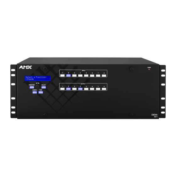
NetLinx Central Control Processor, standard front control panel, control software, or an external controller. For additional information on control options, see page 26. Control Dial Input Keys Power Indicator LED Output Keys Control Keys FIG. 2 Front view of an Enova DGX 32 enclosure Instruction Manual – Enova DGX 8/16/32 Digital Media Switchers... -
Page 16: Enova Dgx
The enclosure’s appearance, as viewed from the rear, will vary depending on the number and types of input, output, and expansion boards present. The Enova DGX 8 enclosure in FIG. 3 is fully loaded for 8x8 switching. The Enova DGX 16 enclosure in FIG. 4 is fully loaded for 16x16 switching. The Enova DGX 32 enclosure in FIG. - Page 17 * The two Control ports provide direct control of matrix switcher processing (they do not work on the same layer of control as the integrated Master, which uses the LAN 100/1000 and Program ports). Instruction Manual – Enova DGX 8/16/32 Digital Media Switchers...
-
Page 18: Power Supply Units
Enova DGX 32 - Indicator LEDs FIG. 7 Power supply receptacles for Enova DGX 8/16 (left) and Enova DGX 32 (right) Input and Output Boards A single enclosure can handle a combination of signals depending on the types of input and output boards. - Page 19 FIG. 8 DGX DXLink, DVI, and HDMI Input and Output Boards Enova DGX 8 enclosures have 4 horizontal I/O board slots (2 slots each for input and output boards with four connectors each), allowing for a maximum configuration of 8x8.
- Page 20 (for attaching destinations) are on the right. Input and output channel numbers correspond to the connectors and are located as follows: Enova DGX 8/16 – on the vertical numbering plate (metal strip) between the input and output connectors. ...
- Page 21 Serial Numbers The serial numbers are normally located on the rear of the enclosure on the left (for the Enova DGX 8, see FIG. 3 on page 16; for the Enova DGX 16, see FIG. 4 on page 16; and for the Enova DGX 32, see FIG. 5 on page 17).
-
Page 22: Enova Dgx 8 - General Specifications
• DGX Fiber HD-15 Transmitter and Receiver Modules * Use the Enova DGX Configuration Tool located at www.amx.com/enova to determine the power requirements of a configuration and whether any of the DXLink Transmitters or Receivers should be powered with the local power supply to maintain power supply redundancy in the Enova enclosure. -
Page 23: Enova Dgx 16 - General Specifications
• DGX Fiber HD-15 Transmitter and Receiver Modules * Use the Enova DGX Configuration Tool located at www.amx.com/enova to determine the power requirements of a configuration and whether any of the DXLink Transmitters or Receivers should be powered with the local power supply to maintain power supply redundancy in the Enova enclosure. -
Page 24: Enova Dgx 32 - General Specifications
• DGX Fiber HD-15 Transmitter and Receiver Modules * Use the Enova DGX Configuration Tool located at www.amx.com/enova to determine the power requirements of a configuration and whether any of the DXLink Transmitters or Receivers should be powered with the local power supply to maintain power supply redundancy in the Enova enclosure. -
Page 25: Enova Dgx - Netlinx And Control Specifications
100 Mbps when used with a total of 32 DXLink TXs and 32 DXLink RXs for an Enova DGX 32, 16 DXLink TXs and 16 DXLink RXs for an Enova DGX 16, and 8 DXLink TXs and 8 DXLink RXs for an Enova DGX 8. -
Page 26: Configuration Information And Control Options
Configuration Information and Control Options Switching Configuration Information The configuration file stored on the CPU contains routing and control information for the AMX Enova Routing System. Note: The configuration file is automatically generated by the system based on its hardware – input and output boards, expansion boards, front control panel, CPU, etc. -
Page 27: System Diagnostic Options
APDiagnostics is a software application that monitors and displays advanced diagnostic information about the behavior of the Enova DGX Switcher. This application is available at www.amx.com. APDiagnostics also works with AMX Matrix Switchers that are capable of reporting such data. For information on APDiagnostics, see Appendix C on page 181. -
Page 28: Installation And Setup
Before you unplug a fiber cable on an input board, disconnect the power on the DGX TX that is connected to the input. Before you unplug a fiber cable on an output board, disconnect the switch for that output connector. Instruction Manual – Enova DGX 8/16/32 Digital Media Switchers... -
Page 29: Site Recommendations
When installing equipment in a rack, distribute the weight to avoid uneven mechanical loading. Note that fully loaded, the Enova DGX 8 weighs approximately 35 pounds (15.9 kg), the Enova DGX 16 weighs approximately 55 pounds (24.95 kg), and the Enova DGX 32 weighs approximately 73 pounds (33.1 kg). -
Page 30: Unpacking
Collect all documentation. Note: Please save the original shipping container and packing materials. AMX is not responsible for damage caused by insufficient packing during return shipment to the factory. Shipping boxes are available; contact your AMX representative for details. -
Page 31: Options For System Setup With Dxlink
HD-15 TX SC Optical SC Optical DVI RX DVI TX SC Optical SC Optical HD-15 RX DVI TX SC Optical SC Optical DVI RX Instruction Manual – Enova DGX 8/16/32 Digital Media Switchers... -
Page 32: Enova Dgx
Note: In addition to the system setup options listed in the table on the previous page, optical signal flow between Enova DGX Switcher and Epica DGX 16/32/144 enclosures (from SC fiber connector to SC fiber connector) is supported. Contact your AMX representative for these and other system design possibilities. Rack Installation and System Setup Enova DGX Switchers can be mounted in a standard EIA 19 in. -
Page 33: Installation Procedure
Audio Insert/Extract Boards only – Remove the boards (see page 104) and set the DIP switches to either insert or extract audio (see page 104). This is the only mechanism for configuring the insert/extract functionality. Instruction Manual – Enova DGX 8/16/32 Digital Media Switchers... - Page 34 CPU backup with Micro SD memory card – page 61 Setting the Control Panel password – page 124 Defining local presets – page 177 Defining global presets – page 117 Instruction Manual – Enova DGX 8/16/32 Digital Media Switchers...
- Page 35 Enova DGX 8/16 Output board Input board Note: On the Enova DGX 8/16, the orientation of the cable management bar is reversed from input to output board. FIG. 16 Installation of cable management bars Insert and tighten the two screws at the end of the cable management bar (do not over tighten the screws).
-
Page 36: Attaching Video Input And Output Cables
Viewed from the rear of the enclosure, the input boards (for attaching sources) are on the left, and the output boards (for attaching destinations) are on the right. Enova DGX 8 – Enclosures have 4 horizontal board slots (2 slots each for the input and the output boards, ... -
Page 37: Attaching Audio Input And Output Wires
Calculating the power draw also helps determines how many DXLink Transmitters and Receivers can be powered via the switcher. Instruction Manual – Enova DGX 8/16/32 Digital Media Switchers... - Page 38 SC Optical Boards (see “System Setup with DGX Fiber Modules” on page 97 and the module’s documentation). Optional – Attach an external control device/system (see page 54). Instruction Manual – Enova DGX 8/16/32 Digital Media Switchers...
- Page 39 Plug power cords into both of the power receptacles on the enclosure. Enova DGX 8/16 power supplies FIG. 21 Attach power cables to both power receptacles (Enova DGX 8/16 shown) Enova DGX 32 power supplies FIG. 22 Attach power cables to both power receptacles (Enova DGX 32 shown) Plug the other end of each power cord into a power strip(s) that is turned off (we recommend using a 20 A circuit breaker on a 110 circuit for fully loaded enclosures).
-
Page 40: Redundant Power Supply (Rps)
If a power supply’s DC LED illuminates amber or red, contact technical support (see page 64). Caution: Do not remove a failed power supply until the replacement is ready to install, unless directed to do so by technical support. Instruction Manual – Enova DGX 8/16/32 Digital Media Switchers... -
Page 41: System Setup For Using The Integrated Netlinx Master
Caution: Be careful not to create a network (Ethernet) loop. To avoid doing so, see page 90. Program port connected to PC running NetLinx Studio FIG. 23 Enova DGX 32 connected via a LAN to two PCs (Program port is connected for initial set up) Instruction Manual – Enova DGX 8/16/32 Digital Media Switchers... -
Page 42: Program Port And Lan 100/1000 Port
Normal* Normal* disabled. Normal Integrated Master is functioning normally. 1 blink per second indicates indicates activity activity * Normal is typically off. However, this state may change depending on external inputs. Instruction Manual – Enova DGX 8/16/32 Digital Media Switchers... - Page 43 6 --------6 Orange No connection 7 --------7 Brown - White No connection 8 --------8 Brown FIG. 25 shows the connections for Ethernet RJ-45 connector/cable per T568A. FIG. 25 RJ-45 connections per T568A Instruction Manual – Enova DGX 8/16/32 Digital Media Switchers...
- Page 44 The LAN 100/1000 (RJ-45) port is an Ethernet link connector, handling Ethernet 10/100/1000 connections for 1000 Mbps (megabits per second), 100 Mbps, and 10 Mbps. This connection is compatible with most Ethernet based LANs. Instruction Manual – Enova DGX 8/16/32 Digital Media Switchers...
- Page 45 1319 or disable the ICSP over Ethernet completely from either Telnet or the Program port on the rear of the Enova DGX Switcher. This type of communication is used by various AMX products for communication among themselves (see page 147).
-
Page 46: System Setup Via Netlinx Studio
Important: Before the Program port can be used for communication, the appropriate FTDI driver used to create the virtual COM port must be installed on the PC per Step 3. At www.amx.com, a link for this driver can be found on the product’s web page, on the right under “Application Files.”... - Page 47 NetLinx Studio showing the Zero-Config tab and the IP address for a WebConsole interface Note: If you are not using NetLinx Studio and/or are using a third-party controller, contact your Network Administrator for the IP address. Instruction Manual – Enova DGX 8/16/32 Digital Media Switchers...
- Page 48 A List of Addresses section opens at the bottom of the dialog box. The list contains a series of previously entered IP Addresses/URLsand their associated names, all of which are stored within NetLinx Studio and are user-editable). TCP/IP Enova DGX 16 Click New. The New TCP/IP Setting dialog box opens. Instruction Manual – Enova DGX 8/16/32 Digital Media Switchers...
- Page 49 Click Change to alter your communication parameters and repeat the steps above. Important: The PC must be on the same subnet (e.g., 192.168.X.X) as the enclosure for the following procedure. Instruction Manual – Enova DGX 8/16/32 Digital Media Switchers...
- Page 50 XBar applet, and changing the proxy setting (see page 140). Complete information for the integrated NetLinx Master (NI-3100 Class Controller) is documented in the WebConsole & Programming Guide – NetLinx Integrated Controllers at www.amx.com. NetLinx WebConsole Troubleshooting Check the following: All power, signal, and link connections on all of the equipment.
-
Page 51: Executing A Test Switch
VM 0, unless you know the system was ordered with custom VMs. After the test switch has executed successfully: If necessary, adjust the image with DGX Configuration Software, which is available at www.amx.com. This software is used for configuring HDMI and DVI Boards (see page 153). - Page 52 Set the input on the source device to either a different input resolution or refresh rate (e.g., 1080p @ 50 Hz). Select a resolution and refresh rate from the PC’s graphic driver control panel and be sure to select “Maintain Display Scaling” as the “Scaling” option. Instruction Manual – Enova DGX 8/16/32 Digital Media Switchers...
- Page 53 Isolate source and destination devices using the modules to bypass the enclosure to check the twisted pair cable and overall signal path. Attempt the switch again. If the switch still does not work, contact technical support (see page 64). Instruction Manual – Enova DGX 8/16/32 Digital Media Switchers...
-
Page 54: Attaching An External Serial Controller
The communication protocols listed at the top of this page are used for these control options: XNNet Protocol Advanced programmers who want to design their own control programs can use AMX AutoPatch XNNet protocol. The XNNet API Communication Library (an interface library that supports C, Java, and Visual Basic with examples of the XNNet protocol in use) is available at www.amx.com. - Page 55 Stop Bits (see page 51). Flow Control None * For terminal emulation via the serial port, use the Terminal view in DGX Configuration Software (see page 168) or another terminal emulation program. Instruction Manual – Enova DGX 8/16/32 Digital Media Switchers...
- Page 56 To attach a PC to the USB (mini-B) port and establish a virtual COM port: Download the APBridge.inf file, which is located at www.amx.com (enter APBridge in the Search AMX.com field in the upper right-hand corner of the site). No user permissions are required.
- Page 57 In the Driver tab, select the Update Driver button. Driver tab Update Driver button * The Device Manager may have a different location depending on the operating system and theme selected. Instruction Manual – Enova DGX 8/16/32 Digital Media Switchers...
- Page 58 If the port does not specify a COM number, right-click the AutoPatch USB Bridge, select Properties, and complete all remaining steps. COM port number (if not displayed, complete all remaining steps) Instruction Manual – Enova DGX 8/16/32 Digital Media Switchers...
- Page 59 Important: You must identify the virtual COM port assigned to the USB connector to enable communication between the Control PC and the switcher. Set up and run the desired application: AMX Controller – For control programming information, see the instruction manual for the specific interface.
- Page 60 FIG. 34 Power-up splash screen in Terminal view in DGX Configuration Software Note: AMX reserves the right to add to the contents of the splash screen at any time, without notice. BCS (Basic Control Structure) Tunneling Access Support The following instructions are for establishing a terminal emulation program connection for tunneling BCS commands via TCP/IP over the LAN 100/1000 port.
-
Page 61: Cpu Backup With Micro Sd Memory Card
These cards are considered “removable memory.” Firmware updates are periodic and necessary for bug fixes and feature additions. * Having a physical means to update the firmware is a plus, as a Micro SD memory card can be shipped into strict security installations. Instruction Manual – Enova DGX 8/16/32 Digital Media Switchers... - Page 62 For terminal emulation, use the Terminal view in DGX Configuration Software (see page 168) or another terminal emulation program. Note: For additional information on establishing serial communication between the enclosure and a PC, see page 54. Instruction Manual – Enova DGX 8/16/32 Digital Media Switchers...
- Page 63 Set the COM port and baud rate (the default baud rate for the Enova DGX is 9600). Click Connect.* Enter ~sysb! (back up settings). Enter ~sysr! (restore settings). Click Send. * When done in the Terminal view, be sure to click the Disconnect button. Instruction Manual – Enova DGX 8/16/32 Digital Media Switchers...
-
Page 64: Technical Support
If this manual has not satisfactorily answered your questions regarding the Enova DGX Switcher or the system is not operating as expected, please contact your AMX representative or technical support. Have the serial numbers for your system and any applicable AMX accessory devices ready (the numbers are normally located on the rear of the enclosure or accessory devices). -
Page 65: Enova Dgx Hdmi Boards
Enova DGX HDMI Input and Output Boards (Enova DGX 32 shown) Enova DGX 8 Enova DGX 8 enclosures are built to hold up to four DGX HDMI Boards with four inputs or outputs per board. Each enclosure holds a maximum of two input and two output boards, accommodating connector configurations up to a maximum of 8x8, as well as three subsets (i.e., 4x4, 4x8, or 8x4). -
Page 66: Enova Dgx Hdmi Boards - Specifications
• 2K formats are only compatible with DVI and HDMI Input/Output Boards and require the output scaler to be set in Bypass mode AMX reserves the right to modify its products and their specifications without notice. Instruction Manual – Enova DGX 8/16/32 Digital Media Switchers... - Page 67 4 HDMI Type A female ports * When used with DXLink Output Boards and the RX Scaler is in Bypass mode. AMX reserves the right to modify its products and their specifications without notice. Instruction Manual – Enova DGX 8/16/32 Digital Media Switchers...
- Page 68 60 Hz, 67 Hz, 72 Hz, 75 Hz AMX reserves the right to modify its products and their specifications without notice. Tip: If you are experiencing audio problems, it may be because you are trying to pass Dolby or DTS or high PCM frequency rates and the destination device does not support them.
- Page 69 Important: For information on troubleshooting audio, including a table on “Audio Format Support on Enova DGX Boards,” see page 73. AMX reserves the right to modify its products and their specifications without notice. Instruction Manual – Enova DGX 8/16/32 Digital Media Switchers...
-
Page 70: Attaching Cables
(for attaching destinations) are on the right. Enova DGX 8/16 – Input and output channel numbers correspond to the connectors and are located between the input and output boards. For inputs, numbering is consecutive from left to right on each board from the top board to the bottom board;... - Page 71 HDMI output on the switcher can handle is finite, the number of sinks can be unlimited if using AMX devices that support InstaGate Pro Technology. * In some cases, source devices will always enforce HDCP even if the content is not protected. In those cases, when the source device sees that its output is connected to the input of the Enova DGX HDMI board (or another HDCP compliant sink), the source device will always enforce and encrypt the HDMI signal that it sends.
-
Page 72: Instagate Pro® Technology
Although InstaGate Pro significantly reduces the latency associated with HDCP authentication, it cannot reduce the inherent lag time of a device as it syncs up to the newly switched video image. Instruction Manual – Enova DGX 8/16/32 Digital Media Switchers... -
Page 73: Troubleshooting Audio
EDID setting. Checking for Support The easiest way to check whether or not a destination supports a source device’s audio signal is to connect the source directly to the destination. Instruction Manual – Enova DGX 8/16/32 Digital Media Switchers... - Page 74 Use DGX Configuration Software to write an EDID to the HDMI input on the Enova DGX Switcher that best represents the downstream destination. Check the AutoPatch_EDID_Library file at www.amx.com (search for EDID Library) to determine if one of the custom EDID files meets your needs. (The custom EDID files are variants of base EDIDs.) For additional information on custom EDID files, see page 165.
-
Page 75: Enova Dgx Dvi Boards
Enova DGX 8 Enova DGX 8 enclosures hold up to four DVI Boards with four inputs or outputs per board. Each enclosure holds a maximum of two input and two output boards, accommodating connector configurations up to a maximum of 8x8, as well as three subsets (i.e., 4x4, 4x8, or 8x4). - Page 76 Note: HDMI-to-DVI or DVI- to-HDMI conversion requires an applicable conversion cable. Audio Support on DVI Boards When DVI Boards are set up to support HDMI signals, the audio information in the HDMI Board chapter applies (see page 73). Instruction Manual – Enova DGX 8/16/32 Digital Media Switchers...
-
Page 77: Enova Dgx Dvi Boards - Specifications
Note: Interlaced and progressive video are supported into the HDMI Input Board; progressive video is only supported out of the HDMI Output Board, unless in non-scaling bypass mode. AMX reserves the right to modify its products and their specifications without notice. Instruction Manual – Enova DGX 8/16/32 Digital Media Switchers... - Page 78 640x480 60 Hz, 67 Hz, 72 Hz, 75 Hz AMX reserves the right to modify its products and their specifications without notice. Important: For information on troubleshooting audio, including a table on “Audio Format Support on Enova DGX Boards,” see page 73.
-
Page 79: Attaching Cables
(for attaching destinations) are on the right. Enova DGX 8/16 – Input and output channel numbers correspond to the connectors and are located between the input and output boards. For inputs, numbering is consecutive from left to right on each board from the top board to the bottom one;... -
Page 80: Enova Dgx Dxlink™ Twisted Pair Boards
Transmitters and Receivers or other AMX DXLink™ signal management solutions. Enova DGX 8 Enova DGX 8 enclosures are built to hold up to four DXLink Boards with four RJ-45 inputs or outputs per board. Each enclosure holds a maximum of two input and two output boards, accommodating connector configurations up to a maximum of 8x8, as well as three subsets (i.e., 4x4, 4x8, or 8x4). -
Page 81: Hdcp Compliance
DXLink Input Board’s input connection. With InstaGate Pro Technology, when a source requires HDCP encrypted content, the inputs and compliant downstream devices are automatically authenticated. Instruction Manual – Enova DGX 8/16/32 Digital Media Switchers... -
Page 82: Dxlink™ Twisted Pair Boards - Specifications
^^ Input signal support for YCbCr 4:4:4 and 4:2:2, output color-space is converted to RGB 4:4:4. * When used with DXLink Output Boards and the RX Scaler is in Bypass mode. AMX reserves the right to modify its products and their specifications without notice. Instruction Manual – Enova DGX 8/16/32 Digital Media Switchers... - Page 83 *** “Common building” is defined as: Where the walls of the structure(s) are physically connected and the structure(s) share a single ground reference. AMX reserves the right to modify its products and their specifications without notice. Instruction Manual – Enova DGX 8/16/32 Digital Media Switchers...
- Page 84 In either of these cases, re-programming the EDID may help resolve the problem. AMX reserves the right to modify its products and their specifications without notice. Instruction Manual – Enova DGX 8/16/32 Digital Media Switchers...
- Page 85 Important: For information on troubleshooting audio, including a table on “Audio Format Support on Enova DGX Boards,” see page 73. AMX reserves the right to modify its products and their specifications without notice. Instruction Manual – Enova DGX 8/16/32 Digital Media Switchers...
-
Page 86: System Setup With Dxlink™ Transmitters And Receivers
Enova DGX DXLink™ Twisted Pair Boards System Setup with DXLink™ Transmitters and Receivers DXLink™ Twisted Pair Input and Output Boards must be used in conjunction with AMX DXLink™ Transmitters and Receivers or other AMX DXLink™ signal management solutions. This combination creates an end-to-end extender solution for transmission of HDMI (or DVI via adapter cable) over twisted pair cable. - Page 87 PC for control and the destination monitor can be seen simultaneously if adjustments are necessary. Adjustments can be made using DGX Configuration Software (see page 153). Caution: Be careful not to create a network (Ethernet) loop. To avoid doing so, see page 90. Instruction Manual – Enova DGX 8/16/32 Digital Media Switchers...
- Page 88 Do not use the local DC power jack on the Module (even if the local power adapter is off). *AMX supports the use of DXLink power injector PDXL-2 (FG1090-170) and PS-POE-AT-TC (FG423-84); other power injectors may potentially damage the DXLink equipment.
-
Page 89: Power Budget Planning For Systems With Dxlink Boards
DXLink Transmitters and Receivers to be powered via the switcher, and the calculator shows the resulting power draw. The Enova DGX Configuration Tool is located at www.amx.com/enova. If more DXLink units are required than the switcher can support while maintaining redundancy, they must be powered using the provided desktop power supplies (which must not be altered in any way) or a DXLink power injector;... -
Page 90: Connecting Switching Systems With Dxlink Connectors
DXLink port will automatically disable all Ethernet, power, and control on that connection port so that the only things passed down the DXLink line are the video and audio signals. When connecting switching systems via DXLink ports, AMX recommends no more than 3 switcher throughputs.* Network loops must be avoided (see below). -
Page 91: Attaching Cables
(for attaching destinations) are on the right. Enova DGX 8/16 – Input and output channel numbers correspond to the connectors and are located between the input and output boards. For inputs, numbering is consecutive from left to right on each board from the top board to the bottom one;... - Page 92 On – Speed status is 100 Mbps Off – Speed status is 10 Mbps FIG. 48 DXLink connector LEDs (left Enova DGX 32 board orientation; right Enova DGX 8/16 Output Board orientation) Instruction Manual – Enova DGX 8/16/32 Digital Media Switchers...
-
Page 93: Integrating Dxlink Txs And Rxs In Netlinx Studio
AV with NetLinx control of TX/RX unit and serial/IR ports, plus Ethernet pass-through to networked device* * Connect the ICS LAN 10/100 port of the DXLink unit to the network device (e.g., laptop, IP controlled projector, AMX ICSLan EXB device). -
Page 94: Serial Data Transfer And Ir Flow Control
Media Switcher is used with DXLink Modules in Endpoint Mode. The switcher has an integrated NetLinx Central Control Processor which provides native AMX control at each remote location fed by a DXLink Transmitter or Receiver. Control is sent over twisted pair cable (via the DXLink ports). -
Page 95: Epica Dgx Sc Optical Boards
Enova DGX 8 Enova DGX 8 enclosures can hold up to four Epica DGX SC Optical Boards. Each enclosure holds a maximum of two input and two output boards, accommodating connector configurations up to a maximum of 8x8, as well as three subsets (i.e., 4x4, 4x8, or 8x4). -
Page 96: Epica Dgx Sc Optical Boards - Specifications
*** 3000 ft. cable requires 50/125 m OM2 class low loss fiber cable. Important: These boards are compatible only with other AMX products that support the DGX Single Fiber Technology. They are not compatible with third-party optical distribution amplifiers or multimode to single mode converters. -
Page 97: System Setup With Dgx Fiber Modules
System Setup with DGX Fiber Modules Epica DGX SC Optical Input and Output Boards must be used in conjunction with AMX DGX Fiber TX and RX Modules. Compatible DGX Fiber Modules are listed on page 96. System setup options are listed in a table on page 31. -
Page 98: Safety Recommendations For Laser Products
(for attaching destinations) are on the right. Enova DGX 8/16 – Input and output channel numbers correspond to the connectors and are located between the input and output boards. For inputs, numbering is consecutive from left to right on each board from the top board to the bottom one;... - Page 99 Fasten cables onto input and output connectors (shown with cable management bar) 5. Tie the SC fiber cable to the cable management bar far enough below the connector to allow for the manufacturer’s recommended bend radius. The bend radius for AMX SC terminated fiber cables is 2 inches (5 cm).
-
Page 100: Enova Dgx Audio Insert/Extract Board
AIE Input 1 is embedded on the HDMI signal. Note: Enova DGX 8 only – Depending on location, AIE Board connectors 1-8 correspond to standard input or output connectors 1-8. Connectors 9-16 are inoperable. Instruction Manual – Enova DGX 8/16/32 Digital Media Switchers... -
Page 101: Enova Dgx Audio Insert/Extract Board - Specifications
L-PCM formats will pass incomplete audio if extracted (only 2 of the multiple channels will be extracted). All other audio formats will be muted at the extraction port. AMX reserves the right to modify its products and their specifications without notice. Instruction Manual – Enova DGX 8/16/32 Digital Media Switchers... -
Page 102: System Examples
Source device Destination device F L T F L T Audio connector set to “Insert” Auxiliary audio system Analog stereo audio FIG. 56 Audio inserted onto HDMI output signal Instruction Manual – Enova DGX 8/16/32 Digital Media Switchers... - Page 103 Note: When audio is routed through a separate Audio Matrix Switcher, the audio can be inserted back into the original system on multiple audio insert/extract connectors. Important: When audio is “extracted” from an HDMI signal, the audio also remains intact as embedded audio on the HDMI signal. Instruction Manual – Enova DGX 8/16/32 Digital Media Switchers...
-
Page 104: Setting Audio Connectors To Insert Or Extract
Remove screw, push board extractor handle down, then pull board straight out (Enova DGX 32 shown) 4. Set the Dip switches according to the information on the following page, and then reinstall the board according to the directions on page 106. Instruction Manual – Enova DGX 8/16/32 Digital Media Switchers... -
Page 105: Setting The Dip Switches
To insert audio, flip right. The AIE connector will insert the connected audio signal onto the corresponding standard input or output connector’s signal. When shipped from the factory, the DIP switches are set to “Enable” and “Extract.” Instruction Manual – Enova DGX 8/16/32 Digital Media Switchers... -
Page 106: Reinstalling The Aie Board
Enova DGX 32 and between the input and output slots on an Enova DGX 8/16.) An AIE Board can only be installed in an I/O expansion board slot. -
Page 107: Attaching Wires
DGX 16. Be sure to note the labeling for the wiring on the “R” (right channel) and the “L” (left channel) wires in FIG. 62. Enova DGX 8/16 only – the orientation of audio Insert/Extract Board in the right AIE slot places the number ... -
Page 108: Testing/Checking The Insert/Extract Functionality
AIE 1 works with standard Input 1, AIE 2 works with standard Input 2, etc. Enova DGX 8 only – Depending on location, AIE Board connectors 1-8 correspond to standard input or ... -
Page 109: Control Panel Operation
The Cancel Key cannot undo a completed operation, e.g., an operation followed by the pressing of the Take Key. If the Cancel Key flashes, an error has occurred; a flashing Cancel Key must be pressed before continuing. Instruction Manual – Enova DGX 8/16/32 Digital Media Switchers... - Page 110 (inputs not available) Blue keys White keys Blue keys (outputs available) (outputs available) (outputs selected) FIG. 66 Example of key states during Change Mode (Control Panel on an Enova DGX 32) Instruction Manual – Enova DGX 8/16/32 Digital Media Switchers...
- Page 111 Selecting Local Preset accesses the list of local presets that can be executed (see page 119). Local Preset will only appear as an option on the Function menu if local presets have been defined in XNConnect configuration software for the selected virtual matrix. Instruction Manual – Enova DGX 8/16/32 Digital Media Switchers...
- Page 112 Take Key. Labeling Input and Output Keys Each Enova DGX Switcher ships with a kit for custom labeling. To order additional kits, contact your AMX representative. The Control Panel Label Kit (KA1056-01) includes: Perforated card stock sheets –...
-
Page 113: Executing Switches
1. Press the Function Key. The Function menu appears. 2. Press the Select Key to choose Change. The system is in Change Mode (the available Input and Output Keys turn blue). Current virtual matrix Instruction Manual – Enova DGX 8/16/32 Digital Media Switchers... -
Page 114: Changing The Virtual Matrix
5. Press the Select Key to enter your selection. The display returns to the top of the V.Matrix submenu. VM 2 “Custom” becomes the new virtual matrix used for all operations. Newly selected virtual matrix Instruction Manual – Enova DGX 8/16/32 Digital Media Switchers... -
Page 115: Disconnecting Switches
The system is in Disconnect Mode (all the available Input and Output Keys turn blue). 4. Press Input Keys 1 and 3 and Output Key 9. The keys turn white indicating that they are selected. Virtual matrix Instruction Manual – Enova DGX 8/16/32 Digital Media Switchers... -
Page 116: Verifying Signal Status
The selected Output Key turns white, and if an Input Key routed to it, that key also turns white. 5. Select another signal to verify. Press the Function Key to return to the Function menu. Instruction Manual – Enova DGX 8/16/32 Digital Media Switchers... -
Page 117: Defining And Executing Global Presets
The Global Preset submenu appears. 5. Scroll with the Control Dial to Define Global. Press the Select Key. The Define Global list appears. 6. Scroll with the Control Dial until Global Preset 3 appears. Instruction Manual – Enova DGX 8/16/32 Digital Media Switchers... -
Page 118: Executing Local Presets
Local presets are not programmed (defined) at the factory. To program them, use XNConnect configuration software (see page 177) or contact your AMX representative (for contact information, see page 64). Once the local presets have been defined as part of the configuration file, the new file must be loaded to the system’s CPU (see page 179) and reloaded to the Control Panel (see page 123). -
Page 119: Locking And Unlocking
Caution: We strongly recommend recording passwords in a secure place; Enova DGX Switchers cannot retrieve a lost password. If the password is lost while the system is locked, contact technical support (see page 64). Instruction Manual – Enova DGX 8/16/32 Digital Media Switchers... - Page 120 You must enter the password within ten (10) seconds. 2. Press the Input Keys in the following order: 1, 2, 3, 4, 5 (default password). The panel unlocks and returns to the Function menu. Instruction Manual – Enova DGX 8/16/32 Digital Media Switchers...
-
Page 121: Setup Options
5. Scroll with the Control Dial to see additional Software Version information. 6. Press the Cancel Key to return to the Setup Options submenu. Press the Function Key to return to the Function menu. Instruction Manual – Enova DGX 8/16/32 Digital Media Switchers... - Page 122 Change the virtual matrix (see page 114) to immediately execute operations on the new default virtual matrix without cycling power. (The next time power is cycled, VM 2 will be implemented as the default virtual matrix.) Instruction Manual – Enova DGX 8/16/32 Digital Media Switchers...
- Page 123 The configuration file reloads to the Control Panel and the display returns to the top of the Setup Options submenu. 6. Press the Function Key to return to the Function menu. Instruction Manual – Enova DGX 8/16/32 Digital Media Switchers...
-
Page 124: Setting The Password
5. The LCD displays the prompt Enter New PWD. Using any combination of the illuminated keys, input the new password. (To change any entries, press the Cancel Key – restarting the process – and reenter from the start.) Instruction Manual – Enova DGX 8/16/32 Digital Media Switchers... - Page 125 Enter New PWD screen and repeat Steps 5 and 6. 7. When the new password is successfully reset, press the Cancel Key to return to the Setup Options submenu. Press the Function Key to return to the Function menu. Instruction Manual – Enova DGX 8/16/32 Digital Media Switchers...
-
Page 126: System Error Codes And Troubleshooting
(e.g., a global preset number that does not correspond to a defined global preset). If the error code persists after correcting and resending the command, contact technical support (see page 64). Instruction Manual – Enova DGX 8/16/32 Digital Media Switchers... -
Page 127: Netlinx Integrated Control
WebConsole & Programming Guide – NetLinx Integrated Controllers at www.amx.com. In the WebConsole, the Device drop-down menu lists the “System Number,” the “NI Master” (NetLinx Master) which is integrated into the Digital Media Switcher, and the switcher: Enova DGX 8, Enova DGX 16, or Enova DGX 32 (FIG. 68). -
Page 128: Opening The Netlinx Webconsole
NetLinx® Integrated Control The WebConsole & Programming Guide – NetLinx Integrated Controllers at www.amx.com provides information on the following: D:P:S specification Navigation of the WebConsole user interface Basic configuration of the system Firmware upgrades Options on the WebConsole pages for the System, Master, and devices ... -
Page 129: Getting A Dhcp Ip Address
Important: Any time you click “Reboot” from any page in the WebConsole, the server reboots. The reboot updates information between the Enova DGX Master and the server. The Enova DGX Switcher itself does not reboot. Instruction Manual – Enova DGX 8/16/32 Digital Media Switchers... -
Page 130: Setting A Static Ip Address
Enova DGX Master and the server. The Enova DGX Switcher itself does not reboot. Note: A static IP address can also be set without using a DHCP server by following the directions on the next page. Instruction Manual – Enova DGX 8/16/32 Digital Media Switchers... - Page 131 Settings written. Device must be rebooted to enable new settings. >reboot 0:1:0 Important: The reboot updates information between the Enova DGX Master and the server. The Enova DGX Switcher itself does not reboot. Instruction Manual – Enova DGX 8/16/32 Digital Media Switchers...
-
Page 132: Enova Dgx Webconsole Interface
The icsp Device Config tab opens to the Enova DGX 16 (8 or 32) Device Config page (FIG. 72). On the left of the page is a field for editing the device number for the Enova DGX 8/16/32. On the right under Current Application Information, the version for the interface is displayed. -
Page 133: Upgrade - Upgrade Log - Enova Dgx 16 Upgrade Log
When the upgrade is complete, remember to change back to the original cache settings. If you need instructions, see page 146. FIG. 74 Enova DGX 16 Upgrade Status page Instruction Manual – Enova DGX 8/16/32 Digital Media Switchers... -
Page 134: Upgrade - Upgrade Config - Enova Dgx 16 Upgrade Config
IP Control Drop-Down Menu (4 Options) The IP Control tab opens a drop-down menu with four options: Home, Configuration, Preferences, and Controller (the XBar Controller). FIG. 76 IP Control tab drop-down menu Instruction Manual – Enova DGX 8/16/32 Digital Media Switchers... -
Page 135: Ip Control - Configuration - Enova Dgx 16 Configuration
The BCS Tunnel Port Number can be edited (available numbers are 1025-65535, except 1319). (The Serial Port Baud Rate field is non-editable.) FIG. 78 Enova DGX 16 Configuration page (logged in) Instruction Manual – Enova DGX 8/16/32 Digital Media Switchers... -
Page 136: Ip Control - Preferences - Enova Dgx 16 Preferences
* If you want the default VM for display in the XBar to be the first virtual matrix discovered during bootup regardless of its number, enter a value of -1; otherwise, enter the specific VM number. Instruction Manual – Enova DGX 8/16/32 Digital Media Switchers... -
Page 137: Ip Control - Controller - Xbar Controller
VM may affect the routing state on the other VMs. Note: Multiple independent AMX Routing Systems (each with its own server connection) can be controlled from a single PC. Each WebConsole can be assigned a unique IP address. The individual addresses can then be entered as needed in the browser. - Page 138 (Basic Control Structure) command and indicates when the command is successfully executed. * For complete information on BCS commands, see the Instruction Manual – BCS Basic Control Structure Protocol at www.amx.com. Instruction Manual – Enova DGX 8/16/32 Digital Media Switchers...
- Page 139 Status of the update is shown in the Operation Progress status bar. 3. Close the VM Selection Pad when the update is complete. The most current routing state of the crosspoints is displayed. Instruction Manual – Enova DGX 8/16/32 Digital Media Switchers...
-
Page 140: Firmware Upgrade & Info For Network Admin
Before attempting to upgrade the firmware, you must have the appropriate KIT files. Go to www.amx.com and download the latest firmware files for the system from the Enova DGX 8, Enova DGX 16, or Enova DGX 32 Enclosure page. -
Page 141: Sending Firmware (*.Kit) Files To The Enova Dgx
Enova DGX 8/16/32 Switcher – Default Device ID 5002 Important: Any programs using the USB connection to the Enova DGX 8/16/32 must be halted prior to the upgrade process being initiated to avoid breaking the USB link to the PC. - Page 142 * During normal operation a blinking red Status LED is cause for concern (indicates the system is in IOS mode). However, during firmware upgrade the system may be in IOS mode for a period of time. Instruction Manual – Enova DGX 8/16/32 Digital Media Switchers...
-
Page 143: Embedding The Xbar Applet
<param name = "InitialVM" value = "0"> <param name = "VMLockDown" value = "locked"> <param name = "AllowGain" value = "true"> <param name = "AllowVolume" value = "true"> </APPLET> </BODY> </HTML> Instruction Manual – Enova DGX 8/16/32 Digital Media Switchers... -
Page 144: Changing The Proxy Setting
The following instructions apply to Internet Explorer. To change these settings in another browser, consult its Help file. To add an exception to the proxy setting information: 1. From the Tools menu on the browser, select Internet Options. The Internet Options dialog box opens. Instruction Manual – Enova DGX 8/16/32 Digital Media Switchers... - Page 145 5. In the Exceptions field, enter the appropriate IP address for the Enova DGX Switcher (see page 47). 6. Click OK to exit each of the dialog boxes used in these steps. Instruction Manual – Enova DGX 8/16/32 Digital Media Switchers...
-
Page 146: Checking Cache Settings In A Web Browser
4. Under “Check for new versions of stored pages,” click the “Every time I visit the webpage” radio button. 5. Click OK to exit. 6. When the upgrade is complete, repeat steps to restore original setting. Instruction Manual – Enova DGX 8/16/32 Digital Media Switchers... -
Page 147: Integrated Master - Netlinx Programming
Other commands are rejected with a notice being sent back to the NetLinx Master. This port requires a wait-for-response (e.g., wait for the T or wait for the full command to be returned with a T in the response). Instruction Manual – Enova DGX 8/16/32 Digital Media Switchers... -
Page 148: Digital Media Switchers: Send_Commands
To distinguish the functionality of signal input and output ports from the overlapped device port numbers, the signal input and output numbers are part of the command’s action. Signal inputs and outputs range from 1-8 (Enova DGX 8), 1-16 (Enova DGX 16), and 1-32 (Enova DGX 32) for video.* * Because the Audio Insert/Extract Board can be set to insert/extract audio into/out of video inputs or outputs, the audio signals from these boards switch in conjunction with the corresponding video signals. - Page 149 • L# = level number (virtual matrix number) either 0 or 1 (both switch video along with any embedded audio) • I# = input port number (for Enova DGX 8: 1-8 = Inputs 1-8, Enova DGX 16: 1-16 = Inputs 1-16, Enova DGX 32: 1-32 = Inputs 1-32) •...
- Page 150 • I# = input port number (for Enova DGX 8: 1-8 = Inputs 1-8, Enova DGX 16: 1-16 = Inputs 1-16, Enova DGX 32: 1-32 = Inputs 1-32) • O# = output port number (for Enova DGX 8: 1-8 = Outputs 1-8,...
- Page 151 L<L#>.) any embedded audio) • I# = input port number (for Enova DGX 8: 1-8 = Inputs 1-8, Enova DGX 16: 1-16 = Inputs 1-16, Enova DGX 32: 1-32 = Inputs 1-32) • O# = output port number (for Enova DGX 8: 1-8 = Outputs 1-8,...
- Page 152 For complete information on BCS commands supported by Enova DGX Switchers, see the product specific information in the Instruction Manual – BCS Basic Control Structure Protocol at www.amx.com. Instruction Manual – Enova DGX 8/16/32 Digital Media Switchers...
-
Page 153: Appendix A - Dgx Configuration Software
EDID requirements. AMX provides a single program, DGX Configuration Software, to handle a variety of tasks for the HDMI, DVI, and DXLink Boards. This program provides functionality for the following: Scaler Mode –... - Page 154 For information on the tabbed views see: Scaler Mode – page 155 Scaler Override – page 157 EDID Programmer – page 162 HDCP Settings – page 167 Terminal – page 168 Instruction Manual – Enova DGX 8/16/32 Digital Media Switchers...
-
Page 155: Scaler Mode View
In this mode, the system ignores the EDID data being received from a display up to 1920x1200. When you select and set the Manual (override) scaler mode, select the Scaler Override tab to configure the resolution (see page 157). Instruction Manual – Enova DGX 8/16/32 Digital Media Switchers... - Page 156 * When selecting multiple outputs: either select consecutive outputs by holding down the Shift key and clicking the first and last output or select nonconsecutive outputs by holding down the Control key and clicking on each output. Instruction Manual – Enova DGX 8/16/32 Digital Media Switchers...
-
Page 157: Scaler Override View
720x400 @ 70 Hz, 720x400 @ 88 Hz, 640x480 @ 67 Hz, 832x624 @ 75 Hz, and 1152x870 @ 75 Hz. These timings can be entered in the program as custom resolutions. Instruction Manual – Enova DGX 8/16/32 Digital Media Switchers... - Page 158 Time Saving Tip: When a number of outputs are connected to destination devices of the same type, the Get Current Timing button can be used to retrieve the settings from a single output connector. Save those settings to a file and then load the settings to the other outputs. Instruction Manual – Enova DGX 8/16/32 Digital Media Switchers...
- Page 159 6. Click Save to store the currently displayed settings to the connector(s) and persist them in memory. (If the settings have been changed since clicking Apply, the newest settings will be saved.) Instruction Manual – Enova DGX 8/16/32 Digital Media Switchers...
- Page 160 7. Click Save to store the currently displayed settings to the connector and persist them in memory. (If the settings have been changed since clicking Apply, the newest settings will be saved.) Instruction Manual – Enova DGX 8/16/32 Digital Media Switchers...
- Page 161 Note: Down scaling to 800x600 – When using the program to scale from 1280x1024 down to 800x600, occasionally the video changes to a solid color screen and needs to be reset to restore the image. Auto Scaling is recommended when possible. Instruction Manual – Enova DGX 8/16/32 Digital Media Switchers...
-
Page 162: Edid Programmer View
In cases where local DVI or HDMI outputs are used and a resolution incompatibility exists (or if a source device needs a specific resolution), the DGX DVI and DGX HDMI Input Boards have the ability to update the EDID emulation file (by updating each input’s EEPROM chip) which comes pre-loaded with an AMX AutoPatch EDID set. - Page 163 Option 2: Install the DGX Configuration Software and open the EDID Programmer view. Check the AutoPatch_EDID_Library file at www.amx.com (search for EDID Library) to determine if one of the custom EDID files meets the needs of the equipment. (The custom EDID files are variants of base EDIDs.) Open and write the custom EDID file to the DXLink, DVI, or HDMI input connector.
- Page 164 DGX Configuration Software functionality. From the Utilities menu, select Launch EDID Programmer Classic to open a program that will work with the system; follow the directions in its Help file. Instruction Manual – Enova DGX 8/16/32 Digital Media Switchers...
- Page 165 Both of the default EDID files support basic audio only (L-PCM 32 k, 44.1 k, and 48 k). The files in the following two tables are located in the AutoPatch_EDID_Library file at www.amx.com (search for EDID Library). Files using 1080p (VIC 16) as the preferred and native video resolution:...
-
Page 166: Device Between Hdmi Output Board And Monitor
12. Click Save to store the currently displayed settings to the connector and persist them in memory. (If the settings have been changed since clicking Apply, the newest settings will be saved.) Instruction Manual – Enova DGX 8/16/32 Digital Media Switchers... -
Page 167: Hdcp Settings View
Note: To enable or disable HDCP support over the DXLink line, send the appropriate SEND_COMMAND ) to the DXLink Transmitter. For details, see the “NetLinx Programming” chapter of HDCP-<ENABLE|DISABLE> the “Instruction Manual – DXLink™ Twisted Pair Transmitters/Receiver.” Instruction Manual – Enova DGX 8/16/32 Digital Media Switchers... -
Page 168: Terminal View
Auxiliary BCS Commands Auxiliary commands are also included in the Instruction Manual – BCS Basic Control Structure Protocol at www.amx.com. The two most common auxiliary commands are: ~app! (to cause a warm reboot) and ~scr! (to view a splash screen). - Page 169 1. From the File menu, select Save to File (select location, enter file name, and click Save). The file format defaults to a .txt file. Tip: Select and copy any or all of the data in the terminal window and then paste it into another program. Instruction Manual – Enova DGX 8/16/32 Digital Media Switchers...
-
Page 170: Appendix B - Managing Configuration Files
Note: If you use the advanced feature of creating a new virtual matrix (VM), be aware that the Control Panel for the Enova DGX Switcher supports a maximum of two digits for virtual matrix numbers. Instruction Manual – Enova DGX 8/16/32 Digital Media Switchers... -
Page 171: Xnconnect Overview
XNConnect can be used to modify a system’s configuration information which contains routing and control information. XNConnect is available at www.amx.com. Configuration file modifications include basic tasks, such as creating local presets and setting the Control Panel password. -
Page 172: Installing And Launching Xnconnect
Use this software only if you need to customize or change the configuration information from the original specification. Important: Even if XNConnect is already on your PC, install the latest version from www.amx.com. We strongly recommend uninstalling the old version of XNConnect before installing a new version. -
Page 173: Discovering A System
(We recommend making a duplicate copy every time the file is modified.) The discovered configuration file is ready to be modified. Whenever changes are made, the new file must be loaded onto the system to implement the changes (see page 179). Instruction Manual – Enova DGX 8/16/32 Digital Media Switchers... -
Page 174: Opening An .Xcl Configuration File
(see page 179). Important: Even if XNConnect is already on your PC, install the newest version from www.amx.com. We strongly recommend uninstalling the old version of XNConnect before installing the new version. -
Page 175: Navigating The Interface
Hardware tab Virtual Matrices tab Highlighted device Properties of highlighted device Components of the primary device Primary device Communication settings Device firmware version FIG. 99 XNConnect interface with Hardware tab selected Instruction Manual – Enova DGX 8/16/32 Digital Media Switchers... -
Page 176: Modifying An .Xcl Configuration File
7. From the File menu, select Save As and save an .xcl file with a new name to the PC. (We strongly recommend making a duplicate copy every time the file is modified.) Instruction Manual – Enova DGX 8/16/32 Digital Media Switchers... - Page 177 3. Optional – Enter a different preset number (local presets do not need to be numbered sequentially). 4. Enter a name for the new preset. 5. Click OK. The Modify Preset dialog box opens. Instruction Manual – Enova DGX 8/16/32 Digital Media Switchers...
- Page 178 (We strongly recommend making a duplicate copy every time the file is modified.) 14. Reload the .xcl file from the CPU to the Control Panel according to the directions on page 123. Instruction Manual – Enova DGX 8/16/32 Digital Media Switchers...
-
Page 179: Loading An .Xcl Configuration File
Configure > Reboot All Devices). 9. If local presets were created and loaded to the CPU – Reload the .xcl file from the CPU to the Control Panel according to the directions on page 123. Instruction Manual – Enova DGX 8/16/32 Digital Media Switchers... - Page 180 6. Enter: ~def! to restore the configuration. 7. Wait for a “ ” to be returned (may take several seconds). 8. Click Send. * When done in the Terminal view, be sure to click the Disconnect button. Instruction Manual – Enova DGX 8/16/32 Digital Media Switchers...
-
Page 181: Appendix C - Apdiagnostics
APDiagnostics Overview APDiagnostics is a software application that monitors and displays advanced diagnostic information about the Enova DGX Digital Media Switcher. (APDiagnostics also works with AMX Matrix Switchers that are capable of reporting such data.) This application is available at www.amx.com. - Page 182 13. Select the Serial Port tab and set the Comm ID and baud rate (9600). 14. Click Accept. Note: DGX_SHELL commands are another resource for accessing diagnostic information for a system (see page 212). Instruction Manual – Enova DGX 8/16/32 Digital Media Switchers...
-
Page 183: Modes
Main screen in Emulation mode (the Comm menu option is not available in this mode) Note: Custom window colors can be applied to the Main Screen. For instructions on modifying the Main Screen’s color, see the APDiagnostics Help file. Instruction Manual – Enova DGX 8/16/32 Digital Media Switchers... - Page 184 * A fan should be replaced if the speed drops significantly lower than its setting value, indicating that it will eventually fail. If a fan has failed completely, its speed will be reported as 0 RPM. Instruction Manual – Enova DGX 8/16/32 Digital Media Switchers...
- Page 185 If the value is below its minimum or exceeds its maximum Warning or Error setpoint, the color of the meter changes from green (Good) to yellow (Warning) or red (Error), making problem areas easy to identify at a glance. Instruction Manual – Enova DGX 8/16/32 Digital Media Switchers...
- Page 186 The signal may or may not be routed, but the source device must be connected and powered on for the table to indicate that the signal is present. Note: The Signal Sense table does not show crosspoint status. Instruction Manual – Enova DGX 8/16/32 Digital Media Switchers...
- Page 187 Warnings, Errors, and Async Network Msgs (Messages). Tabs Data Lines Note: A yellow or red outline around a data line indicates that the component was previously in a Warning or Error state. Instruction Manual – Enova DGX 8/16/32 Digital Media Switchers...
- Page 188 Advanced users can open .acp files with a packet/network analyzer, such as “Analyzer” (http://analyzer.polito.it/). Activity (.log) – displays system activity in the Activity Log dialog box in text format. Instruction Manual – Enova DGX 8/16/32 Digital Media Switchers...
- Page 189 History” value on the General tab. (The Max. Cached Probe History is 168 hours. For default values, see the dialog box.) Large history sets may impede performance of the application, so set this value in accordance with the resources available on the target PC. Instruction Manual – Enova DGX 8/16/32 Digital Media Switchers...
- Page 190 Acquisition mode. You can also specify how big the active Log file should get before it is archived and a new one is started. These parameters are specified on the Logging tab. Browse parent directory for log files Instruction Manual – Enova DGX 8/16/32 Digital Media Switchers...
- Page 191 LogFiles > Activity in the installation directory). 3. Open the desired .apd and/or .zip file(s). The Status bar at the bottom indicates which file is being processed (for example, “Processing file 2 of 3”). Instruction Manual – Enova DGX 8/16/32 Digital Media Switchers...
-
Page 192: Communications
* The NIC ID, which is also known as the MAC address (e.g., 00-1E-4F-A1-82-5D), is provided on a label directly above the Control port on the CPU (see FIG. 6 on page 17). Instruction Manual – Enova DGX 8/16/32 Digital Media Switchers... -
Page 193: Appendix D - Programmer's Interface For System Diagnostics
* AMX reserves the right to add to the contents of the splash screen at any time, without notice. ** Verbosity (i.e., wordiness) refers to the amount of information given; the the verbosity setting, the more information is displayed. -
Page 194: Using Bcs To Access System Diagnostic Information
2. Enter the verbosity level setting v# and the component identity setting i#. Either may be specified first. 3. Enter ! (to send the command). Example ~scrv3i6! or ~scri6v3! (Either displays the highest level of detail for the Power System.) Instruction Manual – Enova DGX 8/16/32 Digital Media Switchers... -
Page 195: Splash Screen Examples
Appendix D – Programmer’s Interface for System Diagnostics Splash Screen Examples Note: AMX reserves the right to add to the contents of the splash screen at any time, without notice. Power-Up Splash Screen 4. The first example is of the splash screen that displays when power is applied to the enclosure. When “Ready”... - Page 196 [status flags] 0x00 [available power] 936w [output power] 120.31w [voltage] 12.031v [current] 10.000a [fan speed] 5000 rpm [service hours] xxx [model#] CAR08112FPBXZ01A FIG. 107 Display for v3i6 (verbosity 3, component 6) Instruction Manual – Enova DGX 8/16/32 Digital Media Switchers...
- Page 197 [input boards] count = 2 [board 1] c0e0 [board 2] c0e0 [board 3] 0000 [board 4] 0000 [output boards] count = 2 [board 5] 80b0 FIG. 108 Display for v3i4 (verbosity 3, component 4) Instruction Manual – Enova DGX 8/16/32 Digital Media Switchers...
-
Page 198: Appendix E - Adding Or Replacing Boards
Items Required Enova DGX board(s) Phillips #1 screwdriver ESD wristband and cord with alligator clip PC with terminal emulation program and a null modem serial cable (RS-232) Instruction Manual – Enova DGX 8/16/32 Digital Media Switchers... -
Page 199: Safety Recommendations For Laser Products
3. Enova DGX 32 only – Loosen the captive screw on each end of the connector numbering plate above the boards, and set the plate aside. Captive screws for numbering plate FIG. 109 Enova DGX 32 only - Two captive screws hold numbering plate above boards Instruction Manual – Enova DGX 8/16/32 Digital Media Switchers... - Page 200 5. Remove blank board plate – Remove the screw that holds the board plate in place (for Enova DGX 32, see FIG. 110; for Enova DGX 8/16, see FIG. 111). Pull the plate out of the board slot opening (the tab on the end of the board plate fits in a slot near where the ejector handle would otherwise go).
- Page 201 (FIG. 110). Install board in Enova DGX 8/16 – With the board’s extractor handle in the extended (unlocked) position, line up the board’s edges on the board guides that are along the left and right of the board slot (FIG. 111).
- Page 202 The bend radius for AMX SC terminated fiber cables is 2 inches (5 cm). 13. Attach cables to the board’s connectors* and reconnect any other cables that were disconnected in Step 3 (if applicable –...
-
Page 203: Board Troubleshooting
VM 1 = video signals. The crosspoint size for each VM is set at a full 32x32 for an Enova DGX 32 (eight input and eight output boards), at 16x16 for an Enova DGX 16 (four input and four output boards), and at 8x8 for an Enova DGX 8 (two input and two output boards). ~scri5v3! [5:VM Configuration] count = 2 Standard VM count is “2”... -
Page 204: Appendix F - Program Run Disable Mode
Power must be cycled to the enclosure after activating/deactivating this mode on the Configuration DIP switch Position #1. Instruction Manual – Enova DGX 8/16/32 Digital Media Switchers... -
Page 205: Removing The Cpu Board And Setting The Dip Switch
FIG. 115 Remove screws indicated 4. Remove the CPU faceplate and set aside. Tip: Removal of the CPU board is easier if the two metal plates under the CPU are removed first. Instruction Manual – Enova DGX 8/16/32 Digital Media Switchers... - Page 206 10. Plug in both AC power cords. 11. Check the System Status LED on the CPU for indications of normal display (see the table on the next page). System Status LED FIG. 118 System Status LED indicator Instruction Manual – Enova DGX 8/16/32 Digital Media Switchers...
- Page 207 Remove and re-seat the CPU board to see if the CPU establishes the connection. If the System Status LED on the CPU does not display normal indications: Contact technical support (see page 64). Instruction Manual – Enova DGX 8/16/32 Digital Media Switchers...
-
Page 208: Appendix G - Replacing Timekeeper Battery
Remove 2 screws indicated 4. Remove the CPU faceplate and set aside. Tip: Removal of the CPU board is easier if the two metal plates under the CPU are removed first. Instruction Manual – Enova DGX 8/16/32 Digital Media Switchers... - Page 209 10. Turn the daughter board right side up and place carefully back into position on the CPU board. Important: The pins and header must be aligned correctly. FIG. 123 Turn daughter board right side up and place into position on CPU board Instruction Manual – Enova DGX 8/16/32 Digital Media Switchers...
- Page 210 Offset amounts are entered in seconds (3600 seconds = 1 hour). For example, when setting Pacific Standard Time (PST) in the US, the offset would be -28800 (-8 x 3600, the equivalent of eight hours off Greenwich mean time). Instruction Manual – Enova DGX 8/16/32 Digital Media Switchers...
- Page 211 Remove and re-seat the CPU board to see if the CPU establishes the connection. If the System Status LED on the CPU does not display normal indications: Contact technical support (see page 64). Instruction Manual – Enova DGX 8/16/32 Digital Media Switchers...
-
Page 212: Appendix H - Dgx_Shell Commands
(those most useful during installation and setup) are provided in this appendix. The remaining commands (which are also listed in the Help file) are used mainly by technical support for troubleshooting. For additional information on any of the advanced commands, contact www.amx.com/ techsupport. -
Page 213: Basic Dgx_Shell Commands
• bcs with a command argument will execute and then return to the shell. • bcs without a command argument will remain in the BCS Interpreter until exited with a CTRL+C. Instruction Manual – Enova DGX 8/16/32 Digital Media Switchers... - Page 214 This command is used to save (backup) or restore configuration settings. Usage: config {aglnpstv} [save|restore] Options: -a archive logs -g global presets -l local presets -n namespace -p partitions -s secondary -t vmtable -v shellvars Alias: ~sysb! [save] | ~sysr! [restore] Instruction Manual – Enova DGX 8/16/32 Digital Media Switchers...
- Page 215 BCPUx where x = 1-16 for Enova DGX 32; x = 1-8 for Enova DGX 16; x = 1-4 for Enova 8 CENTER use for an Enova DGX 8/16 or to target all centers in an Enova DGX 32 CENTERx where x = 1-4 for an Enova DGX 32...
- Page 216 BCPUx where x = 1-16 for Enova DGX 32; x = 1-8 for Enova DGX 16; x = 1-4 for Enova 8 CENTER use for an Enova DGX 8/16 or to target all centers in an Enova DGX 32 CENTERx where x = 1-4 for an Enova DGX 32...
- Page 217 BCPUx where x = 1-16 for Enova DGX 32; x = 1-8 for Enova DGX 16; x = 1-4 for Enova 8 CENTER use for an Enova DGX 8/16 or to target all centers in an Enova DGX 32 CENTER_x where x = 1-4 for an Enova DGX 32...
- Page 218 SD card, see page 61. (This command is also a BCS alias command.) Alias: config restore FIG. 125 switch DGX_SHELL command displays matrix switching status in a table (Enova DGX 16 shown) Instruction Manual – Enova DGX 8/16/32 Digital Media Switchers...
- Page 219 - Schedules and registration for any AMX University course - Travel and hotel information - Your individual certification requirements and progress 3000 RESEARCH DRIVE, RICHARDSON, TX 75082 USA • 800.222.0193 • 469.624.8000 • 469-624-7153 fax • 800.932.6993 technical support • www.amx.com...
Need help?
Do you have a question about the Enova DGX 8 and is the answer not in the manual?
Questions and answers