AMX Enova DVX-2150HD-SP Instruction Manual
All-in-one presentation switchers
Hide thumbs
Also See for Enova DVX-2150HD-SP:
- Operation/reference manual (139 pages) ,
- Instruction manual (140 pages)
Table of Contents
Advertisement
Quick Links
Enova DVX-2150HD/2155HD/2110HD All-In-One Presentation Switcher Instruction Manual
Instruction Manual
Enova DVX-2150HD/2155HD/2110HD
All-in-One Presentation Switchers
DVX-2150HD-SP, DVX-2150HD-T
DVX-2155HD-SP, DVX-2155HD-T
DVX-2110HD-SP, DVX-2110HD-T
L a t e s t R e l e a s e : 6 / 1 8 / 2 0 1 4
All-in-One Presentation Switchers
Advertisement
Table of Contents

Related Manuals for AMX Enova DVX-2150HD-SP


Summary of Contents for AMX Enova DVX-2150HD-SP
-
Page 1: Instruction Manual
Enova DVX-2150HD/2155HD/2110HD All-In-One Presentation Switcher Instruction Manual Instruction Manual Enova DVX-2150HD/2155HD/2110HD All-in-One Presentation Switchers DVX-2150HD-SP, DVX-2150HD-T DVX-2155HD-SP, DVX-2155HD-T DVX-2110HD-SP, DVX-2110HD-T L a t e s t R e l e a s e : 6 / 1 8 / 2 0 1 4 All-in-One Presentation Switchers... - Page 2 AMX is not responsible for products returned without a valid RMA number. AMX is not liable for any damages caused by its products or for the failure of its products to perform. This includes any lost profits, lost savings, incidental damages, or consequential damages.
-
Page 3: Important Safety Instructions
Important Safety Instructions Important Safety Instructions 1. Read the instructions. Keep the instructions. Heed all warnings. Follow the instructions. Do not use this apparatus near water. Clean this apparatus only with a dry cloth. Do not block any ventilation openings. Install in accordance with the manufacturer's instructions. Do not install near any heat sources such as radiators, heat registers, stoves, or other apparatus (including amplifiers) that produce heat. - Page 4 Important Safety Instructions Enova DVX-3150HD All-in-One Presentation Switcher Operation/Reference Guide...
-
Page 5: Table Of Contents
Table of Contents Table of Contents Important Safety Instructions ................i Overview ......................1 Common Application....................... 1 Audio Processing......................1 Integrated Control ......................1 DVX-2150HD/DVX-2155HD/DVX-2110HD Specifications ........1 Mounting the DVX into an Equipment Rack ............. 5 Ventilation........................5 Wiring and Device Connections ................7 Overview ........................ - Page 6 Table of Contents Rear Panel Control and Power ................24 RS232/422/485 Serial Port Connectors (PORTS 1-3) ............. 24 RELAYS (PORT 4)......................25 I/O (PORT 9) ........................25 IR/SERIAL (PORTS 5-8) ....................26 CONFIG DIP Switch....................... 27 Baud Rate Settings ......................27 Program Run Disable (PRD) Mode.................
- Page 7 Before You Start ..................... 70 Verifying the Current Firmware Version ..............70 Downloading the Latest Firmware Files From www.amx.com ........ 71 Downloading Enova DVX Firmware Files on www.amx.com ......... 71 Required Order of Firmware Updates for DVX Controllers .......... 71 Sending Firmware (*.KIT) Files to the DVX .............
- Page 8 Table of Contents AUDIN_COMPRESSION ......................80 ?AUDIN_COMPRESSION_ATTACK ................... 80 AUDIN_COMPRESSION_ATTACK ..................... 80 ?AUDIN_COMPRESSION_RATIO ....................80 AUDIN_COMPRESSION_RATIO ....................81 ?AUDIN_COMPRESSION_RELEASE ..................81 AUDIN_COMPRESSION_RELEASE .................... 81 ?AUDIN_COMPRESSION_THRESH ................... 81 AUDIN_COMPRESSION_THRESH ..................... 81 ?AUDIN_DIGITAL ........................81 AUDIN_DIGITAL........................82 ?AUDIN_GAIN .......................... 82 AUDIN_GAIN ..........................82 ?AUDIN_NAME.........................
- Page 9 Table of Contents AUDMIC_GATING_HOLD ......................88 ?AUDMIC_GATING_RELEASE ....................89 AUDMIC_GATING_RELEASE ..................... 89 ?AUDMIC_GATING_THRESH..................... 89 AUDMIC_GATING_THRESH....................... 89 ?AUDMIC_LIMITER ........................89 AUDMIC_LIMITER........................89 ?AUDMIC_LIMITER_ATTACK ..................... 90 AUDMIC_LIMITER_ATTACK....................... 90 ?AUDMIC_LIMITER_RELEASE....................90 AUDMIC_LIMITER_RELEASE...................... 90 ?AUDMIC_LIMITER_THRESH ..................... 90 AUDMIC_LIMITER_THRESH ....................... 90 ?AUDMIC_ON ........................... 91 AUDMIC_ON ..........................91 ?AUDMIC_PHANTOM_PWR ......................
- Page 10 Table of Contents AUDOUT_MAXVOL........................97 ?AUDOUT_MINVOL ........................97 AUDOUT_MINVOL........................97 ?AUDOUT_MUTE ........................97 AUDOUT_MUTE........................97 ?AUDOUT_STEREO........................97 AUDOUT_STEREO ........................98 ?AUDOUT_TESTTONE ......................98 AUDOUT_TESTTONE ........................ 98 ?AUDOUT_VOLUME ......................... 98 AUDOUT_VOLUME........................98 ?GAIN ............................98 GAIN ............................98 ?HDMIOUT_AUDIO........................99 HDMIOUT_AUDIO ........................99 ?HDMIOUT_EQ .........................
- Page 11 Table of Contents ?VIDIN_FORMAT ........................104 VIDIN_FORMAT........................104 ?VIDIN_HDCP.......................... 104 VIDIN_HDCP..........................104 ?VIDIN_HSHIFT ........................104 VIDIN_HSHIFT ......................... 105 ?VIDIN_HUE ..........................105 VIDIN_HUE ..........................105 ?VIDIN_NAME ......................... 105 VIDIN_NAME........................... 105 ?VIDIN_PHASE ........................106 VIDIN_PHASE .......................... 106 ?VIDIN_PREF_EDID ......................... 106 VIDIN_PREF_EDID ........................106 ?VIDIN_RES_AUTO........................
- Page 12 Table of Contents ?VIDOUT_RES_REF ......................... 112 VIDOUT_RES_REF ........................112 ?VIDOUT_SCALE........................112 VIDOUT_SCALE ........................112 ?VIDOUT_TESTPAT ......................... 112 VIDOUT_TESTPAT........................113 ?VIDOUT_VSHIFT........................113 VIDOUT_VSHIFT ........................113 ?VIDOUT_VSIZE ........................113 VIDOUT_VSIZE........................113 Front Panel SEND_COMMANDs ................. 114 ?FP_LOCKOUT........................114 FP_LOCKOUT.......................... 114 ?FP_LOCKTYPE........................114 FP_LOCKTYPE.........................
-
Page 13: Overview
Overview Overview The Enova DVX-2150HD-SP (FG1905-11), DVX-2150HD-T (FG1905-13), DVX-2155HD-SP (FG1905-12), DVX-2155HD-T (FG1905-14), DVX-2110HD-SP (FG1905-07), and DVX-2110HD-T (FG1905-09). All-In-One Presentation Switchers combine all of the components you need to control/automate any environment into a simple, flexible, comprehensive solution including control, analog and digital audio/video inputs, audio and video switching, video scaling, local and remote distribution, plus audio mixing, and amplification - all in a single box (FIG. - Page 14 Overview DVX-2150HD/DVX-2155HD/DVX-2110HD Specifications (Cont.) Front Panel Components: LEDs: • LINK/ACT (green) - Link/Activity LED lights when the Ethernet cables are connected and terminated correctly and blinks when receiving Ethernet data packets. • STATUS (green) - Status LED blinks to indicate that the system is programmed and communicating properly.
- Page 15 Overview DVX-2150HD/DVX-2155HD/DVX-2110HD Specifications (Cont.) MIC INPUTS: 2 3.5mm 3-pin captive-wire connectors receive up to 2 mono microphones (balanced or unbalanced audio and switchable Phantom Power). See the MIC INPUTS (1-2) section on page 15 for more information. AMP OUT: • AMP: 4-position captive wire connector provides amplified audio output with volume control (-SP models only).
- Page 16 Overview DVX-2150HD/DVX-2155HD/DVX-2110HD Specifications (Cont.) AxLink Port: 1 3.5 mm 4-pin captive-wire connector provides data and power to external control devices. The AxLink LED (green) indicates the state of the AxLink port. The AxLink port can be used to supply power to downstream AxLink-compatible devices as long as the maximum current draw is less than 1 Amp.
-
Page 17: Mounting The Dvx Into An Equipment Rack
Overview Mounting the DVX into an Equipment Rack The DVX occupies three rack units in a standard equipment rack. The following steps apply to mounting the DVX: Discharge any static electricity from your body by touching a grounded metal object. Position and install the mounting brackets, as shown in FIG. - Page 18 Overview Enova DVX-2150HD/2155HD All-in-One Presentation Switcher Operation/Reference Guide...
-
Page 19: Wiring And Device Connections
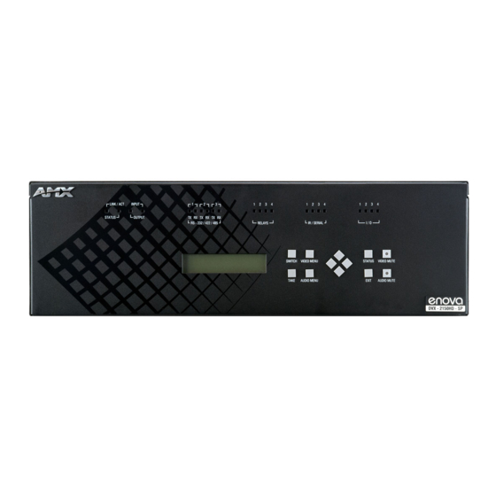
Wiring and Device Connections Wiring and Device Connections Overview This chapter provides functional details for each item on the front and rear panel of the DVX. Wiring specifications are also provided, when applicable. FIG. 3 displays the front panel of the DVX-2150HD-SP and DVX-2155HD-SP: INPUT LED Relay RS232/422/485... - Page 20 Wiring and Device Connections FIG. 4 displays the rear panel of the DVX-2150HD-SP: MULTI FORMAT VIDEO INPUTS S/PDIF Power OUTPUT connector AUDIO AUDIO OUTPUTS HDMI INPUTS INPUT INPUTS LAN port INPUTS OUTPUT I/O (Port 9) Config DIP IR/SERIAL RS232/422/485 ports switch Ports 5-8) RELAYS (port 4)
-
Page 21: Front Panel Controls And Indicators
Wiring and Device Connections Front Panel Controls and Indicators The following sub-sections describe each component on the front panel of the DVX. Refer to FIG. 3 on page 7 for the component layout of the front panel. LEDs The LEDs on the front panel (FIG. 7) indicate the communications status of several different connections, as described in the table below: LINK/ACT LED Status LED... -
Page 22: Switch Pushbutton
Wiring and Device Connections SWITCH Pushbutton Press the SWITCH pushbutton (FIG. 9) to access the SWITCH menu on the LCD display. Press this button to switch the audio, video, or both from any input to any output. Press the TAKE pushbutton to implement the switch. FIG. -
Page 23: Audio Menu Pushbutton
Wiring and Device Connections AUDIO MENU Pushbutton Press the AUDIO MENU pushbutton (FIG. 12) to access the audio options, displayed on the LCD display. There are three audio menus (AUDIO OUTPUT, AUDIO INPUT, and MIC) and all are accessible by using this button. Multiple presses cycle through the various AUDIO menus. -
Page 24: Status Pushbutton
Wiring and Device Connections STATUS Pushbutton Press the STATUS pushbutton (FIG. 14) to access the STATUS menu on the LCD display. FIG. 14 STATUS pushbutton The STATUS menu enables you to see status information such as IP address and installed firmware versions as well as adjust LCD and LED backlight intensity. -
Page 25: Rear Panel Audio Inputs And Outputs
Wiring and Device Connections Rear Panel Audio Inputs and Outputs The following sub-sections describe each component on the rear panel of the DVX. Refer to FIG. 4 on page 8 for the component layout of the rear panel. AUDIO INPUTS (1-2) The two AUDIO INPUTS connectors are female 1/8"... - Page 26 Wiring and Device Connections Source devices require either balanced (differential) or unbalanced (single-ended) connections. FIG. 19 illustrates options for wiring between sources and input connectors. More than one option can be used in the same system. source device Balanced wiring Unbalanced wiring FIG.
-
Page 27: Mic Inputs (1-2)
Wiring and Device Connections MIC INPUTS (1-2) Two 3.5mm 3-pin captive-wire MIC INPUT connectors (FIG. 21) allow up to two mono microphones to be connected to the DVX. Each microphone input supports balanced and unbalanced audio. Each input supports up to 48V of phantom power. -
Page 28: Amp Out
Wiring and Device Connections AMP OUT The AMP OUT amplified audio output (FIG. 23) differs according to the DVX model you are using: The 4-position captive wire connector for -SP models provides amplified, variable, mono or stereo audio output. ... -
Page 29: Audio Outputs
Wiring and Device Connections AUDIO OUTPUTS The Line Level audio outputs provide balanced or unbalanced, mono or stereo line-level audio output. FIG. 26 Audio outputs Destination devices require either balanced (differential) or unbalanced (single-ended) connections. FIG. 27 illustrates options for wiring between output connectors and the destinations. destination device Balanced wiring Unbalanced wiring... -
Page 30: Rear Panel Video Inputs And Outputs
Wiring and Device Connections Rear Panel Video Inputs and Outputs The following sub-sections describe each component on the rear panel of the DVX. All digital inputs and outputs on the DVX support HDCP. Refer to FIG. 4 on page 8 for the component layout of the rear panel. MULTI-FORMAT VIDEO INPUTS (1-2) The two MULTI-FORMAT VIDEO INPUT connectors on the rear panel are used to connect video source input devices to the DVX (FIG. - Page 31 HDMI Male to DVI-D Male Cable section on page 43 The DVX and the adapter cables listed above utilize industry-standard pinouts. The only adapter cable that is unique to AMX is the CC-DVI-SVID (DVI-to-S-Video) cable. The others are generally available to purchase from other vendors, assuming that they also utilize industry standard (or equivalent) pinouts.
-
Page 32: Hdmi Inputs (3-6)
Wiring and Device Connections HDMI INPUTS (3-6) The four HDMI INPUT connectors (ports 3-6) on the rear panel are used to connect source input devices to the DVX-2150HD-SP (FIG. 30). The DVX-2150HD-SP routes digital video and audio from connected source input devices to the connected output devices. -
Page 33: Dxlink Inputs (5-6)
Wiring and Device Connections To connect HDMI input source devices (DVI and HDMI) to the HDMI INPUT connectors, the following (optional) adapter cables are required: DVI Input Adapter Cables Name Description Length HDMI Interface HDMI Male to HDMI Male 6 1/2’ (2m) FG10-2178-05 Cable HDMI to DVI Cable... -
Page 34: Video Outputs (1-3)
Wiring and Device Connections VIDEO OUTPUTS (1-3) The VIDEO OUTPUTS includes 2 different types of connectors: 2 HDMI Output connectors (1-2) each provide scaled digital DVI video and HDMI audio and video output. 1 DXLink Twisted Pair output (3) providing digital video, embedded audio, Ethernet (ICSP commands only), and bi-directional control and power over Category Cable to DXLink Receivers. -
Page 35: Twisted Pair Cable Pinouts
Wiring and Device Connections Twisted Pair Cable Pinouts AMX supports both the T568A and T568B pinout specifications for termination of the twisted pair cable used between the DVX and the DXLink receiver. FIG. 35 Twisted pair cable pinouts for T568A (recommended) and T568B specifications... -
Page 36: Rear Panel Control And Power
Wiring and Device Connections Rear Panel Control and Power The following sub-sections describe each component on the rear panel of the DVX. Refer to FIG. 4 on page 8 for the component layout of the rear panel. RS232/422/485 Serial Port Connectors (PORTS 1-3) The RS232/422/485 serial device ports (FIG. -
Page 37: Relays (Port 4)
Wiring and Device Connections RELAYS (PORT 4) You can connect up to four independent external relay devices to the Relay connectors on the device (FIG. 38). When a relay is "OFF", terminals A and B are open-circuit. When a relay is "ON", terminals A and B are shorted together. FIG. -
Page 38: Ir/Serial (Ports 5-8)
Wiring and Device Connections IR/SERIAL (PORTS 5-8) You can connect up to four IR- or Serial-controllable devices to the IR/SERIAL connectors (FIG. 40). FIG. 40 IR/SERIAL connectors The IR/SERIAL connectors accept an IR Emitter (CC-NIRC) that mounts onto the controlled device's IR window, or a mini-plug (CC-NSER) that connects to the controlled device's control jack. -
Page 39: Config Dip Switch
Wiring and Device Connections CONFIG DIP Switch Use the Configuration DIP switch to set the information used by the PROGRAM Port for communication or to set the on-board Master to Program Run Disable (PRD) mode. Position 1 UP (ON) = PRD mode enabled Position 1 DOWN (OFF) = Normal (default) mode - PRD mode disabled Switch position 1 sets PRD mode (UP = ON) FIG. -
Page 40: Program Port
Wiring and Device Connections Consider equating PRD Mode to a PC’s SAFE Mode setting. With PRD mode, you can continue to power a unit, update the firmware, and download a new program while circumventing any problems with a currently downloaded program. You must power cycle the unit after activating/deactivating PRD mode on Program Port DIP switch #1. -
Page 41: Id Pushbutton
Wiring and Device Connections ID Pushbutton The ID pushbutton (FIG. 43) sets the NetLinx ID assignments of the Internal Control Device. It has no effect on the Internal Switcher Device. Only the 5001 ID can be changed. It is not possible to change the 5002 device ID. FIG. -
Page 42: Axlink Port And Led (4-Pin Captive-Wire)
Wiring and Device Connections AxLink Port and LED (4-pin captive-wire) The AxLink port (FIG. 47) allows the DVX to support AMX AxLink devices. FIG. 47 AxLink Port and LED The (green) AxLink LED indicates AxLink data activity: Off - No power, or the controller is not functioning properly. -
Page 43: Power Connector/Switch/Fuse
Wiring and Device Connections To use the 4-pin 3.5 mm mini-Phoenix (female) captive-wire connector for data communication and power transfer, the incoming PWR and GND cable from the 12 VDC-compliant power supply must be connected to the AxLink cable connector going to the DVX. FIG. 49 shows the wiring diagram. To the Controller’s Local 12+ VDC AxLink/PWR connector... - Page 44 Wiring and Device Connections Enova DVX-2150HD/2155HD All-in-One Presentation Switcher Operation/Reference Guide...
-
Page 45: Cable Details And Pinout Information
Cable Details and Pinout Information Cable Details and Pinout Information Overview The DVI-I Input connectors on the rear panel are used to connect video source input devices to the DVX (FIG. 51). The DVX routes video from connected source input devices to the connected output device. Each connector supports HDMI and DVI as well as VGA, S-Video, Composite, and Component inputs. -
Page 46: Dvi-D Male To Dvi-D Male Single-Link Cable
Cable Details and Pinout Information DVI-D Male to DVI-D Male Single-Link Cable Cable to be composed of the following: Four UL20276 (28AWG twisted pair + drain wire + aluminum foil/mylar shield) for TMDS signals and shields Five UL1589 (28AWG) for DDC_CLK, DDC_DATA, Hot_Plug_Detect, +5VDC, and GROUND ... -
Page 47: Dvi-A Male To 5-Bnc Male Cable
Outer braid DVI-A Male to 5-BNC Male Cable This cable type corresponds to the CC-DVI-5BNCM DVI-to-Component cable (FG10-2170-08), available from AMX. Cable to be composed of the following: Five 75ohm 28 AWG mini-coax cables for the Red, Green, Blue, VSync, and HSync signals and returns ... - Page 48 Cable Details and Pinout Information DVI-to-5-BNC Cable Pinout Information (Cont.) DVI-A Signal Name Signal Name Notes: Connector connector +5VDC Pin populated in DVI-A connector, but not connected for this cable GROUND VSync, HSync Black/Grey Returns (shields) shields HOT PLUG DETECT Pin populated in DVI-A connector, but not connected for this cable TMDS DATA 0 N...
-
Page 49: Dvi-A Male To Triple Rca Male Cable
Cable Details and Pinout Information DVI-A Male to Triple RCA Male Cable This cable type corresponds to the CC-DVI-RCA3M DVI-to-Component/Composite cable (FG10-2170-09), available from AMX. Cable to be composed of the following: Three 75ohm 28 AWG mini-coax cables for the Red, Green, and Blue signals and returns ... - Page 50 Cable Details and Pinout Information DVI-to-Triple RCA Cable Pinout Information (Cont.) DVI-A Signal Name Signal RCA connector Notes: Connector Name TMDS DATA 0 N Pin populated in DVI-A connector, but not connected for this cable TMDS DATA 0 P Pin populated in DVI-A connector, but not connected for this cable TMDS SHIELD 0/5...
-
Page 51: Dvi-A Male To S-Video Male Cable
Cable Details and Pinout Information DVI-A Male to S-Video Male Cable This cable corresponds to the CC-DVI-SVID DVI-to-S-Video adapter cable (FG10-2170-10), available from AMX. Cable to be composed of the following: Two 75ohm 28 AWG mini-coax cables for the Luminance (Y) and Chrominance (C) signals and returns ... - Page 52 Cable Details and Pinout Information DVI-to-S-Video Cable Pinout Information (Cont.) DVI-A Signal Name Signal Name S-Video Notes: Connector Connector TMDS DATA 5 N Pin not populated in DVI-A connector TMDS DATA 5 P Pin not populated in DVI-A connector TMDS CLOCK Pin not populated in DVI-A SHIELD connector...
-
Page 53: Dvi-A Male To Hd15 (Vga) Male Adapter
Cable Details and Pinout Information DVI-A Male to HD15 (VGA) Male Adapter This cable type corresponds to the CC-DVIM-VGAF DVI-to-VGA adapter (FG10-2170-13), available from AMX. Cable to be composed of the following: Three 75ohm 28 AWG mini-coax cables for the Red, Green, and Blue signals and returns ... - Page 54 Cable Details and Pinout Information DVI-to-VGA Cable Pinout Information (Cont.) DVI-A Signal Name Signal Name HD15 Notes: Connector (VGA) Pin C1 ANALOG Red mini-coax signal Coax Signal C2 ANALOG GREEN Green mini-coax signal GREEN Coax Signal C3 ANALOG BLUE Blue mini-coax signal BLUE Coax Signal C4 ANALOG...
-
Page 55: Hdmi Male To Dvi-D Male Cable
Cable Details and Pinout Information HDMI Male to DVI-D Male Cable HDMI-to-DVI-D Cable Pinout Information HDMI-to-DVI-D Cable Pinout Information HDMI Signal Name Wire DVI-D Pin Notes: Connector TMDS Data 2+ TMDS Data Shield B TMDS Data 2- TMDS Data 1+ TMDS Data Shield B TMDS Data 1- TMDS Data 0+... - Page 56 Cable Details and Pinout Information Enova DVX-2150HD/2155HD All-in-One Presentation Switcher Operation/Reference Guide...
-
Page 57: Audio/Video Configuration
Audio/Video Configuration Audio/Video Configuration You can access the configuration settings for the DVX by using one of the following methods: Using the front panel buttons Using a Web browser Using the Front Panel Buttons You can access the configuration settings for the DVX by using the VIDEO MENU, AUDIO MENU, SWITCH, and STATUS buttons on the front panel of the DVX. -
Page 58: Video Settings
Audio/Video Configuration Video Settings The following table lists the Video Output menu options available by pressing the VIDEO MENU button. Video Output Menu Options Output Select Use the left and right navigational buttons to manually select which video output you want to use. - Page 59 Audio/Video Configuration Video Output Menu Options (Cont.) V Size Use the left and right navigational buttons to set the vertical size of the image for the selected output. You can set the size from 25 to 800. The default setting is 100. V Shift Use the left and right navigational buttons to move the location of the video output up and down.
-
Page 60: Setting The Video Type For A Video Input
Audio/Video Configuration Video Input Menu Options (Cont.) Saturation Use the left and right navigational buttons to alter the saturation level adjustment applied to the selected input. You can set the saturation level from 0-100. The default setting is Use the left and right navigational buttons to alter the hue adjustment applied to the selected input. -
Page 61: Selecting A Video Test Pattern
Audio/Video Configuration Selecting a Video Test Pattern Selecting a test pattern for your input source can help determine if the displays are connected correctly. Perform these steps the select a test pattern: Press the VIDEO MENU button on the front panel of the DVX to open the Video Output menu. Press the left and right navigation buttons to select the output on which to display the test pattern (ALL, 1, or 2). - Page 62 Audio/Video Configuration Audio Output Menu Options (Cont.) Test Tone Use the left and right navigational buttons to select an internally generated audible tone. The selected tone overrides any input source selection. Selecting 'Off' removes the override, allowing you to hear audio from the selected source.You can choose from Off, 60Hz, 250Hz, 400Hz, 1kHz, 3kHz, 5kHz, 10kHz, Pink Noise, and White Noise.
-
Page 63: Microphone Settings
Audio/Video Configuration Microphone Settings The following table lists the microphone options available on the LCD display by pressing the AUDIO MENU button on the front panel: Mic Input Menu Options Mic Input Mode Use the left and right navigational buttons to manually select Single Stereo to adjust both microphone inputs or Dual Mono Mode to adjust the microphone settings individually. -
Page 64: Switch Menu
Audio/Video Configuration Switch Menu Press the SWITCH button to access the Switch menu for switching between the available audio and video devices. Use the UP and DOWN navigational buttons to scroll through the menu options. Use the RIGHT and LEFT navigational buttons to selected the desired input and output. -
Page 65: Dvx Webconsole
Audio/Video Configuration DVX WebConsole The DVX features an on-board WebConsole that allows you to configure the device and make various adjustments to audio/video and system settings. The WebConsole is accessed via a web browser on a PC that has network access to the DVX. -
Page 66: Master Controller Configuration Options
NetLinx System. Master Configuration Manager - Additional Documentation NI & DVX Central Controllers WebConsole & For a full description of all Master Configuration pages, refer to the Programming Guide, available at www.amx.com. Enova DVX-2150HD/2155HD All-in-One Presentation Switcher Operation/Reference Guide... -
Page 67: Using A Web Browser
Using a Web Browser You can access the configuration settings for the DVX by using a web browser. (AMX supports any industry-standard web browser running Adobe Flash Player 10 or better.) The system configuration pages are available by entering the IP address of the NetLinx master into the location bar of your web browser. -
Page 68: Locating The Ip Address Of The Dvx
Audio/Video Configuration Locating the IP Address of the DVX You can locate the IP address of the DVX by using the buttons on the front panel of the DVX. The IP address appears on the LCD display on the front panel of the DVX. Perform these steps to locate the IP address of the unit: Press the STATUS button on the front panel of the unit. -
Page 69: Video Settings
Audio/Video Configuration The following table lists the general options for the WebConsole Configuration page: General Options Mute Turns off the audio for the device. Amp Volume Sets the output volume. Refresh Click to reload all settings. Reset to Defaults Click to reset the current page’s settings to its factory default. Video tab Click this tab to access the video settings for the device. -
Page 70: Selecting A Logo File
Video Out tab. Images must be 24-bit color bitmap files at least 36x36 pixels in size. Large images can cause a slowdown in performance. Though images up to 1920x1200 are supported, AMX recommends using an image size no greater than 640x480. -
Page 71: Video In
Audio/Video Configuration Using concurrent web browsers or users while uploading or saving logo files can cause corruption in your logos. It is a best practice to use only a single web browser when uploading or saving a logo file. Closing and restarting your web browser removes all current logo file information from the Web Console page. - Page 72 Audio/Video Configuration 4 - Select Output: Use the menu to select the video output you want to use. 5 - Resolution: Click Auto to have the unit automatically detect the video resolution for the selected input signal Select a video resolution from the drop-down menu manually, which auto-selects Manual mode. Select Bypass if the DVX should not process the output device's resolution.
-
Page 73: Audio Settings
Audio/Video Configuration Audio Settings The Audio page enables you to set the audio qualities for each audio input, microphone input, amplifier output, and line output. Any changes you make reflect instantaneously on your source input and output devices. Audio Out FIG. - Page 74 Audio/Video Configuration 5 - Select Input: Use the menu to switch the audio input to the selected audio output. 6 - Output Format: Use the menu to change the audio format of the selected audio output. You can set the audio format to Stereo or Mono.
-
Page 75: Audio In/Microphone
Audio/Video Configuration Audio In/Microphone FIG. 61 displays the Audio In/Microphone page for the DVX. FIG. 61 WebConsole Configuration page - Audio In/Microphone tab 1 - Audio Input: Select the corresponding option button to switch that audio signal to the selected output. You can only select one audio input at a time. - Page 76 Audio/Video Configuration 8 - Microphone Adjustment: There are two separate sections for configuring Mic 1 and Mic 2. If you select Single Stereo for the Microphone Mode, there is a single configuration that affects both microphones. Selecting Dual Mono allows independent configuration of each mic. You can set the following options for each microphone: PreAmp Gain: Use the slider to set the preamp gain level for the mic.
-
Page 77: Setting Up Surround Audio
Audio/Video Configuration Setting Up Surround Audio To pass surround audio from HDMI inputs to HDMI or S/PDIF outputs you must have an HDMI sink (display, AVR, etc.) that supports one or more surround formats. Follow these steps to configure the DVX to pass-through surround audio. -
Page 78: Mixing Microphones Onto Analog And Hdmi Outputs
Audio/Video Configuration Mixing Microphones onto Analog and HDMI Outputs Follow these steps to connect and mix audio from a microphone input onto the source audio being routed to an audio output. The Mic inputs can accept both Microphone level and Line level audio. Connect an audio source to one of the microphone inputs on the DVX. -
Page 79: System Settings
Note: Due to the way many browsers manage file upload requests while in an authenticated session, it is not possible to load a DVX setup (.xdv) file with any web browser AMX has tested, except Microsoft Internet Explorer when HTTP Security is enabled on the DVX Master. - Page 80 Audio/Video Configuration 7 - System Information: This area provides the following read-only information about your unit: • Serial number • IP Gateway • Temperature (ºC) • MAC Address • IP DNS Addresses • Temperature Alarm • IP Hostname • Switcher Firmware Version •...
-
Page 81: Netlinx Firmware Upgrades
Upgrading firmware on Enova DVX All-In-One Presentation Switchers involves downloading the latest firmware files from www.amx.com and using NetLinx Studio to transfer the files to a target DVX. The NetLinx Studio software application (available for free download from www.amx.com) provides the ability to transfer KIT firmware files to a NetLinx device such as the DVX. -
Page 82: Before You Start
Verify you have the latest version of NetLinx Studio on your PC. Use the Web Update option in NetLinx Studio’s Help menu to obtain the latest version. Alternatively, go to www.amx.com and login as a Dealer to download the latest version. -
Page 83: Downloading The Latest Firmware Files From Www.amx.com
Downloading Enova DVX Firmware Files on www.amx.com Visit the appropriate product page on www.amx.com for the latest NI Master, Device Controller, and A/V Switcher/ Scaler firmware (*.kit) files for your DVX. Firmware file links are available along the right-side of the catalog page (FIG. -
Page 84: Sending Firmware (*.Kit) Files To The Dvx
DVX use KIT files for firmware upgrades. A Kit file (*.KIT) is a package of several files, all of which are required to upgrade the firmware, and are available online via www.amx.com. Firmware download links are provided in the relevant product page. - Page 85 NetLinx Firmware Upgrades Click the Browse (...) button to navigate to the target directory in the Browse For Folder dialog (FIG. 66). FIG. 66 Browse For Folder dialog (NetLinx Studio) The selected directory path is displayed in the Send To NetLinx Device dialog (Location text box). ...
-
Page 86: Additional Documentation
Failure to complete this operation successfully may require a factory repair of the DVX. Additional Documentation For additional information on using NetLinx Studio, refer to the NetLinx Studio online help and Operation/Reference Guide (available at www.amx.com). Enova DVX-2150HD/2155HD All-in-One Presentation Switcher Operation/Reference Guide... -
Page 87: Programming
Programming Programming The chapter defines all programming commands available for the DVX. This chapter lists programming commands unique to the DVX. Please consult the WebConsole & Programming Guide for NetLinx Integrated Controllers for more details on NetLinx controller commands. The DVX supports all commands compatible with the NI-3101-SIG. -
Page 88: Netlinx Channels And Levels
Programming NetLinx Channels and Levels The following sections define the NetLinx channels and levels available for the DVX: NetLinx Channels NetLinx Channels Channel Ports Description Volume Up Volume Down Volume Mute Cycle Switches video input 1 to the video output specified in the DPS Switches video input 2 to the video output specified in the DPS Switches video input 3 to the video output specified in the DPS Switches video input 4 to the video output specified in the DPS... -
Page 89: Standby Mode
Programming NetLinx Channels (Cont.) Channel Ports Description Video In Contrast Ramp Up (only applicable when routed to a scaled output) Video In Contrast Ramp Down (only applicable when routed to a scaled output) Video In Hue Ramp Up (only applicable when routed to a scaled output) Video In Hue Ramp Down (only applicable when routed to a scaled output) -
Page 90: Netlinx Levels
Programming NetLinx Levels NetLinx Levels Level Ports Range Function 0-100 Output volume (-20)-(20) Audio Output Balance (-24)-(24) Audio Input Gain Temperature (read-only level) 0-100 Input Video Brightness (only applicable when routed to a scaled output) 0-100 Input Video Saturation (only applicable when routed to a scaled output) 0-100 Input Video Contrast (only applicable when routed to a scaled output) -
Page 91: Send_Commands
Programming SEND_COMMANDS The commands listed in the following sections are for the switcher only. For generic NetLinx commands, see the NetLinx Integrated Controllers WebConsole and Programming Guide. The commands derive their input/output port addressing from the target D:P:S. INPUT ports range from 5-14 for Audio and from 1-10 for Video. -
Page 92: Audio Send_Commands
Programming AUDIO SEND_COMMANDs The following table lists the audio SEND_COMMANDs available for the DVX: Audio SEND_COMMANDs AI<input>O<output> Switches audio input port <input> to audio output port <output>. Syntax: Switches audio input port to audio output port SEND_COMMAND "'AI<input>O<output>'" Variables: input = The source audio input number. output = The audio output port number to switch to. -
Page 93: Audin_Compression_Ratio
Programming Audio SEND_COMMANDs (Cont.) AUDIN_COMPRESSION Sets the ratio while compressing for the audio input port addressed by the _RATIO D:P:S. Syntax: Sets the compression ratio for the audio port. SEND_COMMAND <DEV>, "'AUDIN_COMPRESSION_RATIO-<ratio>'" Variable: ratio = 1 to 20 Example: SEND_COMMAND AUDIO_INPUT_1, "'AUDIN_COMPRESSION_RATIO-5'" ?AUDIN_COMPRESSION Requests the compression's release. -
Page 94: Audin_Digital
Programming Audio SEND_COMMANDs (Cont.) AUDIN_DIGITAL Sets the supported audio format in the EDID for the video input addressed by the D:P:S. Sets the digital format for the Syntax: audio port. SEND_COMMAND <DEV>, "'AUDIN_DIGITAL-<format>'" Variable: format = LPCM, AC3, DTS, MPEG, AAC Example: SEND_COMMAND AUDIO_INPUT_1, "'AUDIN_DIGITAL-AAC'"... -
Page 95: Audio_Mute
Programming Audio SEND_COMMANDs (Cont.) AUDIO_MUTE See the AUDOUT_MUTE command on page 97. ?AUDMIC_ Requests the setting of compression for a microphone. COMPRESSION Syntax: Requests the compression SEND_COMMAND <DEV>, "'?AUDMIC_COMPRESSION'" setting for the microphone. Example: SEND_COMMAND MICROPHONE_1, "'?AUDMIC_COMPRESSION'" Returns a COMMAND string of the form: AUDMIC_COMPRESSION-<setting>. AUDMIC_COMPRESSION Sets the setting of compression of the microphone port addressed by the D:P:S to <setting>. -
Page 96: Audmic_Compression_Release
Programming Audio SEND_COMMANDs (Cont.) ?AUDMIC_ Requests the duration of the release phase while compressing for a COMPRESSION_ microphone. RELEASE Syntax: Requests the release phase SEND_COMMAND <DEV>, "'?AUDMIC_COMPRESSION_RELEASE'" while compressing setting Example: for the microphone. SEND_COMMAND MIC_1, "'?AUDMIC_COMPRESSION_RELEASE'" Returns a COMMAND string of the form: AUDMIC_COMPRESSION- RELEASE-<release>. -
Page 97: Audmic_Duck_Hold
Programming Audio SEND_COMMANDs (Cont.) AUDMIC_DUCK_HOLD Sets the duration of the hold phase while ducking for the microphone port addressed by the D:P:S. Sets the ducking hold for the Syntax: microphone port. SEND_COMMAND <DEV>, "'AUDMIC_DUCK_HOLD-<hold>'" Variable: hold = 0 to 2000 Example: SEND_COMMAND MICROPHONE_1, "'AUDMIC_DUCK_HOLD-200'"... -
Page 98: Audmic_Eq_Ft
Programming Audio SEND_COMMANDs (Cont.) ?AUDMIC_EQ_FT Requests the filter type of the specified microphone band of the equalizer for the microphone port addressed by the D:P:S. Requests the filter type of Syntax: the specified microphone band of the equalizer for the SEND_COMMAND <DEV>, "'?AUDMIC_EQ_FT-<band>'"... -
Page 99: Audmic_Eq_Q
Programming Audio SEND_COMMANDs (Cont.) AUDMIC_EQ_Q Sets the quality factor (Q) for the specified microphone band of the equalizer for the microphone port addressed by the D:P:S. Sets the quality factor (Q) for Syntax: the specified microphone band of the equalizer for the SEND_COMMAND <DEV>, "'AUDMIC_EQ_Q-<band>,<factor>'"... -
Page 100: Audmic_Gating_Hold
Programming Audio SEND_COMMANDs (Cont.) ?AUDMIC_GATING Requests the duration of the attack phase while gating from the microphone _ATTACK port addressed by the D:P:S. Syntax: Requests the attack phase while gating for the SEND_COMMAND <DEV>, "'?AUDMIC_GATING_ATTACK'" microphone port. Example: SEND_COMMAND MIC_1, "'?AUDMIC_GATING_ATTACK'" Returns a string of the form: ?AUDMIC_GATING_ATTACK=<value>. -
Page 101: Audmic_Gating_Release
Programming Audio SEND_COMMANDs (Cont.) ?AUDMIC_GATING Requests the duration of the release phase while gating from the microphone _RELEASE port addressed by the D:P:S. Syntax: Requests the release phase while gating for the SEND_COMMAND <DEV>, "'?AUDMIC_GATING_RELEASE'" microphone port. Example: SEND_COMMAND MIC_1, "'?AUDMIC_GATING_RELEASE'" Returns a string of the form: ?AUDMIC_GATING_RELEASE=<value>. -
Page 102: Audmic_Limiter_Attack
Programming Audio SEND_COMMANDs (Cont.) ?AUDMIC_LIMITER Requests the duration of the attack phase while limiting from the microphone _ATTACK port addressed by the D:P:S. Syntax: Requests the attack phase while limiting for the SEND_COMMAND <DEV>, "'?AUDMIC_LIMITER_ATTACK'" microphone port. Example: SEND_COMMAND MIC_1, "'?AUDMIC_LIMITER_ATTACK'" Returns a string of the form: ?AUDMIC_LIMITER_ ATTACK=<... -
Page 103: Audmic_On
Programming Audio SEND_COMMANDs (Cont.) ?AUDMIC_ON Requests the status of the microphone port addressed by the D:P:S. Syntax: Requests the status of the microphone port. SEND_COMMAND <DEV>, "'?AUDMIC_ON'" Example: SEND_COMMAND MICROPHONE_1, "'?AUDMIC_ON'" Returns a COMMAND string of the form: AUDMIC_ON-<setting>. AUDMIC_ON Enables or disables the microphone port addressed by the D:P:S. -
Page 104: Audmic_Stereo
Programming Audio SEND_COMMANDs (Cont.) AUDMIC_STEREO Sets which microphone port addressed by the D:P:S to use. Syntax: Sets the microphone to be used by the microphone SEND_COMMAND <DEV>, "'AUDMIC_STEREO-<option>'" port. Variable: option = "dual mono" or "single stereo" Example: SEND_COMMAND MIC_1, "'AUDMIC_STEREO-single stereo'" Sets the microphone port (#1 based on the D:P:S) to use both the microphone inputs as dual mono. -
Page 105: Audout_Duck_Attack
Programming Audio SEND_COMMANDs (Cont.) AUDOUT_DUCK_ATTACK Sets the duration of the attack phase while ducking for the output port addressed by the D:P:S. Sets the ducking attack for Syntax: the output port. SEND_COMMAND <DEV>, "'AUDOUT_DUCK_ATTACK-<attack>'" Variable: attack = 1 to 2000 Example: SEND_COMMAND AUDIO_OUTPUT_1, "'AUDOUT_DUCK_ATTACK-200'"... -
Page 106: Audout_Duck_Priority
Programming Audio SEND_COMMANDs (Cont.) AUDOUT_DUCK Sets which microphone for the audio port addressed by the D:P:S to prioritize. _PRIORITY Syntax: Sets the ducking priority for SEND_COMMAND <DEV>, "'AUDOUT_DUCK_PRIORITY-<option>'" the output port. Variable: option = mic1 or none Example: SEND_COMMAND AUDIO_OUTPUT_1, "'AUDOUT_DUCK_PRIORITY-mic1'" Gives priority to microphone 1 over microphone 2. -
Page 107: Audout_Ducking
Programming Audio SEND_COMMANDs (Cont.) AUDOUT_DUCKING Sets the setting of ducking for the audio port addressed by the D:P:S. Syntax: Sets the ducking for the audio port. SEND_COMMAND <DEV>, "'AUDOUT_DUCKING-<setting>'" Variable: setting = off, low, medium, high, custom Example: SEND_COMMAND AUDIO_OUTPUT_1, "'AUDOUT_DUCKING-low'" Sets the ducking for the audio output port (#1 based on D:P:S) to low. -
Page 108: Audout_Eq_Gain
Programming Audio SEND_COMMANDs (Cont.) AUDOUT_EQ_GAIN Sets the gain on the equalizer band <band> on the output audio port addressed by the D:P:S to <value>. Sets the gain on the Syntax: specified equalizer band on the audio output port. SEND_COMMAND <DEV>, "'AUDOUT_EQ_GAIN-<band>,<value>'" Variables: band = 1..10 if on the audio output port. -
Page 109: Audout_Maxvol
Programming Audio SEND_COMMANDs (Cont.) ?AUDOUT_MAXVOL Requests the current maximum volume for the audio port addressed by the D:P:S. Requests the maximum Syntax: volume for the audio port. SEND_COMMAND <DEV>, "'?AUDOUT_MAXVOL'" Example: SEND_COMMAND AUDIO_OUTPUT_1, "'?AUDOUT_MAXVOL'" Returns a COMMAND string of the form: AUDOUT_MAXVOL-<maximum>. AUDOUT_MAXVOL Sets the maximum volume for the audio port addressed by the D:P:S. -
Page 110: Audout_Stereo
Programming Audio SEND_COMMANDs (Cont.) AUDOUT_STEREO Syntax: SEND_COMMAND <device>, "'AUDOUT_STEREO-<setting>'" Enables or disables audio amp output in stereo Variables: setting = Stereo setting, either "ENABLE" or "DISABLE" Example: SEND_COMMAND dxDev,"'AUDOUT_STEREO-ENABLE'" ?AUDOUT_TESTTONE Requests the current frequency of test tone for the audio port addressed by the D:P:S. -
Page 111: Hdmiout_Audio
Programming Audio SEND_COMMANDs (Cont.) ?HDMIOUT_AUDIO Requests which HDMI output port is currently followed by the audio port addressed by the D:P:S. Requests the HDMI output Syntax: port followed by the audio port. SEND_COMMAND <DEV>, "'?HDMIOUT_AUDIO'" Example: SEND_COMMAND AUDIO_OUTPUT_1, "'?HDMIOUT_AUDIO'" Returns a COMMAND string of the form: HDMIOUT_AUDIO-<option>. HDMIOUT_AUDIO Determines which output the HDMI output port addressed by the D:P:S will use. -
Page 112: Spdifout_Audio
Programming Audio SEND_COMMANDs (Cont.) SPDIFOUT_AUDIO Selects which output the audio port should connect to. Syntax: Sets the output the audio port is connected to. SEND_COMMAND <DEV>, "'SPDIFOUT_AUDIO-<option>'" Variable: option = off, HDMI out 1, HDMI out 2, HDMI out 3, HDMI out 4, analog out 1, analog out 2, analog out 3, analog out 4 Example: SEND_COMMAND AUDIO_OUTPUT_1, "'SPDIFOUT_AUDIO-HDMI analog out... -
Page 113: Video Send_Commands
Programming Video SEND_COMMANDs The following table lists the video SEND_COMMANDs available for the DVX: Video SEND_COMMANDs CI<input>O<output> Switches both the audio and video input to the output port. Syntax: Switches both the audio and video input port to the output SEND_COMMAND <DEV>, "'CI<input>O<output>'"... -
Page 114: Output
Programming Video SEND_COMMANDs (Cont.) ?OUTPUT If the input port is not connected to any output port then the reply will indicate this with an output port number of ZERO (0). Requests for the outputs Syntax: connected to an input. SEND_COMMAND <DEV>, "'?OUTPUT-<sl>,<input>'" Variables: sl = AUDIO, VIDEO, or ALL. -
Page 115: Vidin_Bw
Programming Video SEND_COMMANDs (Cont.) VIDIN_BW Enables or disables the COLOR setting on the video port addressed by the D:P:S. If enabled, then the COLOR setting is true. If disabled, then the COLOR Enables the color setting for setting is false which means it's Black & White instead. the video input port. -
Page 116: Vidin_Format
Programming Video SEND_COMMANDs (Cont.) ?VIDIN_FORMAT Requests the input format of the video port addressed by the D:P:S. Syntax: Requests the input format of the video port. SEND_COMMAND <DEV>, "'?VIDIN_FORMAT'" Example: SEND_COMMAND VIDEO_INPUT_1,"'?VIDIN_FORMAT'" Returns a COMMAND string of the form: VIDIN_FORMAT-<format>. VIDIN_FORMAT Sets the input format of the video port addressed by the D:P:S to <format>. -
Page 117: Vidin_Hshift
Programming Video SEND_COMMANDs (Cont.) VIDIN_HSHIFT Sets the horizontal shift of the video port addressed by the D:P:S to <value>. Syntax: Sets the horizontal shifting of the VGA video input port. SEND_COMMAND <DEV>, "'VIDIN_HSHIFT-<value>'" Variables: value = -50..50 Example: SEND_COMMAND "'VIDIN_HSHIFT-2'" Sets the Horizontal shifting of VGA video input port (#1 based on D:P:S) to 2 (shift to right). -
Page 118: Vidin_Phase
Programming Video SEND_COMMANDs (Cont.) ?VIDIN_PHASE Requests the input phase of the video port addressed by the D:P:S. This command is valid only for inputs whose format is set to VGA. Requests the input phase Syntax: value of the video port. SEND_COMMAND <DEV>, "'?VIDIN_PHASE'"... -
Page 119: Vidin_Res_Ref
Programming Video SEND_COMMANDs (Cont.) VIDIN_RES_REF Sets the resolution and refresh rate of the video input port addressed by D:P:S. Invalid combinations are ignored by the SWITCHER. Sets the resolution and Syntax: refresh rate of the video input port. SEND_COMMAND <DEV>,"'VIDIN_RES_REF- <horizontal>x<vertical>,<refresh-rate>'"... -
Page 120: Vidin_Vshift
Programming Video SEND_COMMANDs (Cont.) VIDIN_VSHIFT Sets the vertical shift of the video port addressed by the D:P:S to <value>. Syntax: Sets the vertical shifting of the VGA video input port. SEND_COMMAND <DEV>, "'VIDIN_VSHIFT-<value>'" Variables: value = -10..10 Example: SEND_COMMAND "'VIDIN_VSHIFT-2'" Sets the vertical shifting of VGA video input port (#1 based on D:P:S) to 2 (shift upward). -
Page 121: Vidout_Brightness
Programming Video SEND_COMMANDs (Cont.) VIDOUT_BRIGHTNESS Sets the output brightness of the video port addressed by the D:P:S to <value>. Syntax: Sets the output brightness of the video port. SEND_COMMAND <DEV>, "'VIDOUT_BRIGHTNESS-<value>'" Variables: value = 0..100 Example: SEND_COMMAND VIDEO_OUTPUT_1,"'VIDOUT_BRIGHTNESS-50'" Sets the brightness of video output port (#1 based on D:P:S) to 50. ?VIDOUT_CONTRAST Requests the output contrast of the video port addressed by the D:P:S. -
Page 122: Vidout_Hshift
Programming Video SEND_COMMANDs (Cont.) VIDOUT_HSHIFT Sets the horizontal shift of the video output port addressed by the D:P:S to <value>. Sets the horizontal shift of Syntax: the video output port. SEND_COMMAND <DEV>, "'VIDOUT_HSHIFT-<value>'" Variables: value = -127..127 Example: SEND_COMMAND "'VIDOUT_HSHIFT-2'" Sets the horizontal shifting of video output port (#1 based on D:P:S) to 2 (shift to right). -
Page 123: Vidout_Osd
Programming Video SEND_COMMANDs (Cont.) ?VIDOUT_OSD Requests whether the video port addressed by the D:P:S has the OSD setting enabled or disabled. Requests whether the OSD Syntax: setting is enabled. SEND_COMMAND <DEV>, "'?VIDOUT_OSD'" Example: SEND_COMMAND VIDEO_OUTPUT_1,"'? VIDOUT_OSD'" Returns a COMMAND string of the form: VIDOUT_OSD-<ENABLE|DISABLE> VIDOUT_OSD Enables or Disables the On Screen Display (OSD) setting on the video port addressed by the D:P:S. -
Page 124: Vidout_Res_Ref
Programming Video SEND_COMMANDs (Cont.) ?VIDOUT_RES Requests to resolution of the video output port addressed by the D:P:S. Syntax: Requests the resolution of the video output port. SEND_COMMAND <DEV>, "’?VIDOUT_RES’" Example: SEND_COMMAND VIDEO_OUTPUT_1,"’?VIDOUT_RES’" Returns a COMMAND string of the form: VIDOUT_RES-<h>x<v>,<rate>. ?VIDOUT_RES_AUTO See the ?VIDOUT_SCALE command on page 112. -
Page 125: Vidout_Testpat
Programming Video SEND_COMMANDs (Cont.) VIDOUT_TESTPAT Sets the test pattern to display. Syntax: Sets the test pattern for the video output port. SEND_COMMAND <DEV>, "'VIDEO_TESTPAT-<pattern>'" Variables: pattern = Off, Color Bar, Gray Ramp, SMPTE Bar, HiLoTrak, Pluge, X-Hatch, Logo 1, Logo 2, Logo 3 (These options are *not* case sensitive.) Example: SEND_COMMAND VIDEO_OUTPUT_1,"'VIDEO_TESTPAT-X-Hatch'"... -
Page 126: Front Panel Send_Commands
Programming Video SEND_COMMANDs (Cont.) ?VIDOUT_ZOOM Requests the zoom of the video port addressed by the D:P:S. Syntax: Requests the zoom setting value for the video output SEND_COMMAND <DEV>, "'?VIDOUT_ZOOM'" port. Example: SEND_COMMAND VIDEO_OUTPUT_1,"'?VIDOUT_ZOOM'" Returns a COMMAND string of the form: VIDOUT_ZOOM-<value>. VIDOUT_ZOOM Sets the zoom of the image on the video port addressed by the D:P:S to <value>. -
Page 127: Intensity_Lcd
Programming Front Panel SEND_COMMANDs (Cont.) ?INTENSITY_LCD Requests the intensity setting of the LCD screen on the Front Panel. Syntax: Query LCD display light intensity SEND_COMMAND <DEV>, "'?INTENSITY_LCD'" Example: SEND_COMMAND SWITCHER,"'?INTENSITY_LCD'" Returns a COMMAND string of the form: INTENSITY_LCD-<value>. INTENSITY_LCD Sets the intensity of the lighting/brightness of the LCD screen that is part of the Front Panel. -
Page 128: System Send_Commands
Programming System SEND_COMMANDs The following table lists the System SEND_COMMANDs available for the DVX: System SEND_COMMANDs ?DXLINK_ETH Syntax: SEND_COMMAND <DEV>, "'?DXLINK_ETH'" Requests the control setting for the DXLINK output card. Example: SEND_COMMAND SWITCHER,"'?DXLINK_ETH'" Returns a COMMAND string of the form: DXLINK_ETH-<auto|off>. DXLINK_ETH This command instructs the output DXLINK card to disable Ethernet traffic or go to auto mode. -
Page 129: Appendix A - Input Resolutions
Appendix A - Input Resolutions Appendix A - Input Resolutions Available Pixel Display and Refresh Rates The available pixel display and refresh rates for the input devices on the DVX are listed in the following sections. DVI, HDMI, and VGA Supported Input Resolutions DVI, HDMI, and VGA Supported Input Resolutions Resolution Horizontal... - Page 130 Appendix A - Input Resolutions DVI, HDMI, and VGA Supported Input Resolutions (Cont.) Resolution Horizontal Vertical Refresh HDMI & Comments Video Name Active Active (Hz) Support Standard Pixels Lines Support 1280x768@74 1280 VESA DMT 1280x768@75 1280 VESA DMT ...
-
Page 131: Composite And S-Video Supported Input Resolutions
Appendix A - Input Resolutions Composite and S-Video Supported Input Resolutions Composite and S-Video Supported Input Resolutions Resolution Horizontal Vertical Refresh Comments Video Name Active Active (Hz) Standard Pixels Pixels 720x480i@60 480i 720x576i@50 576i Component Video Supported Input Resolutions Component Video Supported Input Resolutions Resolution Horizontal Vertical... - Page 132 Appendix A - Input Resolutions Enova DVX-2150HD/2155HD All-in-One Presentation Switcher Operation/Reference Guide...
-
Page 133: Appendix B - Output Resolutions
Appendix B - Output Resolutions Appendix B - Output Resolutions Available Pixel Display and Refresh Rates The available pixel display and refresh rates for the output devices on the DVX are listed in the following section. DVI and HDMI Supported Output Resolutions DVI and HDMI Supported Output Resolutions Resolution Horizontal... - Page 134 Appendix B - Output Resolutions Enter the Document Name Here...
-
Page 135: Appendix C - Volume Attenuation Table
Appendix C - Volume Attenuation Table Appendix C - Volume Attenuation Table Overview Volume attenuation on the DVX-2150 and 2155 is not set by percentage like it was on earlier DVX models: On the DVX-2150 and 2155 models, the output volume slider changes .5dB per click, to provide a more subtle adjustment. Unity gain is at 88, so a setting of 100 is actually 6dB gain. - Page 136 Appendix C - Volume Attenuation Table Volume Attenuation (Cont.) Percent Decibels Percent Decibels -11.5 -37.0 -12.0 -37.5 -12.5 -38.0 -13.0 -38.5 -13.5 -39.0 -14.0 -41.0 -14.5 -46.0 -15.0 -51.0 -15.5 -56.0 -16.0 -61.0 -16.5 -66.0 -17.0 -71.0 -17.5 -76.0 -18.0 -81.0 -18.5 Infinity...
- Page 137 Appendix C - Video Attenuation Table Enova DVX-2150HD/2155HD All-in-One Presentation Switcher Operation/Reference Guide...
- Page 138 - Schedules and registration for any AMX University course - Travel and hotel information - Your individual certification requirements and progress 3000 RESEARCH DRIVE, RICHARDSON, TX 75082 USA • 800.222.0193 • 469.624.8000 • 469-624-7153 fax • 800.932.6993 technical support • www.amx.com...
Need help?
Do you have a question about the Enova DVX-2150HD-SP and is the answer not in the manual?
Questions and answers