AMX Enova DVX-3150HD-SP Instruction Manual
All-in-one presentation switchers
Hide thumbs
Also See for Enova DVX-3150HD-SP:
- Operation/reference manual (133 pages) ,
- Instruction manual (140 pages)
Table of Contents
Advertisement
IN STR U CT IO N MAN U AL
E N OVA DVX - 3 1 5 X H D / 2 1 X X H D
A L L - I N - O N E P RES E N T AT I O N S W I TC H E RS
DVX-3150HD-SP, DVX-31 50HD-T, DVX-3155HD-SP, DVX-3155HD-T, DVX-3156HD-SP, DVX- 3156HD-T,
DVX-2150HD-SP, DVX-21 50HD-T, DVX-2155HD-SP, DVX-2155HD-T, DVX- 2110HD-SP, DVX -211 0HD-T
Advertisement
Table of Contents

Related Manuals for AMX Enova DVX-3150HD-SP


Summary of Contents for AMX Enova DVX-3150HD-SP
- Page 1 IN STR U CT IO N MAN U AL E N OVA DVX - 3 1 5 X H D / 2 1 X X H D A L L - I N - O N E P RES E N T AT I O N S W I TC H E RS DVX-3150HD-SP, DVX-31 50HD-T, DVX-3155HD-SP, DVX-3155HD-T, DVX-3156HD-SP, DVX- 3156HD-T, DVX-2150HD-SP, DVX-21 50HD-T, DVX-2155HD-SP, DVX-2155HD-T, DVX- 2110HD-SP, DVX -211 0HD-T...
-
Page 2: Important Safety Instructions
COPYRIGHT NOTICE AMX© 2015, all rights reserved. No part of this publication may be reproduced, stored in a retrieval system, or transmitted, in any form or by any means, electronic, mechanical, photocopying, recording, or otherwise, without the prior written permission of AMX. Copyright protection claimed... -
Page 3: Esd Warning
Anyone performing field maintenance on AMX equipment should use an appropriate ESD field service kit complete with at least a dissipative work mat with a ground cord and a UL listed adjustable wrist strap with another ground cord WARNING: Do Not Open! Risk of Electrical Shock. - Page 4 This device is designed and evaluated under the condition of altitude below 2000 meters above sea level; it can only be used in locations below 2000 meters above sea level. Using the device above 2000 meters could result in a potential safety hazard. Enova DVX-315xHD &...
-
Page 5: Table Of Contents
Table of Contents Table of Contents Overview ......................12 Common Application ...................... 12 Audio Processing......................12 Integrated Control ......................13 Enova 315x All-in-One Presentation Switchers ..........14 DVX-3150HD/3155HD/3156HD ..................14 Specifications ......................... 14 Enova 21xx All-in-One Presentation Switchers ..........17 DVX-2150HD/2155HD/2110HD ..................17 Specifications ......................... - Page 6 Table of Contents DXLink INPUTS............................35 VIDEO OUTPUTS............................ 35 315x Video Outputs ............................35 21xx Video Outputs............................. 36 Twisted Pair Cable Pinouts ........................37 Important Twisted Pair Cabling Requirements and Recommendations..........37 Rear Panel Control and Power ..................38 RS232/422/485 Serial Port Connectors ....................38 RELAYS..............................
- Page 7 Overview .......................... 69 Before You Start ......................69 Verifying the Current Firmware Version ................. 69 Downloading the Latest Firmware Files from www.amx.com ........70 Downloading Enova DVX Firmware Files on www.amx.com..............70 Required Order of Firmware Updates for DVX Controllers ..............70 Sending Firmware (*.KIT) Files to the DVX ..............
- Page 8 Table of Contents SEND_COMMANDS ......................79 AUDIO SEND_COMMANDs....................80 AI<input>O<output>................................80 ?AUDIN_COMPRESSION ................................ 80 AUDIN_COMPRESSION ................................80 ?AUDIN_COMPRESSION_ATTACK ............................80 AUDIN_COMPRESSION_ATTACK ............................80 ?AUDIN_COMPRESSION_RATIO ............................80 AUDIN_COMPRESSION_RATIO .............................. 80 ?AUDIN_COMPRESSION_RELEASE ............................81 AUDIN_COMPRESSION_RELEASE ............................81 ?AUDIN_COMPRESSION_THRESH ............................81 AUDIN_COMPRESSION_THRESH ............................81 ?AUDIN_DIGITAL...................................
- Page 9 Table of Contents ?AUDMIC_PHANTOM_PWR ..............................88 AUDMIC_PHANTOM_PWR ............................... 89 ?AUDMIC_PREAMP_GAIN............................... 89 AUDMIC_PREAMP_GAIN................................. 89 ?AUDMIC_STEREO .................................. 89 AUDMIC_STEREO ..................................89 ?AUDOUT_BALANCE ................................89 AUDOUT_BALANCE ................................. 89 ?AUDOUT_DELAY ..................................89 AUDOUT_DELAY ..................................90 AUDOUT_DUCK_ATTACK ............................... 90 AUDOUT_DUCK_HOLD................................90 AUDOUT_DUCK_LEVEL................................90 AUDOUT_DUCK_RELEASE ..............................90 ?AUDOUT_DUCK_THRESH ..............................
- Page 10 Table of Contents VIDEO_TESTPATTERN................................97 ?VIDIN_BRIGHTNESS ................................97 VIDIN_BRIGHTNESS ................................97 ?VIDIN_BW .................................... 97 VIDIN_BW ....................................97 ?VIDIN_COLOR..................................97 VIDIN_COLOR..................................97 ?VIDIN_CONTRAST ................................. 98 VIDIN_CONTRAST................................... 98 ?VIDIN_EDID................................... 98 VIDIN_EDID..................................... 98 ?VIDIN_EDID_AUTO................................98 VIDIN_EDID_AUTO.................................. 98 ?VIDIN_FORMAT ..................................98 VIDIN_FORMAT..................................98 ?VIDIN_HDCP..................................99 VIDIN_HDCP ...................................
- Page 11 Table of Contents VIDOUT_SCALE ..................................105 ?VIDOUT_TESTPAT ................................106 VIDOUT_TESTPAT................................106 ?VIDOUT_VSHIFT................................. 106 VIDOUT_VSHIFT .................................. 106 ?VIDOUT_VSIZE ................................... 106 VIDOUT_VSIZE ..................................106 ?VIDOUT_ZOOM ................................... 106 VIDOUT_ZOOM ..................................107 Front Panel SEND_COMMANDs ..................108 ?FP_LOCKOUT ..................................108 FP_LOCKOUT..................................108 ?FP_LOCKTYPE..................................108 FP_LOCKTYPE ..................................
-
Page 12: Overview
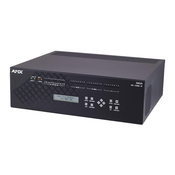
- all in a single box. FIG. 1 displays the DVX-3150HD-SP. Enova DVX-3150HD-SP FIG. 1 The Enova All-in-One Presentation Switchers covered in this manual include:... -
Page 13: Integrated Control
Overview Integrated Control The 3000-series DVX includes the equivalent of a NetLinx 3101 central controller. The 2000-series DVX includes the equivalent of a NetLinx 2100 central controller. All DVX models also include a front control panel for an added level of convenience. The DVX features standard RS-232, IR, digital I/O, and relay control ports for control over environment and third-party equipment. -
Page 14: Enova 315X All-In-One Presentation Switchers
Enova 315x All-in-One Presentation Switchers Enova 315x All-in-One Presentation Switchers DVX-3150HD/3155HD/3156HD Enova DVX-3150HD-SP FIG. 2 Specif ications The following table lists the specifications for the Enova 315x All-in-One Presentation Switchers: DVX-3150HD/3155HD/3156HD Specif ications Power: • 100-240V, 47/63 Hz AC supply Power Consumption: •... - Page 15 Enova 315x All-in-One Presentation Switchers DVX-3150HD/3155HD/3156HD Specif ications Navigational pushbuttons: 4 directional buttons for navigating the options in the Switch, Video, Audio, and Status menus (on the LCD display). STATUS pushbutton: Press to access the STATUS menu on the LCD display on which you can view system status and other system information.
- Page 16 Enova 315x All-in-One Presentation Switchers DVX-3150HD/3155HD/3156HD Specif ications PROGRAM Port: DB9 connector (male) connects to a DB9 serial port on a PC, for serial communication. This connection is used to configure system settings. NOTE: This port is not recommended for f irmware updates or large f ile transfers. Any large data- intensive operations are better handled via Ethernet.
-
Page 17: Enova 21Xx All-In-One Presentation Switchers
Enova 21xx All-in-One Presentation Switchers Enova 21xx All-in-One Presentation Switchers DVX-2150HD/2155HD/2110HD Enova DVX-2150HD-SP FIG. 3 Specif ications The following table lists the specifications for the Enova 21xx All-in-One Presentation Switchers: DVX-2150HD/2155HD/2110HD Specif ications Power: 100-240V, 47/63 Hz AC supply Power Consumption: •... - Page 18 Enova 21xx All-in-One Presentation Switchers DVX-2150HD/2155HD/2110HD Specif ications Navigational 4 directional buttons for navigating the options in the Switch, Video, Audio, and Status menus (on pushbuttons: the LCD display). STATUS pushbutton: Press to access the STATUS menu on the LCD display on which you can view system status and other system information.
- Page 19 Enova 21xx All-in-One Presentation Switchers DVX-2150HD/2155HD/2110HD Specif ications CONFIG DIP Switch: 8-position Master configuration DIP switch allows setting the Serial Programming port baud rate and on-board Master execution mode (PRD or normal). See the CONFIG DIP Switch section on page 41 for more information. PROGRAM Port: DB9 connector (male) connects to a DB9 serial port on a PC, for serial communication.
- Page 20 Enova 21xx All-in-One Presentation Switchers DVX-2150HD/2155HD/2110HD Specif ications Optional Accessories: • CC-DVI-5BNCM DVI to 5 BNC adapter cable (FG10-2170-08) • CC-DVI-RCA3M DVI to 3 Male RCA adapter cable for component and composite connections (FG10-2170-09) • CC-DVI-SVID DVI to S-Video adapter cable (FG10-2170-10) •...
-
Page 21: Installation
Installation Installation Overview This chapter provides information on installing a DVX into an equipment rack. Mounting the DVX into an Equipment Rack The DVX occupies three rack units in a standard equipment rack. The following steps apply to mounting the DVX. Discharge any static electricity from your body by touching a grounded metal object. -
Page 22: Wiring And Device Connections
Wiring and Device Connections Wiring and Device Connections Overview This chapter provides functional details for each item on the front and rear panel of the DVX. Wiring specifications are also provided, when applicable. FIG. 5 displays the front panel of the DVX-3150HD, DVX-3155HD, and DVX-3156HD: INPUT LED I/O LEDs RS232/422/485 LEDs Relay LEDs IR/Serial LEDs... - Page 23 Wiring and Device Connections The DVX-3155HD-SP features the same options on the rear panel as the DVX-3150HD-SP with the exception that two DXLink inputs appear in place of two of the HDMI inputs. FIG. 7 displays the rear panel of the DVX-3155HD-T: DXLINK INPUTS DVX-3155HD-SP Rear Panel FIG.
- Page 24 Wiring and Device Connections FIG. 10 displays the rear panel of the DVX-2150HD-SP. The DVX-2155HD-SP features the same options on the rear panel as the DVX-2150HD-SP with the exception that two DXLink inputs appear in place of two of the HDMI inputs. MULTI FORMAT VIDEO INPUTS S/PDIF Power...
-
Page 25: Front Panel Controls And Indicators
Wiring and Device Connections Front Panel Controls and Indicators The following sub-sections describe each component on the front panel of the DVX. Refer to FIG. 5 on page 22 for the component layout of the front panel. LEDs The LEDs on the front panel indicate the communications status of several different connections, as described in the table below: FIG. -
Page 26: Switch Pushbutton
Wiring and Device Connections The LCD Display also displays VIDEO menus (Video Output and Video Input), AUDIO menus (Audio Output, Audio Input, and Mic Input), SWITCH menu, and STATUS menu selections (see the Audio/Video Conf iguration section on page 52 for more information), and indicates current status of any adjustments made to settings within these menus. -
Page 27: Navigation Pushbuttons
Wiring and Device Connections Navigation Pushbuttons The four directional navigation buttons (Left/Right/Up/Down) enable you to navigate through and adjust the configurable parameters shown on the LCD display. The UP and DOWN navigation buttons are used to move between configurable parameters within a menu. -
Page 28: Video/Audio Mute Pushbuttons
Wiring and Device Connections VIDEO/AUDIO MUTE Pushbuttons Press the VIDEO MUTE button to enable or disable video on all output displays. Press the AUDIO MUTE button to enable or disable audio for all audio outputs. FIG. 23 displays the VIDEO/AUDIO MUTE pushbuttons. Press to toggle mute (blank) video all display outputs Press to toggle mute audio on all audio outputs Video/Audio Mute Pushbuttons... -
Page 29: Audio Inputs
Wiring and Device Connections The following table lists the number of digital audio ports and the port numbers for each model of DVX. Digital Audio Ports DVX Model HDMI Port Numbers No. of Port Numbers Ports DXLink Ports DVX-3150HD 5-10 DVX-3155HD 9-10 DVX-3156HD... -
Page 30: Mic Inputs
Wiring and Device Connections FIG. 27 provides details for wiring from an audio input to a an unbalanced source device that has RCA connectors. Positive and ground wires connect to the source. You also can use a CC-3.5ST5-RCA2F 2 RCA Female to 5-Pin Phoenix Cable (FG10-003-20) for this type of connection. -
Page 31: Amp Out
Wiring and Device Connections AMP OUT The AMP OUT amplified audio output (FIG. 30) differs according to the DVX model you are using: The 4-position captive wire connector for -SP models provides amplified, variable, mono or stereo audio output. The two 2-position captive wire connectors for -T models provide 70V or 100V mono amplified audio output. -
Page 32: S/Pdif Output
Wiring and Device Connections Destination devices require either balanced (differential) or unbalanced (single-ended) connections. FIG. 34 illustrates options for wiring between output connectors and the destinations. Destination Device Balanced Wiring Unbalanced Wiring Stereo 5-Terminal Wiring FIG. 34 WARNING: Do not connect the negative terminals to the source connector. Doing so can cause damage to your device. S/PDIF OUTPUT The S/PDIF OUTPUT provides digital S/PDIF audio output that can mirror any of the analog audio outputs or HDMI outputs. - Page 33 NOTE: The DVX and the adapter cables listed above utilize industry-standard pinouts. The only adapter cable that is unique to AMX is the CC-DVI-SVID (DVI-to-S-Video) cable. The others are generally available to purchase from other vendors, assuming that they also utilize industry standard (or equivalent) pinouts.
- Page 34 Wiring and Device Connections HDMI INPUTS The HDMI INPUT connectors on the rear panel are used to connect source input devices to the DVX. The DVX routes digital video and audio from connected source input devices to the connected output devices. These ports support HDMI (with 3D and Deep Color) and HDCP.
-
Page 35: Dxlink Inputs
Wiring and Device Connections DVI Input Adapter Cables Name Description Length HDMI Interface Cable HDMI Male to HDMI Male 6 1/2’ (2m) FG10-2178-05 HDMI to DVI Cable HDMI Male to DVI Male 6’ (1.828m) FG10-2179 (See the HDMI Male to DVI-D Male Cable section on page 51 for more information on HDMI-to-DVI cable wiring.) Supported Video Settings Type... -
Page 36: 21Xx Video Outputs
Wiring and Device Connections FIG. 40 displays the HDMI and DXLink audio/video output ports on the DVX-3150HD-SP. Video Outputs FIG. 40 NOTE: All video output ports support HDCP. 21xx Video Outputs The VIDEO OUTPUTS for the 21xx DVX models include 2 different types of connectors: 2 HDMI Output connectors (1-2) each provide scaled digital DVI video and HDMI audio and video output. -
Page 37: Twisted Pair Cable Pinouts
Wiring and Device Connections Twisted Pair Cable Pinouts AMX supports both the T568A and T568B pinout specifications for termination of the twisted pair cable used between the DVX and the DXLink receiver. Twisted Pair Cable Pinouts for T568A (Recommended) and T568B Specifications FIG. -
Page 38: Rear Panel Control And Power
Wiring and Device Connections Rear Panel Control and Power The following sub-sections describe each component on the rear panel of the DVX. Refer to FIG. 6 on page 22 for the component layout of the rear panel. RS232/422/485 Serial Port Connectors The RS232/422/485 serial device ports are used for A/V sources and displays. -
Page 39: Relays
Wiring and Device Connections RELAYS You can connect up to eight independent external relay devices to the Relay connectors on the device. When a relay is "OFF", terminals A and B are open-circuit. When a relay is "ON", terminals A and B are shorted together. The 315x DVX models feature eight connectors. -
Page 40: Ir/Serial
Wiring and Device Connections IR/SERIAL You can connect up to eight IR- or Serial-controllable devices to the IR/SERIAL connectors. FIG. 48 displays the IR/SERIAL connectors on the DVX-3150HD-SP. IR/Serial Connectors FIG. 48 The IR/SERIAL connectors accept an IR Emitter (CC-NIRC) that mounts onto the controlled device's IR window, or a mini- ... -
Page 41: Config Dip Switch
Wiring and Device Connections CONFIG DIP Switch Use the Configuration DIP switch to set the information used by the PROGRAM Port for communication or to set the on-board Master to Program Run Disable (PRD) mode. FIG. 49 displays the CONFIG DIP switch. Position 1 UP (ON) = PRD Mode Enabled Position 1 DOWN (OFF) = Normal (default) Mode - PRD Mode Disabled Switch Position 1 Sets PRD Mode (UP = ON) -
Page 42: Program Port
Wiring and Device Connections PROGRAM Port The PROGRAM port is a DB-9 male RS-232 port that connects the DVX to a communication port on a PC, and is intended primarily to be used to configure system settings. FIG. 50 displays the PROGRAM port. Program Port FIG. -
Page 43: Axlink Port And Led (4-Pin Captive-Wire)
LAN Connector / LEDs FIG. 54 AxLink Port and LED (4-pin captive-wire) The AxLink port (FIG. 55) allows the DVX to support AMX AxLink devices. FIG. 55 displays the AxLink port and LED. AxLink Port and LED FIG. 55 The (green) AxLink LED indicates AxLink data activity: Off - No power, or the controller is not functioning properly. -
Page 44: Power Connector/Switch/Fuse
Wiring and Device Connections FIG. 56 provides wiring requirements for the AxLink connector: To the Controller’s To the external AxLink device AxLink/PWR connector Top view Top view Mini-Phoenix Connector Wiring Diagram (Direct Data And Power) FIG. 56 To use the 4-pin 3.5 mm mini-Phoenix (female) captive-wire connector for data communication and power transfer, the incoming PWR and GND cable from the 12 VDC-compliant power supply must be connected to the AxLink cable connector going to the All-In- One Presentation Switcher. -
Page 45: Cable Details And Pinout Information
Cable Details and Pinout Information Cable Details and Pinout Information Overview The DVI-I Input connectors on the rear panel are used to connect video source input devices to the DVX (FIG. 59). The DVX routes video from connected source input devices to the connected output device. Each connector supports HDMI and DVI as well as VGA, S-Video, Composite, and Component inputs. -
Page 46: Dvi-D Male To Dvi-D Male Single-Link Cable
Cable Details and Pinout Information DVI-D Male to DVI-D Male Single-Link Cable Cable to be composed of the following: Four UL20276 (28AWG twisted pair + drain wire + aluminum foil/mylar shield) for TMDS signals and shields Five UL1589 (28AWG) for DDC_CLK, DDC_DATA, Hot_Plug_Detect, +5VDC, and GROUND ... -
Page 47: Dvi-A Male To 5-Bnc Male Cable
Five 75ohm 28 AWG mini-coax cables for the Red, Green, Blue, VSync, and HSync signals and returns EMI shield metal can on DVI connector Note: This cable type corresponds to the CC-DVI-5BNCM DVI-to-Component cable (FG10-2170-08), available from AMX. DVI-to-5-BNC Cable Pinout Information The following table lists DVI--to-5-BNC cable pinouts: DVI-to-5-BNC Cable Pinout Information... -
Page 48: Dvi-A Male To Triple Rca Male Cable
EMI shield metal can on DVI connector NOTE: This cable type corresponds to the CC-DVI-RCA3M DVI-to-Component/Composite cable (FG10-2170-09), available from AMX. DVI-to-Triple RCA Cable Pinout Information The following table lists the DVI-to-Triple RCA cable pinouts: DVI-to-Triple RCA Cable Pinout Information... -
Page 49: Dvi-A Male To S-Video Male Cable
Two 75ohm 28 AWG mini-coax cables for the Luminance (Y) and Chrominance (C) signals and returns EMI shield metal can on DVI connector NOTE: This cable corresponds to the CC-DVI-SVID DVI-to-S-Video adapter cable (FG10-2170-10), available from AMX. DVI-to-S-Video Cable Pinout Information The following table lists the DVI-to-S-Video cable pinouts: DVI-to-S-Video Cable Pinout Information... - Page 50 Cable Details and Pinout Information DVI-to-S-Video Cable Pinout Information BACKSHELL SHIELD Pin populated in DVI-A connector, but not connected for this cable Enova DVX-315xHD & DVX-215xHD All-in-One Presentation Switchers - Instruction Manual...
-
Page 51: Dvi-A Male To Hd15 (Vga) Male Adapter
EMI shield metal can on both DVI and HD15 connectors and connected to braid NOTE: This cable type corresponds to the CC-DVIM-VGAF DVI-to-VGA adapter (FG10-2170-13), available from AMX. DVI-to-VGA Cable Pinout Information The following table lists the DVI-to-VGA cable pinouts:... -
Page 52: Hdmi Male To Dvi-D Male Cable
Cable Details and Pinout Information HDMI Male to DVI-D Male Cable This section details the wiring for HDMI to DVI cabling. HDMI-to-DVI-D Cable Pinout Information The following table lists the HDMI-to-DVI-D cable pinouts: HDMI-to-DVI-D Cable Pinout Information HDMI DVI-D Notes: Connector Pin Signal Name Wire... -
Page 53: Audio/Video Configuration
Audio/Video Configuration Audio/Video Conf iguration Overview You can access the configuration settings for the DVX by using one of the following methods: Using the front panel buttons Using a Web browser Using the Front Panel Buttons You can access the configuration settings for the All-In-One Presentation Switcher by using the VIDEO MENU, AUDIO MENU, SWITCH, and STATUS buttons on the front panel of the DVX. - Page 54 Audio/Video Configuration Video Output Menu Options Logo/Test Use the left and right buttons to choose an output test pattern. Select Off to disable the test pattern and view video from the selected source. Select one of the following options: Color Bar, Gray Ramp, SMPTE Bar, HiLoTrak, Pluge, and Cross Hatch.
-
Page 55: Setting The Video Type For A Video Input
Audio/Video Configuration Video Input Menu Options Resolution Use the left and right buttons to select the correct resolution and refresh rate of the selected output. For a complete list of output resolutions, see the DVI and HDMI Supported Output Resolutions section on page 112. -
Page 56: Selecting A Video Test Pattern
Audio/Video Configuration Selecting a Video Test Pattern Selecting a test pattern for your input source can help determine if the displays are connected correctly. Perform these steps the select a test pattern: Press the VIDEO MENU button on the front panel of the DVX to open the Video Output menu. Press the left and right navigation buttons to select the output on which to display the test pattern. -
Page 57: Microphone Settings
Audio/Video Configuration Audio Input Menu Options Audio Input Use the left and right buttons to manually select which video input you want to use. Select any of the available Select audio inputs. Gain Use the left and right buttons to adjust the gain/attention level of the audio input. Set the gain from -24 to +24dB in 1dB increments. -
Page 58: Switch Menu
Audio/Video Configuration Switch Menu Press the SWITCH button to access the Switch menu for switching between the available audio and video devices. Use the UP and DOWN navigational buttons to scroll through the menu options. Use the RIGHT and LEFT navigational buttons to selected the desired input and output. -
Page 59: Dvx Webconsole
Audio/Video Configuration DVX WebConsole The DVX features an on-board WebConsole that allows you to configure the device and make various adjustments to audio/video and system settings. The WebConsole is accessed via a web browser on a PC that has network access to the DVX. The DVX WebConsole can be divided into two primary parts: Audio/Video Switcher Configuration Settings ... -
Page 60: Webconsole - Master Configuration Manager
Using a Web Browser You can access the configuration settings for the All-In-One Presentation Switcher by using a web browser. (AMX supports any industry-standard web browser running Adobe Flash Player 10 or better.) The system configuration pages are available by entering the IP address of the NetLinx master into the location bar of your web browser. -
Page 61: Locating The Ip Address Of The Dvx
Audio/Video Configuration Perform these steps to access the configuration settings: Open a web browser. Enter the IP address of the All-In-One Presentation Switcher in the location bar of the web browser. (If you do not know your switcher’s IP address, see the Locating the IP Address of the DVX section on page 60.) The Main WebControl page opens (FIG. -
Page 62: Video Settings
8192kb of flash memory available for storing the three image files. The amount of free space remaining appears on the screen. See the Uploading an Image File section on page 62 for more information. NOTE: Large images can cause a slowdown in performance. Though images up to 1920x1200 are supported, AMX recommends using an image size no greater than 640x480. -
Page 63: Uploading An Image File
Video Out tab. Images must be 24-bit color bitmap files at least 36x36 pixels in size. WARNING: Large images can cause a slowdown in performance. Though images up to 1920x1200 are supported, AMX recommends using an image size no greater than 640x480. - Page 64 Audio/Video Configuration 1 - Input: Select the corresponding option button to switch that video input to the selected output (see Select Output below). When you select an input, the other options on the page change to reflect the input’s current settings. You can only select one video input at a time.
-
Page 65: Audio Settings
Audio/Video Configuration Audio Settings The Audio page enables you to set the audio qualities for each audio input, microphone input, amplifier output, and line output. Any changes you make reflect instantaneously on your source input and output devices. Audio Out FIG. -
Page 66: Audio In/Microphone
Audio/Video Configuration 8 - Equalizer: The equalizer is a 10 band parametric equalizer enabling you to set any of the 10 default frequencies (31Hz, 62Hz, 125Hz, 250Hz, 500Hz, 1000Hz, 2000Hz, 4000Hz, 8000Hz, 16000Hz) to any value from 20Hz to 20KHz. Each band is set individually by selecting the band from the Band menu then adjusting the remaining settings. - Page 67 Audio/Video Configuration 4 - Input Gain: Use the slider to adjust the gain level of the audio input. You can set the gain from -24 to +24dB in 1dB increments. The default setting is 0. 5 - HDMI Audio: Use the menu to select the HDMI Audio type for the audio input. This option is not available if you select a mirrored input for the EDID Mode on the Video In tab.
-
Page 68: Setting Up Surround Audio
Audio/Video Configuration Setting Up Surround Audio To pass surround audio from HDMI inputs to HDMI or S/PDIF outputs you must have an HDMI sink (display, AVR, etc.) that supports one or more surround formats. Follow these steps to configure the DVX to pass-through surround audio. Connect a source that is capable of providing surround audio to an HDMI input on the DVX. -
Page 69: System Settings
NOTE: Due to the way many browsers manage f ile upload requests while in an authenticated session, it is not possible to load a DVX setup (.xdv) f ile with any web browser AMX has tested, except Microsoft Internet Explorer when HTTP Security is enabled on the DVX Master. -
Page 70: Netlinx Firmware Upgrades
Upgrading firmware on Enova DVX All-In-One Presentation Switchers involves downloading the latest firmware files from www.amx.com and using NetLinx Studio to transfer the files to a target DVX. The NetLinx Studio software application (available for free download from www.amx.com) provides the ability to transfer KIT firmware files to a NetLinx device such as the DVX. -
Page 71: Downloading The Latest Firmware Files From Www.amx.com
Downloading Enova DVX Firmware Files on www.amx.com Visit the appropriate product page on www.amx.com for the latest NI Master, Device Controller, and A/V Switcher/Scaler firmware (*.kit) files for your DVX. Firmware file links are available along the right-side of the catalog page (FIG. -
Page 72: Sending Firmware (*.Kit) Files To The Dvx
NOTE: A Kit f ile (*.KIT) is a package of several f iles, all of which are required to upgrade the f irmware, and are available online via www.amx.com. Firmware download links are provided in the relevant product page. The Online Device Tree (Online Tree tab of the Workspace Window) displays information about each online device, including ... -
Page 73: Additional Documentation
DVX, or change connections until the transfer is complete. Failure to complete this operation successfully may require a factory repair of the DVX. Additional Documentation For additional information on using NetLinx Studio, refer to the NetLinx Studio online help and Instruction Manual (available at www.amx.com). Enova DVX-315xHD & DVX-215xHD All-in-One Presentation Switchers - Instruction Manual... -
Page 74: Programming
Programming Programming Overview The chapter defines all programming commands available for the DVX. NOTE: This chapter lists programming commands unique to the DVX. Please consult the WebConsole & Programming Guide for NetLinx Integrated Controllers for more details on NetLinx controller commands. The DVX supports all commands compatible with the NI-3101-SIG. -
Page 75: Netlinx Channels And Levels
Programming NetLinx Channels and Levels The following sections define the NetLinx channels and levels available for the DVX. DVX-315x NetLinx Channels The following table lists the NetLinx channels for the 315x DVX models. DVX-315x NetLinx Channels Channel Ports Description Volume Up Volume Down Volume Mute Cycle Switches video input 1 to the video output specified in the DPS (see page 76 for details) -
Page 76: Dvx-21Xx Netlinx Channels
Programming DVX-315x NetLinx Channels 1-10 Video In Saturation Ramp Up 1-10 Video In Saturation Ramp Down 1-10 Video In Contrast Ramp Up 1-10 Video In Contrast Ramp Down 1-10 Video In Hue Ramp Up 1-10 Video In Hue Ramp Down Output Zoom Ramp Up Output Zoom Ramp Down Balance Ramp Up... -
Page 77: Channel Video Switching
Programming DVX-21xx NetLinx Channels Audio Input Gain Down Black and White State Audio Input Gain Mute (Reserved for future use) Audio Input Gain Mute Cycle (Reserved for future use) Video In Brightness Ramp Up (only applicable when routed to a scaled output) Video In Brightness Ramp Down (only applicable when routed to a scaled output) Video In Saturation Ramp Up (only applicable when routed to a scaled output) Video In Saturation Ramp Down (only applicable when routed to a scaled output) -
Page 78: Dvx-315X Netlinx Levels
Programming DVX-315x NetLinx Levels The following table list the NetLinx levels for the 315x DVX models: DVX-315x NetLinx Levels Level Ports Range Function 0-100 Output volume (-20)-(20) Audio Output Balance 1-14 (-24)-(24) Audio Input Gain Temperature (read-only level) 1-10 0-100 Input Video Brightness 1-10 0-100... -
Page 79: Dvx-21Xx Netlinx Levels
Programming DVX-21xx NetLinx Levels The following table list the NetLinx levels for the 21xx DVX models: DVX-21xx NetLinx Levels Level Ports Range Function 0-100 Output volume (-20)-(20) Audio Output Balance (-24)-(24) Audio Input Gain Temperature (read-only level) 0-100 Input Video Brightness 0-100 Input Video Saturation 0-100... -
Page 80: Send_Commands
Programming SEND_COMMANDS The commands listed in the following sections are for the switcher only. For generic NetLinx commands, see the NetLinx Integrated Controllers WebConsole and Programming Guide. The commands derive their input/output port addressing from the target D:P:S. INPUT ports range from 5-14 for Audio and from 1-10 for Video. HDMI inputs are capable of carrying both digital audio ... -
Page 81: Audio Send_Commands
Programming AUDIO SEND_COMMANDs The following table lists the audio SEND_COMMANDs available for the DVX: Audio SEND_COMMANDs AI<input>O<output> Switches audio input port <input> to audio output port <output>. Syntax: SEND_COMMAND "'AI<input>O<output>'" Variables: input = The source audio input number. output = The audio output port number to switch to. Example: SEND_COMMAND SWITCHER,"'AI2O1'"... -
Page 82: Audin_Compression_Release
Programming Audio SEND_COMMANDs ?AUDIN_COMPRESSION_RELEASE Requests the compression release for the specified audio port. Syntax: SEND_COMMAND <DEV>, "'?AUDIN_COMPRESSION_RELEASE'" Example: SEND_COMMAND AUDIO_1, "'?AUDIN_COMPRESSION_RELEASE'" Returns a COMMAND string of the form: AUDIN_COMPRESSION_RELEASE-<release> AUDIN_COMPRESSION_RELEASE Sets the duration of the compression release phase for the specified audio port. Syntax: SEND_COMMAND <DEV>, "'AUDIN_COMPRESSION_RELEASE-<release>'"... -
Page 83: Audin_Stereo
Programming Audio SEND_COMMANDs ?AUDIN_STEREO Requests the stereo setting (stereo/mono) of the specified audio input port. Syntax: SEND_COMMAND <DEV>, "'?AUDIN_STEREO'" Example: SEND_COMMAND AUDIO_INPUT_1,"'?AUDIN_STEREO'" Returns a COMMAND string of the form: AUDIN_STEREO-<setting>. AUDIN_STEREO Sets the stereo setting on the specified input port. If enabled, the stereo setting is on. -
Page 84: Audmic_Compression_Release
Programming Audio SEND_COMMANDs AUDMIC_COMPRESSION_RATIO Sets the compression ratio for the specified microphone port. Syntax: SEND_COMMAND <DEV>, "'AUDMIC_COMPRESSION_RATIO-<ratio>'" Variable: ratio = 1 to 20 Example: SEND_COMMAND MICROPHONE_1, "'AUDMIC_COMPRESSION_RATIO-5'" Sets the compression ratio for the microphone port (#1 based on the D:P:S) to 5. ?AUDMIC_COMPRESSION_RELEASE Requests the duration of the release phase while compressing for a specified microphone. -
Page 85: Audmic_Duck_Level
Programming Audio SEND_COMMANDs AUDMIC_DUCK_LEVEL Sets the ducking level for the specified microphone port. Syntax: SEND_COMMAND <DEV>, "'AUDMIC_DUCK_LEVEL-<level>'" Variable: level = 0 to 20 Example: SEND_COMMAND MICROPHONE_1, "'AUDMIC_DUCK_LEVEL-4'" Sets the ducking level for the microphone port (#1 based on the D:P:S) to 4. AUDMIC_DUCK_RELEASE Sets the ducking release for the specified microphone port. -
Page 86: Audmic_Eq_Gain
Programming Audio SEND_COMMANDs ?AUDMIC_EQ_GAIN Requests the gain on the microphone equalizer setting of band <band> for the specified microphone port. Syntax: SEND_COMMAND <DEV>, "'?AUDMIC_EQ_GAIN-<band>'" Variable: band = 1..3 on the microphone inputs. Example: SEND_COMMAND MIC_1,"'?AUDMIC_EQ_GAIN-1'" Returns a COMMAND string of the form: AUDMIC_EQ_GAIN-<band>,<value>. -
Page 87: Audmic_Gating
Programming Audio SEND_COMMANDs AUDMIC_GAIN Sets the gain of the specified microphone port to <gain>. Syntax: SEND_COMMAND <DEV>, "'AUDMIC_GAIN-<gain>'" Variable: gain = -24 to 24 in dB Example: SEND_COMMAND MICROPHONE_1, "'AUDMIC_GAIN-3'" Sets the gain for the microphone port (#1 based on the D:P:S) to 3dB. ?AUDMIC_GATING Requests the gating setting for the specified microphone. -
Page 88: Audmic_Gating_Release
Programming Audio SEND_COMMANDs AUDMIC_GATING_HOLD Sets the duration of the hold phase while gating for the specified microphone port. Syntax: SEND_COMMAND <DEV>, "'AUDMIC_GATING_HOLD-<hold>'" Variable: hold = 0 to 2000 Example: SEND_COMMAND MICROPHONE_1, "'AUDMIC_GATING_HOLD-200'" Sets the gating hold for the microphone port (#1 based on the D:P:S) to 200. ?AUDMIC_GATING_RELEASE Requests the duration of the release phase while gating from the specified microphone port. -
Page 89: Audmic_Limiter_Release
Programming Audio SEND_COMMANDs AUDMIC_LIMITER_ATTACK Sets the duration of the attack phase while limiting for the specified microphone port. Syntax: SEND_COMMAND <DEV>, "'AUDMIC_LIMITER_ATTACK-<attack>'" Variable: attack = 1 to 2000 Example: SEND_COMMAND MICROPHONE_1, "'AUDMIC_LIMITER_ATTACK-200'" Sets the limiter attack for the microphone port (#1 based on the D:P:S) to 200. ?AUDMIC_LIMITER_RELEASE Requests the duration of the release phase while limiting from the specified microphone port. -
Page 90: Audmic_Preamp_Gain
Programming Audio SEND_COMMANDs AUDMIC_PHANTOM_PWR Enables or disables phantom power for the specified microphone port. Syntax: SEND_COMMAND <DEV>, "'AUDMIC_PHANTOM_PWR-<setting>'" Variable: setting = on, off Example: SEND_COMMAND MICROPHONE_1, "'AUDMIC_PHANTOM_PWR-on'" Allows phantom power for the microphone port (#1 based on D:P:S). ?AUDMIC_PREAMP_GAIN Requests the pre-amplifier gain setting on the specified microphone. Syntax: SEND_COMMAND <DEV>, "'?AUDMIC_PREAMP_GAIN'"... -
Page 91: Audout_Duck_Attack
Programming Audio SEND_COMMANDs AUDOUT_DELAY Sets the delay for the specified audio port. Syntax: SEND_COMMAND <DEV>, "'AUDOUT_DELAY-<delay>'" Variable: delay = 0 to 200 in milliseconds Example: SEND_COMMAND AUDIO_OUTPUT_1, "'AUDOUT_DELAY-50'" Sets the delay for the audio output port (#1 based on D:P:S) to 50. AUDOUT_DUCK_ATTACK Sets the duration of the attack phase while ducking for the specified audio output port. -
Page 92: Audout_Ducking
Programming Audio SEND_COMMANDs ?AUDOUT_DUCKING Requests the ducking setting for the specified audio port. Syntax: SEND_COMMAND <DEV>, "'?AUDOUT_DUCKING'" Example: SEND_COMMAND AUDIO_OUTPUT_1, "'?AUDOUT_DUCKING'" Returns a COMMAND string of the form: AUDOUT_DUCKING-<setting> AUDOUT_DUCKING Sets the ducking for the specified audio port. Syntax: SEND_COMMAND <DEV>, "'AUDOUT_DUCKING-<setting>'" Variable: setting = off, low, medium, high, custom Example:... -
Page 93: Audout_Eq_Mode
Programming Audio SEND_COMMANDs AUDOUT_EQ_GAIN Sets the gain on a specific equalizer band on the specified audio output port. Syntax: SEND_COMMAND <DEV>, "'AUDOUT_EQ_GAIN-<band>,<value>'" Variables: band = 1..10 if on the audio output port. value = -12..12. The units are in dB. Example: SEND_COMMAND AUDIO_OUTPUT_1,"'AUDOUT_EQ_GAIN-1=8'"... -
Page 94: Audout_Minvol
Programming Audio SEND_COMMANDs AUDOUT_MAXVOL Sets the maximum volume for the specified audio port. Syntax: SEND_COMMAND <DEV>, "'AUDOUT_MAXVOL-<maximum>'" Variable: maximum = 0 to 100 in percent Example: SEND_COMMAND AUDIO_OUTPUT_1, "'AUDOUT_MAXVOL-75'" Sets the maximum for the audio output port (#1 based on D:P:S) to 75%. ?AUDOUT_MINVOL Requests the current minimum volume for the specified audio port. -
Page 95: Audout_Volume
Programming Audio SEND_COMMANDs AUDOUT_TESTTONE Sets the frequency (if any) of a test tone for the specified audio port. Syntax: SEND_COMMAND <DEV>, "'AUDOUT_TESTTONE-<frequency>'" Variable: frequency = off, 60Hz, 250Hz, 400Hz, 1KHz, 3KHz, 5KHz, 10KHz, PINK NOISE, WHITE NOISE Example: SEND_COMMAND AUDIO_OUTPUT_1, "'AUDOUT_TESTTONE-250Hz'" Sets a test tone of 250Hz to play for the audio output port (#1 based on D:P:S). -
Page 96: Spdifout_Audio
Programming Audio SEND_COMMANDs PHANTOM_PWR See the AUDMIC_PHANTOM_PWR section on page 89. ?SPDIFOUT_AUDIO Requests to which output the specified audio port is connected. Syntax: SEND_COMMAND <DEV>, "'?SPDIFOUT_AUDIO'" Example: SEND_COMMAND AUDIO_OUTPUT_1, "'?SPDIFOUT_AUDIO'" Returns a COMMAND string of the form: SPDIFOUT_AUDIO-<option> SPDIFOUT_AUDIO Sets the output to which the specified audio port is connected. Syntax: SEND_COMMAND <DEV>, "'SPDIFOUT_AUDIO-<option>'"... -
Page 97: Video Send_Commands
Programming Video SEND_COMMANDs The following table lists the video SEND_COMMANDs available for the DVX: Video SEND_COMMANDs CI<input>O<output> Switches both the audio and video input port to the output port. Syntax: SEND_COMMAND <DEV>, "'CI<input>O<output>'" Variables: input = The source input port number. output = The output port number to switch to. -
Page 98: Output
Programming Video SEND_COMMANDs ?OUTPUT Requests for the outputs connected to an input. If the input port is not connected to any output port then the reply will indicate this with an output port number of ZERO (0). Syntax: SEND_COMMAND <DEV>, "'?OUTPUT-<sl>,<input>'" Variables: sl = AUDIO, VIDEO, or ALL. -
Page 99: Vidin_Contrast
Programming Video SEND_COMMANDs ?VIDIN_CONTRAST Requests the input contrast of the specified video port. Syntax: SEND_COMMAND <DEV>, "'?VIDIN_CONTRAST'" Example: SEND_COMMAND VIDEO_INPUT_1,"'?VIDIN_CONTRAST'" Returns a COMMAND string of the form: VIDIN_CONTRAST-<value> VIDIN_CONTRAST Sets the input contrast of the specified video port to <value>. Syntax: SEND_COMMAND <DEV>, "'VIDIN_CONTRAST-<value>'"... -
Page 100: Vidin_Hdcp
Programming Video SEND_COMMANDs ?VIDIN_HDCP Queries the video input HDCP compliance setting of the specified video input port. Syntax: SEND_COMMAND <DEV>,"'?VIDIN_HDCP'" Example: SEND_COMMAND VIDEO_INPUT_1,"'?VIDIN_HDCP'" Returns a string of the form: VIDIN_STATUS-<ENABLE|DISABLE> VIDIN_HDCP Sets the video input HDCP compliance setting of the specified video input port. When VIDIN_HDCP is disabled, the addressed video input will appear to any source as not being HDCP compliant. -
Page 101: Vidin_Name
Programming Video SEND_COMMANDs VIDIN_HUE Sets the input hue of the specified video port to <value>. Syntax: SEND_COMMAND <DEV>, "'VIDIN_HUE-<value>'" Variables: value = 0..100 Example: SEND_COMMAND VIDEO_INPUT_1,"'VIDIN_HUE-50'" Sets the hue of video input port (#1 based on D:P:S) to 50. ?VIDIN_NAME Requests the input name of the specified video port. -
Page 102: Vidin_Res_Auto
Programming Video SEND_COMMANDs ?VIDIN_RES_AUTO Requests the status (enabled /disabled) of the auto resolution setting on the specified video input port. Syntax: SEND_COMMAND <DEV>, "'?VIDIN_RES_AUTO'" Example: SEND_COMMAND VIDEO_INPUT_1,"'?VIDIN_RES_AUTO'" Returns a COMMAND string of the form: VIDIN_RES_AUTO-<ENABLE|DISABLE> VIDIN_RES_AUTO Enables or disables the auto resolution detect setting on the specified video input port (sets whether the video input port is supposed to have its resolution auto-detected. -
Page 103: Vidout_Aspect_Ratio
Programming Video SEND_COMMANDs VIDIN_VSHIFT Sets the vertical shifting of the specified RGB video input port. to <value>. Syntax: SEND_COMMAND <DEV>, "'VIDIN_VSHIFT-<value>'" Variables: value = -10..10 Example: SEND_COMMAND "'VIDIN_VSHIFT-2'" Sets the vertical shifting of RGB video input port (#1 based on D:P:S) to 2 (shift upward). SEND_COMMAND "'VIDIN_VSHIFT--3'"... -
Page 104: Vidout_Contrast
Programming Video SEND_COMMANDs ?VIDOUT_CONTRAST Requests the contrast of the specified output video port. Syntax: SEND_COMMAND <DEV>, "'?VIDOUT_CONTRAST'" Example: SEND_COMMAND VIDEO_OUTPUT_1,"'?VIDOUT_CONTRAST'" Returns a COMMAND string of the form: VIDOUT_CONTRAST-<value> VIDOUT_CONTRAST Sets the contrast of the specified video output port to <value>. Syntax: SEND_COMMAND <DEV>, "'VIDOUT_CONTRAST-<value>'"... -
Page 105: Vidout_Mute
Programming Video SEND_COMMANDs ?VIDOUT_MUTE Requests to see if VIDEO mute is enabled or disabled. Syntax: SEND_COMMAND <DEV>, "'?VIDOUT_MUTE'" Example: SEND_COMMAND SWITCHER,"'?VIDOUT_MUTE'" Returns a COMMAND string of the form: VIDOUT_MUTE<ENABLE|DISABLE> VIDOUT_MUTE Enables or disables VIDEO video output display (mute). Syntax: SEND_COMMAND <DEV>,"'VIDOUT_MUTE-<ENABLE|DISABLE>'" Example: SEND_COMMAND SWITCHER,"'VIDOUT_MUTE-ENABLE'"... -
Page 106: Vidout_Osd_Pos
Programming Video SEND_COMMANDs ?VIDOUT_OSD_POS Requests the On Screen Display (OSD) position on the display connected to the specified video port. Syntax: SEND_COMMAND <DEV>, "'?VIDOUT_OSD_POS'" Example: SEND_COMMAND VIDEO_OUTPUT_1,"'?VIDOUT_OSD_POS'" Returns a COMMAND string of the form: VIDOUT_OSD_POS-<position> VIDOUT_OSD_POS Sets the On Screen Display (OSD) position on the display connected to the specified video port Variables: position = TOP LEFT, TOP RIGHT, BTM RIGHT, BTM LEFT Syntax:... -
Page 107: Vidout_Testpat
Programming Video SEND_COMMANDs ?VIDOUT_TESTPAT Requests the test pattern setting for the specified video output port. See VIDOUT_TESTPAT for the list of test patterns. Syntax: SEND_COMMAND <DEV>, "'?VIDOUT_TESTPAT'" Example: SEND_COMMAND VIDEO_OUTPUT_1,"'?VIDOUT_TESTPAT'" Returns a COMMAND string of the form: VIDOUT_TESTPAT-<pattern> VIDOUT_TESTPAT Sets the test pattern to display for the specified video output port. Syntax: SEND_COMMAND <DEV>, "'VIDOUT_TESTPAT-<pattern>'"... - Page 108 Programming Video SEND_COMMANDs VIDOUT_ZOOM Sets the zoom of the image on the specified video port to <value>. NOTE: Adjusting the video output zoom also adjusts the horizontal and vertical sizes of the video output. Syntax: SEND_COMMAND <DEV>, "'VIDOUT_ZOOM-<value>'" Variables: value = 25..800 Example: SEND_COMMAND VIDEO_OUTPUT_1,"'VIDOUT_ZOOM-100'"...
-
Page 109: Front Panel Send_Commands
Programming Front Panel SEND_COMMANDs The following table lists the front panel SEND_COMMANDs available for the DVX: Front Panel SEND_COMMANDs ?FP_LOCKOUT Requests the status of the front panel lockout. Syntax: SEND_COMMAND <DEV>, "'?FP_LOCKOUT'" Example: SEND_COMMAND SWITCHER,"'?FP_LOCKOUT'" Returns a COMMAND string of the form: FP_LOCKOUT-<ENABLE|DISABLE>... -
Page 110: System Send_Commands
Programming Front Panel SEND_COMMANDs INTENSITY_LEDS Sets the intensity of the lighting/brightness of the LED buttons that are part of the Front Panel. Syntax: SEND_COMMAND <DEV>, "'INTENSITY_LEDS-<intensity-value>'" Variable: intensity-value = An integer value in the range of 0-100 with 0 being no illumination and 100 being maximum illumination. -
Page 111: Appendix A - Input Resolutions
Appendix A - Input Resolutions Appendix A - Input Resolutions Available Pixel Display and Refresh Rates The available pixel display and refresh rates for the input devices on the DVX are listed in the following sections. DVI, HDMI, and VGA Supported Input Resolutions DVI, HDMI, and VGA Supported Input Resolutions Resolution Name Horizontal... -
Page 112: Composite And S-Video Supported Input Resolutions
Appendix A - Input Resolutions DVI, HDMI, and VGA Supported Input Resolutions 1280x960@85 1280 ü ü VESA DMT Resolution Name Horizontal Vertical Refresh HDMI & Comments Video Active Pixels Active (Hz) Support Standard Lines Support 1280x1024@60 1280 1024 ü ü VESA DMT 1280x1024@75 1280... -
Page 113: Appendix B - Output Resolutions
Appendix B - Output Resolutions Appendix B - Output Resolutions Available Pixel Display and Refresh Rates The available pixel display and refresh rates for the output devices on the DVX are listed in the following section. DVI and HDMI Supported Output Resolutions DVI and HDMI Supported Output Resolutions Resolution Name Horizontal Active... -
Page 114: Appendix C - Volume Attenuation Table
Appendix C - Volume Attenuation Table Appendix C - Volume Attenuation Table Overview Volume attenuation on the DVX is not set by percentage, like it was on earlier DVX models: On the DVX, the output volume slider changes .5dB per click, to provide a more subtle adjustment. Unity gain is at 88, so a setting of 100 is actually 6dB gain. - Page 115 Appendix C - Volume Attenuation Table Volume Attenuation Percent Decibels Percent Decibels -14.5 -46.0 -15.0 -51.0 -15.5 -56.0 -16.0 -61.0 -16.5 -66.0 -17.0 -71.0 -17.5 -76.0 -18.0 -81.0 -18.5 Infinity -19.0 Enova DVX-315xHD & DVX-215xHD All-in-One Presentation Switchers - Instruction Manual...
- Page 116 The AMX Warranty and Return Policy and related documents can be viewed/downloaded at www.amx.com. 3000 RESEARCH DRIVE, RICHARDSON, TX 75082 AMX.com | 800.222.0193 | 469.624.8000 | +1.469.624.7400 | fax 469.624.7153 AMX (UK) LTD, AMX by HARMAN - Unit C, Auster Road, Clifton Moor, York, YO30 4GD United Kingdom • +44 1904-343-100 • www.amx.com/eu/...
Need help?
Do you have a question about the Enova DVX-3150HD-SP and is the answer not in the manual?
Questions and answers