Table of Contents
Advertisement
Quick Links
I n s t r u c t i o n M a n u a l
Enova DVX-315xHD/21xxHD
All-in-One Presentation Switchers
DVX-3150HD-SP, DVX-3150HD-T, DVX-3155HD-SP, DVX-3155HD-
T, DVX-3156HD-SP, DVX-3156HD-T
DVX-2150HD-SP, DVX-2150HD-T, DVX-2155HD-SP
DVX-2155HD-T, DVX-2110HD-SP, DVX-2110HD-T
A l l - I n - O n e P r e s e n t a t i o n S w i t c h e r s
L a s t R e v i s e d : 1 1 / 0 6 / 2 0 1 4
Advertisement
Chapters
Table of Contents

Related Manuals for AMX Enova DVX-315 HD Series


Summary of Contents for AMX Enova DVX-315 HD Series
- Page 1 I n s t r u c t i o n M a n u a l Enova DVX-315xHD/21xxHD All-in-One Presentation Switchers DVX-3150HD-SP, DVX-3150HD-T, DVX-3155HD-SP, DVX-3155HD- T, DVX-3156HD-SP, DVX-3156HD-T DVX-2150HD-SP, DVX-2150HD-T, DVX-2155HD-SP DVX-2155HD-T, DVX-2110HD-SP, DVX-2110HD-T A l l - I n - O n e P r e s e n t a t i o n S w i t c h e r s L a s t R e v i s e d : 1 1 / 0 6 / 2 0 1 4...
- Page 2 AMX is not responsible for products returned without a valid RMA number. AMX is not liable for any damages caused by its products or for the failure of its products to perform. This includes any lost profits, lost savings, incidental damages, or consequential damages.
- Page 3 Important Safety Instructions Important Safety Instructions Please adhere to all of the following safety instructions: Read the instructions. Keep the instructions. Heed all warnings. Follow the instructions. Do not use this apparatus near water. Clean this apparatus only with a dry cloth. Do not block any ventilation openings.
- Page 4 Important Safety Instructions Enova DVX-315xHD & DVX-215xHD All-in-One Presentation Switchers - Instruction Manual...
-
Page 5: Table Of Contents
Table of Contents Table of Contents Important Safety Instructions ................a Overview ......................1 Common Application ....................2 Audio Processing ...................... 2 Integrated Control ....................2 Enova 315x All-in-One Presentation Switchers ...........3 DVX-3150HD/3155HD/3156HD................3 Specifications ......................3 Enova 21xx All-in-One Presentation Switchers ...........7 DVX-2150HD/2155HD/2110HD................ - Page 6 Table of Contents Rear Panel Video Inputs and Outputs ..............25 MULTI-FORMAT VIDEO INPUTS..................25 HDMI INPUTS ........................ 26 DXLink INPUTS......................28 VIDEO OUTPUTS ......................28 315x Video Outputs........................28 21xx Video Outputs........................29 Twisted Pair Cable Pinouts .................... 30 Important Twisted Pair Cabling Requirements and Recommendations ......
- Page 7 Overview ........................ 69 Before You Start ..................... 70 Verifying the Current Firmware Version ..............70 Downloading the Latest Firmware Files from www.amx.com ......... 71 Downloading Enova DVX Firmware Files on www.amx.com ......... 71 Required Order of Firmware Updates for DVX Controllers........... 71 Sending Firmware (*.KIT) Files to the DVX .............
- Page 8 Table of Contents DVX-21xx NetLinx Channels..................77 Channel Video Switching ......................78 Standby Mode .......................... 79 DVX-315x NetLinx Levels ....................80 DVX-21xx NetLinx Levels ....................81 SEND_COMMANDS....................82 AUDIO SEND_COMMANDs ..................83 AI<input>O<output>......................83 ?AUDIN_COMPRESSION......................83 AUDIN_COMPRESSION ......................83 ?AUDIN_COMPRESSION_ATTACK ..................83 AUDIN_COMPRESSION_ATTACK ..................
- Page 9 Table of Contents ?AUDMIC_GATING_ATTACK ....................91 AUDMIC_GATING_ATTACK ....................91 ?AUDMIC_GATING_DEPTH....................91 AUDMIC_GATING_DEPTH ..................... 91 ?AUDMIC_GATING_HOLD ..................... 91 AUDMIC_GATING_HOLD....................... 91 ?AUDMIC_GATING_RELEASE ....................92 AUDMIC_GATING_RELEASE ....................92 ?AUDMIC_GATING_THRESH....................92 AUDMIC_GATING_THRESH ....................92 ?AUDMIC_LIMITER......................... 92 AUDMIC_LIMITER ........................92 ?AUDMIC_LIMITER_ATTACK....................93 AUDMIC_LIMITER_ATTACK ....................93 ?AUDMIC_LIMITER_RELEASE....................
- Page 10 Table of Contents ?AUDOUT_STEREO ......................100 AUDOUT_STEREO........................ 100 ?AUDOUT_TESTTONE ......................100 AUDOUT_TESTTONE ......................101 ?AUDOUT_VOLUME ......................101 AUDOUT_VOLUME ......................101 ?GAIN ..........................101 GAIN ............................ 101 ?HDMIOUT_AUDIO ......................101 HDMIOUT_AUDIO........................ 101 ?HDMIOUT_EQ ........................102 HDMIOUT_EQ ........................102 ?INPUTEQ ..........................102 INPUTEQ ..........................
- Page 11 Table of Contents VIDIN_HUE........................... 108 ?VIDIN_NAME........................108 VIDIN_NAME........................108 ?VIDIN_PHASE ........................108 VIDIN_PHASE........................108 ?VIDIN_PREF_EDID ......................109 VIDIN_PREF_EDID........................ 109 ?VIDIN_RES_AUTO....................... 109 VIDIN_RES_AUTO ........................ 109 ?VIDIN_RES_REF ........................109 VIDIN_RES_REF ........................109 ?VIDIN_SATURATION ......................110 VIDIN_SATURATION ......................110 ?VIDIN_STATUS ........................110 ?VIDIN_VSHIFT........................110 VIDIN_VSHIFT ........................
- Page 12 Table of Contents VIDOUT_ZOOM ........................116 Front Panel SEND_COMMANDs ................117 ?FP_LOCKOUT ........................117 FP_LOCKOUT........................117 ?FP_LOCKTYPE ........................117 FP_LOCKTYPE........................117 ?INTENSITY_LCD........................117 INTENSITY_LCD ........................117 System SEND_COMMANDs.................. 118 ?DXLINK_ETH ........................118 DXLINK_ETH ........................118 ?DXLINK_IN_ETH ......................... 118 DXLINK_IN_ETH........................118 ?INTENSITY_LEDS ........................
-
Page 13: Overview
Overview Overview Enova All-In-One Presentation Switchers combine all of the components you need to control/automate any environment into a simple, flexible, comprehensive solution including control, analog and digital audio/video inputs, audio and video switching, video scaling, local and remote distribution, plus audio mixing, and amplification - all in a single box. FIG. -
Page 14: Common Application
Overview Common Application Enova DVX All-in-One Presentation Switchers are ideal solutions when used to simplify A/V control and distribution in sophisticated presentation environments and conference rooms, including those supporting audio and video conferencing. It also fits well in classrooms and auditoriums that need multiple displays, or video previewing. Audio Processing Enova DVX All-in-One Presentation Switchers feature built-in audio mixing and amplification that outputs two channels at 25 Watts each into 8-ohms after passing through a mixer and an integrated equalizer to accommodate the size,... -
Page 15: Enova 315X All-In-One Presentation Switchers
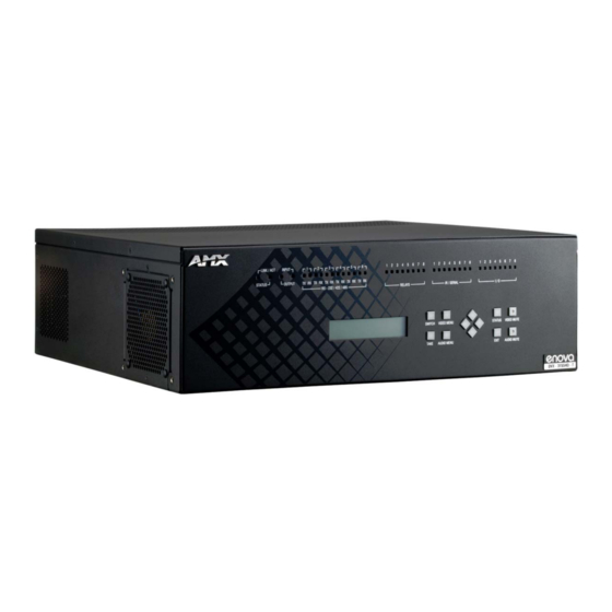
Enova 315x All-in-One Presentation Switchers Enova 315x All-in-One Presentation Switchers DVX-3150HD/3155HD/3156HD FIG. 1 Enova DVX-3150HD-SP Specifications The following table lists the specifications for the Enova 315x All-in-One Presentation Switchers: DVX-3150HD/3155HD/3156HD Specifications Power: 100-240V, 47/63 Hz AC supply Power Consumption: • 90 Watts typical without amplifier •... - Page 16 Enova 315x All-in-One Presentation Switchers DVX-3150HD/3155HD/3156HD Specifications (Cont.) SWITCH pushbutton: Press to access the Switch menu on the LCD display. Use the menu to choose to switch audio, video or both from any input to any output. TAKE pushbutton: While in the Switch menu, press to implement an audio/video switch. VIDEO MENU Press to access the Video menu on the LCD display.
- Page 17 Enova 315x All-in-One Presentation Switchers DVX-3150HD/3155HD/3156HD Specifications (Cont.) Rear Panel Components: (Cont.) HDMI INPUTS: • 6 HDMI inputs (5-10) receive digital audio and video from up to six video sources. (DVX- 3150HD only) • 4 HDMI inputs (5-8) receive digital audio and video from up to four video sources. (DVX- 3155HD only) •...
- Page 18 Enova 315x All-in-One Presentation Switchers DVX-3150HD/3155HD/3156HD Specifications (Cont.) Certifications: • FCC Part 15 Class A • IC CISPR 22 Class A • C-Tick CISPR 22 Class A • CE EN 55022 Class A and EN 55024 • LVD EN 60950-1 •...
-
Page 19: Enova 21Xx All-In-One Presentation Switchers
Enova 21xx All-in-One Presentation Switchers Enova 21xx All-in-One Presentation Switchers DVX-2150HD/2155HD/2110HD FIG. 1 Enova DVX-2150HD-SP Specifications The following table lists the specifications for the Enova 21xx All-in-One Presentation Switchers: DVX-2150HD/2155HD/2110HD Specifications Power: 100-240V, 47/63 Hz AC supply Power Consumption: • 80 Watts typical without amplifier •... - Page 20 Enova 21xx All-in-One Presentation Switchers DVX-2150HD/2155HD/2110HD Specifications (Cont.) VIDEO MENU Press to access the Video menu on the LCD display. There are two video menus (VIDEO pushbutton: OUTPUT and VIDEO INPUT) and both are accessible by using this button. Multiple presses cycle through the various VIDEO menus.
- Page 21 Enova 21xx All-in-One Presentation Switchers DVX-2150HD/2155HD/2110HD Specifications (Cont.) Rear Panel Components: (Cont.) HDMI INPUTS: • 4 HDMI inputs (3-6) receive digital audio and video from up to four video sources. (DVX-2150HD only) • 2 HDMI inputs (3-4) receive digital audio and video from up to two video sources. (DVX-2155HD and DVX-2110HD only) All HDMI inputs are HDCP compatible.
- Page 22 Enova 21xx All-in-One Presentation Switchers DVX-2150HD/2155HD/2110HD Specifications (Cont.) Certifications: • FCC Part 15 Class A • IC CISPR 22 Class A • C-Tick CISPR 22 Class A • CE EN 55022 Class A and EN 55024 • LVD EN 60950-1 •...
-
Page 23: Installation
Installation Installation Overview This chapter provides information on installing a DVX into an equipment rack. Mounting the DVX into an Equipment Rack The DVX occupies three rack units in a standard equipment rack. The following steps apply to mounting the DVX. Discharge any static electricity from your body by touching a grounded metal object. -
Page 24: Ventilation
Installation Ventilation ALWAYS ensure that the rack enclosure is adequately ventilated. Do not block any ventilation openings. Sufficient airflow must be achieved (by convection or forced-air cooling) to satisfy the ventilation requirements of all the items of equipment installed within the rack. Note: The maximum operating ambient temperature is 40°C (104°F). -
Page 25: Wiring And Device Connections
Wiring and Device Connections Wiring and Device Connections Overview This chapter provides functional details for each item on the front and rear panel of the DVX. Wiring specifications are also provided, when applicable. FIG. 2 displays the front panel of the DVX-3150HD, DVX-3155HD, and DVX-3156HD: INPUT LED I/O LEDs RS232/422/485 LEDs... - Page 26 Wiring and Device Connections FIG. 3 displays the rear panel of the DVX-3150HD-SP: MULTI FORMAT VIDEO INPUTS S/PDIF AUX AUDIO Power HDMI OUTPUT AUDIO INPUTS connector INPUTS OUTPUT OUTPUTS INPUTS LAN port INPUTS Config DIP I/O (Port 17) switch IR/SERIAL RS232/422/485 ports Ports (9-16) pushbutton...
- Page 27 Wiring and Device Connections FIG. 6 displays the front panel of the DVX-2150HD-SP and DVX-2155HD-SP: INPUT LED Relay IR/Serial RS232/422/485 LEDs LEDs LEDs I/O LEDs OUTPUT LED STATUS LED LINK/ACT LED SWITCH pushbutton VIDEO MUTE TAKE pushbutton AUDIO MUTE AUDIO MENU EXIT pushbutton LCD display STATUS pushbutton...
-
Page 28: Front Panel Controls And Indicators
Wiring and Device Connections FIG. 8 displays the rear panel of the DVX-2155HD-SP. DXLINK INPUTS FIG. 8 DVX-2155HD-SP rear panel FIG. 9 displays the rear panel of the DVX-2110HD-SP. FIG. 9 DVX-2110HD-SP rear panel Front Panel Controls and Indicators The following sub-sections describe each component on the front panel of the DVX. Refer to FIG. 2 on page 13 for the component layout of the front panel. -
Page 29: Lcd Display
Wiring and Device Connections Front Panel LEDs Label Color Description LINK/ACT green Blinks when receiving LAN data packets. STATUS green Blinks to indicate that the system is programmed and communicating properly. INPUT yellow Blinks to indicate that the Controller is receiving data. OUTPUT Blinks to indicate that the Controller is transmitting data. -
Page 30: Video Menu Pushbutton
Wiring and Device Connections VIDEO MENU Pushbutton Press the VIDEO MENU pushbutton to access the video options, displayed on the LCD display. There are two video menus (VIDEO OUTPUT and VIDEO INPUT) and both are accessible by using this button. Multiple presses cycle through the various VIDEO menus. -
Page 31: Navigation Pushbuttons
Wiring and Device Connections Navigation Pushbuttons The four directional navigation buttons (Left/Right/Up/Down) enable you to navigate through and adjust the configurable parameters shown on the LCD display. The UP and DOWN navigation buttons are used to move between configurable parameters within a menu. Pressing UP takes you to the previous configuration parameter. Pressing DOWN takes you to the next configuration parameter. -
Page 32: Video/Audio Mute Pushbuttons
Wiring and Device Connections VIDEO/AUDIO MUTE Pushbuttons Press the VIDEO MUTE button to enable or disable video on all output displays. Press the AUDIO MUTE button to enable or disable audio for all audio outputs. FIG. 20 displays the VIDEO/AUDIO MUTE pushbuttons. Press to toggle mute (blank) video all display outputs Press to toggle mute audio on all audio outputs FIG. -
Page 33: Hdmi Inputs
Wiring and Device Connections HDMI INPUTS The HDMI INPUT connectors on the rear panel routes digital audio (and video) from connected source input devices to the connected output devices. These inputs support the following audio formats: Supported Audio Formats SA-CD Dolby Digital Plus DST (as used in SA-CD) DVD-Audio... -
Page 34: Mic Inputs
Wiring and Device Connections Source devices require either balanced (differential) or unbalanced (single-ended) connections. FIG. 23 illustrates options for wiring between sources and input connectors. More than one option can be used in the same system. source device Balanced wiring Unbalanced wiring FIG. -
Page 35: Amp Out
Wiring and Device Connections FIG. 26 illustrates wiring connections between the DVX and a mono RCA output and an XLR output. RCA output XLR output FIG. 26 RCA (mono) and XLR output wiring AMP OUT The AMP OUT amplified audio output (FIG. 27) differs according to the DVX model you are using: ... -
Page 36: Audio Outputs
Wiring and Device Connections On -T models, connect a speaker to either the 70V or 100V terminals as displayed in FIG. 29. FIG. 29 Connecting speakers to the Amplified Audio output (-T models) AUDIO OUTPUTS The Line Level audio outputs provide balanced or unbalanced, mono or stereo line-level audio output. The 315x models each feature three audio outputs (ports 2-4). -
Page 37: Rear Panel Video Inputs And Outputs
Wiring and Device Connections Rear Panel Video Inputs and Outputs The following sub-sections describe each component on the rear panel of the DVX. All digital inputs and outputs on the DVX support HDCP. Refer to FIG. 3 on page 14 for the component layout of the rear panel. MULTI-FORMAT VIDEO INPUTS The MULTI-FORMAT VIDEO INPUT connectors on the rear panel are used to connect video source input devices to the DVX. -
Page 38: Hdmi Inputs
Note: The DVX and the adapter cables listed above utilize industry-standard pinouts. The only adapter cable that is unique to AMX is the CC-DVI-SVID (DVI-to-S-Video) cable. The others are generally available to purchase from other vendors, assuming that they also utilize industry standard (or equivalent) pinouts. - Page 39 Wiring and Device Connections The following table lists the number of video ports and the port numbers for each model of DVX. Digital Audio Ports DVX Model No. of HDMI Ports Port Numbers No. of DXLink Ports Port Numbers DVX-3150HD 5-10 DVX-3155HD 9-10...
-
Page 40: Dxlink Inputs
Wiring and Device Connections The following table displays the supported video settings for each type of input connection compatible with the HDMI INPUT connectors: Supported Video Settings Type Phase Shift Saturation Contrast Brightness ... -
Page 41: 21Xx Video Outputs
Wiring and Device Connections FIG. 37 displays the HDMI and DXLink audio/video output ports on the DVX-3150HD-SP. FIG. 37 VIDEO OUTPUTS Note: All video output ports support HDCP. 21xx Video Outputs The VIDEO OUTPUTS for the 21xx DVX models include 2 different types of connectors: ... -
Page 42: Twisted Pair Cable Pinouts
Wiring and Device Connections Twisted Pair Cable Pinouts AMX supports both the T568A and T568B pinout specifications for termination of the twisted pair cable used between the DVX and the DXLink receiver. FIG. 40 Twisted pair cable pinouts for T568A (recommended) and T568B specifications... -
Page 43: Rear Panel Control And Power
Wiring and Device Connections Rear Panel Control and Power The following sub-sections describe each component on the rear panel of the DVX. Refer to FIG. 3 on page 14 for the component layout of the rear panel. RS232/422/485 Serial Port Connectors The RS232/422/485 serial device ports are used for A/V sources and displays. -
Page 44: Relays
Wiring and Device Connections RELAYS You can connect up to eight independent external relay devices to the Relay connectors on the device. When a relay is "OFF", terminals A and B are open-circuit. When a relay is "ON", terminals A and B are shorted together. The 315x DVX models feature eight connectors. -
Page 45: Ir/Serial
Wiring and Device Connections IR/SERIAL You can connect up to eight IR- or Serial-controllable devices to the IR/SERIAL connectors. FIG. 45 displays the IR/SERIAL connectors on the DVX-3150HD-SP. FIG. 45 IR/SERIAL connectors The IR/SERIAL connectors accept an IR Emitter (CC-NIRC) that mounts onto the controlled device's IR window, or a mini-plug (CC-NSER) that connects to the controlled device's control jack. -
Page 46: Config Dip Switch
Wiring and Device Connections CONFIG DIP Switch Use the Configuration DIP switch to set the information used by the PROGRAM Port for communication or to set the on-board Master to Program Run Disable (PRD) mode. FIG. 46 displays the CONFIG DIP switch. Position 1 UP (ON) = PRD mode enabled Position 1 DOWN (OFF) = Normal (default) mode - PRD mode disabled Switch position 1 sets PRD mode (UP = ON) -
Page 47: Program Port
Wiring and Device Connections PROGRAM Port The PROGRAM port is a DB-9 male RS-232 port that connects the DVX to a communication port on a PC, and is intended primarily to be used to configure system settings. FIG. 47 displays the PROGRAM port. FIG. -
Page 48: Axlink Port And Led (4-Pin Captive-Wire)
FIG. 51 LAN connector / LEDs AxLink Port and LED (4-pin captive-wire) The AxLink port (FIG. 52) allows the DVX to support AMX AxLink devices. FIG. 52 displays the AxLink port and LED. FIG. 52 AxLink Port and LED The (green) AxLink LED indicates AxLink data activity: ... - Page 49 Wiring and Device Connections FIG. 53 provides wiring requirements for the AxLink connector: To the Controller’s To the external AxLink device AxLink/PWR connector Top view Top view FIG. 53 Mini-Phoenix connector wiring diagram (direct data and power) To use the 4-pin 3.5 mm mini-Phoenix (female) captive-wire connector for data communication and power transfer, the incoming PWR and GND cable from the 12 VDC-compliant power supply must be connected to the AxLink cable connector going to the All-In-One Presentation Switcher.
-
Page 50: Power Connector/Switch/Fuse
Wiring and Device Connections Power Connector/Switch/Fuse FIG. 55 displays the power switch and connector for the DVX. Power switch Fuse (2.5A) Power cable connector FIG. 55 Power Connector/Switch/Fuse WARNING! This unit should only have one source of incoming power. Using more than one source of power to the Controller can result in damage to the internal components and a possible burn out. -
Page 51: Cable Details And Pinout Information
Cable Details and Pinout Information Cable Details and Pinout Information Overview The DVI-I Input connectors on the rear panel are used to connect video source input devices to the DVX (FIG. 56). The DVX routes video from connected source input devices to the connected output device. Each connector supports HDMI and DVI as well as VGA, S-Video, Composite, and Component inputs. -
Page 52: Dvi-D Male To Dvi-D Male Single-Link Cable
Cable Details and Pinout Information DVI-D Male to DVI-D Male Single-Link Cable Cable to be composed of the following: Four UL20276 (28AWG twisted pair + drain wire + aluminum foil/mylar shield) for TMDS signals and shields Five UL1589 (28AWG) for DDC_CLK, DDC_DATA, Hot_Plug_Detect, +5VDC, and GROUND ... -
Page 53: Dvi-A Male To 5-Bnc Male Cable
Five 75ohm 28 AWG mini-coax cables for the Red, Green, Blue, VSync, and HSync signals and returns EMI shield metal can on DVI connector Note: This cable type corresponds to the CC-DVI-5BNCM DVI-to-Component cable (FG10-2170-08), available from AMX. DVI-to-5-BNC Cable Pinout Information The following table lists DVI--to-5-BNC cable pinouts: DVI-to-5-BNC Cable Pinout Information... -
Page 54: Dvi-A Male To Triple Rca Male Cable
EMI shield metal can on DVI connector Note: This cable type corresponds to the CC-DVI-RCA3M DVI-to-Component/Composite cable (FG10-2170-09), available from AMX. DVI-to-Triple RCA Cable Pinout Information The following table lists the DVI-to-Triple RCA cable pinouts: DVI-to-Triple RCA Cable Pinout Information... -
Page 55: Dvi-A Male To S-Video Male Cable
Two 75ohm 28 AWG mini-coax cables for the Luminance (Y) and Chrominance (C) signals and returns EMI shield metal can on DVI connector Note: This cable corresponds to the CC-DVI-SVID DVI-to-S-Video adapter cable (FG10-2170-10), available from AMX. DVI-to-S-Video Cable Pinout Information The following table lists the DVI-to-S-Video cable pinouts: DVI-to-S-Video Cable Pinout Information... -
Page 56: Dvi-A Male To Hd15 (Vga) Male Adapter
EMI shield metal can on both DVI and HD15 connectors and connected to braid Note: This cable type corresponds to the CC-DVIM-VGAF DVI-to-VGA adapter (FG10-2170-13), available from AMX. DVI-to-VGA Cable Pinout Information The following table lists the DVI-to-VGA cable pinouts:... -
Page 57: Hdmi Male To Dvi-D Male Cable
Cable Details and Pinout Information HDMI Male to DVI-D Male Cable This section details the wiring for HDMI to DVI cabling. HDMI-to-DVI-D Cable Pinout Information The following table lists the HDMI-to-DVI-D cable pinouts: HDMI-to-DVI-D Cable Pinout Information HDMI DVI-D Notes: Connector Pin Signal Name Wire TMDS Data 2+... - Page 58 Cable Details and Pinout Information Enova DVX-315xHD & DVX-215xHD All-in-One Presentation Switchers - Instruction Manual...
-
Page 59: Audio/Video Configuration
Audio/Video Configuration Audio/Video Configuration Overview You can access the configuration settings for the DVX by using one of the following methods: Using the front panel buttons Using a Web browser Using the Front Panel Buttons You can access the configuration settings for the All-In-One Presentation Switcher by using the VIDEO MENU, AUDIO MENU, SWITCH, and STATUS buttons on the front panel of the DVX. - Page 60 Audio/Video Configuration Video Output Menu Options (Cont.) Use the left and right buttons to select how video inputs should be displayed when the input and output aspect ratio do not match. Select one of the following options: • MAINTAIN: Maintains the input aspect ratio while filling the screen either vertically or horizontally. Black bars may appear above and below or to the left and right of the image.
- Page 61 Audio/Video Configuration The following table lists the Video Input menu options available by pressing the VIDEO MENU button twice from the main volume screen. Video Input Menu Options Input Select Use the left and right buttons to select which video input you want to use. Choose any available input from 1-10.
-
Page 62: Setting The Video Type For A Video Input
Audio/Video Configuration Setting the Video Type for a Video Input Each video input type must be set manually. Perform these steps to set the video type for a video input: Press the VIDEO MENU button on the front panel of the DVX two times to open the Video Input menu. Press the left and right navigation buttons to select the input to change. - Page 63 Audio/Video Configuration Audio Output Menu Options (Cont.) Mic2 Mix Use the left and right buttons to set the mix level of microphone 2 in the overall mix. Set the mix level from 0 to -100. The default setting is 0. HDMI Use the left and right buttons to indicate which analog audio output to embed in the selected HDMI output.
-
Page 64: Microphone Settings
Audio/Video Configuration Microphone Settings The following table lists the microphone options available on the LCD display by pressing the AUDIO MENU button on the front panel: Mic Input Menu Options Mic Input Mode Use the left and right buttons to select either Single Stereo to adjust both microphone inputs or Dual Mono Mode to adjust the microphone settings individually. -
Page 65: Switch Menu
Audio/Video Configuration Switch Menu Press the SWITCH button to access the Switch menu for switching between the available audio and video devices. Use the UP and DOWN navigational buttons to scroll through the menu options. Use the RIGHT and LEFT navigational buttons to selected the desired input and output. -
Page 66: Dvx Webconsole
Audio/Video Configuration DVX WebConsole The DVX features an on-board WebConsole that allows you to configure the device and make various adjustments to audio/video and system settings. The WebConsole is accessed via a web browser on a PC that has network access to the DVX. -
Page 67: Master Controller Configuration Options
Master Configuration Manager - Additional Documentation For a full description of all Master Configuration pages, refer to the NI & DVX Central Controllers WebConsole & Programming Guide, available at www.amx.com. Enova DVX-315xHD & DVX-215xHD All-in-One Presentation Switchers - Instruction Manual... -
Page 68: Using A Web Browser
Audio/Video Configuration Using a Web Browser You can access the configuration settings for the All-In-One Presentation Switcher by using a web browser. (AMX supports any industry-standard web browser running Adobe Flash Player 10 or better.) The system configuration pages are available by entering the IP address of the NetLinx master into the location bar of your web browser. Entering your IP address into your web browser opens the Main WebControl page (FIG. -
Page 69: General Options
Audio/Video Configuration General Options The WebConsole Configuration page contains settings that are accessible from each tab. FIG. 62 indicates the universally accessible options available on the web pages. Reset to Defaults Amp Volume and Mute Refresh FIG. 62 WebConsole Configuration page Note: The number of available video and audio inputs and outputs vary depending upon which DVX model you are configuring. -
Page 70: Video Settings
Audio/Video Configuration Video Settings The Video Out tab enables you to set the resolution, aspect ratio, and picture qualities of each individual video input. Any changes you make reflect instantaneously on your source input and output devices. Video Out FIG. 63 displays the Video Out page for the DVX. FIG. -
Page 71: Uploading An Image File
See the Uploading an Image File section on page 59 for more information. Note: Large images can cause a slowdown in performance. Though images up to 1920x1200 are supported, AMX recommends using an image size no greater than 640x480. -
Page 72: Video In
Audio/Video Configuration Video In FIG. 64 displays the Video In tab on the Video page. The Video In tab enables you to set the resolution, aspect ratio, and picture qualities of each individual video input. Any changes you make reflect instantaneously on your source input and output devices. -
Page 73: Audio Settings
Audio/Video Configuration 6 - EDID Mode: Use the menus to indicate the desired EDID information to be sent to the selected video source. You can choose from one of the built-in EDID files which includes All Resolutions, only Full Screen Resolutions, or only Wide Screen Resolutions, or you can choose to mirror the EDID received from any connected display. - Page 74 Audio/Video Configuration 2 - Output Volume: Use the sliders to set the output levels for the selected audio output. You can set the following options for each audio output: Output Volume: Use the slider to set the volume of the selected audio output. You can set the volume from 0 to 100. The default setting is 20.
-
Page 75: Audio In/Microphone
Audio/Video Configuration Audio In/Microphone FIG. 66 displays the Audio In/Microphone page for the DVX. FIG. 66 WebConsole Configuration page - Audio In/Microphone tab 1 - Audio Input: Select the corresponding option button to switch that audio signal to the selected output. You can only select one audio input at a time. - Page 76 Audio/Video Configuration 8 - Microphone Adjustment: There are two separate sections for configuring Mic 1 and Mic 2. If you select Single Stereo for the Microphone Mode, there is a single configuration that affects both microphones. Selecting Dual Mono allows independent configuration of each mic. You can set the following options for each microphone: PreAmp Gain: Use the slider to set the preamp gain level for the mic.
-
Page 77: Setting Up Surround Audio
Audio/Video Configuration Setting Up Surround Audio To pass surround audio from HDMI inputs to HDMI or S/PDIF outputs you must have an HDMI sink (display, AVR, etc.) that supports one or more surround formats. Follow these steps to configure the DVX to pass-through surround audio. -
Page 78: Mixing Microphones Onto Analog And Hdmi Outputs
Audio/Video Configuration Mixing Microphones onto Analog and HDMI Outputs Follow these steps to connect and mix audio from a microphone input onto the source audio being routed to an audio output. The Mic inputs can accept both Microphone level and Line level audio. Connect an audio source to one of the microphone inputs on the DVX. -
Page 79: System Settings
Note: Due to the way many browsers manage file upload requests while in an authenticated session, it is not possible to load a DVX setup (.xdv) file with any web browser AMX has tested, except Microsoft Internet Explorer when HTTP Security is enabled on the DVX Master. - Page 80 Audio/Video Configuration Enova DVX-315xHD & DVX-215xHD All-in-One Presentation Switchers - Instruction Manual...
-
Page 81: Netlinx Firmware Upgrades
Upgrading firmware on Enova DVX All-In-One Presentation Switchers involves downloading the latest firmware files from www.amx.com and using NetLinx Studio to transfer the files to a target DVX. The NetLinx Studio software application (available for free download from www.amx.com) provides the ability to transfer KIT firmware files to a NetLinx device such as the DVX. -
Page 82: Before You Start
Verify you have the latest version of NetLinx Studio on your PC. Use the Web Update option in NetLinx Studio’s Help menu to obtain the latest version. Alternatively, go to www.amx.com and login as a Dealer to download the latest version. -
Page 83: Downloading The Latest Firmware Files From Www.amx.com
Downloading Enova DVX Firmware Files on www.amx.com Visit the appropriate product page on www.amx.com for the latest NI Master, Device Controller, and A/V Switcher/Scaler firmware (*.kit) files for your DVX. Firmware file links are available along the right-side of the catalog page (FIG. -
Page 84: Sending Firmware (*.Kit) Files To The Dvx
DVX use KIT files for firmware upgrades. Note: A Kit file (*.KIT) is a package of several files, all of which are required to upgrade the firmware, and are available online via www.amx.com. Firmware download links are provided in the relevant product page. ... - Page 85 NetLinx Firmware Upgrades Click the Browse (...) button to navigate to the target directory in the Browse For Folder dialog box (FIG. 71). FIG. 71 Browse For Folder dialog box (NetLinx Studio) The selected directory path is displayed in the Send To NetLinx Device dialog (Location text box). ...
-
Page 86: Additional Documentation
DVX. Additional Documentation For additional information on using NetLinx Studio, refer to the NetLinx Studio online help and Instruction Manual (available at www.amx.com). Enova DVX-315xHD & DVX-215xHD All-in-One Presentation Switchers - Instruction Manual... -
Page 87: Programming
Programming Programming Overview The chapter defines all programming commands available for the DVX. Note: This chapter lists programming commands unique to the DVX. Please consult the WebConsole & Programming Guide for NetLinx Integrated Controllers for more details on NetLinx controller commands. The DVX supports all commands compatible with the NI-3101-SIG. -
Page 88: Netlinx Channels And Levels
Programming NetLinx Channels and Levels The following sections define the NetLinx channels and levels available for the DVX. DVX-315x NetLinx Channels The following table lists the NetLinx channels for the 315x DVX models. DVX-315xNetLinx Channels Channel Ports Description Volume Up Volume Down Volume Mute Cycle Switches video input 1 to the video output specified in the DPS (see page 78 for details) -
Page 89: Dvx-21Xx Netlinx Channels
Programming DVX-315x NetLinx Channels (Cont.) Channel Ports Description 1-14 Gain Mute 1-14 Gain Cycle 1-10 Video In Brightness Ramp Up 1-10 Video In Brightness Ramp Down 1-10 Video In Saturation Ramp Up 1-10 Video In Saturation Ramp Down 1-10 Video In Contrast Ramp Up 1-10 Video In Contrast Ramp Down 1-10... -
Page 90: Channel Video Switching
Programming DVX-21xx NetLinx Channels (Cont.) Channel Ports Description Video Output Enable Mic Enable Video In Phase Ramp Up Video In Phase Ramp Down Standby State. See the Standby Mode on page 79 for more information. Video In V-Shift Ramp Up (only applicable when routed to a scaled output) Video In V-Shift Ramp Down Video In H-Shift Ramp Up Video In H-Shift Ramp Down... -
Page 91: Standby Mode
Programming Standby Mode Standby Mode can be activated via channel 100 on the DVX. The following points apply to Standby Mode on the DVX: After exiting Standby Mode, the DVX cannot re-enter Standby Mode for a period of 20 seconds. Any attempt to re-enter standby mode within this 20 second window is ignored. -
Page 92: Dvx-315X Netlinx Levels
Programming DVX-315x NetLinx Levels The following table list the NetLinx levels for the 315x DVX models: DVX-315x NetLinx Levels Level Ports Range Function 0-100 Output volume (-20)-(20) Audio Output Balance 1-14 (-24)-(24) Audio Input Gain Temperature (read-only level) 1-10 0-100 Input Video Brightness 1-10 0-100... -
Page 93: Dvx-21Xx Netlinx Levels
Programming DVX-21xx NetLinx Levels The following table list the NetLinx levels for the 21xx DVX models: DVX-21xx NetLinx Levels Level Ports Range Function 0-100 Output volume (-20)-(20) Audio Output Balance (-24)-(24) Audio Input Gain Temperature (read-only level) 0-100 Input Video Brightness 0-100 Input Video Saturation 0-100... -
Page 94: Send_Commands
Programming SEND_COMMANDS The commands listed in the following sections are for the switcher only. For generic NetLinx commands, see the NetLinx Integrated Controllers WebConsole and Programming Guide. The commands derive their input/output port addressing from the target D:P:S. INPUT ports range from 5-14 for Audio and from 1-10 for Video. -
Page 95: Audio Send_Commands
Programming AUDIO SEND_COMMANDs The following table lists the audio SEND_COMMANDs available for the DVX: Audio SEND_COMMANDs AI<input>O<output> Switches audio input port <input> to audio output port <output>. Syntax: SEND_COMMAND "'AI<input>O<output>'" Variables: input = The source audio input number. output = The audio output port number to switch to. Example: SEND_COMMAND SWITCHER,"'AI2O1'"... -
Page 96: Audin_Compression_Ratio
Programming Audio SEND_COMMANDs (Cont.) AUDIN_COMPRESSION_RATIO Sets the compression ratio for the specified audio input port. Syntax: SEND_COMMAND <DEV>, "'AUDIN_COMPRESSION_RATIO-<ratio>'" Variable: ratio = 1 to 20 Example: SEND_COMMAND AUDIO_INPUT_1, "'AUDIN_COMPRESSION_RATIO-5'" ?AUDIN_COMPRESSION_RELEASE Requests the compression release for the specified audio port. Syntax: SEND_COMMAND <DEV>, "'?AUDIN_COMPRESSION_RELEASE'"... -
Page 97: Audin_Digital
Programming Audio SEND_COMMANDs (Cont.) AUDIN_DIGITAL Sets the format for the specified audio input port. Syntax: SEND_COMMAND <DEV>, "'AUDIN_DIGITAL-<format>'" Variable: format = LPCM, AC3, DTS, MPEG, AAC Example: SEND_COMMAND AUDIO_INPUT_1, "'AUDIN_DIGITAL-AAC'" Sets the audio format for the audio input port (#1 based on D:P:S) to AAC. ?AUDIN_GAIN Requests the gain of the specified audio port. -
Page 98: Audmic_Compression
Programming Audio SEND_COMMANDs (Cont.) AUDMIC_COMPRESSION Sets the compression setting for the specified microphone to <setting>. Syntax: SEND_COMMAND <DEV>, "'AUDMIC_COMPRESSION-<setting>'" Variable: setting = off, low, medium, high, custom Example: SEND_COMMAND MICROPHONE_1, "'AUDMIC_COMPRESSION-high'" Sets the compression for the microphone port (#1 based on D:P:S) to high. ?AUDMIC_COMPRESSION_ATTACK Requests the duration of the attack phase while compressing for a specified microphone. -
Page 99: Audmic_Compression_Release
Programming Audio SEND_COMMANDs (Cont.) AUDMIC_COMPRESSION_RELEASE Sets the duration of the release phase while compressing for the specified microphone port. Syntax: SEND_COMMAND <DEV>, "'AUDMIC_COMPRESSION_RELEASE-<release>'" Variable: release = 1 to 5000 Example: SEND_COMMAND MICROPHONE_1, "'AUDMIC_COMPRESSION_RELEASE- 200'" Sets the compression release for the microphone port (#1 based on the D:P:S) to 200. -
Page 100: Audmic_Duck_Level
Programming Audio SEND_COMMANDs (Cont.) AUDMIC_DUCK_LEVEL Sets the ducking level for the specified microphone port. Syntax: SEND_COMMAND <DEV>, "'AUDMIC_DUCK_LEVEL-<level>'" Variable: level = 0 to 20 Example: SEND_COMMAND MICROPHONE_1, "'AUDMIC_DUCK_LEVEL-4'" Sets the ducking level for the microphone port (#1 based on the D:P:S) to 4. AUDMIC_DUCK_RELEASE Sets the ducking release for the specified microphone port. -
Page 101: Audmic_Eq_Ft
Programming Audio SEND_COMMANDs (Cont.) AUDMIC_EQ_FT Sets the filter type on a specific band of the equalizer for the specified microphone port. Syntax: SEND_COMMAND <DEV>, "'AUDMIC_EQ_FT-<band>,<type>'" Variables: band = 1..3 on the microphone inputs. type = bell, band pass, band stop, high pass, low pass, treble shelf, bass shelf Example: SEND_COMMAND MICROPHONE_1, "'AUDMIC_EQ_FT-1,band pass'"... -
Page 102: Audmic_Eq_Q
Programming Audio SEND_COMMANDs (Cont.) AUDMIC_EQ_Q Sets the quality factor (Q) for a specific band of the equalizer for the specified microphone port. Syntax: SEND_COMMAND <DEV>, "'AUDMIC_EQ_Q-<band>,<factor>'" Variables: band = 1 to 3 on the microphone inputs. factor = range depends on filter type (set by AUDMIC_EQ_FT, see page 88) Bell: range is 0.1 - 20.0 Band Pass:range is 0.1 - 20.0 Band Stop:range is 0.1 - 20.0... -
Page 103: Audmic_Gating_Attack
Programming Audio SEND_COMMANDs (Cont.) ?AUDMIC_GATING_ATTACK Requests the duration of the attack phase while gating for the specified microphone port. Syntax: SEND_COMMAND <DEV>, "'?AUDMIC_GATING_ATTACK'" Example: SEND_COMMAND MIC_1, "'?AUDMIC_GATING_ATTACK'" Returns a string of the form: ?AUDMIC_GATING_ATTACK=<value> AUDMIC_GATING_ATTACK Sets the gating attack for the specified microphone port. Syntax: SEND_COMMAND <DEV>, "'AUDMIC_GATING_ATTACK-<attack>'"... -
Page 104: Audmic_Gating_Release
Programming Audio SEND_COMMANDs (Cont.) ?AUDMIC_GATING_RELEASE Requests the duration of the release phase while gating from the specified microphone port. Syntax: SEND_COMMAND <DEV>, "'?AUDMIC_GATING_RELEASE'" Example: SEND_COMMAND MIC_1, "'?AUDMIC_GATING_RELEASE'" Returns a string of the form: ?AUDMIC_GATING_RELEASE=<value> AUDMIC_GATING_RELEASE Sets the duration of the release phase while gating from the specified microphone port. -
Page 105: Audmic_Limiter_Attack
Programming Audio SEND_COMMANDs (Cont.) ?AUDMIC_LIMITER_ATTACK Requests the duration of the attack phase while limiting from the specified microphone port. Syntax: SEND_COMMAND <DEV>, "'?AUDMIC_LIMITER_ATTACK'" Example: SEND_COMMAND MIC_1, "'?AUDMIC_LIMITER_ATTACK'" Returns a string of the form: ?AUDMIC_LIMITER_ ATTACK=< value> AUDMIC_LIMITER_ATTACK Sets the duration of the attack phase while limiting for the specified microphone port. -
Page 106: Audmic_Limiter_Thresh
Programming Audio SEND_COMMANDs (Cont.) AUDMIC_LIMITER_THRESH Sets the limiter threshold for the specified microphone port. Syntax: SEND_COMMAND <DEV>, "'AUDMIC_LIMITER_THRESH-<thresh>'" Variable: thresh = 0 to -60 Example: SEND_COMMAND MICROPHONE_1, "'AUDMIC_LIMITER_THRESH--20'" Sets the limiter threshold for the microphone port (#1 based on the D:P:S) to -20. -
Page 107: Audmic_Preamp_Gain
Programming Audio SEND_COMMANDs (Cont.) AUDMIC_PREAMP_GAIN Sets the pre-amplifier gain on the specified microphone. Syntax: SEND_COMMAND <DEV>, "'AUDMIC_PREAMP_GAIN-<gain>'" Variables: gain = 0-100. The units are in %. Example: SEND_COMMAND MIC_1,"'AUDMIC_PREAMP_GAIN-50'" Sets the pre-amplifier gain for the microphone port (#1 based on D:P:S) to 50%. -
Page 108: Audout_Delay
Programming Audio SEND_COMMANDs (Cont.) AUDOUT_DELAY Sets the delay for the specified audio port. Syntax: SEND_COMMAND <DEV>, "'AUDOUT_DELAY-<delay>'" Variable: delay = 0 to 200 in milliseconds Example: SEND_COMMAND AUDIO_OUTPUT_1, "'AUDOUT_DELAY-50'" Sets the delay for the audio output port (#1 based on D:P:S) to 50. AUDOUT_DUCK_ATTACK Sets the duration of the attack phase while ducking for the specified audio output port. -
Page 109: Audout_Duck_Thresh
Programming Audio SEND_COMMANDs (Cont.) AUDOUT_DUCK_THRESH Individually sets the ducking thresholds of both microphone ports for the specified audio port. Syntax: SEND_COMMAND <DEV>, "'AUDOUT_DUCK_THRESH-<mic1_thresh>'" Variables: mic1_thresh = -60 to 0 Example: SEND_COMMAND AUDIO_OUTPUT_1, "'AUDOUT_DUCK_THRESH--12'" Sets the two microphone thresholds for the audio output port (#1 based on D:P:S) to -12. -
Page 110: Audout_Eq_Ft
Programming Audio SEND_COMMANDs (Cont.) AUDOUT_EQ_FT Sets the filter type on a specific equalizer band on the specified audio output port. Syntax: SEND_COMMAND <DEV>, "'AUDOUT_EQ_FT-<band>=<filter type>'" Variables: band = 1..10 if on the audio output port. filter type = Bell, Band Pass, Band Stop, High Pass, Low Pass, Treble Shelf, and Bass Shelf Example: SEND_COMMAND AUDIO_OUTPUT_1,"'AUDOUT_EQ_FT-1=Low Pass'"... -
Page 111: Audout_Eq_Q
Programming Audio SEND_COMMANDs (Cont.) ?AUDOUT_EQ_Q Requests the quality factor (Q) on a specific equalizer band on the specified audio output port. Syntax: SEND_COMMAND <DEV>, "'?AUDOUT_EQ_Q-<band>'" Example: SEND_COMMAND AUDIO_OUTPUT_1,"'?AUDOUT_EQ_Q-1'" Returns a COMMAND string of the form: AUDOUT_EQ_Q-<band>,<factor> AUDOUT_EQ_Q Sets the quality factor (Q) on a specific equalizer band on the specified audio output port. -
Page 112: Audout_Minvol
Programming Audio SEND_COMMANDs (Cont.) AUDOUT_MINVOL Sets the minimum volume for the specified audio port. Syntax: SEND_COMMAND <DEV>, "'AUDOUT_MINVOL-<minimum>'" Variable: minimum = 0 to 100 in percent. Example: SEND_COMMAND AUDIO_OUTPUT_1, "'AUDOUT_MINVOL-5'" Sets the minimum for the audio output port (#1 based on D:P:S) to 5%. ?AUDOUT_MUTE Requests audio mute status. - Page 113 Programming Audio SEND_COMMANDs (Cont.) AUDOUT_TESTTONE Sets the frequency (if any) of a test tone for the specified audio port. Syntax: SEND_COMMAND <DEV>, "'AUDOUT_TESTTONE-<frequency>'" Variable: frequency = off, 60Hz, 250Hz, 400Hz, 1KHz, 3KHz, 5KHz, 10KHz, PINK NOISE, WHITE NOISE Example: SEND_COMMAND AUDIO_OUTPUT_1, "'AUDOUT_TESTTONE-250Hz'" Sets a test tone of 250Hz to play for the audio output port (#1 based on D:P:S).
- Page 114 Programming Audio SEND_COMMANDs (Cont.) ?HDMIOUT_EQ Requests the status of the HDMI equalizer for the specified audio port. Syntax: SEND_COMMAND <DEV>, "'?HDMIOUT_EQ'" Example: SEND_COMMAND AUDIO_OUTPUT_1, "'?HDMIOUT_EQ'" Returns a COMMAND string of the form: HDMIOUT_EQ-<option> HDMIOUT_EQ Enables or disables the HDMI equalizer for the specified audio port. Syntax: SEND_COMMAND <DEV>, "'HDMIOUT_EQ-<option>'"...
- Page 115 Programming Audio SEND_COMMANDs (Cont.) XPOINT Sets the mix level that the audio input addressed by the parameter <input> provides to the audio output <output> to <value>. Note: Audio input ports 1..10 share a setting across them for a specific output mixer's value.
- Page 116 Programming Video SEND_COMMANDs (Cont.) ?INPUT Requests for the input connected to an output. Normally, if the output port is not connected to any input port then the reply will indicate this with an input port number of ZERO (0). For the DVX products, at this time, the output parameter is ignored and assumed to be 1.
- Page 117 Programming Video SEND_COMMANDs (Cont.) VIDIN_BRIGHTNESS Sets the input brightness of the specified video port to <value>. Syntax: SEND_COMMAND <DEV>, "'VIDIN_BRIGHTNESS-<value>'" Variables: value = 0..100 Example: SEND_COMMAND VIDEO_INPUT_1,"'VIDIN_BRIGHTNESS-50'" Sets the brightness of video input port (#1 based on D:P:S) to 50. ?VIDIN_BW Requests the COLOR setting status (enabled/disabled) on the specified video input port.
- Page 118 Programming Video SEND_COMMANDs (Cont.) VIDIN_EDID Sets the EDID source to mirror the specified video input. Syntax: SEND_COMMAND <DEV>,"'VIDIN_EDID-<source>'" Variables: source = All Resolutions, Wide-screen, Full-screen, Mirror Out 1, Mirror Out 2, Mirror Out 3, Mirror Out 4 Example: SEND_COMMAND VIDEO_INPUT_1,"'VIDIN_EDID-MIRROR OUT 2'" ?VIDIN_EDID_AUTO Requests whether the EDID source for the specified video input updates the available list of resolutions at regular intervals.
- Page 119 Programming Video SEND_COMMANDs (Cont.) VIDIN_HDCP Sets the video input HDCP compliance setting of the specified video input port. When VIDIN_HDCP is disabled, the addressed video input will appear to any source as not being HDCP compliant. For computer sources that encrypt all video when connected to an HDCP compliant display, disabling HDCP compliance on the input will cause the computer to send non- encrypted video which can then be routed to non-compliant displays and video conferencing systems.
- Page 120 Programming Video SEND_COMMANDs (Cont.) VIDIN_HUE Sets the input hue of the specified video port to <value>. Syntax: SEND_COMMAND <DEV>, "'VIDIN_HUE-<value>'" Variables: value = 0..100 Example: SEND_COMMAND VIDEO_INPUT_1,"'VIDIN_HUE-50'" Sets the hue of video input port (#1 based on D:P:S) to 50. ?VIDIN_NAME Requests the input name of the specified video port.
- Page 121 Programming Video SEND_COMMANDs (Cont.) ?VIDIN_PREF_EDID Requests the preferred resolution of the EDID source being mirrored by the specified video port. Syntax: SEND_COMMAND <DEV>, "'?VIDIN_PREF_EDID'" Example: SEND_COMMAND VIDEO_INPUT_1,"'?VIDIN_PREF_EDID'" Returns a COMMAND string of the form: VIDIN_PREF_EDID-<resolution> VIDIN_PREF_EDID Sets the preferred resolution for the EDID source to mirror in the specified video input port You can only set the preferred resolution if you use the VIDIN_EDID command (page 106) to set the EDID source to All Resolutions, Wide-screen, or Full-screen.
- Page 122 Programming Video SEND_COMMANDs (Cont.) ?VIDIN_SATURATION Requests the saturation level setting of the specified video input port. Syntax: SEND_COMMAND <DEV>, "'?VIDIN_SATURATION'" Example: SEND_COMMAND VIDEO_INPUT_1,"'?VIDIN_SATURATION'" Returns a COMMAND string of the form: VIDIN_SATURATION-<value> VIDIN_SATURATION Sets the saturation level setting of the specified video input port to <value>. Syntax: SEND_COMMAND <DEV>, "'VIDIN_SATURATION-<value>'"...
- Page 123 Programming Video SEND_COMMANDs (Cont.) VIDOUT_ASPECT_RATIO Sets the aspect ratio of the specified video output port. Note that the <ratio> value is case sensitive. Syntax: SEND_COMMAND <DEV>,"'VIDOUT_ASPECT_RATIO-<ratio>'" Variables: ratio = MAINTAIN, STRETCH, ZOOM, ANAMORPHIC Note: This command also accepts FULL in place of MAINTAIN. Example: SEND_COMMAND VIDEO_OUTPUT_1,"'VIDOUT_ASPECT_RATIO-ZOOM'"...
- Page 124 Programming Video SEND_COMMANDs (Cont.) VIDOUT_CONTRAST Sets the contrast of the specified video output port to <value>. Syntax: SEND_COMMAND <DEV>, "'VIDOUT_CONTRAST-<value>'" Variables: value = 0..100 Example: SEND_COMMAND VIDEO_OUTPUT_1,"'VIDOUT_CONTRAST-50'" Sets the contrast of video output port (#1 based on D:P:S) to 50. ?VIDOUT_FREEZE Requests the status of the freeze option of the specified video output port.
- Page 125 Programming Video SEND_COMMANDs (Cont.) VIDOUT_HSIZE Sets the horizontal size of the image displayed on the specified video output port. Syntax: SEND_COMMAND <DEV>, "'VIDOUT_HSIZE-<value>'" Variables: value = 25..800 Example: SEND_COMMAND VIDEO_OUTPUT_1,"'VIDOUT_HSIZE-100'" Sets the horizontal size of video output port (#1 based on D:P:S) to 100. ?VIDOUT_MUTE Requests to see if VIDEO mute is enabled or disabled.
- Page 126 Programming Video SEND_COMMANDs (Cont.) ?VIDOUT_OSD_COLOR Requests the On Screen Display (OSD) color on the display connected to the specified video port. Syntax: SEND_COMMAND <DEV>, "'? VIDOUT_OSD_COLOR'" Example: SEND_COMMAND VIDEO_OUTPUT_1,"'? VIDOUT_OSD_COLOR'" Returns a COMMAND string of the form: VIDOUT_OSD_COLOR-<color> VIDOUT_OSD_COLOR Sets the On Screen Display (OSD) color scheme on the display connected to the specified video port.
- Page 127 Programming Video SEND_COMMANDs (Cont.) ?VIDOUT_RES_REF Requests the resolution and refresh rate of the specified video output port. Syntax: SEND_COMMAND <DEV>, "'?VIDOUT_RES_REF'" Example: SEND_COMMAND VIDEO_OUTPUT_1,"'?VIDOUT_RES_REF'" Returns a COMMAND string of the form: VIDOUT_RES_REF-<h>x<v>,<rate> VIDOUT_RES_REF Sets the resolution and refresh rate of the specified video output port. Invalid combinations are ignored by the All-In-One Presentation Switcher.
-
Page 128: Vidout_Zoom
Programming Video SEND_COMMANDs (Cont.) ?VIDOUT_VSHIFT Requests the vertical shift value of the specified video output port. Syntax: SEND_COMMAND <DEV>, "'?VIDOUT_VSHIFT'" Example: SEND_COMMAND VIDEO_OUTPUT_1,"'?VIDOUT_VSHIFT'" Returns a COMMAND string of the form: VIDOUT_VSHIFT-<value> VIDOUT_VSHIFT Sets the vertical shift of the specified video output port. Syntax: SEND_COMMAND <DEV>, "'VIDOUT_VSHIFT-<value>'"... -
Page 129: Front Panel Send_Commands
Programming Front Panel SEND_COMMANDs The following table lists the front panel SEND_COMMANDs available for the DVX: Front Panel SEND_COMMANDs ?FP_LOCKOUT Requests the status of the front panel lockout. Syntax: SEND_COMMAND <DEV>, "'?FP_LOCKOUT'" Example: SEND_COMMAND SWITCHER,"'?FP_LOCKOUT'" Returns a COMMAND string of the form: FP_LOCKOUT-<ENABLE|DISABLE>... -
Page 130: System Send_Commands
Programming Front Panel SEND_COMMANDs (Cont.) ?INTENSITY_LEDS Requests the intensity setting of the LED buttons on the Front Panel. Syntax: SEND_COMMAND <DEV>, "'?INTENSITY_LEDS'" Example: SEND_COMMAND SWITCHER,"'?INTENSITY_LEDS'" Returns a COMMAND string of the form: INTENSITY_LEDS-<value> INTENSITY_LEDS Sets the intensity of the lighting/brightness of the LED buttons that are part of the Front Panel. Syntax: SEND_COMMAND <DEV>, "'INTENSITY_LEDS-<intensity-value>'"... -
Page 131: Fan_Speed
Programming System SEND_COMMANDs (Cont.) ?FAN_SPEED Requests the speed of the fans inside the unit. Syntax: SEND_COMMAND <DEV>, "'?FAN_SPEED-<fan>'" Variable: fan = The specific fan you want to check. Can be 1 or 2. Example: SEND_COMMAND SWITCHER,"'?FAN_SPEED-1'" Returns a COMMAND string of the form: FAN_SPEED-<fan1><fan2>... - Page 132 Programming Enova DVX-315xHD & DVX-215xHD All-in-One Presentation Switchers - Instruction Manual...
-
Page 133: Appendix A - Input Resolutions
Appendix A - Input Resolutions Appendix A - Input Resolutions Available Pixel Display and Refresh Rates The available pixel display and refresh rates for the input devices on the DVX are listed in the following sections. DVI, HDMI, and VGA Supported Input Resolutions DVI, HDMI, and VGA Supported Input Resolutions Vertical HDMI &... - Page 134 Appendix A - Input Resolutions DVI, HDMI, and VGA Supported Input Resolutions (Cont.) Vertical HDMI & Horizontal Refresh Video Resolution Name Active Comments Active Pixels (Hz) Support Standard Lines Support 1280x768@75 1280 VESA DMT 1280x768@84 1280 VESA DMT ...
-
Page 135: Composite And S-Video Supported Input Resolutions
Appendix A - Input Resolutions Composite and S-Video Supported Input Resolutions Composite and S-Video Supported Input Resolutions Resolution Name Horizontal Active Vertical Active Refresh (Hz) Comments Video Standard Pixels Pixels 720x480i@60 480i 720x576i@50 576i Component Video Supported Input Resolutions Component Video Supported Input Resolutions Horizontal Active Vertical Active Resolution Name... - Page 136 Appendix A - Input Resolutions Enova DVX-315xHD & DVX-215xHD All-in-One Presentation Switchers - Instruction Manual...
-
Page 137: Appendix B - Output Resolutions
Appendix B - Output Resolutions Appendix B - Output Resolutions Available Pixel Display and Refresh Rates The available pixel display and refresh rates for the output devices on the DVX are listed in the following section. DVI and HDMI Supported Output Resolutions DVI and HDMI Supported Output Resolutions Horizontal Active Vertical Active... - Page 138 Appendix B - Output Resolutions Enova DVX-315xHD & DVX-215xHD All-in-One Presentation Switchers - Instruction Manual...
-
Page 139: Appendix C - Volume Attenuation Table
Appendix C - Volume Attenuation Table Appendix C - Volume Attenuation Table Overview Volume attenuation on the DVX is not set by percentage, like it was on earlier DVX models: On the DVX, the output volume slider changes .5dB per click, to provide a more subtle adjustment. Unity gain is at 88, so a setting of 100 is actually 6dB gain. - Page 140 - Schedules and registration for any AMX University course - Travel and hotel information - Your individual certification requirements and progress 3000 RESEARCH DRIVE, RICHARDSON, TX 75082 USA • 800.222.0193 • 469.624.8000 • 469-624-7153 fax • 800.932.6993 technical support • www.amx.com...
Need help?
Do you have a question about the Enova DVX-315 HD Series and is the answer not in the manual?
Questions and answers