Table of Contents

Related Manuals for Omron S8VM Series


Summary of Contents for Omron S8VM Series
- Page 1 S8VM POWER SUPPLIES T h e p o w e r s u p p l i e s t h a t a l e r t y o u ! » N e w u l t r a - c o m p a c t h o u s i n g E a r l y - w a r n i n g s y s t e m »...
- Page 2 S8VM power supplies provide not standards of robustness and reliability as the machines only a clear indication that a DC output voltage drop has in which they operate. Failures, resulting in interrupted occurred, but also indicate the likely cause – allowing fast, effective corrective action to be taken.
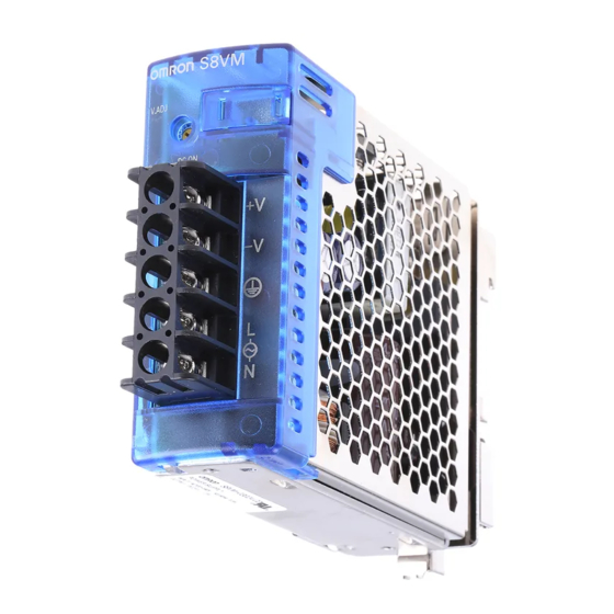
- Page 3 The S8VM series is unique in offering an undervoltage alarm means of 2 LEDs (yellow and red) on the front of the housing. with a diagnostic function to aid on-site troubleshooting.
- Page 4 S8VM series is available in a broad range of DC output international safety standards. And reflecting Omron’s ongoing voltages from 5 V up to 24 V and in powers from 15 W to 150 W. commitment to environmental protection, the series already...
-
Page 5: Switch Mode Power Supply
15: 15 V 24: 24 V Note: 1. The front-mounting type cannot be used as a back-mounting type. For a back-mounting configuration, use a DIN Rail mounting bracket type. 2. The housing and terminal of the connector for the undervoltage alarm output are provided with the S8VM-05024A@/P@, S8VM- 10024A@/P@ and S8VM-15024A@/P@. -
Page 6: Ordering Information
Ordering Information Note: S8VM-@@@@@CD and S8VM-@@@@@PD models are standard inventory items, for other items please contact your OMRON representative or distributor. Configura- Power Input voltage Output voltage Output current Front-mounting DIN Rail mounting bracket tion ratings Standard type Undervoltage alarm type... -
Page 7: Specifications
530 g max. Note: 1. Do not use the Inverter output for the Power Supply. Inverters with an output frequency of 50/60 Hz are available, but the rise in the internal temperature of the Power Supply may result in ignition or burning. -
Page 8: Block Diagrams
DC OUTPUT filter −V AC (N) Inrush Smooth- Rectification Rectifier/smoothing Harmonic current circuit current protection suppression circuit Drive control circuit Voltage Overcurrent detection circuit detection circuit Overvoltage detection circuit Photocoupler Switch Mode Power Supply S8VM S8VM Switch Mode Power Supply... - Page 9 DC LOW2 AC (N) Smooth- Common Common Photocoupler Photocoupler DC OUTPUT Drive −V Rectifier/smoothing circuit Remote sensing −S Drive control circuit Voltage Overcurrent detection circuit detection circuit Overvoltage detection circuit Photocoupler Switch Mode Power Supply S8VM S8VM Switch Mode Power Supply...
- Page 10 Correct the voltage drop in the load lines. Short bars (See note 5.) Note: 1. The fuse is located on the (L) side. It is NOT user-replace- able. 2. Protective earthing connection is the panel mounting hole shown in the figure below.
-
Page 11: Engineering Data
50 mm spacing on the right and left sides. If only 20 mm spacing is allowed, use the Power Supply at a load ratio of 80% or less. 4. When using 150-W models for a long period of time at an input voltage of 90 VAC or lower, reduce the load to 80% or less of the above derating curves. - Page 12 3. Use when the voltage drop is 0.3 V or lower. 4. When the +S and − S terminals are opened with the short bar removed, the overvoltage protection function is activated and the output voltage will be cut off.
- Page 13 24.0 V). During detection, the transistor is OFF (with no continuity across 8 and 10) and the LED (6: Yellow) lights. (The Undervoltage Alarm Function 1 is used as a latch holding function.) •...
- Page 14 Contact your OMRON representative if the Power Supply does not function normally after checking. The symbols in the table are as follows: : Lit, : Not lit, : Flashing Note: Flashing: The output voltage is unstable, causing the LED to repeatedly turn ON and OFF. DC ON DC LOW1 DC LOW2 Transistor...
- Page 15 The output voltage has returned to normal volt- Turn OFF the input power, and wait at least 60 s before turning ON the input power again to clear the age following a rapid drop caused by using the indicator status.
-
Page 16: Mounting Holes
Dimensions Note: All units are in millimeters unless otherwise indicated. � Front-mounting Models S8VM-015@@ 17.6 max. 80.5 S8VM-015@@C S8VM-01524A 81.5 68±0.5 8.5±0.5 Mounting Holes 62±0.5 Two, M3 (depth: 8 max.) 8.5±0.5 Surface Screw Mounting Side Two, 4 dia. 15.5±0.5 Mounting Two, M3 (depth: 8 max.) - Page 17 Two, M3 (depth: 8 max.) Two, 4 dia. 8.5±0.5 Mounting 23.5±0.3 15±0.2 68±0.5 Three, M3 (depth: 4 max.) 8±0.2 83±0.5 32.5±0.5 Note: The image is the S8VM-05024 Model. 13.6 max. 97±0.5 124.5 33.5 Bottom Three, 4 dia. Mounting 15±0.2 68±0.5 84.5 83±0.5...
- Page 18 8.5±0.5 Surface Screw Mounting Side 26.5±0.2 Two, 4 dia. 15±0.2 Mounting 7.5±0.2 Three, M3 (depth: 4 max.) 120±0.5 25±0.5 Note: The image is the S8VM-15024 Model. 68±0.5 135±0.5 Bottom Three, 4 dia. Mounting 15±0.2 13.6 max. 120±0.5 164.5 7.5±0.2 84.5 68±0.5...
- Page 19 S8VM-015@@D 17.6 max. 80.5 3.5 max. S8VM-015@@CD S8VM-01524AD 81.5 90.4 5.4 (Sliding: 9 max.) Note: The image is the S8VM-01524D Model. 15 max. 84.5 3.5 max. 35.1 84.5 46.2 94.4 5.4 (Sliding: 9 max.) Note: The image is the S8VM-01524AD Model.
- Page 20 17.6 max. 120.5 3.5 max. S8VM-050@@CD S8VM-05024AD S8VM-05024PD 82.5 130.4 5.4 (Sliding: 9 max.) Note: The image is the S8VM-05024D Model. 15 max. 124.5 3.5 max. 35.1 84.5 46.2 134.4 5.4 (Sliding: 9 max.) Note: The image is the S8VM-05024AD Model.
- Page 21 39.1 3.5 max. 160.5 S8VM-150@@CD S8VM-15024AD S8VM-15024PD 82.5 170.4 5.4 (Sliding: 9 max.) Note: The image is the S8VM-15024D Model. 15 max. 3.5 max. 45.6 164.5 84.5 46.2 174.4 5.4 (Sliding: 9 max.) Note: The image is the S8VM-15024AD Model.
- Page 22 � DIN Rail (Order Separately) Note: All units are in millimeters unless otherwise indicated. Mounting Rail (Material: Aluminum) PFP-100N PFP-50N 7.3 ± 0.15 35 ± 27 ± 0.15 15(5) * 1,000 (500) * *Values in parentheses are for the PFP-50N.
-
Page 23: Safety Precautions
As a reference value, the Product or touch the interior of the Product. allow at least 50 mm spacing on the right and left sides. If only 20 mm spacing is allowed, use the Power Supply at a load ratio of 80% Minor burns may occasionally occur. -
Page 24: Installation Environment
Here, Arrhenius Law applies, i.e., the life will capacity or output current does not exceed the rated output capacity be halved for each rise of 10° C or the life will be doubled for each or rated output current. -
Page 25: Series Operation
−V AC (N) AC (N) Turn the input power OFF once, and leave it OFF for at least 3 min- utes. Then turn it ON again to see if this clears the condition. Output Voltage (±) Check whether the +S terminal or − S terminal is opened with the short bar removed. -
Page 26: Typical Values
Note: 1. Refer to the Engineering Data section on page 7 to 8 for details. 2. The typical values indicate the values for an input condition of 230 VAC. All items are measured at a frequency of 50 Hz. Switch Mode Power Supply S8VM... -
Page 27: Warranty
CONTRACT, WARRANTY, NEGLIGENCE, OR STRICT LIABILITY. In no event shall the responsibility of OMRON for any act exceed the individual price of the product on which liability is asserted. IN NO EVENT SHALL OMRON BE RESPONSIBLE FOR WARRANTY, REPAIR, OR OTHER CLAIMS REGARDING THE... - Page 28 OMRON EUROPE B.V. Wegalaan 67-69, NL-2132 JD, Hoofddorp, The Netherlands. Tel: +31 (0) 23 568 13 00 Fax: +31 (0) 23 568 13 88 www.omron-industrial.com Austria France Netherlands Spain Tel: +43 (0) 1 80 19 00 Tel: +33 (0) 1 56 63 70 00...
Need help?
Do you have a question about the S8VM Series and is the answer not in the manual?
Questions and answers