Table of Contents
Advertisement
Quick Links
New Product
Switch Mode Power Supply
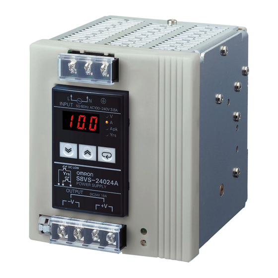
S8VS
60/90/120/180/240/480-W Models
New Models with Indication
Monitor and Simple Functions
for Easy System
Commissioning
• New 90-W models with indication monitor that
conform to UL Class 2 Output standards.
• New models with screwless terminal blocks
and indication monitor.
• Status displayed on 3-digit, 7-segment display.
• Safety standards:
UL508/60950-1,
CSA C22.2 No. 14/60950-1
(15-W and 30-W models),
CSA C22.2 No. 107.1/60950-1
(60-W to 240-W and 480-W models),
EN 50178 (= VDE0160)
• Input conditions: DC input is also possible from 80 to 370 VDC (BE models only, not compliant with EC Directives
and other safety standards).
15/30-W Models
Compact, Thin Power Supplies
That Mount Just About Anywhere
to Contribute to Control Panel
Downsizing
• Compact and thin: 22.5 × 85 × 96.5 mm (W × H × D).
• Three mounting directions
(standard, horizontal, facing horizontal).
• Mounting directly to the panel is possible.
• Safety standards:
UL508/60950-1/1604, cUL: CSA C22.2 No. 14/60950-1/213,
EN50178 (= VDE0160).
Features Common to All Models
• Mount to DIN Rail.
• Complies with SEMI F47-0706 (200-VAC input).
• RoHS-compliant.
(15/30/60/90/120/180/240/480-W Models)
Refer to Safety Precautions for All Power Supplies and Safety
!
Precautions on page 31.
1
Advertisement
Table of Contents

Related Manuals for Omron S8VS Series


Summary of Contents for Omron S8VS Series
- Page 1 New Product Switch Mode Power Supply S8VS (15/30/60/90/120/180/240/480-W Models) 60/90/120/180/240/480-W Models New Models with Indication Monitor and Simple Functions for Easy System Commissioning • New 90-W models with indication monitor that conform to UL Class 2 Output standards. • New models with screwless terminal blocks and indication monitor.
- Page 2 With indication monitor (total run time monitor) BE: With indication monitor but without alarm output (total run time monitor) Note: Estimates can be provided for coatings and other specifications that are not given in the datasheet. Ask your OMRON representative for details.
- Page 3 S8VS Ordering Information List of Models Note: For details on normal stock models, contact your nearest OMRON representative. Models without Indication Monitor (Standard Models) UL Class 2 Model number Model number Power ratings Input voltage Output voltage Output current Output standards...
- Page 4 S8VS Specifications Ratings/Characteristics Power ratings 15 W 30 W Item Type Standard Standard 5-V models 72% min. 70% min. Efficiency (typical) 12-V models 74% min. 76% min. (rated input voltage) 24-V models 77% min. 80% min. Voltage *1 100 to 240 VAC (allowable range: 85 to 264 VAC) Frequency *1 50/60 Hz (47 to 450 Hz) With 100-VAC input...
- Page 5 S8VS Power ratings 60 W 90 W Maintenance Total run time Maintenance forecast Item Type Standard Standard Total run time monitor forecast monitor monitor monitor Efficiency (typical) (rated input voltage) 78% min. 80% min. Voltage *1 100 to 240 VAC (allowable range 85 to 264 VAC *1) Frequency *1 50/60 Hz (47 to 450 Hz) With 100-VAC input 1.7 A max.
- Page 6 S8VS Power ratings 120 W 180 W Maintenance Total run time Maintenance Total run time Item Type Standard Standard forecast monitor monitor forecast monitor monitor Efficiency (typical) (rated input voltage) 80% min. Voltage *1 100 to 240 VAC (allowable range 85 to 264 VAC *1) Frequency *1 50/60 Hz (47 to 63 Hz) With 100-VAC input...
- Page 7 S8VS Power ratings 240 W 480 W Maintenance Total run time Maintenance Total run time Item Type Standard Standard forecast monitor monitor forecast monitor monitor Efficiency (typical) (rated input voltage) 80% min. 83% min. Voltage *1 100 to 240 VAC (allowable range 85 to 264 VAC) Frequency *1 50/60 Hz (47 to 63 Hz) With 100-VAC input...
- Page 8 S8VS Connections Block Diagrams S8VS-015@@ (15 W) Undervolt Fuse 2.5 A indicator AC (L) INPUT Noise filter DC OUTPUT −V AC (N) Inrush current Rectifier/ Overvoltage Rectifier/ protection smoothing protection smoothing circuit circuit circuit Drive control circuit Voltage Overcurrent detection circuit detection circuit Photocoupler S8VS-030@@ (30 W)
- Page 9 S8VS S8VS-06024-@ (60 W) Fuse 6.3 A AC (L) INPUT Noise filter DC OUTPUT −V AC (N) Rectifier Inrush current Smooth- Rectifier/smoothing circuit protection circuit circuit Drive control Overcurrent Current detection circuit circuit circuit Voltage detection circuit Overvoltage detection circuit Photocoupler S8VS-09024A@ (90 W) S8VS-09024B@ (90 W)
- Page 10 S8VS S8VS-09024-@ (90 W) S8VS-09024S-@ (90 W) Fuse 8.0 A AC (L) INPUT Noise filter DC OUTPUT −V AC (N) Inrush current Smooth Rectifier/smoothing circuit Rectifier protection circuit circuit Drive control circuit Overcurrent Current detection circuit circuit Voltage detection circuit Overvoltage detection circuit Photocoupler...
- Page 11 S8VS S8VS-12024-@ (120 W) Fuse 5.0 A AC (L) INPUT DC OUTPUT Noise filter −V AC (N) Inrush current Harmonic Smooth Rectifier/smoothing circuit Rectifier protection current circuit suppression circuit Drive control circuit Voltage detection circuit Overcurrent detection circuit Overvoltage detection circuit Photocoupler S8VS-18024A@ (180 W) Sinking type (S8VS-18024A, S8VS-18024B)
- Page 12 S8VS S8VS-18024-@ (180 W) Fuse 6.3 A AC (L) INPUT DC OUTPUT Noise filter −V AC (N) Inrush current Harmonic Rectifier/smoothing circuit Smooth Rectifier protection current circuit suppression circuit Drive control circuit Overcurrent Voltage detection circuit detection circuit Overvoltage detection circuit Photocoupler S8VS-24024A@ (240 W) S8VS-24024B@ (240 W)
- Page 13 S8VS S8VS-24024-@ (240 W) Fuse 8.0 A AC (L) INPUT DC OUTPUT Noise filter −V AC (N) Inrush current Harmonic Smooth Rectifier/smoothing circuit Rectifier protection current circuit suppression circuit Drive control circuit Overcurrent Voltage detection circuit detection circuit Overvoltage detection circuit Photocoupler S8VS-48024-@ (480 W) S8VS-48024A-@ (480 W)
-
Page 14: Derating Curve
S8VS Construction and Nomenclature (15-W, 30-W Models) Nomenclature 15-W, 30-W Models S8VS-015@@/S8VS-030@@ Name Function Connect the input lines to these terminals. *1 AC Input terminals (L), (N) Connect the ground line to this terminal. *2 Protective Earth terminal (PE) DC Output terminals (−V), (+V) Connect the load lines to these terminals. -
Page 15: Overvoltage Protection
S8VS Mounting Overvoltage Protection Consider the possibility of an overvoltage and design the system so Face-up mounting with DIN rail Standard mounting with DIN rail that the load will not be subjected to an excessive voltage even if the feedback circuit in the Power Supply fails. This power supply automatically protects itself and the load from overvoltage. - Page 16 S8VS Construction and Nomenclature (60-W, 90-W, 120-W, 180-W, 240-W, and 480-W Models) Nomenclature 60-W Models Name Function 1 AC Input terminals Connect the input lines to these Standard Model Models with Indication Monitor terminals. *1 (L), (N) S8VS-06024 S8VS-06024@ Protective Earth Connect the ground line to this terminal.
- Page 17 S8VS 480-W Models Name Function AC Input terminals Connect the input lines to these Standard Model terminals. *1 (L), (N) S8VS-48024 Protective Earth Connect the ground line to this terminal. *2 terminal (PE) DC Output terminals Connect the load lines to these (−V), (+V) terminals.
-
Page 18: Operation Mode
S8VS Mode Change (S8VS-@@@24A@@/S8VS-@@@24B@@/S8VS-@@@24BE@ Only) S8VS-@@@24A@@ models (with display monitor) can display the output voltage, output current, peak hold current, or maintenance forecast monitor time. S8VS-@@@24B@@/S8VS-@@@24BE@ models (with display monitor) can display the output voltage, output current, peak hold current, or total run time. Power-ON Model indication Operation mode... -
Page 19: Multiple Alarms
S8VS Peak Hold Current Reset Multiple Alarms The peak value of the output current (i.e., the peak hold current) can When two or more different alarms occur at the same time be reset on the display. Operation Mode Operation mode Key Press 3 seconds or more. -
Page 20: Self-Diagnostics Function
S8VS Self-Diagnostics Function Numbers in the following table indicate the number used in Nomenclature on pages 14 and 17. Setting after (6) Main display Description Output status Restoration method restoration Noise detected in voltage or No change Automatic reset. No change current Maintenance forecast output... - Page 21 S8VS Maintenance Forecast (S8VS-@@@24A@@) Indication and Output When the Product is purchased, “ ” will be indicated. As Displays when the maintenance forecast has reached the set value. electrolytic capacitors deteriorate, indication changes to “ ” (Refer to page 22). “ ”...
- Page 22 S8VS Maintenance Forecast Monitor Function The Power Supply is equipped with electrolytic capacitors. The maintenance forecast monitor function shows an approximate The electrolyte inside the electrolytic capacitor penetrates the sealing period left for maintenance of the Power Supply due to deterioration rubber and evaporates as time passes since it is manufactured, which of electrolytic capacitors.
-
Page 23: Time Chart
S8VS Models with Total Run Time Monitor Time Chart (S8VS-@@@24B@@/S8VS-@@@24BE@) Total run time S8VS-06024B 50 kh The accumulated value of the operating time of the Power Supply is displayed as the total run time. (kh) will be displayed initially after purchase and then the display will advance in 1-kh steps as the operating time accumulates. - Page 24 S8VS Engineering Data (60-W, 90-W, 120-W, 180-W, 240-W, and 480-W Models) Derating Curve Power Supply is used for applications with frequent inrush current or overloading at the load end. Do not use the Power Supply for such applications. Peak Output Current (S8VS-48024@ only) See note 1.
- Page 25 S8VS Undervoltage Alarm Function (Indication and Output) (S8VS-@@@24A@@/S8VS-@@@24B@@/ S8VS-@@@24BE@ Only) When output voltage drop is detected, an alarm ( ) and lowest output voltage value are indicated alternately. The preset value of detection voltage can be changed in the setting mode. (From 18.5 to 27.5 V in 0.1-V steps.
- Page 26 S8VS Dimensions Power Supplies with Screw Terminal Blocks Note: All units are in millimeters unless otherwise indicated. S8VS-015@@ (15 W) S8VS-030@@ (30 W) Five, M3.5 terminal screws 4.8 with square washers (Sliding: 10 max.) 35.2 22.5 96.4 (Sliding: 10 max.) Rail stopper Note: The illustration is the S8VS-03024 model.
- Page 27 S8VS S8VS-24024 (240 W) Seven, M4 terminal screws S8VS-24024A@ (240 W) with square washers 125.3 S8VS-24024B@ (240 W) 120.3 S8VS-24024BE (240 W) 35.4 4.5 (Sliding: 15 max.) Rail stopper Rail stopper Screwless block (2.5-mm pitches) Note: The illustration shows the S8VS-24024A model. S8VS-48024 (480 W) 127.2 Nine, M4 terminal screws with square washers...
- Page 28 S8VS S8VS-18024-F (180 W) S8VS-18024A@-F (180 W) 116.3 S8VS-18024B@-F (180 W) S8VS-18024BE-F (180 W) 35.4 97.3 4.5 (Sliding: 15 max.) Rail stopper Note: The illustration shows the S8VS-18024-F model. S8VS-24024-F (240 W) S8VS-24024A@-F (240 W) 117.6 S8VS-24024B@-F (240 W) S8VS-24024BE-F (240 W) 35.4 97.3 4.5 (Sliding: 15 max.)
-
Page 29: End Plate
S8VS DIN Rail (Order Separately) Note: All units are in millimeters unless otherwise indicated. Mounting Rail (Material: Aluminum) PFP-100N PFP-50N 7.3 ± 0.15 35 ± 27 ± 0.15 15(5) * 1,000 (500) * * Values in parentheses are for the PFP-50N. Mounting Rail (Material: Aluminum) PFP-100N2 35 ±... -
Page 30: Mounting Brackets
S8VS Mounting Brackets Name Model Side-mounting Bracket (for 15- and 30-W models) S82Y-VS30P Side-mounting Bracket (for 60-, 90-, and 120-W models) S82Y-VS10S Side-mounting Bracket (for 180-W models) S82Y-VS15S Side-mounting Bracket (for 240-W models) S82Y-VS20S Front-mounting Bracket (for 60-, 90-, 120-, 180-, and 240-W models) * S82Y-VS10F Note: Brackets cannot be used for 480-W models. -
Page 31: Safety Precautions
S8VS Safety Precautions !CAUTION Minor electric shock, fire, or Product failure may Wiring occasionally occur. Do not disassemble, modify, or • Connect the ground completely. A protective earthing terminal repair the Product or touch the interior of the stipulated in safety standards is used. Electric shock or malfunction Product. - Page 32 S8VS • Strip I/O wires for 11 mm when using a screwless terminal block. * The rated current for output terminals is 10 A per terminal. Be sure 60-, 90-, 120-, to use multiple terminals simultaneously for current that exceeds 180-, 240-W the terminal rating.
-
Page 33: Parallel Operation
S8VS Output Voltage Adjuster (V.ADJ) Parallel Operation • The output voltage adjuster (V.ADJ) may possibly be damaged if it The Product is not designed for parallel operation. is turned with unnecessary force. Do not turn the adjuster with Incorrect excessive force. AC (L) •... - Page 34 MEMO...
-
Page 35: Warranty
CONTRACT, WARRANTY, NEGLIGENCE, OR STRICT LIABILITY. In no event shall the responsibility of OMRON for any act exceed the individual price of the product on which liability is asserted. IN NO EVENT SHALL OMRON BE RESPONSIBLE FOR WARRANTY, REPAIR, OR OTHER CLAIMS REGARDING THE... - Page 36 The Netherlands IL 60173-5302 U.S.A. Tel: (31)2356-81-300/Fax: (31)2356-81-388 Tel: (1) 847-843-7900/Fax: (1) 847-843-7787 © OMRON Corporation 2002 All Rights Reserved. OMRON (CHINA) CO., LTD. OMRON ASIA PACIFIC PTE. LTD. In the interest of product improvement, Room 2211, Bank of China Tower, No.
Need help?
Do you have a question about the S8VS Series and is the answer not in the manual?
Questions and answers