Advertisement
New Product
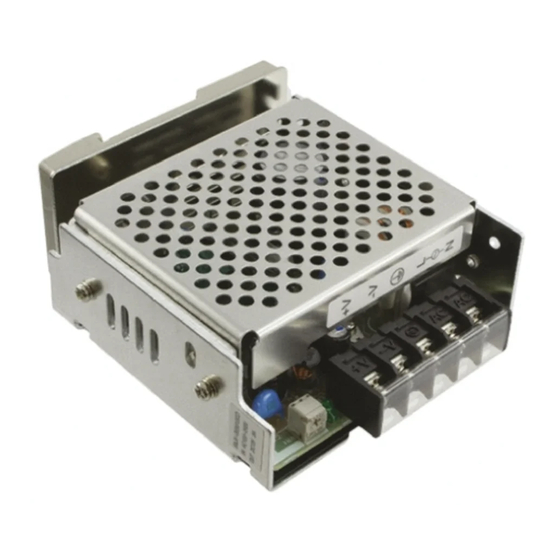
Switch Mode Power Supply
(15/35/50/100/150/300/600-W Models)
S8JX
Low-profile Power Supply to Help
Reduce Panel Depth
• Easy Mounting:
Mounting Bracket provided as a standard feature.
(except for DIN Rail-mounting models)
Mounts to DIN Rail. (except 600-W model)
Screw-mount at the top. (except 300-/600-W models)
• Safety standards:
UL 508/60950-1
cUL CSA C22.2 No. 107.1
cUR CSA C22.2 No. 60950-1
EN 50178 (= VDE 0160)
EN 60950-1 (= VDE 0805 Teil 1)
• EMC: Conforms to EN 61204-3 Class A.
(
EMI: EN55011
EMS: EN61000-4
Note: Refer to Safety Precautions on page 17.
Model Number Structure
Model Number Legend
Note: Not all combinations are possible. Refer to List of Models in Ordering Information on page 2.
15-/35-/50-/100-/150-W Models
S8JX-G@@@@@@@
1
2
3 4
1. Power Ratings
015: 15 W
035: 35 W
050: 50 W
100: 100 W
150: 150 W
2. Output Voltage
05: 5 V
12: 12 V
15: 15 V
24: 24 V
300-/600-W Models
S8JX-G@@@@@@
1
2
3
1. Power Ratings
300: 300 W
600: 600 W
2. Output Voltage
24: 24 V
3. Configuration/mounting (covered type)
C: Front-mounting
CD: DIN Rail-mounting
)
3. Configuration (15/35/50/100/150 W model)
None: Open-frame
C: Covered
4. Configuration/mounting
None: Front-mounting
D: DIN Rail-mounting
1
Advertisement
Table of Contents

Related Manuals for Omron S8JX


Summary of Contents for Omron S8JX
- Page 1 EMS: EN61000-4 Note: Refer to Safety Precautions on page 17. Model Number Structure Model Number Legend Note: Not all combinations are possible. Refer to List of Models in Ordering Information on page 2. 15-/35-/50-/100-/150-W Models S8JX-G@@@@@@@ 1. Power Ratings 3. Configuration (15/35/50/100/150 W model)
-
Page 2: Ordering Information
S8JX Ordering Information List of Models Note: For details on normal stock models, contact your nearest OMRON representative. Configuration Input voltage Power ratings Output voltage (VDC) Output current Model 5 VDC S8JX-G01505 12 V 1.3 A S8JX-G01512 15 W 15 V... - Page 3 Refer to Overload Protection on page 11. *2. Do not use an Inverter output for the Power Supply. Inverters with an output frequency of 50/60 Hz are available, but the rise in the internal temperature of the Power Supply may result in ignition or burning.
- Page 4 Refer to Overload Protection on page 11. *2. Do not use an Inverter output for the Power Supply. Inverters with an output frequency of 50/60 Hz are available, but the rise in the internal temperature of the Power Supply may result in ignition or burning.
- Page 5 Refer to Overload Protection on page 11. *2. Do not use an Inverter output for the Power Supply. Inverters with an output frequency of 50/60 Hz are available, but the rise in the internal temperature of the Power Supply may result in ignition or burning.
-
Page 6: Block Diagrams
S8JX Connections Block Diagrams S8JX-G015@@@@ (15 W) AC (L) Fuse Noise INPUT 2.0 A DC OUTPUT filter −V AC (N) Rectifier/ Inrush current Rectifier Smoothing protection circuit Smoothing circuit Drive control Circuit Overcurrent Voltage detection detection circuit Overvoltage detection circuit... - Page 7 Overvoltage detection circuit Photocoupler Parallel operation selector Note: Short-circuit the input voltage selector terminals if the input is 100 to 120 VAC. Keep the terminals open if the input is 200 to 240 VAC. S8JX-G60024@@ (600 W) Rectifier/ Smoothing circuit...
- Page 8 Protective Earthing Terminal ( Input Voltage Selector Terminals Short-circuit the terminals if the input is 100 to 120 VAC and open the terminals if the input is 200 to 230 VAC. Output Indicator (DC ON: Green) Lights while a Direct Current (DC) output is ON.
-
Page 9: Engineering Data
Ambient Temperature (°C) Ambient Temperature (°C) Note: 1. Internal parts may occasionally deteriorate or be damaged. Do not use the Power Supply in areas outside the derating curve (i.e., the area shown by shading A in the above graph). 2. If there is a derating problem, use forced air-cooling. - Page 10 2. When mounting the Power Supply, mounting it to a metal plate (*) is recommended. 3. Install the Power Supply so that the air flow circulates around the Power Supply, as the Power Supply is designed to radiate heat by means of natural air flow.
-
Page 11: Overload Protection
Reset the input power by turning it OFF for at least three minutes and then turning it back ON again. - Page 12 ±1 35.5 Mounting ±0.5 ±1 39.5 ±0.5 ±0.5 3.5 dia. 26.5 17.5 Two, M3 (Depth 4 mm max.) ±0.5 S8JX-G050@@ (50 W) S8JX-G050@@C (50 W) 5 max. Panel mounting holes dimensions ±1 10 max. Label Surface screw mounting Two, M3 Side ±0.5...
- Page 13 S8JX S8JX-G30024C (300 W) Eight, M4 holes (depth: 8 max. on both sides) 20 max. Panel mounting holes dimensions 4 max. 167.1 Nine, M4 terminal screws ±1 Surface screw mounting Four, 4.5 dia. Side ±1 ±0.5 ±0.5 Mounting ±0.5 Four, 4.5 dia.
- Page 14 Dimensions dimensions bracket as shown in the illustration on the right, hook the holes (parts a) in the Power Supply on 4.6 15 ±0.2 hooks on the mounting bracket (parts b), and secure the Power Supply with two mounting Two, M3 screws.
- Page 15 6 max. S8JX-G015@@CD (15 W) Label S8JX-G035@@ (35 W) 5 max. S8JX-G035@@CD (35 W) ±1 Five, M3.5 Cover 98.6 7 (Sliding: 16.6 max.) S8JX-G050@@D (50 W) 14.5 max. ±1 10 max. ±1 6 max. S8JX-G050@@CD (50 W) Label 5 max.
-
Page 16: End Plate
M4 spring washer Note: 1. If there is a possibility that the Unit will be subject to vibration or shock, use a steel DIN Rail. Otherwise, metallic filings may result from aluminum abrasion. 2. If the Unit may be subjected to sliding to either side, attach an End Plate (model PFP-M) on each side of the Unit. -
Page 17: Safety Precautions
• When mounting two or more Power Supplies side-by-side, allow at least 20 mm spacing between them. • Provide a space of at least 20 mm back and forth when mounting 300-W and 600-W models as well. *1. Convection of air •... -
Page 18: Series Operation
Power Supply. • It is desirable to set the same value on the voltage adjuster of each Power Supply. -
Page 19: Fan Replacement
• Checking overvoltage or internal protection: Turn the power supply OFF once, and leave it OFF for at least 7 minutes. Then turn it ON again to see if this clears the condition. Switching the AC Input Voltage between 100 and 200 VAC... - Page 20 Note: 1. Refer to the Engineering Data on pages 9 to 11 for details. 2. The typical values indicate the values for an input condition of 230 VAC. All items are measured at a frequency of 50 Hz. ALL DIMENSIONS SHOWN ARE IN MILLIMETERS.
- Page 21 MEMO...
- Page 22 MEMO...
-
Page 23: Warranty
CONTRACT, WARRANTY, NEGLIGENCE, OR STRICT LIABILITY. In no event shall the responsibility of OMRON for any act exceed the individual price of the product on which liability is asserted. IN NO EVENT SHALL OMRON BE RESPONSIBLE FOR WARRANTY, REPAIR, OR OTHER CLAIMS REGARDING THE... - Page 24 Industrial Component Division 2-2-1 Nishikusatsu, Kusatsu-shi, Shiga, 525-0035 Japan OMRON ASIA PACIFIC PTE. LTD. Tel: (81) 77-565-5160/Fax: (81) 77-565-5569 No. 438A Alexandra Road # 05-05/08 (Lobby 2), Alexandra Technopark, Singapore 119967 Tel: (65) 6835-3011/Fax: (65) 6835-2711 Regional Headquarters OMRON (CHINA) CO., LTD.
Need help?
Do you have a question about the S8JX and is the answer not in the manual?
Questions and answers