
Related Manuals for Omron S8VK-X


Summary of Contents for Omron S8VK-X
- Page 1 Product Overview IP Address Setting and Resetting Monitoring and Switch-mode Power Supplies Setting with the EtherNet/IP Monitoring and Communications Manual Setting with the Modbus TCP S8VK-X T213-E1-01...
- Page 2 No patent liability is assumed with respect to the use of the information contained herein. Moreover, because OMRON is constantly striving to improve its high-quality products, the information contained in this manual is subject to change without notice. Every precaution has been taken in the preparation of this manual. Neverthe- less, OMRON assumes no responsibility for errors or omissions.
-
Page 3: Preface
PDF version of this manual can be downloaded from the OMRON website. (http://www.omron.co.jp) For details on how to use functions other than the S8VK-X communications function, refer to the data sheet of the S8VK-X and the instruction manual (attached to the product). -
Page 4: Terms And Conditions Agreement
Omron’s exclusive warranty is that the Products will be free from defects in materials and workman- ship for a period of twelve months from the date of sale by Omron (or such other period expressed in writing by Omron). Omron disclaims all other warranties, express or implied. -
Page 5: Application Considerations
Disclaimers Performance Data Data presented in Omron Company websites, catalogs and other materials is provided as a guide for the user in determining suitability and does not constitute a warranty. It may represent the result of Omron’s test conditions, and the user must correlate it to actual application requirements. Actual perfor- mance is subject to the Omron’s Warranty and Limitations of Liability. -
Page 6: Precautions For Correct Use
Precautions for Correct Use Precautions for Correct Use Be sure to observe the following precautions. Communications • Communications setup is necessary for installation and replacement. Make communication set- tings according to this manual. • Follow the instructions in this manual for connection method and cables to be used with the Ether- Net/IP or the Modbus TCP. -
Page 7: Revision History
Revision History Revision History A manual revision code appears as a suffix to the catalog number on the front cover of the manual. T213-E1-01 Revision code Revision code Date Revised content December 2017 Original production Switch-mode Power Supplies Communications Manual (T213) - Page 8 Revision History Switch-mode Power Supplies Communications Manual (T213)
-
Page 9: Sections In This Manual
Sections in this Manual Sections in this Manual Product Overview IP Address Setting and Resetting Monitoring and Setting with the EtherNet/IP Monitoring and Setting with the Modbus TCP Switch-mode Power Supplies Communications Manual (T213) -
Page 10: Table Of Contents
3-2-1 Connection setting ........................3-6 3-2-2 Data to be Tag Data Link Target in the S8VK-X ................3-6 List of Monitoring and Setting Contents Using the CIP Message Communications ..3-8 3-3-1 Services Supported by Objects in the S8VK-X ................3-8 3-3-2 Monitor Object of the S8VK-X (Class ID: 372 hex) .............. - Page 11 CONTENTS Section 4 Monitoring and Setting with the Modbus TCP Overview..........................4-2 Function Codes ........................4-3 4-2-1 Function Code List........................4-3 4-2-2 03 hex: Reading of multiple registers ..................4-3 4-2-3 06 hex: Operation command (Resets the peak hold current) ............. 4-5 4-2-4 10 hex: Writing of multiple registers....................
- Page 12 CONTENTS Switch-mode Power Supplies Communications Manual (T213)
- Page 13 Product Overview This section describes the overview of the S8VK-X. 1-1 List of Models ..........1-2 1-2 Nomenclature and Functions .
-
Page 14: List Of Models
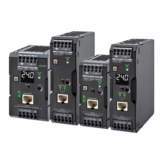
1 Product Overview List of Models This section shows the model list of the S8VK-X. The S8VK-X has a type with display monitor and a type without display monitor. With Indication Monitor Power Rated output Rated output Maximum Rated input voltage... -
Page 15: Nomenclature And Functions
1 Product Overview Nomenclature and Functions This section describes the nomenclature and functions of the S8VK-X. In the following, the position of each part is indicated by number, and its contents are shown in a list. With Indication Monitor ... - Page 16 1 Product Overview Terminal Name Function name (15) Operation indicator Lights up when the output voltage is indicated. (white) Lights up during indication of output current. Lights up during indication of peak hold current. Lights up during replacement time calculation year indication.
-
Page 17: Communications Specifications
1 Product Overview Communications Specifications This section shows the communications specifications of the S8VK-X. Item Specification Communications protocol EtherNet/IP, Modbus TCP Physical layer 100 BASE-TX Media access method CSMA/CD Modulation system Baseband Topology Star configuration Transmission speed 100 Mbps Twisted pair cable (with shield: STP): Category 5,... -
Page 18: Communications Methods And Types Of Data To Be Communicated
This section shows the communications methods of the S8VK-X and the types of data to be communi- cated. You can read or write the communications target data of the S8VK-X using one of the following meth- ods. For details on the communications methods and target data, refer to the sections shown in the table below. -
Page 19: Measurement And Calculation Data
Read Read Read *1. Peak hold current measured can be reset. It can be reset by operating the "Peak hold current reset" bit. *2. It can be checked with "S8VK-X status". 1 - 7 Switch-mode Power Supplies Communications Manual (T213) -
Page 20: Self-Diagnosis Information
1 Product Overview Self-Diagnosis Information This section shows status information that can be confirmed by the self-diagnosis of the S8VK-X. The following self-diagnosis status can be checked with the "S8VK-X status" using the EtherNet/IP or the Modbus TCP. EtherNet/IP Restoration... -
Page 21: Product Information And Communications Setting Data
Setting Data This section shows product information and communications setting data that can be read or written using communications with the S8VK-X. The following product information and communications setting data can be read or written using the EtherNet/IP or the Modbus TCP. -
Page 22: Communications Wiring
This section describes the communications wiring of the S8VK-X. Connect the S8VK-X with the host devices such as PLC or PC via the industrial switching hub with the Ethernet cables. For the communications cables and industrial switching hubs, use the recommended items shown on the next page. - Page 23 1 Product Overview Recommended EtherNet/IP Communication Cables (Order Sepa- rately) Use an STP cable (shielded twisted pair cable) of Category 5 or above. Part name Manufacturer Model number Contact Information Cable Hitachi Metals, Ltd. NETSTAR-C5E SA Kanetsu Co., Ltd., Planning Department TEL: +81 (0)75-662-0996 0.5×4P RJ45 connector...
-
Page 24: Procedure
Net/IP 3. Monitoring ↓ from the host The host (PLC, PC, etc.) reads the state of the S8VK-X using EtherNet/IP (tag data link or CIP message commu- Section 4 Monitoring and nications) or Modbus TCP. Setting with the Modbus ↓... -
Page 25: Ip Address Setting And Resetting
IP Address Setting and Resetting This section describes the setting and resetting of the IP address of the S8VK-X. 2-1 IP Address Settings ..........2-2 2-2 Communications Reset Function . -
Page 26: Ip Address Settings
Setting the IP Address of the S8VK-X from the Network Configurator Start the Network Configurator. Select the [Network Configurator] from the [Start] - [All Programs] - [OMRON] - [Sysmac Studio] - [Network Configurator for EtherNetIP] to start the Network Configurator. - Page 27 Set the IP address of the S8VK-X. Select the [Setup TCP/IP Configuration] from the [Tools] to open the [Setup TCP/IP Configura- tion] Dialog Box. Enter "192.168.250.20", which is the default IP address of the S8VK-X, in the [Target IP Address] Box. 2 - 3...
- Page 28 1. Enter the IP address, subnet mask, and default gateway. 2. Click the [Set to the Device] Button. 3. Click the [Reset the Device] Button to apply the IP address setting in the S8VK-X. Getting an IP Address from a BOOTP Server 1.
-
Page 29: Communications Reset Function
2 IP Address Setting and Resetting Communications Reset Function This section describes the communications reset function of the S8VK-X. This function temporarily resets the communications settings to their factory default values. Use this function when the IP address previously set is no longer known and communication is not possible. - Page 30 2 IP Address Setting and Resetting 2 - 6 Switch-mode Power Supplies Communications Manual (T213)
-
Page 31: Monitoring And Setting With The Ethernet/Ip
3-2-2 Data to be Tag Data Link Target in the S8VK-X ......3-6 3-3 List of Monitoring and Setting Contents Using the CIP Message Communications . -
Page 32: Overview
This section describes how to monitor the S8VK-X using the EtherNet/IP. 3-1-1 What is Monitoring Using EtherNet/IP? The S8VK-X can be monitored from host devices such as PC and PLC via EtherNet/IP. The following two communications methods can be used. Communications... -
Page 33: Tag Data Link
• Which memory area (I/O memory or variables) in the PLC should be used for the tag data link. • The size of the internal data (parameter) of the S8VK-X is 20 bytes for all models 2) -1 Drag a S8VK-X to the PLC and register it. - Page 34 Right-click on the target device list in the tool box on the EtherNet/IP connection settings Tab page and select the [Display EDS Library] menu. Click the [Install] Button and import the EDS file of each S8VK-X in the [EDS Library] Dialog Box.
-
Page 35: Cip Message Communications
3-1-3 CIP Message Communications Any CIP command can be issued to the S8VK-X on the EtherNet/IP network from CIP clients such as PC (supporting the EtherNet /IP) or NJ/NX-series Controller using the Explicit messages. This allows you to perform various processing such as data reading and writing of the S8VK-X. -
Page 36: List Of Monitoring Contents Using The Tag Data Link Communications
Identification Number and Size of Internal Data to be Tag Data Link The identification number (the instance ID of the Assembly object) and the size of internal data (Assem- bly object) to be tag data link target in the S8VK-X are as follows. Identification number (Instance... - Page 37 Data range Meaning of the value Size Address S8VK-X status 0000 to 000F hex 1 word Status of S8VK-X Output voltage mea- 0000 to 2706 hex 0.00 to 99.90 V 1 word sured (Decimal 0 to 9990) (0.10 V increments)
-
Page 38: List Of Monitoring And Setting Contents Using The Cip Message Communications
This section shows the contents of monitoring and setting using the CIP message communications and examples of communications instructions. 3-3-1 Services Supported by Objects in the S8VK-X The services supported by the objects in the S8VK-X are as follows. Object name Class ID Function... - Page 39 Default name bute type value 64 hex S8VK-X status 0000 to 000F hex Read UINT Status of S8VK-X 65 hex Output voltage 0000 to 2706 hex 0.00 to 99.90 V Read UINT measured (Decimal 0 to 9990) (0.10 V increments)
-
Page 40: Setting Object Of The S8Vk-X (Class Id: 373 Hex)
3 Monitoring and Setting with the EtherNet/IP 3-3-3 Setting Object of the S8VK-X (Class ID: 373 hex) Service Codes Supported services Service Service name Description Codes Classes Instances 10 hex Set_Attribute_Single Write the value of the specified attri- Not supported. -
Page 41: Identity Object (Class Id: 01 Hex)
3 Monitoring and Setting with the EtherNet/IP 3-3-4 Identity Object (Class ID: 01 hex) This object reads the identification information of the S8VK-X, reads the state of the built-in EtherNet/IP port. Service Codes Supported services Service Service name Description Codes... - Page 42 3 Monitoring and Setting with the EtherNet/IP Attribute Data Parameter name Description Attribute Data type Default value 06 hex Serial Number Serial number Read UDINT Product spe- cific 07 hex Product Name Product name Read SHORT_STRI Product spe- cific *1. Product Codes Model Product Codes S8VK-X09024A-EIP...
-
Page 43: Tcp/Ip Interface Object (Class Id: F5 Hex)
3 Monitoring and Setting with the EtherNet/IP 3-3-5 TCP/IP Interface Object (Class ID: F5 hex) This object is used to read and write settings such as the IP address, subnet mask, and default gate- way. Service Codes Supported services Service Service name Description Codes... - Page 44 3 Monitoring and Setting with the EtherNet/IP Data Attribute Parameter Attri- Description Data name bute Default value type 02 hex Configuration Indicates a Setup Read DWORD Bit 0: BOOTP Client: Always TRUE. Capability that can be set to Bit 1: DNS Client: Always FALSE. the built-in inter- Bit 2: DHCP Client: Always FALSE.
-
Page 45: Example Of The Cip Message Communications Instruction
3 Monitoring and Setting with the EtherNet/IP 3-3-6 Example of the CIP Message Communications Instruction The following shows an example of reading data in the S8VK-X from the NJ/NX-series Controller using the CIP message communications instruction. Example: Reading of output voltage measured Send the following CIP message. - Page 46 Class ID, Instance ID, Attribute ID Example) Deterioration degree (current value): Specify the following. • ClassID: = 372 hex (meaning "Monitor Object of the S8VK-X") • InstanceID: = 01 hex (fixed) • IsAttributeID: = TRUE (meaning to use an attri- bute ID) •...
- Page 47 Monitoring and Setting with the Modbus TCP This section describes how to monitor and configure the S8VK-X using the Modbus TCP. 4-1 Overview ........... . . 4-2 4-2 Function Codes .
-
Page 48: Overview
Note The socket is an interface for using TCP directly from the user program. The host device specifies the IP address of S8VK-X and TCP port number of 502 (01F6 hex) and opens the socket in Active. After that, it sends Modbus TCP request and reads and writes the internal data of the S8VK-X. -
Page 49: Function Codes
4 Monitoring and Setting with the Modbus TCP Function Codes This section describes function codes that can be used with Modbus TCP. 4-2-1 Function Code List The function codes that can be used are as follows. Function code Function name Usages 03 hex Reading of multiple registers... - Page 50 Information Request (6): Start address : Specify the address of the S8VK-X status. (7): Number of words to read : The total number of the measurement/calculation data and self-diag- nostic information is 10 words (20 bytes), so specify 000A hex ...
-
Page 51: Hex: Operation Command (Resets The Peak Hold Current)
4 Monitoring and Setting with the Modbus TCP 4-2-3 06 hex: Operation command (Resets the peak hold current) This function resets the peak hold current. Frame configurations The frame configurations of ModbusTCP are as follows. Request Bytes (1): Transaction ID : Specify any value. -
Page 52: 10 Hex: Writing Of Multiple Registers
4 Monitoring and Setting with the Modbus TCP 4-2-4 10 hex: Writing of multiple registers This function can write data to multiple registers with the specified address as the start address. Frame configurations The frame configurations of ModbusTCP are as follows. ... -
Page 53: Exception Code List
4 Monitoring and Setting with the Modbus TCP Example: Change IP Address Request → → (1): Transaction ID : Specify any value. For example, 0000 hex is used in this explanation. (2): Protocol ID : Specify 0000 hex. (3): Number of bytes transferred : The total number of bytes of (4) and the successor are 11, so specify 000B hex. -
Page 54: Register Address Lists
(Decimal 0 to 15768000) (1 hour increments) *1. R: Read using Reading of multiple registers (03 hex). W: Write using Writing of multiple registers (10 hex). *2. The contents of the S8VK-X status are as follows. Bit contents Bit position Status... -
Page 55: Product Information And Communications Setting Data
4 Monitoring and Setting with the Modbus TCP 4-3-2 Product Information and Communications Setting Data Number of Address Data name Data Range bytes 000A hex Vendor ID Always 002F hex. 000B hex Device type Always 0302 hex. 000C hex Product code 000D hex Device major revision 000E hex... - Page 56 4 Monitoring and Setting with the Modbus TCP 4 - 10 Switch-mode Power Supplies Communications Manual (T213)
- Page 58 The Netherlands Hoffman Estates, IL 60169 U.S.A. Tel: (31)2356-81-300/Fax: (31)2356-81-388 Tel: (1) 847-843-7900/Fax: (1) 847-843-7787 © OMRON Corporation 2017 All Rights Reserved. OMRON (CHINA) CO., LTD. OMRON ASIA PACIFIC PTE. LTD. In the interest of product improvement, Room 2211, Bank of China Tower, No.
Need help?
Do you have a question about the S8VK-X and is the answer not in the manual?
Questions and answers