Table of Contents
Advertisement
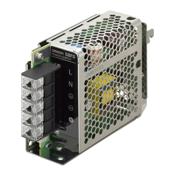
Switch Mode Power Supply
S8FS-G (15/30/50/100/150/300/600-W Models)
Superior Basic Performance That
Ensures Reliability. Wide Range
of Standards Certification and
Greater Usability.
• Superior basic performance that ensures reliability
Ambient temperatures up to 70°C, greater
resistance to rusting with aluminum/stainless steel
case, and applications at altitudes up to 3,000 m.
• Certification for Global Standards
North America: UL 508 (Listing)*, CSA C22.2
Europe: Overvoltage Category III (EN 50178)
EMI: Class B (EN 61204-3)
No need for control circuit transformers for which the
Machinery Directive is specified. (EN/IEC 61558-2-16)
* Refer to pages 4 to 10 for certified models.
• Greater Usability
The Terminal Block Cover prevents screws from
dropping out and the Front Cover prevents
ingress of foreign matter.
Lineup
Output voltage
5 V
12 V
15 V
24 V
48 V
Model Number Structure
Model Number Legend
Note: Not all combinations are possible. Refer to List of Models in Ordering Information, below.
S8FS- G@@@ @@ @ @-@ @ @
1
2
3
1. Power Ratings
2. Output voltage
015: 15 W
05: 5 V
030: 30 W
12: 12 V
050: 50 W *1
15: 15 V
100: 100 W *2
24: 24 V
150: 150 W *3
48: 48 V
300: 300 W
600: 600 W
*1. The output electric power is 40 W for products with an output voltage of 5 V.
*2. The output electric power is 80 W for products with an output voltage of 5 V.
*3. The output electric power is 105 W for products with an output voltage of 5 V.
15 W
30 W
Yes
Yes
Yes
Yes
Yes
Yes
Yes
Yes
---
---
4
5
6 7
3. Configuration
C:
With cover/Direct mounting
CD: With cover/DIN Rail mounting
4. Option (1)
None: Screw terminal block
Connectors *4
E:
Refer to Safety Precautions for All Power Supplies and Safety
!
Precautions on page 29.
Power rating
50 W
100 W
Yes
Yes
Yes
Yes
Yes
Yes
Yes
Yes
---
---
5. Option (2) *5
None: None
W:
Parallel operation
6. Option (3) *6
None: None
R:
Remote control
*4. Applicable only for 150 W or less and 24 V.
*5. Applicable only for 600 W and 24 V.
*6. Applicable only for 100 W or more and 24 V.
*7. Applicable only for 300 W or more and 24 V.
150 W
300 W
Yes
---
Yes
Yes
Yes
Yes
Yes
Yes
Yes
Yes
7. Option (4) *7
None: None
H:
Extended hold time
600 W
---
Yes
Yes
Yes
Yes
1
Advertisement
Table of Contents

Related Manuals for Omron S8FS-G Series


Summary of Contents for Omron S8FS-G Series
- Page 1 Switch Mode Power Supply S8FS-G (15/30/50/100/150/300/600-W Models) Superior Basic Performance That Ensures Reliability. Wide Range of Standards Certification and Greater Usability. • Superior basic performance that ensures reliability Ambient temperatures up to 70°C, greater resistance to rusting with aluminum/stainless steel case, and applications at altitudes up to 3,000 m.
-
Page 2: Ordering Information
S8FS-G Ordering Information List of Models Note: For details on normal stock models, contact your nearest OMRON representative. With Cover/DIN Rail Mounting Power ratings Input voltage Output voltage (VDC) Output current Built-in fan Model S8FS-G01505CD 12 V 1.3 A S8FS-G01512CD... - Page 3 13 A S8FS-G60048C Note: 1. Ask your OMRON representative for pricing information on optional models. 2. Front-mounting is not possible. To mount a Power Supply from the front, purchase a DIN Rail-mounting Power Supply and a Front-mounting Bracket (sold separately).
-
Page 4: Specifications
S8FS-G Specifications Power rating 15 W Item Output voltage 12 V 15 V 24 V 100 VAC input 80% typ. 84% typ. 84% typ. 85% typ. Efficiency * 200 VAC input 80% typ. 84% typ. 84% typ. 86% typ. 230 VAC input 80% typ. - Page 5 S8FS-G Power rating 30 W Item Output voltage 12 V 15 V 24 V 100 VAC input 81% typ. 84% typ. 86% typ. 86% typ. Efficiency * 200 VAC input 81% typ. 86% typ. 88% typ. 88% typ. 230 VAC input 81% typ.
- Page 6 S8FS-G Power rating 50 W Item Output voltage 12 V 15 V 24 V 100 VAC input 81% typ. 84% typ. 86% typ. 86% typ. Efficiency * 200 VAC input 82% typ. 86% typ. 88% typ. 89% typ. 230 VAC input 82% typ.
- Page 7 S8FS-G Power rating 100 W Item Output voltage 12 V 15 V 24 V 100 VAC input 79% typ. 84% typ. 85% typ. 87% typ. Efficiency * 200 VAC input 81% typ. 86% typ. 87% typ. 89% typ. 230 VAC input 81% typ.
- Page 8 S8FS-G Power rating 150 W Item Output voltage 12 V 15 V 24 V 48 V 100 VAC input 78% typ. 84% typ. 85% typ. 87% typ. 85% typ. Efficiency *1 200 VAC input 81% typ. 87% typ. 88% typ. 89% typ.
- Page 9 S8FS-G Power rating 300 W Item Output voltage 12 V 15 V 24 V 48 V 100 VAC input 81% typ. 81% typ. 82% typ. 82% typ. Efficiency * 200 VAC input 85% typ. 85% typ. 87% typ. 87% typ. 230 VAC input 85% typ.
- Page 10 S8FS-G Power rating 600 W Item Output voltage 12 V 15 V 24 V 48 V 100 VAC input 84% typ. 84% typ. 85% typ. 88% typ. Efficiency * 200 VAC input 88% typ. 88% typ. 89% typ. 92% typ. 230 VAC input 88% typ.
-
Page 11: Standard Compliance
S8FS-G Ratings, Characteristics, and Functions Efficiency The value is when both rated output voltage and rated output current are satisfied. Voltage range Do not use an inverter output for the Power Supply. Inverters with an output frequency of 50/60 Hz are available, but the rise in the internal temperature of the Power Supply may Frequency result in ignition or burning. - Page 12 S8FS-G Inrush Current, Startup Time, Output Hold Time Input ON Input OFF AC input voltage Inrush current on input application AC input current 96.5% Output voltage Hold time Startup time Note: The total inrush current of all of the Power Supplies will flow for parallel operation or backup operation. Sufficiently check the fusing characteristics of fuses and the operating characteristics of breakers and select fuses and breakers so that external fuses will not burn out or breakers will not operate due to inrush current.
-
Page 13: Block Diagrams
S8FS-G Connections Block Diagrams S8FS-G015@@@ (15 W) S8FS-G030@@@ (30 W) S8FS-G050@@@ (50 W) AC(L) Fuse 250 VAC Noise filter DC OUTPUT 15/30 W: 3.15 A INPUT 50 W: 4 A Inrush current Rectifier Smoothing Rectifier AC(N) protection circuit smoothing circuit Control circuit Over current... - Page 14 S8FS-G S8FS-G300@@@ (300 W) AC(L) Fuse Noise 250 VAC DC OUTPUT INPUT filter 12 A Harmonic current Rectifier Inrush Smoothing Rectifier AC(N) current suppression circuit smoothing circuit protection (power factor improvement) Drive circuit Over current detection Rectifier Control circuit smoothing circuit circuit Voltage detection circuit...
- Page 15 S8FS-G Construction and Nomenclature Nomenclature S8FS-G015@@@ S8FS-G100@@@ S8FS-G300@@@ S8FS-G030@@@ S8FS-G150@@@ S8FS-G600@@@ S8FS-G050@@@ S8FS-G@@@24CE S8FS-G@@@24C-R S8FS-G@@@24C-WR (12) (11) (10) (11) (10) Terminal name Name Function Connect the input lines to these terminals. *1 Input terminals Connect the ground line to this terminal. *2 Protective Earth terminal DC output terminals Connect the load lines to these terminals.
-
Page 16: Engineering Data
S8FS-G Engineering Data Derating Curves Output Derating 15 W, 30 W, 50 W, 100 W, and 150 W 300 W and 600 W 100 VAC or above 100 VDC or above -30 -20 -10 -30 -20 -10 Ambient Temperature (°C) Ambient Temperature (°C) Note: 1. - Page 17 S8FS-G This Power Supply can be used at an altitude of 3,000 m. Between 2,000 and 3,000 m, derate the load according to the following derating curve. 15 W to 150 W (During an AC input) 15 W to 150 W (During a DC input) 45 °C max.
-
Page 18: Overload Protection
S8FS-G Engineering Data Overload Protection Remote Control Function (Only Remote control) The load and the Power Supply are automatically protected from This function is to turn ON/OFF the output by applying a voltage to the overcurrent damage by this function. Overload protection is activated remote control connector from a DC power Supply (external power if the output current rises above 105 to 160% of the rated current. -
Page 19: Power Supplies
S8FS-G Dimensions (Unit: mm) Power Supplies 15 W and 30 W S8FS-G015@@C S8FS-G030@@C (14.3) 20.5 Panel mounting holes dimensions ±0.5 Using the screw Using the mounting holes holes in the in the Power Supply Power Supply ±1 Side Two, 3.5 dia. ±0.5 ±0.5 Two, M3... - Page 20 S8FS-G S8FS-G050@@C (14.3) 20.5 ±0.5 Panel mounting holes dimensions Using the screw Using the mounting holes holes in the in the Power Supply Power Supply ±1 Side Two, 3.5 dia. 55.5 ±0.5 55.5 ±0.5 Mounting Two, M3 Two, M3 ±0.5 (Depth 5 mm max.) 45.5 ±0.5...
- Page 21 S8FS-G 100W S8FS-G100@@C (14.3) Two, M3 (Depth 5 mm max.) 85.5 ±0.5 ±0.5 ±1 3.5 dia. Seven, M3.5 122.5 ±0.5 5.25 ±1 ±0.5 Three, M3 (Depth 6 mm max.) 3.5 dia. ±0.5 ±1 ±0.5 28.5 28.5 ±0.5 Panel mounting holes dimensions Using the mounting holes in the Using the screw holes Power Supply...
- Page 22 S8FS-G S8FS-G100@@E Two, M3 (Depth 5 mm max.) Input (L) Input (N) ±1 ±0.5 Output (-) 85.5 ±0.5 Output (+) 3.5 dia. 122.5 5.25 ±0.5 ±1 ±0.5 Three, M3 (Depth 6 mm max.) 3.5 dia. ±0.5 ±0.5 ±1 28.5 28.5 ±0.5 Panel mounting holes dimensions Using the mounting holes in the...
- Page 23 S8FS-G 150W S8FS-G150@@C (14.3) ±0.5 84.5 ±0.5 Two, M3 (Depth 5 mm max.) ±1 3.5 dia. 152.5 ±0.5 Seven, M3.5 ±1 Three, M3 (Depth 6 mm max.) ±0.5 3.5 dia. ±0.5 ±0.5 ±1 28.5 28.5 10.5 ±0.5 Panel mounting holes dimensions Using the mounting holes in the Using the screw holes in the Power Supply...
- Page 24 S8FS-G S8FS-G150@@E ±0.5 Input (L) Input (N) ±1 84.5 ±0.5 Output (-) Output (+) 3.5 dia. 152.5 ±0.5 ±1 Two, M3 (Depth 5 mm max.) Three, M3 (Depth 6 mm max.) ±0.5 3.5 dia. ±0.5 ±1 ±0.5 28.5 28.5 10.5 ±0.5 Panel mounting holes dimensions Using the mounting holes in the...
- Page 25 S8FS-G 300W S8FS-G300@@C Two, M4 (Depth 5 mm max.) 28.5 ±0.5 Panel mounting holes dimensions Using the screw holes in the Power Supply Two, 4.5 dia. ±1 Side Mounting ±0.5 Four, 4.5 dia. 50.5 Bottom Mounting ±0.5 ±0.5 (14.1) Seven, M3.5 (3.5) ±1 ±0.5...
- Page 26 S8FS-G 600W S8FS-G600@@C Four, M4 (Depth 5 mm max.) Four, M4 20.5 11 ±0.5 ±1 Three, M3.5 ±0.5 (16.1) (3.7) ±1 ±0.5 ±1 12.5 ±0.5 (14.1) Four, M4 (Depth 5 mm max.) Panel mounting holes dimensions Using the screw holes in the Power Supply Four, 4.5 dia.
- Page 27 S8FS-G Mounting Brackets (Order Separately) Use the Front-mounting Brackets together with DIN Rail-mounting Power Supplies (S8FS-G@@@@@CD). Power rating Mounting direction Model 15 W, 30 W, 50 W Front-mounting S82Y-FSG-30F 100 W, 150 W and 300 W 600 W Front-mounting S82Y-FSG-60F S82Y-FSG-30F Two, ±0.1...
- Page 28 S8FS-G DIN Rail (Order Separately) (Unit: mm) Mounting Rail (Material: Aluminum) PFP-100N PFP-50N 7.3 ± 0.15 35 ± 27 ± 0.15 15(5) * 1,000 (500) * * Values in parentheses are for the PFP-50N. Mounting Rail (Material: Aluminum) PFP-100N2 35 ± 29.2 1,000 End Plate...
-
Page 29: Safety Precautions
S8FS-G Safety Precautions Refer to Safety Precautions for All Power Supplies. Warning Indications Precautions for Safe Use Indicates a potentially hazardous Ambient Operating and Storage Environments situation which, if not avoided, may CAUTION • Store the Power Supply at a temperature of −25 to 75°C and a result in minor or moderate injury or in humidity of 90% max. - Page 30 S8FS-G Mounting Wiring <Standard mounting> • Connect the ground completely. A protective earthing terminal stipulated in safety standards is used. Electric shock or malfunction S8FS-G015@@@ to 150@@@ may occur if the ground is not connected completely. Bottom mounting Side (horizontal orientation) mounting •...
-
Page 31: Overcurrent Protection
S8FS-G Overcurrent Protection • Use the following information as a guide to the diode type, dialectic strength, and current. • Internal parts may possibly deteriorate or be damaged if a short- circuited, overload, or boost load state continues during operation. Type Schottky Barrier diode •... -
Page 32: Backup Operation
(OFF). Check the following five points. If there is still no output voltage, contact your OMRON representative. • Checking Overload Protection: Remove the load wires and check whether the load is in an overload state or is short-circuited. -
Page 33: Terms Of Warranty
Note: The maximum ratings must be within the derating curve. If the Power Supply fails for reasons attributable to OMRON within the above warranty period, OMRON will repair or replace the faulty part of the Power Supply at the place of purchase or the place where the Power Supply delivered without charge. - Page 34 MEMO...
-
Page 35: Terms And Conditions Agreement
Data presented in Omron Company websites, catalogs and other materials is provided as a guide for the user in determining suitability and does not constitute a warranty. It may represent the result of Omron’s test conditions, and the user must correlate it to actual application requirements. - Page 36 The Netherlands Hoffman Estates, IL 60169 U.S.A. Tel: (31)2356-81-300/Fax: (31)2356-81-388 Tel: (1) 847-843-7900/Fax: (1) 847-843-7787 © OMRON Corporation 2016-2020 All Rights Reserved. OMRON (CHINA) CO., LTD. OMRON ASIA PACIFIC PTE. LTD. In the interest of product improvement, Room 2211, Bank of China Tower, No.
Need help?
Do you have a question about the S8FS-G Series and is the answer not in the manual?
Questions and answers