Table of Contents
Advertisement
Quick Links
Advertisement
Table of Contents

Related Manuals for Christie RPMX-D132U


Summary of Contents for Christie RPMX-D132U
- Page 1 RPMX/RPMSP-D132U RPMSP-D180U U S E R M A N U A L 020-100245-03...
- Page 3 RPMX/RPMSP-D132U RPMSP-D180U U S E R M A N U A L 020-100245-03...
- Page 4 (b) Projector lamps (See Christie’s separate lamp program policy). (c) Damage caused by use of a projector lamp beyond the recommended lamp life, or use of a lamp supplied by a supplier other than Christie. (d) Problems caused by combination of the equipment with non-Christie equipment, such as distribution systems, cameras, video tape record- ers, etc., or use of the equipment with any non-Christie interface device.
-
Page 5: Table Of Contents
Table of Contents 1: Introduction 1.1 Key Features ..........................1-2 1.2 How the projector works ......................1-3 1.3 Components ..........................1-3 1.4 Additional Tools Required ......................1-3 1.5 Purchase Record and Servicing ....................1-4 1.5.1 Purchase Record ........................1-4 2: Installation and Setup 2.1 Pre-Installation Considerations....................2-1 2.1.1 Screen Size and Type......................2-1 2.1.2 Ambient Lighting ........................2-2 2.1.3 Other Considerations ......................2-2... - Page 6 Table of Contents 3.6 Size and Position Menu .......................3-20 3.6.1 Resize Presets........................3-21 3.6.2 Size............................3-23 3.6.3 Vertical Stretch ........................3-23 3.6.4 Pixel Track ...........................3-23 3.6.5 Pixel Phase ...........................3-24 3.6.6 H-Position ..........................3-24 3.6.7 V-Position ..........................3-24 3.6.8 Advanced Size and Position —Submenu................3-24 3.7 Image Settings Menu ........................3-25 3.7.1 Contrast ..........................3-26 3.7.2 Brightness..........................3-26 3.7.3 Gamma ..........................3-26...
- Page 7 Table of Contents 4.9.4 Color Enable ........................4-12 4.9.5 Odd Pixel Adjustment......................4-12 4.9.6 Color Wheel Calibration — Submenu.................4-13 4.9.7 Peak Detector........................4-13 4.9.8 Level Detector........................4-13 4.9.9 Level Value..........................4-13 4.10 Working With the Lamp......................4-14 4.10.1 The Lamp Menu.........................4-14 4.11 PIP and Seamless Switching......................4-16 4.11.1 Working with PIP ......................4-17 4.11.2 Working with Seamless Switching ..................4-18 4.12 Status Menu ..........................4-20...
- Page 8 Table of Contents 7: Specifications 7.1 Display ............................7-1 7.2 Inputs ............................7-2 7.3 Power Requirements ........................7-4 7.4 Lamps............................7-5 7.5 Size and Weight ...........................7-5 7.6 Safety and EMI ..........................7-5 7.7 Environmental..........................7-6 7.8 Standard Components ........................7-6 7.9 Optional Accessories ........................7-6 A: Cable Connections A.1 Projector to Computer (RS-232) ....................A-1 A.2 Projector to RS-422 compatible Computer.................A-1 A.3 Projector to Projector ........................A-2...
-
Page 9: Key Features
DLP™ display technology to achieve high brightness, high resolution multimedia and video projection images. These projectors use Christie’s exclusive KoRE™ electronics and firmware to accept data, graphics, and video input signals for projection onto flat, front or rear projection screens. -
Page 10: How The Projector Works
Section 1: Introduction • Display of RGB, NTSC, PAL, and SECAM video inputs and HDTV formats • User adjustable lamp power • Mechanical lamp changer for easy lamp change during operation • Picture-in-picture display • Edge Blending ability via software for seamless displays (only available on SXGA+ models) •... -
Page 11: Purchase Record And Servicing
Service manuals and updates are available to service technicians for all projectors. If you encounter any problems with the projector and require assistance, contact your dealer or Christie Digital Systems. Fill out the information in the table below and keep with your records for future reference. -
Page 13: 2: Installation And Setup
2 Installation and Setup Use this section to install and setup your projector. Complete these steps: Step 1 – Unpack the projector. Step 2 – Select and modify the projector’s configuration according to the intended application: lens-vertical (90 degree) or lens-horizontal (0 degree) projection. Step 3 –... -
Page 14: Ambient Lighting
Section 2: Installation and Setup 2.1.2 Ambient Lighting The high brightness of this projector is well suited for locations where ambient lighting might be considered less than ideal for projection. A typical room with ceiling lights and windows rarely requires special attention. If light directly strikes the screen, such as when a shaft of light from a window or floodlight falls on the image, the contrast ratio in your image will be noticeably reduced and may appear washed out and less vibrant. - Page 15 Section 2: Installation and Setup NOTE: An L-shaped bracket, used to change the projector’s configuration, is shipped loosely in the box with the projector. Set this aside for future use. Verifying all cable connections are secure. Connect any loose cables. See Figure 2-1 Internal Cable Connections.
- Page 16 Section 2: Installation and Setup Step 2 Modifying projector configuration (if required) To use your projector for lens-horizontal projection then you must change its configuration. The L-shaped bracket and M6 screws shipped with the projector are needed to complete this configuration change. 1.
- Page 17 Section 2: Installation and Setup 7. Place the light engine in the lens-horizontal position on the L-shaped bracket and adjuster base. Align the mounting holes between the configuration bracket and light engine and secure using the (6) additional M6 screws provided with the projector. 90°...
-
Page 18: Throw Distance
In both vertical and horizontal configurations: TD = Throw Distance W = screen width in millimeters RPMX-D132U For XGA (0.69:1 lens). TD = 0.69 x W +54 mm For SXGA+ (0.69:1 lens). TD = 0.69 x w +54 mm RPMSP-D132U For SXGA+ (1.20:1 lens). - Page 19 Section 2: Installation and Setup 2-7 T IGURE HROW ISTANCE ORMULA FOR ORIZONTAL ONFIGURATION For lens-vertical configurations, where a first surface mirror is used to shorten the distance between the projector and screen by folding the optical path, throw distance is a little more difficult to calculate, as there are many variables to consider.
- Page 20 Section 2: Installation and Setup RPMX-D132U For XGA (0.69:1 lens). TD = 0.69 x W + 336 mm For SXGA+ (0.69:1 lens). TD = 0.69 x W + 336 mm RPMSP-D132U For SXGA+ (1.20:1 lens). TD = 1.2 x W + 311 mm For SXGA+ (0.69:1 lens).
- Page 21 Section 2: Installation and Setup 3. Press one of the input keys on the remote to select and display the image for the source connected in Step NOTE: For more information on the keys available on the remote and their function, refer to Section Section 3 Operation.
- Page 22 Section 2: Installation and Setup 6-AXIS ADJUSTMENT KEYSTONE Vertical Horizontal TILT ZOOM 6-AXIS ADJUSTMENT POSITION KEYSTONE Vertical Horizontal Vertical Horizontal TILT ZOOM POSITION Vertical Horizontal 2-10 6-A IGURE DJUSTMENTS Step 8 Adjust software to optimize image NOTES: 1) Refer to Section 3 Operation for details on accessing and adjusting individual settings.
-
Page 23: Connecting Sources
VCRs, laser disk players or INPUT 3 INPUT 4 DVD players. Christie offers optional input modules that can be installed into the projector at to connect other INPUT 5 sources. Refer to Appendix Section D Optional Input Modules. - Page 24 Section 2: Installation and Setup 2-11 I IGURE NPUT ANEL RGB signals (5 BNCs) has 5 BNCs for connecting a variety of sources. A typical connection would be to an RGB source such INPUT 1 as a PC, Mac, Sun, SGI and others. This projector supports multiple sync types: sync-on-green, composite sync, and separate H &...
- Page 25 Section 2: Installation and Setup 2-12 C IGURE ONNECTING YPbPr signals Connect a YPbPr signal (component video) to as shown in figure 2.14. INPUT 1 INPUT 2 NOTES: 1) If the projector fails to recognize a YPbPr signal, specify the Color Space option within the Image Settings menu.
- Page 26 Section 2: Installation and Setup 2-14 C IGURE ONNECTING NALOG OR IGITAL IDEO EVICES Composite and S-Video provide simultaneous connection of both a composite video source ( ) and an S- INPUT 3 INPUT 4 INPUT 3 Video source ( INPUT 4 2-15 C / S-...
-
Page 27: Connecting Communications
Section 2: Installation and Setup Optional Inputs Optional input modules allow you to increase your total number of inputs to accommodate different signal types, whether analog or digital. Install in the area labeled Options include: INPUT 5. • RGB 500 Input Module •... -
Page 28: Ethernet Communications
Section 2: Installation and Setup Connecting RS-422 To control the projector with a computer or other devices with RS-422 capability, connect an RS-422 serial communication cable between the computer and the RS-422 port on the projector. RS-422 is better suited for serial communication over long distances than RS-232 communication. -
Page 29: Connecting Multiple Projectors
Section 2: Installation and Setup 2.4.4 Connecting Multiple Projectors RS-232 Network To connect multiple projectors in a network with serial communication, connect the controlling source to the RS-232 IN connector of the first projector in the network. Then take another serial communication cable and connect one end to the RS-232 OUT connector and the other end to the RS-232 IN connector of the next projector. -
Page 30: Ethernet Network Setup
Section 2: Installation and Setup RS-232 RS-422 Separate RS-232 RS232 and RS422 joined RS232 and Ethernet joined All joined 2-21 C IGURE OMMUNICATING THROUGH A IXED ETWORK Communication parameters such as baud rate must be set to match the particular controlling device before connecting as a network—refer to the documentation that came with your controlling device in order to determine the proper baud rate. -
Page 31: Separating Networks
Section 2: Installation and Setup Setting the Projectors’s IP Address Factory default is DHCP enabled. The projector’s IP address and port appear in the Status menu as well as the Ethernet Settings submenu. A static IP address must be defined in projector memory—enter the new address in the Ethernet Settings submenu, or send to the projector via a serial command. -
Page 32: System Integration Gpio Connector
Section 2: Installation and Setup RS-232 RS-232 Separate RS232 and RS422 joined RS232 and Ethernet joined All joined RS-422 2-23 A IGURE OINED To isolate just RS-422 communications, select “RS-232 and Ethernet Joined”. In Figure 2-23 All Joined, only projector #3 will respond to the RS-422 controller. To isolate just Ethernet communications, select “RS-232 and RS-422 Joined”—only projector #1 will respond via Ethernet. -
Page 33: Disconnecting The Projector From Ac
Section 2: Installation and Setup 2.5.2 Disconnecting the projector from AC Power down the projector and wait for the internal cooling fans to stop before turning the main power switch on the electronics module OFF. This allows the lamps enough time to cool. Unplug the line cord from the wall outlet. -
Page 35: About The Projector
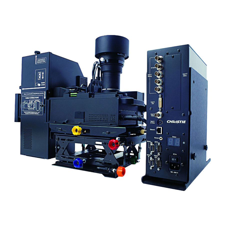
3 Operation This section explains how to operate the projector after it is installed. Read this section and familiarize yourself with the components and menu options before using your projector. About the Projector A brief description of each module is provided in this section. Knowing your projector will help you if troubleshooting is necessary. -
Page 36: Lamps And Mechanical Lamp Changer
Section 3: Operation 3.1.3 Lamps and Mechanical Lamp Changer Integrated with the PHM is the lamp module, which holds two identical 132W or 180W (UHP) lamps. The built-in mechanical lamp changer automatically switches lamps in the event a lamp fails. The non-operating lamp can be replaced while the projector is powered on. -
Page 37: Cooling And Air Vents
Section 3: Operation Lamp expired LASHING YELLOW Keypad command sent - Command received LASHING GREEN Keypad error - Wrong protocol LASHING RED Main Power Switch is located above the AC receptacle on the EM. Turn this switch OFF to cut all power MAIN POWER SWITCH to the projector before unplugging from an AC wall outlet. - Page 38 Section 3: Operation Laser radiation is emitted from the laser diode on the remote. Do not look directly into the beam of the remote. CAUTION LASER RADIATION DO NOT STARE INTO BEAM LASER DIODE Wavelength 670nm Max Output 1mW CLASS II LASER PRODUCT RPMX/RPMSP-D132U &...
-
Page 39: Keypad Commands
Section 3: Operation 3-2 R IGURE EMOTE EYPAD 3.2.1 Keypad Commands When using the keypad, keep these guidelines in mind: • Press keys one-at-a-time; there are no simultaneous key combinations required. RPMX/RPMSP-D132U & RPMSP-D180U User Manual 020-100245-03 Rev. 1 (11-2010) - Page 40 Section 3: Operation • Power and OSD keys —are “press-and-hold” keys that do not function with a typical quick press- OS D and-release key press. • Hold arrow keys down for continuous adjustment/movement in one direction. In serial networks, pause briefly between adjustments to make sure that more distant projectors can keep up with the commands.
- Page 41 Section 3: Operation Cha nnel Channel Select a source setup (channel) defined and stored in projector memory. Enter a 2-digit channel number, the display will automatically update according to the setup parameters defined for that channel. A new channel is automatically created if you adjust an image from a new source.
- Page 42 Section 3: Operation Bright Brightness Increases or decreases the amount of black in the image. Use keys until you reach the required level of contrast. For best results, start high and decrease so that dark areas do not become black (“crushed”). Conversely, overly high brightness changes black to dark gray, causing washed-out images.
- Page 43 Section 3: Operation Func Function Key Using the for special tasks within the menu system is noted with the appropriate topic Func WITHIN A MENU: elsewhere in Section 3. For example, press Func in the Channel Setup menu to enable deletion or copying of a channel.
-
Page 44: Navigating The Menus
Section 3: Operation Arrow Keys Use the keys to change a slidebar value or to select a different option within a drop-down list without having to first scroll through options. See also Editing Text later in Section 3. Use the keys to navigate within a menu, drop-down list or text box. - Page 45 Section 3: Operation Press the number corresponding to the function menu, such as for the Image Settings menu, or use the keys on any keypad to highlight the option, then press . The corresponding function menu or drop-down list of further options will appear. Longer menus have a scroll bar on the right.
- Page 46 Section 3: Operation Using Slidebars and Other Controls Most function menus allow you to change settings by using slidebars, checkboxes, and drop-down lists. To select a slidebar, toggle a checkbox status or view a drop-down list, do one of the following within the function menu: •...
- Page 47 Section 3: Operation keys to navigate up and down the list (the current choice is noted with a small ). Press to choose the highlighted option from the list. Example of Drop-Down List 3-8 E IGURE XAMPLE To scroll through a list without first pulling it down, highlight the option and use .
-
Page 48: Using Inputs And Channels
Section 3: Operation 3-10 A IGURE DDING OR ELETING HARACTERS To accept edits and leave the edit window, press (Enter). NOTES: Exit 1) Press at any time to cancel changes and return to the previously-defined text. 2) Once you enter the first digit, this digit replaces all old digits. 3) Pressing any non-numbered key will accept the number entered up to that point as the new value. -
Page 49: Creating A New Channel
Section 3: Operation If more than one channel exists for the input, the image will be displayed according to the setup parameters for the first channel with matching characteristics. 3-11 C IGURE HANNEL Channel A channel is a collection of measurements, locations and settings that tailor the display of a signal to your specific needs. -
Page 50: Using A Channel
Section 3: Operation 3-12 S IGURE ELECTING A HANNEL 3.4.3 Using a Channel Select a channel at any time by pressing (see right). To prevent a channel from appearing in this list, edit Channel the channel as described in Channel Edit later in this section. NOTE: The current channel is highlighted upon entering the channel list, or, if this channel is not displayed here, the first channel in the list is highlighted. -
Page 51: Copying Or Deleting Channels
Section 3: Operation What Appears in Channel Setup Menu? This menu lists all channels defined and indicates where they are connected on the input panel. The far left column lists channel numbers currently defined. The values in the far right columns indicate horizontal and vertical frequencies—if someone has defined a name for this channel, it appears here. - Page 52 Section 3: Operation If you do not want to copy the current channel, press Exit to cancel and return to the previous menu. 3-15 C IGURE OPYING A HANNEL Deleting a Channel 1. Highlight the channel in the Channel Setup menu. 2.
- Page 53 Section 3: Operation 1. From the presentation level, press to display the main menu. Menu 2. Press , to display the Channel Setup menu or move the highlight to the Channel Setup option and press . The Channel Setup menu will appear. 3.
-
Page 54: Adjusting The Image
Section 3: Operation Adjusting the Image The most commonly used options for image adjustments are accessed through 2 menus: Size and Position ( ) and Image Settings ( ), both appear in the Main menu. From either menu, Menu Menu you can change settings effecting the image from the current channel by working with the appropriate slidebars, checkboxes and drop-down lists. -
Page 55: Resize Presets
Section 3: Operation Use Size and Position controls to match the image precisely to the screen used at the site. You can increase or decrease the size of your image, change its proportion (aspect ratio), move the image to a specific area of the screen, and refine other related parameters. - Page 56 Section 3: Operation No Resizing Displays the image in its native resolution, which may or may not match the projector’s resolution. For example, for a source with a native resolution of 800 x 600, “No Resizing” will use the central 800 x 600 pixels and have a black border—the black border areas are unused areas.
-
Page 57: Size
Section 3: Operation Full Height Fills the display from top-to-bottom. Depending on the source, this may create borders. Anamorphic Displays an anamorphic image in its native 16:9 aspect ratio. The image will fill the screen from side-to-side and be centered between black bars at top and bottom. 3.6.2 Size Controls both the image width and height in tandem, maintaining the current aspect ratio of the displayed signal data. -
Page 58: Pixel Phase
Section 3: Operation 3.6.5 Pixel Phase NOTE: Adjust “Pixel Phase” after “Pixel Tracking”. Adjust pixel phase when the image (usually from an RGB source) still shows shimmer or “noise” after pixel tracking is optimized. Pixel phase adjusts the phase of the pixel sampling clock relative to the incoming signal. For best results, use a good test pattern such as a smooth gray consisting of a clear pattern of black and white pixels, or a similar “half on, half off”... -
Page 59: Image Settings Menu
Section 3: Operation When using SD or HD or a decoded video source at , the default blanking of “0” defines an INPUT 3 INPUT 4 active input window of 720 x 483. 3-21 B IGURE LANKING Blanking (Top, Bottom, Left, and Right) Crop the image so that unwanted edges are removed from the display (changed to black). -
Page 60: Contrast
Section 3: Operation 3-23 I IGURE MAGE ETTINGS 3.7.1 Contrast Changes the perceived difference between light and dark areas of your image (0-100). For best results, keep close to 50 or start with a low value and increase so that whites remain bright but are not distorted or tinted, and that light areas do not become white (“crushed”). -
Page 61: Detail
Section 3: Operation Override only if standard pixel tracking and phase adjustments do not clear up a “noisy” video signal, or if a graphics signal appears overly “soft”. 3.7.5 Detail “Detail” adjusts the sharpness of a video image so that edges remain clearly defined. It can be useful if a “Noise Reduction”... -
Page 62: Video Options - Submenu
Section 3: Operation 3.7.8 Video Options — Submenu 3-26 V IGURE IDEO PTIONS UBMENU This submenu is used only with video sources, INPUTS 3 Enable Decoder AGC Automatic Gain Control (AGC) affects only decoded video images. Enter a checkmark (default) in most instances. - Page 63 Section 3: Operation PAL 60 SECAM France, Eastern Europe, most of Africa NOTE: Use “Auto” for all instances EXCEPT a poor quality input signal or a black-and-white video signal. To detect and display such signals, select the relevant standard from the list. 3-28 I IGURE NPUT...
-
Page 64: Input Levels - Submenu
Section 3: Operation 3.7.9 Input Levels — Submenu 3-29 I IGURE NPUT EVELS UBMENU NOTES: 1) The projector automatically optimizes input levels for most sources. The Input Levels submenu is for experienced users only. 2) Before beginning, verify that overall contrast and brightness settings are near 50 and that color temperature is set up on an internal grayscale test pattern. - Page 65 Section 3: Operation 2. Check the color temperature setup using an internal grayscale test pattern, making sure to obtain a neutral grayscale. NOTE: Not required for “Auto” adjustment. 3. Confirm that you are using an analog source not connected to .
-
Page 66: Advanced Image Settings - Submenu
Section 3: Operation input drives until both black and white edges are just visible and distinguished from neighboring pixels. Images from this source will then display correct blacks and whites without “crushing”. Adjusting Input Levels Using the Peak Detector 1. Display a 16 level grayscale test pattern from the external source. Enter a checkmark in the Peak Detector checkbox. - Page 67 Section 3: Operation 3-32 G IGURE AMMA ABLE PTIONS 3-33 S IGURE ELECT OLOR PTIONS Select Color Adjustment Choose an overall color performance for all images. The “Max Drives” drives all 3 colors at their maximum level so that they are on and cannot be changed. SD Video and HD Video apply a color gamut optimized for standard or high-definition video sources.
-
Page 68: Color Temperature
Section 3: Operation Color Temperature Adjust to apply a specific and accurate color temperature to all displays. Color temperatures are expressed in degrees Kelvin (3200-9300K), and utilize different combinations of the projector’s original native color primaries to produce a “coloration” or cast in images. The lower the temperature the more reddish the cast; the higher the temperature, the more bluish the cast. -
Page 69: 4: Advanced Configuration And Controls
4 Advanced Configuration and Controls The Configuration menu provides access to diagnostics and calibration tools and the Service submenu (password-protected). Use the Configuration menu to define general operating parameters and communica- tions with other projectors and equipment, and to access other advanced processing and image adjustments affecting overall performance. -
Page 70: Set Date & Time
Section 4: Advanced Configuration and Controls Set Date & Time Enter/read the current year-month-day and hour-minute-second. Changes here reset the projector’s real-time clock. Menu Preferences — Submenu Use the options in this submenu to adjust the appearance, content and/or location of on-screen menus and messages. -
Page 71: Communications
Section 4: Advanced Configuration and Controls DISPLAY ERROR MESSAGES Choose how you want to be notified of errors detected in either the incoming signal or projector. Select “Screen” or “All” to see a brief on-screen message or select “RS-232” to receive messages via RS-232 (or RS-422) serial communica- tion only. -
Page 72: Network Routing
Section 4: Advanced Configuration and Controls Proj key in 3.2, Using the Keypads). If you make a mistake in assigning or changing the projector number, Exit press to cancel. 4.7.3 Network Routing Not applicable for stand-alone projectors or simple serial networks with only one type of controller and NOTE: linking. -
Page 73: Ethernet Settings (Submenu)
Section 4: Advanced Configuration and Controls 4.7.4 Ethernet Settings (Submenu) Recommended for network administrators only. NOTE: DHCP Enable this checkbox if you want a DHCP server to automatically assign an IP address that is valid and unique for use on the current Ethernet network. On networks without a DHCP server, or to override the automatic DHCP server function, delete the checkmark and enter the new “IP Address”... -
Page 74: Broadcast Key
Section 4: Advanced Configuration and Controls ARTNET BASE CHANNEL When advanced mode is enabled, the projector listens to data on 64 consecutive channels or 10 consecutive channels when not enabled. The projector processes requests beginning with the ‘base channel’ defined here. The requests implement these functions: FUNCTION VALUE CHANNEL... -
Page 75: Wired Keypad Protocol
Section 4: Advanced Configuration and Controls 4.7.7 Wired Keypad Protocol Select “On” to enable use of a wired remote keypad connected to the rear of the projector. The projector will then respond to incoming commands from either port. To disable the wired keypad, use a different keypad (the built-in or an IR remote keypad) to select “off”. -
Page 76: Brightness Uniformity - Submenu
Section 4: Advanced Configuration and Controls 4.8.3 Brightness Uniformity — Submenu 4-8 B IGURE RIGHTNESS NIFORMITY UBMENU Provides refinement of displays already matched for their primary colors and overall light output. Use to create a smooth image in which no area appears brighter or more red, green or blue than another. Enable the “Uniformity Enable”... - Page 77 Section 4: Advanced Configuration and Controls 4-10 C IGURE OLOR ERFORMANCE HOICES The projector can utilize any of the 3 pre-defined color performance settings identified in Figure 3.42 (default=User 1), or colors can be driven on the basis of color temperature. For most applications, one of these options will produce accurate and realistic colors from a variety of sources.
- Page 78 Section 4: Advanced Configuration and Controls Color Adjustment by X,Y Use this submenu to alter, add or copy a color gamut (i.e., “color adjustment”). Controls in this menu define the precise hue of each primary color component (red, green, blue, and white) used to generate the millions of colors produced in displays.
-
Page 79: Diagnostics / Calibration
Section 4: Advanced Configuration and Controls Adjust the hue of each primary color (red, green, blue, and white) by using more or less of it in relation to the other colors. 4-13 C IGURE USTOMIZE OLOR 4.13 Using Multiple Projectors for Using Color Saturation procedure. -
Page 80: Color Enable
Section 4: Advanced Configuration and Controls 4.9.4 Color Enable Select which color or colors you want to see. This is useful while working with color temperature, input levels or other special setup parameters. Colors can also be enabled or disabled by entering the corresponding function code listed on the back of the standard remote keypad. -
Page 81: Color Wheel Calibration - Submenu
Section 4: Advanced Configuration and Controls 4.9.6 Color Wheel Calibration — Submenu Adjusts the timing of the color wheel. If the color wheel is incorrectly calibrated, the colors throughout the displayed image will appear in various unmatched shades. 4-16 C IGURE OLOR HEEL... -
Page 82: Working With The Lamp
Section 4: Advanced Configuration and Controls 4.10 Working With the Lamp The RPMX/RPMSP-D132U projectors are installed with two132W UHP lamps and the RPMSP-D180U projectors are installed with two 180W UHP lamps. Only one lamp will be ON at any given time. 4.10.1 The Lamp Menu The Lamp menu provides performance adjustments for the lamp to achieve the brightest, most uniform image for the life of the lamp. - Page 83 Section 4: Advanced Configuration and Controls • power the lamp with a specific wattage Use the lamp mode that best suits your brightness needs. For example, in a tiled display application you may want to precisely match brightness levels between adjacent images – judge by eye and set each individual lamp “Power”...
-
Page 84: Pip And Seamless Switching
Section 4: Advanced Configuration and Controls FAILED TO STRIKE Displays when the projector can not turn a lamp on. This may or may not be lamp related, and may require further investigation by the user before proper servicing can take place. For example, a lamp driver may have failed causing the lamp not to ignite. TURNED OFF UNEXPECTEDLY Displays when a lamp or lamp related component fails. -
Page 85: Working With Pip
Section 4: Advanced Configuration and Controls Decoded signals (Input 3, Input 4, Composite video, S-Video, or any video signal via Input 1 BNC connectors or via an analog option card). Analog Option Cards Digital Option Cards HD interlaced sources are not recommended for the PIP window. NOTE Other PIP or Seamless Switching tips include: •... -
Page 86: Working With Seamless Switching
Section 4: Advanced Configuration and Controls Short cut: Press on the Remote if menu not present. Toggle to display from two sources at once (Picture-in-Picture) or the primary source only. This checkbox turns the secondary source on and off. Disable PIP and Best Switching for Interlaced sources > 35kHz. NOTE: PIP Size and Position –... - Page 87 Section 4: Advanced Configuration and Controls Tips: • Make sure a channel is configured for each source. • Progressive digital and analog sources are recommended. • Set Image Optimization to Seamless Switching (see below). • For best results, use the same frame rate and gamma setting for each. Avoid using two Interlaced sources.
-
Page 88: Status Menu
Section 4: Advanced Configuration and Controls in this manner all of the time, even with single displays. For normal keypad function, select Never (default). Set to When PIP Active to activate number keys only when PIP is in use. Numbers Select Main Image keypad functionality works only when menus are closed. NOTE: 4.12 Status Menu The read-only Status menu lists a variety of details about the standard and optional components currently... -
Page 89: Color Adjustment Procedure
Section 4: Advanced Configuration and Controls 4.14.2 Color Adjustment Procedure After the Color Primary Settings are calibrated for the site (see Section 4.14.1 Preliminary Calibration), use the Color Adjustments by X,Y or Color Saturation menu to refine each projector’s fundamental colors. The hue and intensity of each color must appear the same from one display to another. - Page 90 Section 4: Advanced Configuration and Controls 4-21 C X/Y V IGURE ALUES INTO ROJECTORS 6. In each projector, judge by eye and adjust x/y coordinates slightly in the following manner: • To match reds, decrease “ Red X” until full field red screens match. •...
-
Page 91: Using The Color Saturation Menu For Color Matching
Section 4: Advanced Configuration and Controls These coordinate adjustments move the 3 color points closer together to establish a “shared” gamut attainable by all projectors in the group. Adjust only as necessary to make sure that the resulting color palette is as large as possible. - Page 92 Section 4: Advanced Configuration and Controls Before You Begin Read through the entire procedure before attempting to adjust Brightness Uniformity controls, and keep in mind the following list of prerequisites and guidelines: • Adjust the primary colors as described in Section 4.14 Matching Colors In Multiple ADJUST COLORS FIRST—...
- Page 93 Section 4: Advanced Configuration and Controls c. Select the 13 Point test pattern for display. This pattern provides 9 screen “zones” with 13 targets. FOR BEST RESULTS: Rather than examining the CENTER of each zone when assessing Brightness Uniformity adjustments, focus on extreme EDGES as indicated in the illustration at right. d.
- Page 94 Section 4: Advanced Configuration and Controls Make sure that overall light output remains well-matched from one screen center to the next. Where necessary, increase or decrease Lamp Power to recover center matches. Step 2: Adjust Color (level of red/green/blue) in 8 Zones NOTES: 1) Ignore the brightness of individual zones.
-
Page 95: Edge Blending (Sxga Only)
Enable” checkbox at the top of the Brightness Uniformity menu. Christie Edge Blending is an innovative set of software functions that can blend white levels along the edges of multiple adjacent projected images to create a single seamless larger image. - Page 96 Section 4: Advanced Configuration and Controls 4-25 E IGURE LENDING ONCEPT For best results, use the same projector model and type throughout your display wall. Avoid high-gain screens whenever possible—the optical performance of such screens demands minimal image offset, thus projectors must be located very close to one another.
-
Page 97: Edge Blending Procedure
Section 4: Advanced Configuration and Controls 4-27 “M ” E IGURE IDPOINT XAMPLES Other Functions For convenience, the Edge Blending submenu also includes related options for enabling a specific color and/or test pattern, or for working with colors or the lamp. Such functions duplicate those provided elsewhere in the menu system. -
Page 98: Remote Control Of The Projector
RS-422 ports or the RS-232 In port. Connect all ports, if desired. For complete information, including a list of valid ASCII messages and how to structure them for use, obtain the current Christie Serial Communications document. 4.17 Error Conditions Occasionally the projector will encounter an error condition that can interrupt normal operation. This can be caused by a simple invalid keypad entry, an input signal error (most common) or a system error. -
Page 99: User Errors
Section 4: Advanced Configuration and Controls • To disable error messages (except for “invalid user key entry”, which can’t be hidden), select “ ”. The 2-digit error code that corresponds to the message appears in the status display window on the electronics module. -
Page 100: System Warnings / Errors
GENERAL Software bug. Contact dealer/factory. Flash memory corrupted. Download new software. Engineering-only programming is complete. Call Christie, replace TIPM. Attempting to download code without being in boot mode. Invalid interrupt. Power off/on. If it persists, contact dealer/factory. Attempting to program boot mode without jumper. - Page 101 Section 4: Advanced Configuration and Controls CODE DESCRIPTION LAMP FAILURES Lamp 1 Failed to Strike Lamp 1 Turned Off Unexpectedly Lamp 2 Failed to Strike Lamp 2 Turned Off Unexpectedly Lamp Position Failure Lamp 1 Card Not Installed Lamp 2 Card Not Installed POWER AND COOLING TIPM (EM) Fan Failure Lamp Fan Failure...
- Page 102 Section 4: Advanced Configuration and Controls CODE DESCRIPTION Unable to program the Backplane module Unable to program the Warp Module Error LED Status Located next to the 2-digit status display is a single LED that will illuminate one of three colors to convey the current status of the system.
-
Page 103: Warnings And Safety Guidelines
For protection from ultraviolet radiation, keep all projector shielding intact during operation. Installation must be performed by CHRISTIE accredited service technicians 5.1.1 Labels and Markings Observe and follow all warnings and instructions marked on the projector. -
Page 104: Projector Location
Allow a lamp to cool before handling and/or powering down and unplugging the projector. Use only the lamps supplied by CHRISTIE, in the Lamp Replacement Kit for these projectors. RPMX/RPMSP-D132U & RPMSP-D180U User Manual 020-100245-03 Rev. 1 (11-2010) -
Page 105: Power Cord And Attachments
Section 5: Maintenance 5.1.5 Power Cord and Attachments Use only the attachment accessories recommended by CHRISTIE. Use of others may result in the risk of fire, shock or personal injury. Use only the AC power cord supplied. Do not operate if the AC supply exceeds the specified voltage and power range. -
Page 106: Cleaning And Maintenance Guide
Section 5: Maintenance Do not service the projector while it is connected to AC. There are exposed voltages that could cause severe physical injuries and possibly death. Disconnect the projector from AC and wait 2 minutes to allow the capacitors on the power supply to discharge before removing the projector’s covers. -
Page 107: Replacing Remote Batteries
Section 5: Maintenance Replacing Remote Batteries The IR remote uses (2) AA size - 1.5V alkaline batteries. 1. Remove the back cover. See Figure 5-1 Replacing Remote Batteries. 2. Replace the batteries. The proper positive/negative orientation is indicated by the etching in the bottom of the compartment. -
Page 108: Replacing A Lamp
Section 5: Maintenance 5.4.1 Replacing a lamp 1. Press to power down the projector. Wait for the internal cooling fans to stop. Turn the main power switch OFF. Allow the lamps to cool for an additional 5 minutes before continuing with Step 2. The projector must be powered OFF when replacing a lamp. - Page 109 Section 5: Maintenance Do not stick your hands in an empty lamp compartment. 6. Touch the new only lamp by its handle. Align it with the terminal plug located on the side wall of the lamp compartment. Insert the lamp all the way in until it is fully seated – the lamp connector will plug into the terminal plug.
-
Page 111: Displays
6 Troubleshooting If the projector is not operating properly, note the symptoms and use this guide to assist you. If you cannot resolve the problems yourself, contact your dealer for assistance. NOTE: A qualified service technician is required when opening the projector to diagnose any “probable cause”. - Page 112 Section 6: Troubleshooting The upper portion of the display is waving, tearing or jittering This can sometimes occur with video or VCR sources. Check your source. Portions of the display are cut off or wrap to the opposite edge Resizing and/or blanking may need adjustment. The display appears compressed (vertically stretched) 1.
-
Page 113: Lamps
Section 6: Troubleshooting 3. The input signal and/or signal cables carrying the input signal may be of poor quality. 4. If the distance between the input source device and the projector is greater than 25 feet, signal amplifica- tion/conditioning may be required. 5. -
Page 115: Display
7 Specifications Due to continuing research, specifications are subject to change without notice. Specifications apply to all models unless otherwise noted. Display RPMSP-D132U RPMX-D132U RPMSP-D180U RESOLUTION SXGA+ (1400x1050) XGA (1024 x 768) SXGA+ (1400x1050) BRIGHTNESS 132W White Boost ON 2320 lumens... -
Page 116: Inputs
Section 7: Specifications Inputs Applies to RPMX/RPMSP-D132U and RPMSP-D180U (Interlaced or Progressive Scan Format) ANALOG RGB OR YPRPB Pixel Clock Rate 13 – 210 MHz max Color Space RGB or YPbPr ±2dB Input Levels: R, G, B, - with sync: 1.0V ±2dB R, G, B, - without sync:... - Page 117 Section 7: Specifications COMPOSITE VIDEO AND S-VIDEO Signal Formats Composite-video S-video (CVBS) (Y/C) Video Standards NTSC, NTSC 4.43, PAL, PAL M, PAL N, PAL60, SECAM 1.0Vp-p ±3db Input Levels Composite-video (including sync tip) 1.0Vp-p ±3dB S-video luma (Y): (including sync tip) S-video chroma (C) 630mV nominal (burst)
-
Page 118: Power Requirements
WIRED CONTROL 3.5mm plug Connector Type Input Levels High: 2.2V min. Low: 0.9V max. Power: 500mA @ 5V Power Requirements RPMX-D132U RPMSP-D132U RPMSP-D180U GENERAL Voltage Range 100 – 240 VAC nominal 100 – 240 VAC nominal 100 – 240 VAC nominal Line Frequency 50 –... -
Page 119: Lamps
Section 7: Specifications Lamps NOTE: The projector uses two identical lamps; however only one lamp operates at any given time. RPMSP-D180U RPMX/RPMSP-D132U Type 132W Philips UHP 180W Philips UHP Power 120 - 132 Watts 160 - 180 Watts ± 20 deg. tilt from horizontal ±... -
Page 120: Environmental
Section 7: Specifications EN61000-4-11 Voltage Dips, Short Interruptions and Voltage Variations Immunity Environmental Operating Environment Temperature 5°C to 30°C (40°F to 86°F) Humidity 20% - 80% non-condensing Altitude 0 - 10,000ft, -5°C to 50°C Non-Operating Environment Temperature -25°C to 70°C with relative humidity varying between 0% to 95% Altitude 30,000ft, -25°C to 70°C Standard Components... -
Page 121: A Cable Connections
A Cable Connections A serial link of RS-232 or RS-422 enables ASCII communication with the projector so that it can be controlled remotely from a PC or other controller. From a PC, connect a standard 9-wire RS-232 serial cable to the RS-232 port. -
Page 122: Projector To Projector
Appendix A: Cable Connections A.3 Projector to Projector RPMX/RPMSP-D132U & RPMSP-D180U User Manual 020-100245-03 Rev. 1 (11-2010) -
Page 123: B Dimensions & Mounting Information
B Dimensions & Mounting Information B.1 Horizontal Configuration B-1 H IGURE ORIZONTAL ONFIGURATION RPMX/RPMSP-D132U & RPMSP-D180U User Manual 020-100245-03 Rev. 1 (11/10) -
Page 124: Vertical Configuration
Appendix B: Dimensions & Mounting Information B.2 Vertical Configuration B-2 V IGURE ERTICAL ONFIGURATION RPMX/RPMSP-D132U & RPMSP-D180U User Manual 020-100245-03 Rev. 1 (11-2010) -
Page 125: Horizontal Configuration For Sxga
Appendix B: Dimensions & Mounting Information B.3 Horizontal Configuration for SXGA RPMX/RPMSP-D132U & RPMSP-D180U User Manual 020-100245-03 Rev. 1 (11-2010) -
Page 126: D132U Horizontal Configuration For Xga
Appendix B: Dimensions & Mounting Information B.4 D132U Horizontal Configuration for XGA RPMX/RPMSP-D132U & RPMSP-D180U User Manual 020-100245-03 Rev. 1 (11-2010) -
Page 127: C System Integration
C System Integration The GPIO connector located on the input panel provides a flexible method of interfacing external I/O devices to the projector. There are 7 GIO pins on the 9 pin GPIO connector, which are configurable via RS-232 commands. The other two pins are reserved for ground and power. See Table C.1 for pin identification. Table C.1 GPIO Pins PIN NUMBER SIGNAL... -
Page 128: Real Time Event
Appendix C: System Integration Query Command Request the state and configuration of all pins (GIO?) (GIO! “HHLLHLH” “OOIOOOI”) Reply with pin state and configuration (GIO? C2) Request the configuration for pin #2 Reply with pin #2 configuration as output (GIO! C2 O) (GIO? 2) Request the state of pin #2 (GIO! H) -
Page 129: D Optional Input Modules
D Optional Input Modules There are many optional input modules and accessories currently available for this projector. Contact your dealer for a complete and up-to-date listing. NOTE: Always unplug the projector or switcher before installing or removing any optional input module. D.1 RGB500 Input Module 38-804606-xx The RGB500 Input Module may be installed in this projector, a Marquee Signal Switcher, or a Marquee Case/ Power Supply. -
Page 130: Rgb400 Active Loop-Thru Input Module 38-804607-Xx
Appendix D: Optional Input Modules D.3 RGB400 Active Loop-Thru Input Module 38-804607-xx The RGB400 ALT Input Module may be installed in this projector, a Marquee Signal Switcher, or a Marquee Case/Power Supply. The module receives analog RGB input signals from computers or other RGB source devices. -
Page 131: Serial Digital Input Module 38-804602-Xx
Appendix D: Optional Input Modules Features ‡supports Digital Visual Interface (DVI) single-channel ‡supports VESA® Extended Display Identification Data (EDID™) ‡provides an active-loop-through using a DVI connector (conforming to the DVI Specification) D.6 Serial Digital Input Module 38-804602-xx This module accepts a serial digital 4:2:2 component video signal (YCbCr) via a single SERIAL IN connector. - Page 132 Appendix D: Optional Input Modules Dual SD/HD-SDI Features ‡accepts and decodes up to two serial digital inputs ‡outputs up to two 10-bit YCbCr 4:2:2 video signals ‡provides input(s) to output(s) loop-through capability ‡supplies interchangeable inputs as part of the Picture-in Picture display RPMX/RPMSP-D132U &...
- Page 134 Section : Corporate offi ces Worldwide offi ces USA – Cypress United Kingdom Hungary/Eastern Europe Beijing ph: 714-236-8610 ph: +44 118 977 8000 ph: +36 (0) 1 47 48 100 ph: +86 10 6561 0240 Canada – Kitchener Germany Singapore Korea ph: 519-744-8005 ph: +49 2161 664540...
Need help?
Do you have a question about the RPMX-D132U and is the answer not in the manual?
Questions and answers