ADTRAN ATLAS 800 SERIES System Manual
Atlas 800 series
Hide thumbs
Also See for ATLAS 800 SERIES:
- Specification sheet (2 pages) ,
- User manual (50 pages) ,
- User manual (190 pages)
Table of Contents
Advertisement
Quick Links
61200780L1-1C
August 2004
ATLAS 800 SERIES
System Manual
1200780L1
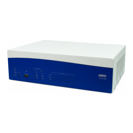
ATLAS 830 System, AC
1200781L1
ATLAS 830 System, DC
1200321L1
ATLAS 890 System
1200322L1
ATLAS 890 System Controller Module
1200185L3
Quad T1/PRI Option Module
1200264L1
Quad E1/PRA Option Module
1200184L1
Quad Nx 56/64 Option Module
4200261Lx
Quad USSI Option Module
1200186L2
Octal Basic Rate ISDN (U-Interface) Option Module
1200343L1
Octal Basic Rate ISDN (S/T Interface) Option Module
1200223L1
T3 Option Module
1200225L1
T3 Option Module with Drop and Insert Interface
4200773Lx
Dual Video Option Module
1200771L1
NxT1 HSSI/V.35 Option Module
1200338L1
Octal FXS Option Module
1200221Lx
8,16,24,32 Channel Voice Compression Resource Modules
1200262L1
Nx 56/64 BONDing Resource Module
1200222L1
HDLC Resource Module
1200181L1
Modem-16 Resource Module
1200782L1
Modem-24 Resource Module
1200182L1
Async-232 Option Module
Advertisement
Chapters
Table of Contents

Related Manuals for ADTRAN ATLAS 800 SERIES


Summary of Contents for ADTRAN ATLAS 800 SERIES
- Page 1 ATLAS 800 SERIES System Manual 1200780L1 ATLAS 830 System, AC 1200781L1 ATLAS 830 System, DC 1200321L1 ATLAS 890 System 1200322L1 ATLAS 890 System Controller Module 1200185L3 Quad T1/PRI Option Module 1200264L1 Quad E1/PRA Option Module 1200184L1 Quad Nx 56/64 Option Module...
-
Page 2: About This Manual
To the Holder of the Manual The contents of this manual are current as of the date of publication. ADTRAN reserves the right to change the contents without prior notice. In no event will ADTRAN be liable for any special, incidental, or consequential damages or for commercial losses even if ADTRAN has been advised thereof as a result of issue of this publication. -
Page 3: Revision History
ATLAS 800 Series System Manual Revision History Revision History Document Date Description of Changes Revision Aug 2002 Initial release. Jan 2004 Added Modem-24 Module. Combined ATLAS 830 and ATLAS 890 into one manual. Aug 2004 Corrections to menu selections. Conventions Notes provide additional useful information. -
Page 4: Safety Instructions
ATLAS 800 Series System Manual Safety Instructions Safety Instructions When using your telephone equipment, please follow these basic safety precautions to reduce the risk of fire, electrical shock, or personal injury: 1. Do not use this product near water, such as a bathtub, wash bowl, kitchen sink, laundry tub, in a wet basement, or near a swimming pool. - Page 5 Advance notification and the opportunity to maintain uninterrupted service are given. 4. If experiencing difficulty with this equipment, please contact ADTRAN for repair and warranty information. The telephone company may require this equipment to be disconnected from the network until the problem is corrected or it is certain the equipment is not malfunctioning.
-
Page 6: L1-1C © 2004 Adtran, Inc
ATLAS 800 Series System Manual FCC-Required Information FCC Radio Frequency Interference Statement This equipment has been tested and found to comply with the limits for a Class A digital device, pursuant to Part 15 of the FCC Rules. These limits are designed to provide reasonable protection against harmful interference when the equipment is operated in a commercial environment. -
Page 7: L1-1C © 2004 Adtran, Inc
ATLAS 800 Series System Manual Affadavits Affadavits Affidavit Requirements Connection to Digital Services • An affidavit is required to be given to the telephone company whenever digital terminal equipment without encoded analog content and billing protection is used to transmit digital signals containing encoded analog content which are intended for eventual conversion into voiceband analog signal and transmitted on the network. - Page 8 ATLAS 800 Series System Manual Affadavits Affidavit for Connection of Customer Premises Equipment to 1.544 Mbps and/or Subrate Digital Services For the work to be performed in the certified territory of ___________________ (telco name) State of ________________ County of ________________...
- Page 9 ATLAS 800 Series System Manual Industry Canada Compliance Information Industry Canada Compliance Information Notice: The Industry Canada label applied to the product (identified by the Industry Canada logo or the “IC:” in front of the certification/registration number) signifies that the Industry Canada technical specifications were met.
-
Page 10: Product Warranty
ATLAS 800 Series System Manual Product Warranty Product Warranty ADTRAN will repair and return this product within the warranty period if it does not meet its published specifications or fails while in service. Warranty information can be found at www.adtran.com. Product Registration Registering your product helps ensure complete customer satisfaction. - Page 11 Your reseller should serve as the first point of contact for support. If additional pre-sales support is needed, the ADTRAN Support web site provides a variety of support services such as a searchable knowledge base, latest product documentation, application briefs, case studies, and a link to submit a question to an Applications Engineer.
- Page 12 These courses include overviews on product features and functions while covering applications of ADTRAN's product lines. ADTRAN provides a variety of training options, including customized training and courses taught at our facilities or at your site. For more information about training, please contact your Territory Manager or the Enterprise Training Coordinator.
-
Page 13: Table Of Contents
ADTRAN Utilities ........ - Page 14 SECTION 1 ENGINEERING GUIDELINES Assists network designers in incorporating the ATLAS 800 Series System into existing networks. Includes pinouts. Table of Contents ATLAS 830 Description............. . 23 Equipment Dimensions .
- Page 15 ATLAS 800 Series System Manual Engineering Guidelines List of Pinouts Pinout 1. ATLAS 830 CRAFT Port (DB-9, female) ........24 Pinout 2.
-
Page 16: Atlas 830 Description
ATLAS 830 MODULES POWER STATUS SYSTEM TES T TES T CRAFT ONLINE ETHERNET ERR OR ERR OR REMOTE ALARM ALARM TES T System LEDs Switch Module Status LEDs Figure 1. ATLAS 830 Front Panel Layout 61200780L1-1C © 2004 ADTRAN, Inc. -
Page 17: Aco Switch
ATLAS 800 Series System Manual ATLAS 830 Front Panel Engineering Guidelines ACO Switch switch clears the Alarm Relay (located on the rear panel) after an alarm condition has occurred. If an alarm condition is corrected and then reoccurs, the Alarm Relay activates again. - Page 18 ATLAS 800 Series System Manual ATLAS 830 Front Panel Engineering Guidelines Table 1. ATLAS 830 Front Panel LEDs’ Purpose (Continued) Purpose Network Displays the status of the two built-in T1/PRI interfaces on the rear panel of the unit. (These are referred to in the menus as Slot 0, Ports 1 and 2.) Indicates that the network interface has passed self-test and is operating correctly.
-
Page 19: Table 2. Atlas 830 Led Descriptions
ATLAS 800 Series System Manual ATLAS 830 Front Panel Engineering Guidelines Table 2. ATLAS 830 LED Descriptions For these LEDs... This color light... Indicates that... System Power Red (solid) Power supply error condition or temperature alarm. Green The unit is on and connected to a power source. -
Page 20: Atlas 830 Rear Panel
ATLAS 800 Series System Manual ATLAS 830 Rear Panel Engineering Guidelines Table 2. ATLAS 830 LED Descriptions (Continued) For these LEDs... This color light... Indicates that... Modules Status Green (solid) Module is present. Green (fast blink) Module has been manually taken offline by the user. -
Page 21: Admin Port
ATLAS 800 Series System Manual ATLAS 830 Rear Panel Engineering Guidelines T1/PRI Power On/Off ADMIN Ethernet Alarm Interfaces Switch Port Port Contacts Slot 1 Slot 5 Slot 2 Slot 6 Slot 3 Slot 7 Slot 4 Slot 8 Option Module Slots Power Supply Figure 2. -
Page 22: 10/100Baset Connection
ATLAS 800 Series System Manual ATLAS 830 Rear Panel Engineering Guidelines 10/100BaseT Connection The 10/100BaseT port (RJ-45) provides a 10/100BaseT Ethernet LAN connection, which is used for IP Routing, TFTP, SNMP, and Telnet connections (see Pinout 3). Pinout 3. ATLAS 830 Ethernet (RJ-45) -
Page 23: Atlas 830 At-A-Glance Specifications
ATLAS 800 Series System Manual ATLAS 830 At-A-Glance Specifications Engineering Guidelines Pinout 5. ATLAS 830 T1/PRI Name Description RxData-Ring Receive data from the network RxData-Tip Receive data from the network Unused — TxData-Ring (R1) Send data towards the network TxData-Tip... - Page 24 ATLAS 800 Series System Manual ATLAS 830 At-A-Glance Specifications Engineering Guidelines Table 3. ATLAS 830 Specifications (Continued) Application Feature Specification Switching Applications ISDN signaling types National ISDN Lucent 5E AT&T 4ESS (PRI Only) Northern DMS-100 (Nortel Custom) Euro ISDN T1 signaling types...
- Page 25 ATLAS 800 Series System Manual ATLAS 830 At-A-Glance Specifications Engineering Guidelines Table 3. ATLAS 830 Specifications (Continued) Application Feature Specification Frame Relay Packet throughput 7900 pkts/sec (based on 64 byte size packets) Management signaling UNI (user and network) interfaces Management signaling types ANSI T1.617-D (Annex D)
-
Page 26: Atlas 890 Description
ATLAS 800 Series System Manual ATLAS 890 Description Engineering Guidelines Table 3. ATLAS 830 Specifications (Continued) Application Feature Specification IP Routing Route discovery RIP V1 RIP V2 ICMP IARP UDP Relay SNMP support RFCs 1315, 1213, 1406 Adtran Enterprise MIB... -
Page 27: Atlas 890 Front Panel
ATLAS 800 Series System Manual ATLAS 890 Front Panel Engineering Guidelines ATLAS 890 FRONT PANEL The front panel contains the Alarm Cut-off ( ) switch, the port, and the controller and option CRAFT modules, and system (fans and alarm) status . -
Page 28: Craft Port
ATLAS 800 Series System Manual ATLAS 890 Front Panel Engineering Guidelines CRAFT Port Use the port (see Pinout 6) to connect to a computer to configure the system via an EIA-232 CRAFT connection or to connect to a modem. Pinout 6. ATLAS 890 CRAFT Port (RJ-48C) -
Page 29: Table 5. Atlas 890 Led Description
ATLAS 800 Series System Manual ATLAS 890 Front Panel Engineering Guidelines Table 4. ATLAS 890 Front Panel LEDs’ Purpose (Continued) Purpose Option Module Displays by row the operational condition of each module installed in the option slots. All LEDs will be off if no option module is installed. (See Table 5 on page 29.) - Page 30 ATLAS 800 Series System Manual ATLAS 890 Front Panel Engineering Guidelines Table 5. ATLAS 890 LED Description (Continued) For These Leds... This Color Light... Indicates That... Active controller Status Green Card is not ready. (slow blink) Green Card is not supported.
-
Page 31: Atlas 890 Rear Panel
ATLAS 800 Series System Manual ATLAS 890 Rear Panel Engineering Guidelines ATLAS 890 REAR PANEL The ATLAS 890 rear panel contains 16 slots for housing option modules which provide a variety of additional resources and data ports (see Figure 4). All slots are functionally identical. The ATLAS 890 also contains two slots for housing controller modules and a single slot dedicated for power supply use only. -
Page 32: 10/100Baset Connection
ATLAS 800 Series System Manual ATLAS 890 Rear Panel Engineering Guidelines Pinout 7. ATLAS 890 Admin In (RJ-48C) Name Description Ground—connected to unit chassis Request to send—low control RxData Data received by the ATLAS 890 Data terminal ready TxDATA Data transmitted by the ATLAS 890... -
Page 33: Alarm Relay Connection
ATLAS 800 Series System Manual ATLAS 890 Rear Panel Engineering Guidelines Alarm Relay Connection This connection alerts the user when a pre-selected alarm condition exists. The four-pin, removable terminal block connects with external wiring (see Pinout 9). Refer to DLP-12, Connecting to the ATLAS 890 External Input, for detailed instructions. -
Page 34: Atlas 890 At-A-Glance Specifications
ATLAS 800 Series System Manual ATLAS 890 At-A-Glance Specifications Engineering Guidelines ATLAS 890 AT-A-GLANCE SPECIFICATIONS Table 6 lists the specifications for the ATLAS 890 system. Table 6. ATLAS 890 Specifications Application Feature Specification TDM Applications TDM bandwidth 49 Mbps Full duplex... - Page 35 ATLAS 800 Series System Manual ATLAS 890 At-A-Glance Specifications Engineering Guidelines Table 6. ATLAS 890 Specifications (Continued) Application Feature Specification Frame Relay Packet throughput 11,700 pkts/sec (64-1500 size packets) Management signaling UNI (user and network) interfaces Management signaling types ANSI T1.617-D (Annex D) ITU-T Q.933-A (Annex A)
-
Page 36: Option Module Pinouts
ATLAS 800 Series System Manual Option Module Pinouts Engineering Guidelines Table 6. ATLAS 890 Specifications (Continued) Application Feature Specification IP Routing Route discovery RIP V1 RIP V2 ICMP IARP UDP Relay SNMP support RFCs 1315, 1213, 1406 Adtran Enterprise MIB... -
Page 37: Quad E1/Pra Option Module
ATLAS 800 Series System Manual Option Module Pinouts Engineering Guidelines Quad E1/PRA Option Module Using the provided adapter cables, the DB-62 port of the Quad E1/PRA Option Module (P/N 1200264L1) supplies a DB-15 connection (see Pinout 12). See Pinout 13 for the DB-62 interface pinout. -
Page 38: Quad Nx 56/64 Option Module
ATLAS 800 Series System Manual Option Module Pinouts Engineering Guidelines Quad Nx 56/64 Option Module Using the provided adapter cables, each DB-78 port of the Quad Nx 56/64 Option Module (P/N 1200184L1) supplies a V.35 Winchester-style connection (see Pinout 14). Pinout 15 shows the DB-78 interface pinout. - Page 39 ATLAS 800 Series System Manual Option Module Pinouts Engineering Guidelines Pinout 15. Quad Nx 56/64 Module (DB-78) (Continued) Signal Signal EXT-TXC-A 2/4 DSR-B/RI 1/3 11-17 Not used DSR-A 1/3 CTS-B 1/3 CTS-A 1/3 CHASIS GND CHASIS GND CTS-A 2/4 CST-B 2/4...
-
Page 40: Quad Ussi Option Module
ATLAS 800 Series System Manual Option Module Pinouts Engineering Guidelines Quad USSI Option Module Pinouts 16 through 20 on the following pages describe the available interfaces for the Quad USSI Option Module (P/N 4200261Lx). Pinout 16. Quad USSI Module (DB-78) -
Page 41: Pinout 17. Quad Ussi Module (Eia-530)
ATLAS 800 Series System Manual Option Module Pinouts Engineering Guidelines Pinout 17. Quad USSI Module (EIA-530) Signal Description Signal Description Signal Description Shield (Ground) Carrier Detect (B) Request to Send (B) Transmit Data (A) Ext. Transmit Clock (B) DTE Ready (A) -
Page 42: Pinout 19. Quad Ussi Module (Rs-232)
ATLAS 800 Series System Manual Option Module Pinouts Engineering Guidelines Pinout 19. Quad USSI Module (RS-232) Signal Description Signal Description Shield (Ground) Sec. Transmit Data Transmit Data DCE Transmit Clock Received Data Sec. Received Data Request to Send Receive Signal Element Timing... -
Page 43: Octal Bri Isdn (U-Interface) Option Module
ATLAS 800 Series System Manual Option Module Pinouts Engineering Guidelines Octal BRI ISDN (U-Interface) Option Module Each port of the Octal BRI ISDN (U-Interface) Option Module (P/N 1200186L2) uses a single RJ-45 jack to connect to a standard BRI U interface circuit (see Pinout 21). -
Page 44: Async-232 Option Module
ATLAS 800 Series System Manual Option Module Pinouts Engineering Guidelines Async-232 Option Module Using the provided adapter cables, each Async-232 Option Module (P/N 1200182L1) interface provides a DB-25 (see Pinout 23). Pinout 23. Async-232 Option Module (DB-25) Name Description Shield... -
Page 45: T3 Drop And Insert Option Module
ATLAS 800 Series System Manual Option Module Pinouts Engineering Guidelines T3 Drop and Insert Option Module Using the provided RG-59, 75-Ohm cables (P/N 3125I054), each T3 Drop and Insert Option Module (P/N 1200225L1) provides BNC connectors for primary and secondary transmit and receive connections (see Pinout 25 Pinout 25. -
Page 46: Pinout 27. Dual Video Module (V.35 Winchester)
ATLAS 800 Series System Manual Option Module Pinouts Engineering Guidelines Pinout 27. Dual Video Module (V.35 Winchester) CCITT Name Description Protective ground Signal ground Request to send from DTE Clear to send to DTE Data set ready to DTE Received line signal detector to DTE —... -
Page 47: Pinout 28. Dual Video Module (Eia-530)
ATLAS 800 Series System Manual Option Module Pinouts Engineering Guidelines Pinout 28. Dual Video Module (EIA-530) Signal Description Signal Description Signal Description Shield (Ground) Carrier Detect (B) Request to Send (B) Transmit Data (A) Ext. Transmit Clock (B) DTE Ready (A) -
Page 48: Nxt1 Hssi/V.35 Option Module
ATLAS 800 Series System Manual Option Module Pinouts Engineering Guidelines NxT1 HSSI/V.35 Option Module The NxT1 HSSI/V/35 Option Module (P/N 1200771L1) uses a single 50 pin SCSI-II interface (or V.35 interface using an optional adapter cable) to combine eight T1s of data (a combination of eight using the four NxT1 HSSI/V.35 Module T1 ports and other T1 ports installed in the system). -
Page 49: Octal Fxs Option Module
ATLAS 800 Series System Manual Option Module Pinouts Engineering Guidelines Pinout 31. NxT1 HSSI/V.35 Module (50-pin SCSI-II and V.35 Winchester) (Continued) Direction Description (+ Side) (- Side) V.35 SD Send Data — V.35 DCD - Data Carrier Detect 17-18 —... -
Page 50: Section 2 System Description
SECTION 2 SYSTEM DESCRIPTION Provides managers with an overview of the ATLAS 800 Series System. This section contains general information and describes physical and operational concepts, card functions, network relationships, provisioning, testing, alarm status, and system monitoring. This section should be used in conjunction with Section 1, Engineering Guidelines, on page 14 of the system manual. -
Page 51: System Overview
It contains a high-performance CPU and powerful communications drivers which support applications such as frame relay and call switching. With the ATLAS 800 Series, you can consolidate voice, data, and video applications into a single platform while optimizing wide-area bandwidth and reducing equipment costs. The ATLAS 800 Series architecture’s expansion slots allows for a variety of modules, making it one of the most versatile access... -
Page 52: Signaling Support
ATLAS 800 Series System Manual Features and Benefits System Description Signaling Support • ISDN D Channel • Robbed Bit, E&M, Ground Start, Loop Start • Convert between Robbed Bit Signaling and ISDN D Channel • Direct Inward Dialing ISDN Switch Types •... -
Page 53: Ppp Switching
ATLAS 800 Series System Manual Option Modules Overview System Description PPP Switching • Supports up to 100 simultaneous PPP connections. • Performs PAP, CHAP, or EAP authentication methods on a per connection basis. • Includes keepalive functionality for PPP connections. -
Page 54: Atlas 890 System Controller Module (P/N 1200322L1)
ATLAS 800 Series System Manual Option Modules Overview System Description Each option module provides a variety of performance and alarm status information. Several features of each module are user-configurable, although default values reflect the most common configurations. All option modules contain an extensive self-test as well as tests designed for the technologies they incorporate. -
Page 55: T3 Option Module (P/N 1200223L1)
The Octal FXS Option Module provides eight analog voice-grade interfaces. Each interface provides talk battery, off-hook supervision, E&M signaling conversion, and ringing in loop-start or ground-start operation. Call progress tones, where necessary, are provided to the modules by the ATLAS 800 Series. 8,16,24,32 Channel Voice Compression Resource Modules (P/N 1200221Lx) The Voice Compression Resource Module (VCOM Module) combines with other ATLAS 800 Series components to implement voice over frame relay (VoFR) capability. -
Page 56: Hdlc Resource Module (P/N 1200222L1)
The Modem-16 Resource Module is a high-capacity card for the ATLAS 800 Series, capable of processing 16 modem or ISDN Calls. Modem or ISDN calls are presented to the ATLAS 800 Series via one or more Primary Rate ISDN (PRI), Basic Rate ISDN (BRI), or T1 circuits. The Modem-16 Resource Module combines with the Async-232 Module to enable dial-up access for up to 32 users. -
Page 57: Section 3 Network Turnup Procedures
Contents of ADTRAN Shipment ........ -
Page 58: Introduction
ADTRAN Customer Service (see the contact information in the front of this manual). Contents of ADTRAN Shipment Table 1 lists the items included in your ADTRAN shipment. Customers must supply a DB-9 male console cable for VT100 terminal/terminal emulation connection and an Ethernet cable. -
Page 59: Grounding Instructions
ATLAS 890 19-23” Convertable Rackmount brackets and screws RJ-45—DB-25 adapter (1 for modem connection) RJ-45 control port cable (1) - ADTRAN P/N 3127004 RJ-45—DB-9 adapter (1) GROUNDING INSTRUCTIONS The following grounding information is from the Underwriters’ Laboratory UL60950 Standard for Safety of Information Technology Equipment Including Electrical Business Equipment, Third Edition, December 1, 2000. -
Page 60: Supplying Power To The Unit
ATLAS 800 Series System Manual Supplying Power to the Unit Network Turnup Procedures SUPPLYING POWER TO THE UNIT AC-Powered Systems The AC-powered ATLAS 830 and ATLAS 890 come equipped with a detachable 6-foot power cord with a 3-prong plug for connecting to a grounded power receptacle. As shipped, the ATLAS is set to factory default conditions. -
Page 61: Mounting Options
ATLAS 800 Series System Manual Mounting Options Network Turnup Procedures MOUNTING OPTIONS The ATLAS 830 may be used on a tabletop or installed in a 19-inch or 23-inch rackmount configuration. The ATLAS 890 must be rackmounted. For rackmount installations, the ATLAS allows flush-face mount, face-forward mount, and center mount (see Figure 1). -
Page 62: Installing Network And Option Modules
ATLAS 890. (Slots 7 and 8 of the ATLAS 830 may also be used for an optional redundant power supply.) The two units share the same ATLAS 800 Series option module cards. However, the controller slots of the ATLAS 890 only accept ATLAS 890 controller modules. -
Page 63: Modules Installation Instructions
• Quad E1/PRA Option Module Quick Start Guide • One DB-62 to Quad DB-15 female cable, ADTRAN P/N: 3125I061 The Quad E1/PRA Option Module may also be purchased with BNC Network Connection Interfaces (P/N 4200264L1). Quad Nx 56/64 Option Module (P/N 1200184L1) •... - Page 64 • NxT1 HSSI/V.35 Option Module Quick Start Guide • Four 15 ft. RJ-48 to RJ-48 cables (ADTRAN P/N 3125M008) A SCSI-II to V.35 adapter cable is available (P/N 1200763L1) for applications requiring a V.35 interface. Octal FXS Option Module (P/N 1200338L1) •...
- Page 65 • Async-232 Option Module • Async-232 Option Module Quick Start Guide • Two DB-78 to Octal RS-232 cables (ADTRAN P/N 3125I030) Dual Video Option Module (P/N 4200773Lx) • Dual Video Option Module • Dual Video Option Module Quick Start Guide And one of the following: •...
-
Page 66: Section 4 User Interface Guide
USER INTERFACE GUIDE Provides detailed descriptions of all menu options and configuration parameters for the ATLAS 800 Series System. This section is designed for use by network administrators and others who will configure and provision the system. It contains information about navigating the VT100 user interface, configuring the unit and modules, and using the menus. - Page 67 ATLAS 800 Series System Manual User Interface Guide Router (IP)............241 Dedicated Maps .
-
Page 68: Navigating The Terminal Menus
1 stop bit, and no flow control. After you connect to the unit, a login screen appears. The default password for the ATLAS 800 Series is password (all lower case). (Refer to DLP-2, System Login and Menu Access, for detailed instructions.) - Page 69 ATLAS 800 Series System Manual Navigating the Terminal Menus You can view the terminal windows in two ways: with fields and submenus displaying horizontally across the right pane, or with fields and submenus displaying vertically down the right pane. Viewing submenus vertically rather than horizontally allows you to see information at a glance rather than scrolling horizontally across the window.
-
Page 70: Navigating Using The Keyboard Keys
ATLAS 800 Series System Manual Navigating the Terminal Menus Right Window Pane Notation The right window pane shows the contents of the currently selected menu. These contents can include both submenu items and data fields. Some submenus contain additional submenus and some data fields contain additional data fields. - Page 71 ATLAS 800 Series System Manual Navigating the Terminal Menus Moving through the Menus To do this... Press this key... Return to the home screen Jump between two menu items Press J while the cursor is located on a menu item, and you jump back to the main screen.
-
Page 72: Getting Help
ATLAS 800 Series System Manual Navigating the Terminal Menus Configuration Keystrokes To do this... Press this key... Restore factory default settings. This setting restores the factory defaults based on the location of the cursor. If the cursor is on a module line (in the... -
Page 73: Terminal Menus And System Control
ATLAS 800 Series System Manual TERMINAL MENUS AND SYSTEM CONTROL Selecting the Appropriate Menu The terminal menus are the access point to all other operations. Each terminal menu item has several functions and submenus that identify and provide access to specific operations and parameters. Use the chart below to help select the appropriate terminal menu. -
Page 74: System Name
ATLAS 800 Series System Manual System Info Menu Descriptions System Name SYSTEM INFO MENU DESCRIPTIONS menu provides basic information about the unit as well as data fields for editing YSTEM information. Figure 3 displays the submenus and data fields available for this menu. -
Page 75: Installed Memory
ATLAS 800 Series System Manual System Info Menu Descriptions System Uptime System Uptime Read security: 5 Displays the length of time the ATLAS system has been running. Resetting the system resets this value to 0 days, 0 hours, 0 min and 0 secs. -
Page 76: Event Log
ATLAS 800 Series System Manual System Status Menu Descriptions Event Log SYSTEM STATUS MENU DESCRIPTIONS menu provides the user with status information about the ATLAS operational YSTEM TATUS parameters including logged system events and timing. Figure 4 displays the submenus and data fields. -
Page 77: Clear System Event Log
ATLAS 800 Series System Manual System Status Menu Descriptions Clear System Event Log Clear System Event Log Write security: 3; Read security: 3 Clears the event log. Select to clear the log or to exit the command. The following prompt displays: Confirm (y/n) This will clear the entire event log. - Page 78 ATLAS 800 Series System Manual System Status Menu Descriptions Craft Port Craft Port Write security: 2; Read security: 5 Displays the status of the port. CRAFT Displays the number of bytes transmitted from the port. Tx Bytes CRAFT Displays the number of bytes received by the port.
-
Page 79: System Timing Source
ATLAS 800 Series System Manual System Status Menu Descriptions System Alarms (ATLAS 890) System Alarms (ATLAS 890) Displays the status of all ATLAS 890 system alarms. The following symbols are used. Symbol Description [–] Normal condition Failure condition No information available. May indicate that one of the four power supply slots does not contain a power supply. - Page 80 ATLAS 800 Series System Manual System Status Menu Descriptions Resource Usage Data Tables Read security: 5 Displays resource usage for dynamic resources throughout the system in a table format. Submenus Description Resource Type Displays types of dynamically allocated resources being tracked throughout the system.
-
Page 81: Trunk Usage
ATLAS 800 Series System Manual System Status Menu Descriptions Trunk Usage Trunk Usage Write security: 5; Read security: 5 DS0 usage tracking for Dial Plan connections. Indicates trunk use: ( , and Data Tables Read security: 5 Displays collected trunk resource usage data. -
Page 82: Redundancy (Atlas)
ATLAS 800 Series System Manual System Status Menu Descriptions Redundancy (ATLAS 890) Redundancy (ATLAS 890) Write security: 5; Read security: 5 SCU A Displays the status of the system controller unit (SCU) installed in Slot A. SCU B Displays the status of the system controller unit (SCU) installed in Slot B. -
Page 83: System Config Menu Descriptions
Please refer to the specific module information to determine whether a port can provide timing for the system. ATLAS 800 Series uses the backup timing source if the primary timing source goes into alarm. The backup timing source should be different from the primary timing source for the most reliable operation. -
Page 84: Max Telnet Sessions
Defines the rate at which the Ethernet port operates. Choose from 10 M . When the unit is set for Auto 10/100, the ATLAS 800 Series auto 10/100 detects the data rate of the LAN and sets itself to that rate, either 10 or 100 Mbps. - Page 85 Specifies the initialization string for a modem. Refer to your modem String documentation for acceptable initialization strings. The default value will set most modems to the appropriate configuration for the ATLAS 800 Series. Initialize Modem Write security: 4; Read security: 5 Sends the modem initialization string to the modem.
- Page 86 SNMP trap. If a trap event occurs with a security level equal to or more severe than the trap type’s current threshold setting, the event is sent as an SNMP trap. (Refer to the ADTRAN Technical Support web page (www.adtran.com) for a listing of all MIBs containing traps and their security levels.) The following...
- Page 87 Defines performance threshold values for DS1 Line and Path statistics recorded Thresholds in a 15-minute interval. Refer to the ADTRAN Enterprise MIB and the DS1 Extension MIB (available on the ADTRAN website at www.adtran.com) for more MIB-specific information. If a statistic value exceeds its threshold value, then the corresponding Alert Trap will be sent if the alert event is armed and Alert Traps are enabled.
- Page 88 Defines performance threshold values for DS1 Line and Path statistics. Refer to Thresholds the ADTRAN Enterprise MIB and DS1 Extension MIB (available on the ADTRAN website at www.adtran.com) for more MIB specific information. If a statistic value exceeds its threshold value, then the corresponding Alert Trap will be sent if the alert event is armed and Alert Traps are enabled.
-
Page 89: Syslog Setup
Write security: 3; Read security: 5 Sets the system event severity level threshold for each of the ATLAS 800 Series system event types. When a system event occurs, the event is logged if the event’s severity level is equal to or more severe than the event type’s current threshold setting. -
Page 90: Real Time Clock
By assigning different passwords to different security levels, the ATLAS 800 Series system administrator can control which users can change various menu items. You can assign multiple passwords at the same access level. This way, different users with the same access privileges can have different passwords. -
Page 91: Bonding Config
ATLAS 800 Series System Manual System Config Menu Descriptions Bonding Config Serial Number Displays the serial number of the feature upgrade. Lic Cnt Displays the number of instances of the feature that the license provides. This field may not be applicable for a given feature—if it is not, this field is blank. -
Page 92: Alarm Relay Reset
Displays the name External Input to identify the entry for the external input alarm. Description Write security: 3; Read security: 5 Contains the user-defined text that will be sent to the ATLAS 800 Series event log when the alarm is triggered. 61200780L1-1C © 2004 ADTRAN, Inc. -
Page 93: Ext. Input Alarm (Atlas)
ATLAS 800 Series System Manual System Config Menu Descriptions Ext. Input Alarm (ATLAS 890) Level Write security: 3; Read security: 5 Defines the event log category for the message associated with the alarm. For more details on event log categories, refer to Section 7, System Event Log. -
Page 94: Update Firmware
Flash memory—including the ATLAS 800 Series system controller. The first transfer method uses the ATLAS 800 Series serial Admin port of the system controller and XMODEM protocol. The second transfer method uses the ATLAS 800 Series built-in Ethernet port of the system controller and Trivial File Transfer Protocol (TFTP). -
Page 95: Update Status
ATLAS 800 Series System Manual System Utility Menu Descriptions Update Status TFTP Server Filename (Available for TFTP transfers only). Identifies the name of the update file to retrieve from the TFTP Server. Enter the full path name and filename for the file. -
Page 96: Config Transfer
TFTP server using the TFTP protocol through the 10/100BaseT Ethernet port. also ONFIG RANSFER lets you save the ATLAS 800 Series configuration as a backup file, so you can use the same configuration with multiple ATLAS 800 Series units. In addition, can retrieve a configuration file ONFIG RANSFER from a TFTP server. -
Page 97: System Utilization
System Utilization System Utilization Write security: 0; Read security: 0 Displays statistics related to the ATLAS 800 Series internal operating system. Please check with ADTRAN Technical Support before attempting to use this menu. System Selftest Write security: 3; Read security: 5 Initiates a system self-test. - Page 98 ATLAS 800 Series System Manual System Utility Menu Descriptions Ping Submenu Description (Self-test Log) Index number of the log. Time Time and date of the log entry. ATLAS 800 Series slot number. ATLAS 800 Series port number. Event Event description.
-
Page 99: Atel Client
Write security: 5; Read security: 5 Allows a user to remotely configure ADTRAN TSUs using ADLP over the inband management channel on a V.35 port. This feature only allows for remote sessions through the ATLAS 800 Series to the TSUs, not vice versa. - Page 100 Write security: 5; Read security: 5 Allows a user to open a Telnet session to any device listed in the ATLAS 800 Series route table. Defines the IP address assigned to the remote unit you are trying to connect to.
-
Page 101: Reboot System
Forces the switch from active to standby to occur immediately. Reboot System Write security: 0; Read security: 0 Reboots the ATLAS 800 Series system. When you select this command, the following message displays: ** WARNING ** This will reboot the entire system and service will be interrupted! Press to reboot the system or to cancel the command. -
Page 102: Modules Menu Descriptions
ATLAS 800 Series System Manual Modules Menu Descriptions MODULES MENU DESCRIPTIONS Write security: 3; Read security: 5 menu provides status information and menu options that allow you to configure and control ODULES the installed option modules, as well as the network ports (see Figure 1). - Page 103 ATLAS 800 Series System Manual Modules Menu Descriptions Type Inserting modules into inappropriate slots will result in damage to the ATLAS. ATLAS 830: • Auxiliary power supplies are for use in Slots 7 and 8 only. ATLAS 890: • System Controller modules are for use in the controller slots SCUA and SCUB only.
- Page 104 ATLAS 800 Series System Manual Modules Menu Descriptions State State Read security: 5 Displays whether the ATLAS controller or selected module is online or offline. Even though a module is physically installed, it must be marked for it to be considered an available resource. This parameter...
-
Page 105: Quad T1/Pri Option Module
This section provides detailed information on the menu and submenus for the Quad T1/PRI ODULES Option Module (P/N 1200185L3). The ATLAS 800 Series system controller automatically detects the presence of the Quad T1/PRI Option Module when it is installed in the system (listed as ODULES T1/PRI )). - Page 106 Alarm Status Alarm Status Read security: 5 Displays the current T1 alarm status. Indicates the port number. Displays the following alarm conditions on the ATLAS 800 Series unit. Press Alarms <Enter> to access this menu item. Alarm Types Descriptions Indicates a loss of signal detected on port interface.
-
Page 107: Ds0 Alarms
ATLAS 800 Series System Manual Quad T1/PRI Option Module DS0 Alarms Character Description Off hook - originate (RBS) Ringing (RBS); Restart (ISDN) Waiting dial tone DS0 Alarms Read security: 5 Displays per-DS0 alarm status. These alarms usually indicate the failure to receive the protocol that has been configured for the DS0. - Page 108 All of the following configurable parameters apply to whether the port is connected to a Primary Rate ISDN circuit or a channelized T1 circuit. Read security: Displays the port number. Port Name Accepts any alpha-numeric name up to 15 characters long, to uniquely identify each port on the ATLAS 800 Series. 61200780L1-1C © 2004 ADTRAN, Inc.
- Page 109 Selects the Line Build Out (LBO) for the network interface. When connecting an ATLAS 800 Series port to a DSX-1 interface, this parameter is typically set to match the distance (in feet) between the ATLAS 800 Series and the device with which it is connecting.
- Page 110 ATLAS 800 Series System Manual Quad T1/PRI Option Module Test Loc LB Write security: 4; Read security: 5 Causes loopback on near-end (local) port (see Figure 3 on page 74). The following options are available: Options Description Line Metallic loopback Payld Payload loopback;...
- Page 111 ATLAS 800 Series System Manual Quad T1/PRI Option Module Test Status Description Sync has been lost. Sync Pattern is synchronized. Number of seconds with at least one bit error. Write security: 3; Read security: Clears error counters on test pattern results menu.
-
Page 112: Quad E1/Pra Option Module
Quad E1/PRA ODULES Option Module (P/N 1200284L1). The ATLAS 800 Series system controller automatically detects the presence of the Quad E1/PRA Option Module when it is installed in the system (listed as ). To see... - Page 113 ATLAS 800 Series System Manual Quad E1/PRA Option Module Alarm Status Alarm Status Read security: 5 Displays any active alarms, as follows: Indicates the port number. The Quad E1/PRA Option Module is a single-port device. Alarms Displays the alarm type, as listed below.
-
Page 114: Ts0 Alarms
Sig Status (Port 1-4) Read security: 5 Displays the state of the A/B/C/D signaling bits for the Quad E1/PRA Option Module. Dashes indicate TS0s where signaling is not being transferred by the ATLAS 800 Series. 61200780L1-1C © 2004 ADTRAN, Inc. - Page 115 ATLAS 800 Series System Manual Quad E1/PRA Option Module Performance Current Performance Current Write security:5; Read security: 5 The performance fields (either current, 15-minute total, or 24-hour total) provide status on key performance measures as specified in G.821 and RFC 1406 for the E1/PRA port.
- Page 116 ATLAS 800 Series System Manual Quad E1/PRA Option Module Configuration Configuration Write security:5; Read security: 5 All of the following configurable parameters apply whether the port is connected to a Primary Rate Access circuit or a channelized E1 circuit. Displays the port number.
- Page 117 ATLAS 800 Series System Manual Quad E1/PRA Option Module Test Test Write security: 4; Read security: 5 These options initiate different types of tests and display test results. Displays the port number. Causes loopback on near-end (local) port (see Figure 3). The following options...
-
Page 118: Quad Nx56/64 Option Module
Info QUAD NX56/64 OPTION MODULE The ATLAS 800 Series system controller automatically detects the presence of the Quad Nx 56/64 Option Module (P/N 1200184L1) when it is installed in the system (listed as ). To see the menus for the... - Page 119 ATLAS 800 Series System Manual Quad Nx56/64 Option Module DTE Status Alarms Displays an alarm condition on the ATLAS 800 Series unit: Condition Description Slip A rate mismatch exists between the DTE clock and the network-side clock (as set by DS0 assignment).
-
Page 120: Data Rate
ATLAS 800 Series System Manual Quad Nx56/64 Option Module Data Rate Data Rate Read security: Displays the data rate at which each Nx port is currently operating. A port’s data rate is determined by the number of DS0s assigned to it and the rate per DS0 associated with the active maps. - Page 121 Quad V.35 Option Module. Clk +/- Controls the clock used by the ATLAS 800 Series to accept the transmit (TX) data from the DTE. This is usually set to . If the interface cable is long,...
- Page 122 DTR signal. This remote feature requires the Inband control channel to be NABLED Determines whether the ATLAS 800 Series treats a connection as permanent ) or connects only when Data Terminal Ready ( ) is active GNORE ).
- Page 123 ATLAS 800 Series System Manual Quad Nx56/64 Option Module Dial Dial Write security: 3; Read security: 5 Dials an Nx port that is configured to ignore DTR. Read security: 5 Displays the port number. Mode Configures the dialing mode. The following options are available:...
- Page 124 ATLAS 800 Series System Manual Quad Nx56/64 Option Module Test Options Description Local Loopback Activates both a local loopback (back toward the DTE) and a port loopback (toward the network). Remote Loopback V.54 loopback code to be sent to the far end, and if the device at the far end supports V.54, the device activates a loopback on detection of the V.54 code.
-
Page 125: Ussi Option Module
USSI Option Module Info USSI OPTION MODULE The ATLAS 800 Series system controller automatically detects the presence of the Quad USSI Option Module (P/N 4200261Lx) when it is installed in the system (listed as ). To see the menus for the Quad... - Page 126 Alarm Status Read security: 5 Displays the current alarm status. Indicates the port number. Alarms Displays an alarm condition on the ATLAS 800 Series unit. Condition Description Slip A rate mismatch exists between the DTE clock and the network-side clock (as set by DS0 assignment).
- Page 127 ATLAS 800 Series System Manual USSI Option Module Data Rate Options Description Transmit data from the DTE. Receive data toward the DTE. External clock present. Data Rate Read security: 5 Displays the data rate at which each USSI port is currently operating. A port’s data rate is determined by the number of DS0s assigned to it and the rate per DS0 associated with the active maps.
- Page 128 ATLAS 800 Series System Manual USSI Option Module Inband Stats Inband Stats Read security: 5 Provides information on the inband channel statistics. Operating port number. Port The number of frames received on the operating port since system startup. Rx Frames The number of frames transmitted from the operating port since system startup.
- Page 129 Accepts any alpha-numeric name up to 15 characters long, to uniquely identify Name each port on the Quad USSI Option Module. Controls the clock used by the ATLAS 800 Series to accept the transmit (TX) Clk +/- data from the DTE. This is usually set to .
- Page 130 DSR will track the value of the remote unit’s DTR signal. This remote feature requires the Inband control channel to be NABLED Write security: 3; Read security: 5 Determines whether the ATLAS 800 Series treats a connection as permanent ) or connects only when Data Terminal Ready ( ) is active GNORE ).
- Page 131 ATLAS 800 Series System Manual USSI Option Module Dial Dial Write security: 3; Read security: 5 Dials a USSI port that is configured to ignore DTR. Read security: 5 Displays the port number. Mode Configures the dialing mode. The following options are available:...
- Page 132 ATLAS 800 Series System Manual USSI Option Module Test Options Description No Loopback No active loopback. Local Loopback Activates both a local loopback (back toward the DTE) and a port loopback (toward the network). Remote Loopback V.54 loopback code to be sent to the far end, and if the device at the far end supports V.54, the device activates a loopback on detection of the V.54 code.
- Page 133 Configures the Quad USSI Module interface type. The following options are available: Options Description Auto The ATLAS 800 Series will automatically detect the interface type. The cable must be connected before the interface can be determined. EIA-530\RS-449\V.36 Configures the interface for EIA-530, RS-449, or V.36 use. X.21/V.11 Configures the interface for X.21 or V.11 use.
-
Page 134: Octal Bri U Option Module
Info OCTAL BRI U OPTION MODULE The ATLAS 800 Series system controller automatically detects the presence of the Octal BRI Option Module (P/N 1200186L2) when it is installed in the system (listed as ). To see the menus for the... - Page 135 ATLAS 800 Series System Manual Octal BRI U Option Module Channel Usage Channel Usage Read security: 5 Displays the status of each of the BRI U interfaces. Indicates the port number. (Channel) Displays the status of individual channels. The following symbols...
- Page 136 ATLAS 800 Series System Manual Octal BRI U Option Module Test Test Write security: 5; Read security: 5 These options initiate different types of tests and display test results. Displays the port number. Write security: 4; Read security: 5 Local Loopback Activates a local loopback toward the U interface.
-
Page 137: Octal Bri S/T Option Module
Info OCTAL BRI S/T OPTION MODULE The ATLAS 800 Series system controller automatically detects the presence of the Octal BRI S/T Option Module (P/N 1200343L1) when it is installed in the system (listed as ). To see the menus for the... - Page 138 ATLAS 800 Series System Manual Octal BRI S/T Option Module Channel Usage Channel Usage Read security: 5 Displays the channel status of each of the eight Octal BRI S/T module ports. Write security: 5; Read security: 5 Indicates the port number.
- Page 139 ATLAS 800 Series System Manual Octal BRI S/T Option Module Test Local Loopback Write security: 4; Read security: 5 Activates a local loopback toward the S/T interface. The following options are available: Options Description None No active loopback. Loopback B1 Loops the first B channel of the interface.
-
Page 140: T3 Option Module
ATLAS 800 Series System Manual T3 Option Module DS3 Info T3 OPTION MODULE The ATLAS system controller automatically detects the presence of the T3 Option Module (P/N 1200223L1) when it is installed in the system (listed as ). To see the menus for the T3 Option Module via the terminal menu, use the arrow keys to scroll to the menu and press <Enter>... - Page 141 ATLAS 800 Series System Manual T3 Option Module DS3 Alarm Status Board Revision Displays the board revision of the module. DS1 Framer Revision Displays the revision of the DS1 framer on the installed module. M13 Rev Displays the revision of the M13 mux on the installed module.
- Page 142 ATLAS 800 Series System Manual T3 Option Module DS3 Performance 15Min SES_L (Severely Errored Seconds - Line) Count of seconds containing excessive zeros, LOS, or BPVs, not due to line code substitutions above a predetermined threshold. LOSS_L (Loss of Signal Second - Line) Count of seconds of LOS condition.
- Page 143 ATLAS 800 Series System Manual T3 Option Module DS3 Test Frame Configures the framing format for the T3 circuit. Selections are Tx Clock Selects the source of the T3 transmit clock. The following options are available: Options Description Recovered Unit derives transmit T3 timing from the receive T3.
- Page 144 ATLAS 800 Series System Manual T3 Option Module DS1 Alarm Status Remote LB Write security: 3; Read security: 5 This field indicates if loopbacks initiated from remote sources are in effect and may be used to execute remote loopbacks on the far-end T3 equipment. The...
- Page 145 ATLAS 800 Series System Manual T3 Option Module DS1 DS0 Status Alarms Description Yellow Remote Alarm Indication or Yellow Alarm. Receiving RAI signal from far-end equipment indicating that the far-end equipment is in red alarm. Blue Alarm Indication Signal or Blue Alarm. Receiving alarm indication signal in the T1 payload from far end equipment indicating a problem upstream.
- Page 146 ATLAS 800 Series System Manual T3 Option Module DS1 DS0 Alarm DS1 DS0 Alarm Read security: 5 Displays per-DS0 alarm status for each T1 in the T3 circuit. These alarms usually indicate the failure to receive the protocol that has been configured for the DS0.
-
Page 147: Ds1 Performance 15Min
ATLAS 800 Series System Manual T3 Option Module DS1 Performance 15Min LOFC Loss of Frame Count is a count of seconds in which a valid framing pattern could not be obtained. Controlled Slip Second. Unavailable Second Path Code Violation. DS1 Performance 15Min Write security: 3;... - Page 148 ATLAS 800 Series System Manual T3 Option Module DS1 Test LB Accept Write security: 3; Read security: 5 Sets unit to accept or reject the in-band loop up and loop down codes as defined in ANSI T1.403. This is a line loopback. Choose either...
- Page 149 ATLAS 800 Series System Manual T3 Option Module DS1 Test QRSS/RLB Results Write security: 4; Read security: 5 Displays current status of T1 tests including information regarding loopbacks and test patterns. When displaying test pattern status, the display string is composed of pattern sync status and errored seconds.
-
Page 150: T3 D&I Option Module
ATLAS 800 Series System Manual T3 D&I Option Module T3 D&I OPTION MODULE The ATLAS system controller automatically detects the presence of the T3 with Drop and Insert Option Module (P/N 1200225L1) when it is installed in the system (listed as ). -
Page 151: Mux Configuration
Mux Configuration Write security: 3; Read security: 5 Allows users to define which T1s should be dropped for use in the ATLAS 800 Series system or passed on to the drop and insert interface. T1s are dropped in pairs. Read security: 5... - Page 152 ATLAS 800 Series System Manual T3 D&I Option Module DS3 Alarm Status DS3 Alarm Status Read security: 5 Displays the current alarm status of the primary and secondary T3 interfaces. Read security: 5 Indicates the port number. Alarms Read security: 5 Displays the alarm status for the T3 circuit.
- Page 153 ATLAS 800 Series System Manual T3 D&I Option Module DS3 Performance 15Min LOSS_L (Loss of Signal Second - Line) Count of seconds of LOS condition. CV_P (Code Violation - Path) For the M13 applications, an accumulation of P-bit parity errors. For the C-bit parity application, an accumulation of CP-bit parity errors.
- Page 154 T3 clock slips. Formats Description Internal The ATLAS 800 Series will derive transmit T3 timing from the internal ±20 PPM crystal source. Recovered The ATLAS 800 Series will derive transmit T3 timing from the receive T3. Selects the line build out for the T3 transmitter. The following options are...
- Page 155 ATLAS 800 Series System Manual T3 D&I Option Module DS1 Alarm Status Remote LB Write security: 3; Read security: 5 This field indicates if loopbacks initiated from remote sources are in effect and may be used to execute remote loopbacks on the far-end T3 equipment. The...
- Page 156 ATLAS 800 Series System Manual T3 D&I Option Module DS1 DS0 Status Alarm Description (Continued) Blue Alarm Indication Signal or Blue Alarm. Receiving alarm indication signal in the T1 payload from far end equipment indicating a problem upstream. DS0 Alarm Displays per-DS0 alarm status;...
- Page 157 ATLAS 800 Series System Manual T3 D&I Option Module DS1 DS0 Alarm DS1 DS0 Alarm Read security: 5 Displays per-DS0 alarm status for each T1 in the T3 circuit. These alarms usually indicate the failure to receive the protocol that has been configured for the DS0.
-
Page 158: Ds1 Performance 15 Min
ATLAS 800 Series System Manual T3 D&I Option Module DS1 Performance 15 Min Controlled Slip Second. Unavailable Second Path Code Violation. DS1 Performance 15 Min Write security: 3; Read security: 5 Stores the performance data for the previous 15-minute window. Refer to... - Page 159 ATLAS 800 Series System Manual T3 D&I Option Module DS1 Test DS1 Test Write security: 3; Read security: 5 These options initiate different types of tests and display test results. Read security: 5 Displays the T1 number. Loc LB Write security: 4; Read security: 5 Causes loopback on near-end (local) port.
- Page 160 ATLAS 800 Series System Manual T3 D&I Option Module DS1 Test QRSS/RLB Results Write security: 4; Read security: 5 Displays current status of T1 tests including information regarding loopbacks and test patterns. When displaying test pattern status, the display string is composed of pattern sync status and errored seconds.
-
Page 161: Dual Video Option Module
ATLAS 800 Series System Manual Dual Video Option Module Info DUAL VIDEO OPTION MODULE The ATLAS 830 system controller automatically detects the presence of the Dual Video Option Module (P/N 4200773Lx) when it is installed in the system. To see the menus for this module via the terminal menu, use the arrow keys to scroll to the menu and press <Enter>... - Page 162 ATLAS 800 Series System Manual Dual Video Option Module DTE Status Alarms Displays an alarm condition on the DTE interface. Alarm Description SLIP A rate mismatch exists between the DTE clock and the network-side clock (as set by DS0 assignment).
- Page 163 DTE port on the Video Module. Write security: 3; Read security: 5 Clk +/- Controls the clock used by the ATLAS 800 Series to accept the transmit (TX) data from the DTE. This is usually set to . If the interface cable is long,...
- Page 164 ATLAS 800 Series System Manual Dual Video Option Module Configuration Data Write security: 3; Read security: 5 Controls the inverting of the DTE data. This inversion can be useful when operating with a high-level data link control (HDLC) protocol (often used as a means to ensure 1s density).
- Page 165 Write security: 3; Read security: 5 When the port detects an uninterrupted string of 0s being transmitted for more than one second, setting this parameter to On will cause the ATLAS 800 Series to send 1s toward the network. Test Write security: 5;...
- Page 166 Configures the DTE port interface type. The following options are available: Options Description Auto The ATLAS 800 Series will automatically detect the interface type. The cable must be connected before the interface can be determined. EIA-530 Configures the interface for EIA-530 use.
-
Page 167: Nxt1 Hssi Option Module
ODULES menu and press <Enter> to access the module choices. V.35 is available when using the optional adapter cable (ADTRAN P/N 3125I081). The following menu tree shows the hierarchy of the menus discussed in this section. Some of the following menus do not apply when configured for V.35 mode.) - Page 168 ATLAS 800 Series System Manual NxT1 HSSI Option Module T1 Menus T1 Menus Read Security: 5 The following T1 Menus provide information about the four T1 interfaces located on the NxT1 HSSI Option Module. These menus are available only when is enabled.
- Page 169 Displays the port number. Port Name Accepts any alpha-numeric name up to 15 characters long, to uniquely identify each port on the ATLAS 800 Series. Frame Write security: 2; Read security: 5 This field must be set to match the frame format of the circuit to which it is connected, available from the network supplier.
- Page 170 ATLAS 800 Series System Manual NxT1 HSSI Option Module IMUX Menus Test Write security: 3; Read security: 5 These options initiate different types of tests and display test results. Submenu Description Displays the port number. Loc LB Write security: 4; Read security: 5Causes loopback on near-end (local) port (see Figure 13 on page 175).
- Page 171 ATLAS 800 Series System Manual NxT1 HSSI Option Module IMUX Menus Port Status Submenu Description Port Port number T1: Clr Link State Link status: active or inactive. Link Delay Link relative delay in milliseconds. NE Tx State Link near-end transmit state: Not in Group,...
- Page 172 Enabling the option configures the NxT1 HSSI Module to prevent CRAMBLE ones density violations when transmitting ADTRAN IMUX headers on a T1 circuit with AMI line coding. (See note on following page.) Use extreme caution when disabling the S option. ADTRAN recommends...
- Page 173 ATLAS 800 Series System Manual NxT1 HSSI Option Module HSSI/V.35 Menus HSSI/V.35 Menus Read Security: 5 Provides status, configuration, and testing parameters for the 50-pin SCSI-II HSSI interface. Read Security: 5 Status Displays the current loopback status of the HSSI interface.
- Page 174 ATLAS 800 Series System Manual NxT1 HSSI Option Module HSSI/V.35 Menus Submenus Description (Continued) T1:#Tx Chan HSSI port number of channels in use Rx Rate Displays the current average receive data rate on the HSSI interface. Tx Rate Displays the current average transmit data rate on the HSSI interface.
- Page 175 ATLAS 800 Series System Manual NxT1 HSSI Option Module HSSI/V.35 Menus Test Select test by port. Options Description Local Lpbk None, Local Line, T1 Framer, Local DTE Remote Lpbk (HSSI) None, External DTE Remote Line Loopback Local Line Loopback Local DTE Loopback...
-
Page 176: Octal Fxs Option Module
Octal FXS Option Module Info OCTAL FXS OPTION MODULE The ATLAS 800 Series system controller automatically detects the presence of the Octal FXS Option Module (P/N 1200338L1) when it is installed in the system (listed as ). To see the menus for the... - Page 177 Ringing test is currently running, but an off hook condition is detected Receive Signaling bits have local significance only, and represent signaling Rx ABCD between the ATLAS 800 Series Controller and the voice port if the port is configured in the . The bit pattern is formatted ESF RBS...
- Page 178 Sends a 1kHz tone into the following locations, based on test selection: Near sends the tone out the FXS port, while Far sends the tone into the digital PCM stream of the ATLAS 800 Series controller. These tests are useful for verifying a voice path.
- Page 179 ATLAS 800 Series System Manual Octal FXS Option Module Config Config Write security: 3; Read security: 5 All of the following configurable parameters apply to the individual FXS ports. Read security: 5 Port Displays the port number. Port Name Accepts any alpha-numeric name up to 15 characters long, to uniquely identify each port on the Octal FXS Option Module.
-
Page 180: Vcom Option Module
ATLAS 800 Series System Manual VCOM Option Module Info VCOM OPTION MODULE The ATLAS 800 Series system controller automatically detects the presence of the Voice Compression (VCOM) Resource Module when it is installed in the system (listed as where X is VCOM-X... - Page 181 Denotes the voice compression algorithm being used by the packet voice device. Any packet voice device can use any available compression algorithm. When ATLAS 800 Series chooses a packet voice device for a particular call, the voice compression algorithm is set to match the dial plan endpoint configuration.
- Page 182 Frame Type Read security: 5 Displays the kind of frame the ATLAS 800 Series receives from the frame relay endpoint connected to the VCOM channel, allowing users to monitor the kind of data being carried on the network and processed by the ATLAS 800 Series. (The ATLAS 800 Series interprets the most-recently received frame from the endpoint.)
- Page 183 Device Read security: 5 - Indicates the resource number of the packet voice device listed. On the ATLAS 800 Series, packet voice devices are numbered 1-32 State Write security: 4; Read security: 5 - Controls the configuration state of the individual packet voice device.
- Page 184 This scheme tends to use all packet voice devices evenly. If a given device shows significantly less elapsed usage time than other packet voice devices on the same ATLAS 800 Series, that device may be faulty. Write security: 4; Read security: 5...
- Page 185 Write security: 4; Read security: 5 VCOM Frms Counts every frame successfully sent to or received from the ATLAS 800 Series system controller. This is an indication of activity but does not indicate the actual amount of packet data exchanged. The following equation gives the total...
- Page 186 ATLAS 800 Series System Manual VCOM Option Module Statistics Write security: 4; Read security: 5 Reloads Number of times since module reboot that this device has been reloaded due to a failure. 61200780L1-1C © 2004 ADTRAN, Inc.
-
Page 187: Nx 56/64 Bonding Resource Module
Nx 56/64 BONDing Resource Module Info NX 56/64 BONDING RESOURCE MODULE The ATLAS 800 Series system controller automatically detects the presence of the Nx 56/64 BONDing Resource Module (P/N 1200262L1) when it is installed in the system (listed as ). To see the menus... - Page 188 A single channel is connected and negotiating the BONDING call for a particular BONDING session. Add Channels The initial BONDING negotiation was successful, and the ATLAS 800 Series is in the process of adding channels to the BONDING session. BONDING The remaining channels were brought up successfully, and the BONDING session is now ready to pass data.
- Page 189 ATLAS 800 Series System Manual Nx 56/64 BONDing Resource Module Configuration TXFA Timer (sec) Specifies the length of time both endpoints attempt to detect the BONDING frame pattern when a call is connected before deciding the BONDING call has failed. When interoperating with other manufacturers' BONDING equipment, it...
-
Page 190: Hdlc Resource Module
HDLC Resource Module Info HDLC RESOURCE MODULE The ATLAS 800 Series system controller automatically detects the presence of the HDLC Option Module (P/N 1200222L1) when it is installed in the system (listed as ). To see the menus for the HDLC... - Page 191 ATLAS 800 Series System Manual HDLC Resource Module Status Channels Write security: 4; Read security: 5 Displays status information about the resources that have been allocated on the HDLC Option Module. Options Description Channel ID Read security: 5- Indicates the resource number of the allocated resource listed.
-
Page 192: Modem-16 Resource Module
Modem-16 Resource Module Info MODEM-16 RESOURCE MODULE The ATLAS 800 Series system controller automatically detects the presence of the Modem-16 Resource Module (P/N 1200181L1) when it is installed in the system (listed as ). To see the menus for the... - Page 193 ATLAS 800 Series System Manual Modem-16 Resource Module Status Submenus Description Resource (Rscr) Indicates the resource number of the analog call resource. On the Modem-16 Option Module, analog resources are numbered 1-16 and digital ISDN resources are numbered 17-32. Status Indicates the current status of the particular analog call resource and displays new activity as it occurs.
- Page 194 ATLAS 800 Series System Manual Modem-16 Resource Module Status Table 6. Analog Resource Session Status Line Parameters Submenu Description Resource Status This field indicates the current status of the analog resource. The following states are valid. Module is not able to determine the status of the analog...
- Page 195 ATLAS 800 Series System Manual Modem-16 Resource Module Status Analog Rscr Write security: 5; Read security: 5 Connections Stats This menu option displays the connection statistics for the analog resources available on the Modem-16 Option Module. Submenu Description Rsrc Indicates the resource number of the analog call resource. On the Modem-16 Option Module, analog resources are numbered 1-16 and digital ISDN resources are numbered 17-32.
- Page 196 ATLAS 800 Series System Manual Modem-16 Resource Module Status Submenu Description (Continued) Rx-Frames Read security: 5 Displays the number of data frames received by the analog resource from the remote client modem during the current call. This parameter is reset once the call is disconnected.
- Page 197 ATLAS 800 Series System Manual Modem-16 Resource Module Status Digital Rscr Write security: 5; Read security: 5 Session Status Displays the session status information for the digital resources available on the Modem-16 Option Module. Submenus Description Rsrc Read security: 5 Indicates the resource number of the digital call resource.
- Page 198 ATLAS 800 Series System Manual Modem-16 Resource Module Status Digital Rscr Write security: 5; Read security: 5 Connection Stats Displays the connection statistics for the digital resources available on the Modem-16 Option Module. Submenus Description Rsrc Read security: 5 Indicates the resource number of the digital call resource. On the Modem-16 Option Module, analog resources are numbered 1-16 and digital ISDN resources are numbered 17-32.
- Page 199 ATLAS 800 Series System Manual Modem-16 Resource Module Status Digital Rsrc I/O Stats Write security: 5; Read security: 5 Displays the input and output statistics for the digital resource available on the Modem-16 Option Module. All statistics are for the current active call and are reset once the call becomes disconnected.
- Page 200 ATLAS 800 Series System Manual Modem-16 Resource Module Configuration Configuration Write security: 5; Read security: 5 Displays the configuration submenus available for both analog and digital resources available on the option module. Analog Rsrc Write security: 5; Read security: 5 Displays the configuration parameters for the available analog resources.
- Page 201 ATLAS 800 Series System Manual Modem-16 Resource Module Configuration Submenus Description Operation Write security: 3; Read security: 5 Selects the mode of operation for the particular analog call resource. The following selections are permissible: Indicates the selected analog resource is available for use as an Enabled analog call resource in the system.
- Page 202 ATLAS 800 Series System Manual Modem-16 Resource Module Configuration Submenus Description Operation Write security: 3; Read security: 5 Selects the mode of operation for the particular digital call resource. The following selections are permissible. Enabled Indicates the selected digital resource is available for use as an analog call resource in the system.
-
Page 203: Modem-24 Resource Module
Modem-24 Resource Module Info MODEM-24 RESOURCE MODULE The ATLAS 800 Series system controller automatically detects the presence of the Modem-24 Option Module (P/N 1200782L1) when it is installed in the system (listed as ). To see the menus for the... - Page 204 ATLAS 800 Series System Manual Modem-24 Resource Module Status System resource usage for analog call resources can be viewed under the YSTEM TATUS menu of the ATLAS. This menu provides detailed resource availability information for each resource type, including hourly average available, minimum available, and number of times there were no available resources of a particular type.
- Page 205 ATLAS 800 Series System Manual Modem-24 Resource Module Status Menu Options Description Data Compression Displays the data compression mode being used by the analog resource for a currently active call. If the analog resource is not in use, this field will display...
- Page 206 ATLAS 800 Series System Manual Modem-24 Resource Module Status Table 7. Analog Resource Session Status Line Parameters (Continued) Submenu Description Retrains Requested by Remote Number of Retrain Requests sent to the resource. Retrains Granted to Remote Number of Retrain Requests granted by the resource.
- Page 207 ATLAS 800 Series System Manual Modem-24 Resource Module Status Analog Rsrc I/O Stats Write security: 5; Read security: 5 Displays the input and output statistics for the analog resources available on the module. All statistics are for the current active call and are reset once the call becomes disconnected.
- Page 208 ATLAS 800 Series System Manual Modem-24 Resource Module Configuration Analog Rsrc I/O Description (Continued) Stats Submenus Rx-Frme Read security: 5 Displays the number of framing errors detected by the analog resource during the current call. This parameter is reset once the call is disconnected.
- Page 209 ATLAS 800 Series System Manual Modem-24 Resource Module Configuration Submenus Description (Continued) Operation Write security: 3; Read security: 5 Selects the mode of operation for the particular analog call resource. The following selections are permissible: Enabled Indicates the selected analog resource is available for use as an analog call resource in the system.
-
Page 210: Async-232 Option Module
Async-232 Option Module Info ASYNC-232 OPTION MODULE The ATLAS 800 Series system controller automatically detects the presence of the Async-232 Option Module (P/N 1200182L1) when it is installed in the system (listed as ). To see the menus for the... - Page 211 ATLAS 800 Series System Manual Async-232 Option Module Signal Status Signal Status Read security: 5 Shows the status of key DTE interface signals. An asterisk (*) indicates the presence of a signal and a hyphen (-) indicates no signal present.
- Page 212 ATLAS 800 Series System Manual Async-232 Option Module Session Status Session Status Read security: 5 Shows the status of key DTE interface signals. An asterisk (*) indicates the presence of a signal and a hyphen (-) indicates no signal present.
- Page 213 ATLAS 800 Series System Manual Async-232 Option Module Configuration Configuration Write security: 5; Read security: 5 All of the following configurable parameters apply to the individual Async-232 ports. Read security: 5 Displays the port number. Port Name Write security: 3; Read security: 5 Accepts any alpha-numeric name up to 15 characters long, to uniquely identify each port on the Async-232 Option Module.
- Page 214 ATLAS 800 Series System Manual Async-232 Option Module Configuration In Ctrl Write security: 3; Read security: 5 Selects the method by which incoming calls are indicated to and controlled by the DTE. Options include the following: Submenus Description At Cmds AT commands and responses indicate and control calls.
- Page 215 Terminal Adapters. The PPP Async-to-Sync protocol complies with the Internet Engineering Task Force (IETF) RFC 1662. For the ISDN call to be routed outside ATLAS 800 Series, a PRI or BRI interface must be connected to the system and be correctly...
- Page 216 ATLAS 800 Series System Manual Async-232 Option Module Configuration Submenus Description (Continued) Out ISDN Call Type Audio Directs the call control software to request a 3.1 kHz audio circuit (continued) as the bearer capability for outgoing calls. The Audio option is used with an ISDN line configured for voice service.
- Page 217 ATLAS 800 Series System Manual Async-232 Option Module Test Submenus Description Error Correction Write security: 3; Read security: 5 Configures the error correction for the allocated modem. The following options are available: Disabled No error correction is requested. If the remote modem refuses to support the option, the call is disconnected.
- Page 218 Async-232 Option Module Test if the card is hot swapped or the ATLAS 800 Series system is restarted, loopback is disabled on all ports. It is not necessary to have a Dial Plan entry for a port to enable loopback.
-
Page 219: Packet Manager
ATLAS 800 Series System Manual Packet Manager Packet Endpnts PACKET MANAGER submenus define and configure all Layer 2 connections, including Frame Relay ACKET ANAGER endpoints (see Figure 14). These submenus include ACKET NDPNTS ACKET NCTS NCTS RAME ELAY Figure 14. Packet Manager Menu... - Page 220 ATLAS 800 Series System Manual Packet Manager Packet Endpnts Status Submenus Description (Continued) Sig Role Displays the Frame Relay signaling role for this packet endpoint. These settings are not applicable for PPP User Indicates the user side of the User to Network Interface (UNI).
- Page 221 ATLAS 800 Series System Manual Packet Manager Packet Endpnts Status Submenus Description (Continued) Sig State - PPP Indicates the status of the PPP negotiation. This is the first state of LCP negotiation. If the packet endpoint Initial is connected to a physical port in the...
- Page 222 ATLAS 800 Series System Manual Packet Manager Packet Endpnts Performance Description (Continued) Submenus Protocol (Prot) Read security: 5 Displays the Layer 2 protocol for this packet endpoint. FR indicates this packet endpoint is configured for Frame Relay. TBOP indicates this packet endpoint is configured for Transparent Bit Oriented Protocol (TBOP).
- Page 223 ATLAS 800 Series System Manual Packet Manager Packet Endpnts Performance Description (Continued) Submenus Link Stats - TBOP Displays Layer 2 performance statistics. The statistics fields for TBOP reflect the total count since last cleared. Total number of HDLC packets transmitted through this packet Tx Packets endpoint.
- Page 224 ATLAS 800 Series System Manual Packet Manager Packet Endpnts Performance Description (Continued) Submenus Total number of Frame Relay user data packets transmitted over Sublink Stats - Tx Pckts Frame Relay this PVC. (continued) Total number of Frame Relay user data packets received over this Rx Pckts PVC.
- Page 225 ATLAS 800 Series System Manual Packet Manager Packet Endpnts Config Description (Continued) Submenus Config - Frame Contains the configuration parameters for this packet endpoint. Relay Displays the Frame Relay signaling role for this packet endpoint. Signaling Role The following options indicate the signaling role of this packet endpoint.
- Page 226 ATLAS 800 Series System Manual Packet Manager Packet Endpnts Config Description (Continued) Submenus Config - Frame For most applications, leave the following configuration parameters in the default state. Use Relay caution when changing these parameters: User Poll timer, User Polls Per Status, User Bad (continued) Event Threshold, and User Event Window Size.
- Page 227 ATLAS 800 Series System Manual Packet Manager Packet Endpnts Config Description (Continued) Submenus Config - PPP Write security: 3; Read security: 5 Displays the configuration for this packet endpoint. Contains the authentication parameters for this endpoint: Authentication Rx Method These are methods the ATLAS uses to authenticate the peer. None is selected when you do not want to authenticate the peer.
- Page 228 ATLAS 800 Series System Manual Packet Manager Packet Endpnts Config Description (Continued) Submenus The following events can be viewed in the event log when PPP Config - PPP Debug Log (continued) events have been turned to LCP Debugging This turns on LCP negotiation debugging.
- Page 229 ATLAS 800 Series System Manual Packet Manager Packet Endpnts Config Description (Continued) Submenus Sublinks - Frame Contains the configuration parameters for individual sublinks, or PVCs. The Relay following parameters are available. Name User-definable name for the DLCI. Local address for each PVC as assigned by the carrier.
- Page 230 Pass-through Diagnostic Packets. Echo Far-End Loopbacks Generates and transmits a response on this DLCI to the remote equipment if an ADTRAN proprietary diagnostic message is received on this DLCI. In-Band Delay Measurement Generates a diagnostic packet to measure delay through the frame relay network.
- Page 231 ATLAS 800 Series System Manual Packet Manager Packet Endpnts Table 8. DLCI Configuration Parameters (Continued) Submenu Description Primary | Backup Primary Packet Endpt Selection Visible only if is selected. Selects the ACKUP RIMARY ACKET (continued. that contains the to be tied to this sublink.
- Page 232 ATLAS 800 Series System Manual Packet Manager Packet Endpnts Submenus Description Endpnt Name Displays the name of the packet endpoint. Protocol Displays the protocol running on the packet endpoint. Sublink - Displays test menus for the packet endpoint sublinks. The menus vary Frame Relay depending on the protocol.
- Page 233 ATLAS). Rmt Pkt Dropped Displays the total number of packets lost in the transmit direction (traveling from the ATLAS to the remote ADTRAN Frame Relay device). Min Delay Displays the minimum round trip delay for the current test period.
-
Page 234: Packet Cncts
Selects one packet endpoint for the packet connection. Packet endpoints created in the packet endpoint configuration are visible on a pull-down menu which includes the option. This router is the internal ATLAS 800 Series router OUTER and can be used multiple times within the menu. -
Page 235: Cncts Sort
Sublinks Identifies the PVC to be polled. Indicates the number of sublinks that ATLAS 800 Series will collect IQ data for within the given link. Name Displays the user-designated name of the sublink (up to 15 characters). - Page 236 ATLAS 800 Series System Manual Packet Manager Frame Relay IQ Config Sets the parameters for IQ statistics gathering. Submenus Description Current PIVs Identifies resources used by IQ statistics storage. A PIV is a port or PVC per interval. ATLAS can track up to 10,000 PIVs. Think of it as a resource meter.
- Page 237 ATLAS 800 Series System Manual Packet Manager Frame Relay IQ View IQ Statistics Description (Continued) Submenus Time, in seconds, the port is unavailable due to physical or Port UA Time Frame Relay outage. Time, in seconds, the signaling state has been down.
- Page 238 ATLAS 800 Series System Manual Packet Manager Frame Relay IQ View IQ Statistics Description (Continued) Submenus Sublink Provides statistics available for a particular DLCI or PVC by Interval or Day. The number of frames the PVC received for the interval or day.
- Page 239 ATLAS 800 Series System Manual Packet Manager Frame Relay IQ View IQ Statistics Description (Continued) Submenus Number of CRs the PVC has received for the interval or day. Rx CR Number of CRs the PVC has transmitted for the interval or day.
- Page 240 Static Routes ROUTER (IP) The ATLAS 800 Series router uses the integral 10/100BaseT Ethernet port to transmit local area network (LAN) traffic over the wide area network (WAN) to a remote LAN. By integrating the router into the network access device, you benefit from the cost savings of not requiring an external router. All routing functions within the ATLAS are configured and monitored from the menu (see Figure 15).
-
Page 241: Arp Cache
ATLAS 800 Series System Manual Router (IP) ARP Cache ARP Cache Write Security: 2; Read Security: 2 menu displays the contents of the ATLAS Address Resolution Protocol (ARP) cache. All ARP C ACHE resolved cache entries time out after 20 minutes. Unresolved entries time out in 3 minutes. - Page 242 ATLAS 800 Series System Manual Router (IP) Routes Interface Read Security: 2 Displays the next-hop router or host interface through which IP packets are routed, as defined here: Submenu Description Local Forwards the packet directly to the ATLAS router. EN0 IP Forwards the packet through the ATLAS Ethernet port.
- Page 243 ATLAS 800 Series System Manual Router (IP) Interfaces Interfaces Write Security: 2; Read Security: 2 menu configures and monitors all interfaces connected to the ATLAS router. These NTERFACES include the Ethernet and frame relay DLCIs connected in the ACKET ANAGER...
- Page 244 ATLAS 800 Series System Manual Router (IP) Interfaces Configures routing information protocol (RIP) on this interface. Submenu Description Allows RIP to be enabled or disabled on a per-interface basis, as follows: Mode RIP advertisements are periodically transmitted, but are not Tx Only listened to on this virtual circuit.
- Page 245 ATLAS 800 Series System Manual Router (IP) Global Proxy ARP Enables or disables Proxy ARP on this interface. Allows the network portion of a group of addresses to be shared among several physical network segments. When , and an ARP (address resolution protocol) request is received NABLED on the Ethernet port, the address is looked-up in the IP routing table.
- Page 246 Write Security: 2; Read security: 2 Allows a user to open a Telnet session to any device listed in the ATLAS 800 Series route table. Defines the IP address assigned to the remote unit you are trying to connect to.
- Page 247 Description Forwarding The indication of whether this ATLAS 800 Series is acting as an IP gateway in respect to the forwarding of datagrams received by, but not addressed to, this ATLAS 800 Series. IP gateways forward datagrams; hosts do not (except those Source-Routed via the host).
- Page 248 Description ForwDatagrams The number of input datagrams for which this ATLAS 800 Series was not their final IP destination, as a result of which an attempt was made to find a route to forward them to that final destination. In entities which do not act as IP Gateways, this counter will include only those packets which were Source-Routed via this ATLAS 800 Series, and the Source-Route option processing was successful.
- Page 249 RRORS OutErrors The number of ICMP messages which this ATLAS 800 Series did not send due to problems discovered within ICMP such as a lack of buffers. This value should not include errors discovered outside the ICMP layer such as the inability of IP to route the resultant datagram.
- Page 250 UBOUND quantity described in RFC 793. MaxConn The limit on the total number of TCP connections the ATLAS 800 Series can support. In entities where the maximum number of connections is dynamic, this object should contain the value -1.
-
Page 251: Udp Relay
Total number of times the ATLAS 800 Series went into the Fast Cache and successfully retrieved an IP address. Misses Total number of times the ATLAS 800 Series went into the Fast Cache and failed to retrieve an IP address. Clear Clears the accumulated statistics. - Page 252 ATLAS 800 Series System Manual Router (IP) Submenu Description Enable Enables this field (select either is not used. TANDARD PECIFIED ISABLE (Default) Relays any of the following standard UDP protocols: Standard DHCP, TFTP, DNS, NTP (Network Time Protocol, port 123), NBNS (NetBIOS Name Server, port 137), NBDG (Net BIOS Datagram, port 138), and BootP.
-
Page 253: Dedicated Maps
ATLAS 800 Series System Manual Dedicated Maps Activate Map 10. DEDICATED MAPS menu assigns dedicated connections between any two ports in the ATLAS 800 EDICATED Series. This section describes the menu items (see Figure 16). These options are EDICATED module-dependent; that is, the menu items available depend on the module selected. - Page 254 Creates new maps and defines settings, as well as edits existing maps. To add a new map, position the cursor in the index column and press <I>. ATLAS 800 Series automatically names the maps in the sequence in which they are created. You can change the names with Displays the index number of the available maps.
- Page 255 EDICATED resource module. Specifies whether the ATLAS 800 Series uses active RBS on the connection. Selecting allows the ATLAS 800 Series to preserve signaling bits between the two endpoints of the connection. Selecting ignores the signaling bits of the connection.
- Page 256 This selection is only valid for T1 ports having set to This option defines to ATLAS 800 Series the type of signaling being used on the trunk: E&M, LS/GS N...
- Page 257 ATLAS 800 Series System Manual Dedicated Maps Create/Edit Maps: E1/PRA Connects Menu -To/From Config T1 Trunk Conditioning Defines the final fault signaling state. State Submenu Description Idle Used for one-way trunks; that is, for outgoing or incoming calls only – not both.
- Page 258 ATLAS 800 Series System Manual Dedicated Maps Create/Edit Maps: V35Nx Connects Menu - To/From Config E1 Trouble Code Sets known values in the signaling bits and the data field for outgoing TS0s Service which are cross-connected to a E1 port experiencing alarms. The trunk conditioning process consists of a 2.5 second transmission (indicating call...
- Page 259 ATLAS 800 Series System Manual Dedicated Maps Create/Edit Maps: DS3 and DS3 D&I Connects Menu - To/From Config NT/LT Configures the BRI U interface to be network termination or line termination. Create/Edit Maps: DS3 and DS3 D&I Connects Menu - To/From Config Write security: 3;...
- Page 260 ATLAS 800 Series System Manual Dedicated Maps Create/Edit Maps: FXS-8 Connects Menu - To/From Config DS0s Available Indicates which DS0s of the T1 are assigned. DS0 assignment is based on the following items: Item Description Digit 0-9 This DS0 is available. The digit that displays in this field represents the last digit of the DS0 number.
- Page 261 ATLAS 800 Series System Manual Dedicated Maps Create/Edit Maps: FXS-8 Connects Menu - To/From Config Answer Supervision Configures answer supervision for the appropriate voice port. Answer supervision (when the far end answers the call) is indicated by using reverse battery polarity. This is valid for an outbound call only. On an FXS interface type we respond to LSAS (Line Side Answer Supervision) signaling on the T1.
- Page 262 Submenu Description Transmit Idle Code Configures the ATLAS 800 Series to send idle code on the packet endpoint with marks or flags. Receive Idle Code Defines the idle code (either marks or flags) the ATLAS 800 Series should expect on the selected packet endpoint.
- Page 263 ATLAS 800 Series System Manual Dedicated Maps Create/Edit Menus: Connects Menu - Pkt Voice Submenu Description Voice Compression Configures the compression algorithm used on the selected packet voice endpoint. Older FSUs use G.723.1 at 6.3kbps, and newer FSUs use 6.4K Netcoder.
- Page 264 ATLAS 800 Series System Manual Circuit Status From 11. CIRCUIT STATUS menu allows the user to view the status of all circuits configured for dedicated circuit IRCUIT TATUS backup (see Figure 8). Figure 17. Circuit Status Menu From Read security: 5 Indicates the slot, port, and name of the endpoint configured for backup.
- Page 265 The status of the endpoint is unknown. Data Unknown Delay When present, this indicates that one ATLAS 800 Series has detected a change in state and is counting down to delay/restore. Test Write security: 1; Read security: 5 Contains a test activator and test status displays for dedicated dial backup circuits.
- Page 266 ATLAS 800 Series System Manual Circuit Status Test Displays the date and time of the next schedule test call to be made through this dedicated dial backup circuit. (Not seen unless is configured for something other than manual in the...
-
Page 267: Dial Plan
In applications where two ATLAS 800 Series units are used in a point-to-point configuration, a port in the ATLAS 800 Series at one end would act as the network (user termination), while the ATLAS 800 Series at the opposite end would be terminating a network connection (network termination). - Page 268 Slot/Svc Selects the ATLAS 800 Series slot or service that terminates a network connection. Selects the ATLAS 800 Series port or packet endpoint that terminates a network Port/PEP connection. More than one “endpoint” can be associated with a particular port. If a T1 is connected to the PSTN, some DS0s may be used for long distance, while others are-mb3 used for local calls.
- Page 269 Instructs ATLAS 800 Series in which order to search for an accept number match. Normally, all searches are set to primary. The secondary search selection forces ATLAS 800 Series to only accept a call at this endpoint if all primary endpoints are unavailable.
- Page 270 ATLAS 800 Series System Manual Dial Plan Network Term Out#Rej Defines parameters for outgoing calls that ATLAS 800 Series will not send to the network. Submenus Description Reject Number Identifies which numbers this endpoint will not pass on toward the network. The reject list may consist of multiple entries.
- Page 271 Dial Plan Network Term Subst Templ The following substitution template submenus allow the ATLAS 800 Series to select calls (based on telephone number) and substitute a user-defined number for the received digits after the call has been processed by the switchboard.
- Page 272 In applications where two ATLAS 800 Series units are used in a point-to-point configuration, a port in the ATLAS 800 Series at one end would act as the network (user termination), while the ATLAS 800 Series at the opposite end would be terminating a network connection (network termination).
- Page 273 Instructs ATLAS 800 Series in which order to search for an accept number match. Normally, all searches are set to primary. The secondary search selection forces ATLAS 800 Series to only accept a call at this endpoint if all primary endpoints are unavailable.
- Page 274 For more information on these submenus, refer to the individual module interface configuration menu discussions in this section. The following substitution template submenus allow the ATLAS 800 Series to Subst Templ select calls (based on telephone number) and substitute a user-defined number for the received digits after the call has been processed by the switchboard.
- Page 275 # field. RIGINAL Global Param Write security: 2; Read security: 5 Sets ATLAS 800 Series options which apply to all switched operations, both incoming and outgoing calls. End of Number Write security: 3; Read security: 5 Timeout Sets the length of time ATLAS 800 Series waits before assuming the outgoing dialed number is complete.
- Page 276 For example, “1 +” prefix is a national long distance call type while a “011 +” prefix is an international long distance call type. These templates form a table to permit ATLAS 800 Series to translate the RBS prefix into a call type for ISDN and vice-versa.
- Page 277 Specifies the configuration parameters for the endpoint. Switch Type Defines the type of PRI switch to which the port is connected. If connected to another ATLAS 800 Series, both need to be set to the same switch type. The following options are available: DMS 100...
- Page 278 ATLAS 800 Series System Manual Dial Plan T3 and T3 D&I: Network Term - Ifce Config (PRI) Outgoing Number The following submenus convert outgoing Conversion UTGOING UMBER ONVERSION (towards the network) numbers to the selected numbering plan and type option.
- Page 279 Called Digits Some PRI switches may be provisioned to send only a portion of the called Transferred number (like DID). This menu item allows the ATLAS 800 Series to know how many digits to expect (choose from ). The HREE...
- Page 280 T3 and T3 D&I: Network Term- Ifce Config (RBS) For example, an application requires that all calls that originate from Port 1 of the ATLAS 800 Series in Slot 1 be switched to Port 2 of that same module. Assign a unique (e.g., 7) to Port 1 of the module, and then configure...
- Page 281 EDICATED this endpoint. Defines to the ATLAS 800 Series the type of signaling to be used across this Signaling Method trunk. The signaling selected needs to match the signaling being provided by the network (PSTN). The following choices are available: E&M I...
- Page 282 For example, an application requires that all calls that originate from Port 1 of the ATLAS 800 Series in Slot 1 be switched to Port 2 of that same module. Assign a unique (e.g., 7) to Port 1 of the module, and then configure...
- Page 283 Only one backup D channel is supported in a single chassis. Switch Type Defines the type of PRI switch to which the port is connected. If connected to another ATLAS 800 Series, both need to be set to the same switch type. The following options are available: DMS 100...
- Page 284 ATLAS 800 Series System Manual Dial Plan T3 and T3 D&I: Network Term - Ifce Config (NFAS) Outgoing Number Converts outgoing (towards the network) numbers to the selected numbering Conversion plan and type option. Submenu Description As dialed Sends the digits provided as an unknown number type.
- Page 285 Called Digits Transferred Some PRI switches may be provisioned to send only a portion of the called number (like DID). This menu item allows the ATLAS 800 Series to know how many digits to expect (choose from ). The HREE...
- Page 286 For example, an application requires that all calls that originate from Port 1 of the ATLAS 800 Series in Slot 1 be switched to Port 2 of that same module. Assign a unique (e.g., 7) to Port 1 of the module, and then configure...
- Page 287 Switch Type Defines the type of PRI switch that the ATLAS 800 Series emulates. If connected to another ATLAS 800 Series, both need to be set to the same switch type. The following options are available: AT&T 4ESS...
- Page 288 For example, an application requires that all calls that originate from Port 1 of the ATLAS 800 Series in Slot 1 be switched to Port 2 of that same module. Assign a unique (e.g., 7) to Port 1 of the module, and then configure...
- Page 289 This menu allows the user to define option parameters for ports which emulate an RBS T1 connection from the network. Specifies the configuration parameters for the endpoint. Defines the first DS0 for this endpoint.The ATLAS 800 Series uses DS0s, First DS0 starting with this selection, to send and receive calls to and from the network.
- Page 290 Direct Inward Dialing , then the following information must be defined. NABLED DID Digits Transferred Defines the number of digits sent to ATLAS 800 Series from the network if is used. This option only displays if is set to NABLED Defines the prefix digits which are not received as a part of the DID number.
- Page 291 For example, an application requires that all calls that originate from Port 1 of the ATLAS 800 Series in Slot 1 be switched to Port 2 of that same module. Assign a unique (e.g., 7) to Port 1 of the module, and then configure...
- Page 292 Only one backup D channel can be configured per NFAS interface group. Switch Type Defines the type of PRI switch to which the port is connected. If connected to another ATLAS 800 Series, both need to be set to the same switch type. The following options are available: AT&T 4ESS...
- Page 293 REFIX Defines the number for the ATLAS 800 Series to use to provide Caller ID to the Outgoing Caller ID network for outgoing calls sent through this endpoint. Choose from END AS...
- Page 294 Specifies the configuration parameters for the endpoint. Defines the type of PRA switch to which the port is connected. If connected to Switch Type another ATLAS 800 Series, both need to be set to the same switch type. The following option is available: ETSI/DSS1 Defines the first DS0 for this endpoint.The ATLAS 800 Series uses DS0s,...
- Page 295 For example, an application requires that all calls that originate from Port 1 of the ATLAS 800 Series in Slot 1 be switched to Port 2 of that same module. Assign a unique (e.g., 7) to Port 1 of the module, and then configure...
- Page 296 Specifies the configuration parameters for the endpoint. Defines the type of PRA switch that the ATLAS 800 Series emulates. If Switch Type connected to another ATLAS 800 Series, both need to be set to the same switch type. The following option is available: ETSI/DSS1 Defines the first DS0 for this endpoint.The ATLAS 800 Series uses DS0s,...
- Page 297 For example, an application requires that all calls that originate from Port 1 of the ATLAS 800 Series in Slot 1 be switched to Port 2 of that same module. Assign a unique (e.g., 7) to Port 1 of the module, and then configure...
- Page 298 For example, an application requires that all calls that originate from Port 1 of the ATLAS 800 Series in Slot 1 be switched to Port 2 of that same module. Assign a unique (e.g., 7) to Port 1 of the module, and then configure...
- Page 299 This port is in one or more dedicated maps, and conflicts with this endpoint. Number of Ports Specifies the number of USSI interface ports ATLAS 800 Series uses for this endpoint. Specifies the number to dial on an outgoing call.
- Page 300 For example, an application requires that all calls that originate from Port 1 of the ATLAS 800 Series in Slot 1 be switched to Port 2 of that same module. Assign a unique (e.g., 7) to Port 1 of the module, and then configure...
- Page 301 ISDN switch for this line. Each BRI may have one or more phone numbers and SPIDs. The submenus SPID L define these parameters to the ATLAS 800 Series. Submenu Descriptions Phone Number The phone number(s) assigned to this BRI phone line.
- Page 302 For example, an application requires that all calls that originate from Port 1 of the ATLAS 800 Series in Slot 1 be switched to Port 2 of that same module. Assign a unique (e.g., 7) to Port 1 of the module, and then configure...
- Page 303 For example, an application requires that all calls that originate from Port 1 of the ATLAS 800 Series in Slot 1 be switched to Port 2 of that same module. Assign a unique (e.g., 7) to Port 1 of the module, and then configure...
- Page 304 ATLAS 800 Series System Manual Dial Plan Octal BRI S/T: User Termination Octal BRI S/T: User Termination The Octal BRI S/T Module acts like the network while interfacing to user equipment (terminal adapters). When you are working in the network termination section of the...
- Page 305 Specifies the number of ports ATLAS 800 Series uses for this endpoint. Number of Ports Defines to the ATLAS 800 Series the type of signaling to be used across this Signaling Method trunk. The signaling selected needs to match the signaling being provided by the network (PSTN).
- Page 306 For example, an application requires that all calls that originate from Port 1 of the ATLAS 800 Series in Slot 1 be switched to Port 2 of that same module. Assign a unique (e.g., 7) to Port 1 of the module, and then configure...
- Page 307 For example, an application requires that all calls that originate from Port 1 of the ATLAS 800 Series in Slot 1 be switched to Port 2 of that same module. Assign a unique (e.g., 7) to Port 1 of the module, and then configure...
- Page 308 For example, an application requires that all calls that originate from Port 1 of the ATLAS 800 Series in Slot 1 be switched to Port 2 of that same module. Assign a unique (e.g., 7) to Port 1 of the module, and then configure...
- Page 309 DBU H is required to interoperate ANDSHAKE with ADTRAN IQ and Express family products. It enables the association of incoming calls with packet endpoints in cases where there is a single call-in number (hunt group) and no Caller ID information available.
- Page 310 ATLAS 800 Series System Manual Dial Plan Ckt Backup: User Term - Ifce Config Ckt Backup: User Term - Ifce Config Write security: 3; Read security: 5 This menu allows the user to define option parameters for ports configured as backup endpoints. Specifies the configuration parameters for the endpoint.
- Page 311 ATLAS 800 Series System Manual Dial Plan Ckt Backup: User Term - Ifce Config Backup Criteria Criteria for automatic backup. Note that this setting affects the available options ESTORE RITERIA Submenus Description Net/Data Fail DBU is initiated when either the network fails (possible causes include Red, Yellow, Blue, or LOS alarms) or when the Nx56/64 module detects a loss of data transitions on the V.35 interface.
- Page 312 ATLAS 800 Series System Manual Dial Plan Pkt Voice: Network Term - Ifce Config Enable Schedule Use these submenus to schedule the times when backup is enabled. The following selections are available for the menu item. NABLE CHEDULE Submenu Descriptions Enable Time This is the time of day to enable dial backup.
- Page 313 ATLAS 800 Series System Manual Dial Plan Pkt Voice: Network Term - Ifce Config Voice Compression Selects the voice compression algorithm used by this endpoint. ADTRAN FSU 5622 and Express 5200 Series FRADs use CCITT compression at G.723.1 6.3 kbps. The Express 5200 Series FRADs also support the proprietary algorithm at 6.4 kbps.
- Page 314 Conflict Report Describes existing conflicts. Potential problems include DLCI unavailable or Voice port already in use. Selects the voice compression algorithm used by this endpoint. ADTRAN FSU Voice Compression 5622 and Express 5200 Series FRADs use CCITT compression at 6.3 G.723.1...
- Page 315 Setting this menu item is optional. Source ID Defines the . Setting this menu item is optional. OURCE Defines the number of digits ATLAS 800 Series send to the user DID Digits Transferred equipment.This field only displays if IRECT NWARD...
-
Page 316: Section 5 Detail Level Procedures (Dlp)
Connecting the Terminal or PC to the ADMIN or CRAFT Port ...........318 DLP-2 System Login and Menu Access ..................320 DLP-3 Setting IP Parameters for the ATLAS 800 Series System ..........323 DLP-4 Verifying Communications Over an IP LAN ................325 DLP-5 User Access and Password Security Levels ...............328 DLP-6 Updating ATLAS Firmware using TFTP ................330... -
Page 317: Dlp-1 Connecting The Terminal Or Pc To The Admin Or Craft Port
To access to the menus and management features of the ATLAS 800 Series System, connect the ATLAS either to a VT100 terminal or to a PC emulating a VT100 terminal. Make the connection using one of the following ports: ATLAS 830 port (DB-9 connector) located on the rear of the unit. - Page 318 ATLAS 800 Series System Manual Connecting a Terminal to the ATLAS VT100 Terminal 1. Set the VT100 terminal parameters as follows: • 9600 baud rate • 8 data bits • No parity • 1 stop bit • No flow control 2.
-
Page 319: Dlp-2 System Login And Menu Access
If the IP has been provisioned (see DLP-3, Setting IP Parameters for the ATLAS 800 Series System, on page 322), you can also login to the unit using Telnet. Prerequisite Procedures Complete DLP-1, , before logging in. - Page 320 The top level of access (Level 0) is read-write and allows the user to see and change system configuration parameters. 3. Upon entering the correct password, the ATLAS 800 Series System main menu displays. (For simplicity, only the ATLAS 830 menus are used in this document.) 61200780L1-1C ©...
- Page 321 4. You are now logged in to the ATLAS menu system. If the IP has been provisioned (see DLP-3, Setting IP Parameters for the ATLAS 800 Series System, on page 322), you can also login to the unit using Telnet.
-
Page 322: Dlp-3 Setting Ip Parameters For The Atlas 800 Series System
DLP-3 Setting IP Parameters for the ATLAS 800 Series System Introduction This section describes using the ATLAS S menu to set IP parameters. YSTEM ONFIG If the ATLAS is connected to an IP network for Telnet, TFTP, or SNMP management, several IP parameters must be set in order for the ATLAS to communicate with the network. - Page 323 ATLAS 800 Series System Manual 3. From the S menu, select the E option and press <Enter>. YSTEM ONFIG THERNET The next three steps require confirmation after each change. 4. From the S menu, select the IP A option and press <Enter>. Enter...
-
Page 324: Dlp-4 Verifying Communications Over An Ip Lan
Before beginning this procedure, the unit should be physically connected to the LAN and all provisioning tasks should be complete (see DLP-3, on page 322). Setting IP Parameters for the ATLAS 800 Series System, Tools and Materials Required Access to a PC or other computer connected to the LAN To prevent electrical shock, do not install equipment in a wet location or during a lightning storm. - Page 325 Verify that the proper IP Address, Subnet Mask, and Default Gateway are provisioned in the unit (see DLP-3, on page 322 for details). Setting IP Parameters for the ATLAS 800 Series System, • Verify that the ATLAS is properly cabled into the LAN and that the Ethernet cable is properly...
- Page 326 319 and DLP-3, System Login and Menu Access, Setting IP on page 322 for instructions on logging in to the system and Parameters for the ATLAS 800 Series System, setting IP parameters. 2. Once the Telnet session is established, press <Ctrl+L >...
-
Page 327: Dlp-5 User Access And Password Security Levels
If the ATLAS is part of a management cluster connected to the local network, you may use a PC connected to the network to Telnet into the unit. Use the procedures in DLP-3, Setting IP Parameters for the ATLAS 800 Series System, on page 322 to connect to the 10/100 B T interface. - Page 328 ATLAS 800 Series System Manual Adding a New User Profile and Password 1. Select the first column (0) and press I (for insert). 2. To give the new user profile a name, select the L field, press <Enter>, and type the user-defined ABEL name.
-
Page 329: Dlp-6 Updating Atlas Firmware Using Tftp
DLP-6 Updating ATLAS Firmware using TFTP Introduction The ATLAS 800 Series supports firmware updates via the 10/100 B T Ethernet port using either TFTP from a network server or the A or C interfaces using XMODEM. This DLP provides the steps to... - Page 330 TFTP S field. ERVER ILENAME Indicates the TFTP network server denied the ATLAS 800 Series access to Error: Access Violation the given update filename and path. Please verify appropriate user rights are selected for the specified path.
- Page 331 ATLAS 800 Series System Manual Follow-up Procedures Once this procedure is complete, return to the procedure which referred you to this DLP and continue with the tasks indicated there. 61200780L1-1C © 2004 ADTRAN, Inc.
-
Page 332: Dlp-7 Updating Atlas Firmware Using Xmodem
<Enter>. Select the appropriate module slot to update. ODULE Select S 0 to update the System Controller. Selecting A and S will force a controller reboot during the ODULES OF A update process. 61200780L1-1C © 2004 ADTRAN, Inc. - Page 333 This may take several minutes. If necessary, refer to the terminal emulation software documentation for help. Also, when specifying the filename, ensure that the file transferred is the one provided by ADTRAN. Otherwise, the update will not complete successfully.
- Page 334 ATLAS 800 Series System Manual Follow-up Procedures Once this procedure is complete, return to the procedure which referred you to this DLP and continue with the tasks indicated there. 61200780L1-1C © 2004 ADTRAN, Inc.
-
Page 335: Dlp-8 Saving The Current Configuration Using Tftp
3. Go to the S menu and select the C menu; press <Enter>. YSTEM TILITY ONFIGURATION RANSFER 4. Set the TFTP S IP A to the IP address of the machine running the TFTP Server ERVER DDRESS Program. 61200780L1-1C © 2004 ADTRAN, Inc. - Page 336 ATLAS 800 Series System Manual If you are using the ADTRAN TFTP server, the IP address displays in the S field. For TATUS other TFTP servers, please refer to the appropriate documentation. 5. Change TFTP S to a unique filename. This will be the name of the configuration...
-
Page 337: Dlp-9 Connecting The Atlas To An External Modem
Instructions for Connecting to an External Modem 1. Mount the modem in its permanent position. 2. Connect power to the modem using manufacturer instructions. 61200780L1-1C © 2004 ADTRAN, Inc. - Page 338 ATLAS 800 Series System Manual 3. Configure the modem as follows: • 9600 baud rate • 8 data bits • No parity • 1 stop bit • Flow control - Hardware • Auto Answer - On • DTR - Idle (when Off/normal on the modem with ATLAS in dial mode) The unit may be left in direct mode with DTR set to I ;...
- Page 339 ATLAS 800 Series System Manual 11. From the C [Chain] P menus, select the P menu and select D RAFT If you are connected to the ATLAS using the ADMIN interface, changing the P mode to D will terminate your session. You MUST have Ethernet access to...
-
Page 340: Using The Event Log (Syslog)
1. Login to the system with maximum rights (details for login in are in DLP-5, User Access and Password Security Levels, on page 327). Once you have logged in to the ATLAS 800 Series, go to . Set the options as follows:... - Page 341 H specified in the ATLAS. ACILITY • The Syslog files can be viewed through the Syslog window or by using the ADTRAN Utilities folder, L , where X equals 0 through 7. Alternatively, you can view the L file...
- Page 342 ATLAS 800 Series System Manual Review Additional Syslog Features 1. The M feature allows all Syslog messages to be pre-filtered by S ONITOR YSTEM OURCE , and P before displaying these messages to the user and logging the message to the predesignated monitor log file.
- Page 343 ATLAS 800 Series System Manual 3. The P menu allows the user to specify the types of messages to be logged to an ASCII text ROPERTIES file. Mark the lowest priority Event Log message you want to log to the Syslog server text file. For example, the figure below shows that all messages will be logged to the text file.
-
Page 344: Dlp-11 Connecting The Alarm Contacts
4. Using wire strippers, strip ¼-inch from both ends of each wire. 5. Remove the alarm relay (4 pin) terminal block by gently prying it loose. 6. Using the small, straight slot screwdriver, loosen the screws in the terminal block. 61200780L1-1C © 2004 ADTRAN, Inc. - Page 345 ATLAS 800 Series System Manual 7. Insert one strand into the COM connection from the ATLAS and tighten the screw. 8. Insert another strand into either the NC or NO connections and tighten the screw. A chassis ground connection is also provided.
- Page 346 ATLAS 800 Series System Manual ALARM Alarm Relay Connector INPUT External Input VOUT Connector INPUT Figure 2. ATLAS 890 Rear View Follow-up Procedures Once this procedure is complete, return to the procedure which referred you to this DLP and continue with the tasks indicated there.
-
Page 347: Dlp-12 Connecting To The Atlas 890 External Input
(NC) to detect when the relay is de-energized (see Table 2). 2. To sense the presence of -48 VDC, connect INPUT to the source to be sensed. 61200780L1-1C © 2004 ADTRAN, Inc. - Page 348 ATLAS 800 Series System Manual ALARM Alarm Relay Connector INPUT External Input VOUT Connector INPUT Figure 3. ATLAS 890 Rear View Instructions 1. Using standard Telco cross-connect wire or equivalent, determine and cut the length required to reach from the external input header to the equipment to be sensed.
- Page 349 ATLAS 800 Series System Manual Follow-up Procedures Once this procedure is complete, return to the procedure which referred you to this DLP and continue with the tasks indicated there. 61200780L1-1C © 2004 ADTRAN, Inc.
-
Page 350: Dlp-13 Using The Alarm Connections And Aco Button
Place modules in antistatic packing material when transporting or storing. When working on modules, always place them on an approved antistatic mat that is electrically grounded. 61200780L1-1C © 2004 ADTRAN, Inc. -
Page 351: Section 6 System Event Log
ATLAS 800 Series System Manual Connect to the ATLAS 1. If you are not already connected to the unit’s interfaces (either with a VT100 ADMIN CRAFT compatible terminal or with a PC running VT100 emulation software), use the procedure in DLP-1,... - Page 352 ATLAS 800 Series System Manual Configuring the ATLAS 890 Alarm Monitor Complete the following steps only if you wish to monitor for external alarms. 1. Go to the S menu and press the right arrow key to access the right-pane menus. Then,...
- Page 353 Explains System Event Log messages and describes configuration of the Event Log. You can log various message types at settable threshold levels in the ATLAS 800 Series Event Log. This section describes the entries that may be logged by the system Event Log. The Event Log C ATEGORY threshold is particularly important –...
- Page 354 ATLAS 800 Series System Manual Setting the Event Log Category System Event Log SETTING THE EVENT LOG CATEGORY The following steps outline the procedure for setting up the event C thresholds for the Event ATEGORY Log. 1. From the , go to the...
- Page 355 ATLAS 800 Series System Manual Setting the Event Log Category System Event Log 2. Select the E field and press <Enter>. Once in the E menus, press VENT OGGING VENT OGGING the right arrow key to access the right-pane menus.
- Page 356 ATLAS 800 Series System Manual Setting the Event Log Category System Event Log 4. To change the C , select the appropriate field and press <Enter>. This will provide a list ATEGORY of available options. Highlight the desired threshold and press <Enter> to select it.
- Page 357 ATLAS 800 Series System Manual Viewing the Events System Event Log VIEWING THE EVENTS The following steps outline the procedure for viewing E messages. VENT 1. From the M , go to the S menu and press the right arrow key to enter the...
- Page 358 ATLAS 800 Series System Manual Viewing the Events System Event Log 2. Select the E field and press <Enter>. Once in the E , press the right arrow key VENT VENT to access the actual messages. The E messages are stored in a first-in/first-out table. Therefore, the most recent VENT log entry is found at the top of the log.
- Page 359 ATLAS 800 Series System Manual System Events System Event Log SYSTEM EVENTS Table 1 through Table 8 provide listings of ATLAS system events, including tables of events for each category, according to the order they appear in the E setup screen.
- Page 360 ATLAS 800 Series System Manual System Events System Event Log Table 2. Switchboard Events Console Log String Category Event <number > rejected: No such number WARNING Call rejected <number > rejected: Outgoing reject list NORMAL Call rejected <number > rejected: Busy...
- Page 361 ATLAS 800 Series System Manual System Events System Event Log Table 4. T1 Events Console Log String Category Event T1 Curr CSS Thrs Exceeded WARNING Current T1 Controlled Slip Seconds Threshold Exceeded T1 Curr ES Thrs Exceeded WARNING Current T1 Errored Seconds Threshold Exceeded...
- Page 362 ATLAS 800 Series System Manual System Events System Event Log Table 4. T1 Events (Continued) Console Log String Category Event T1 Yellow Alarm Active MAJOR Yellow Alarm Set Table 5. Ethernet Events Console Log String Category Event Out of memory...
- Page 363 ATLAS 800 Series System Manual System Events System Event Log Table 6. ISDN Events (Continued) Console Log String Category Event Configured PRI as CPE NORMAL PRI CPE configuration successful BRI NT: Spid <spid > registered NORMAL SPID registered BRI LT: All SPIDs registered...
- Page 364 The ATLAS 800 Series uses only AB signaling bits. The CD signaling bits are a copy of the AB values. These values are shown in hexadecimal notation. For example, if AB signal bits are 01, then the total signal bits would be 01 01.
- Page 365 ATLAS 800 Series System Manual ISDN Cause Codes System Event Log Table 9. ISDN Cause Code Events (Continued) Cause Code Event Category Code FACILITY_NOT_SUBSCRIBED MINOR FACILITY_REJECTED INFO INCOMING_CALL_BARRED MINOR INCOMPATIBLE_DEST MAJOR INTERWORKING_UNSPEC WARNING INVALID_CALL_REF MAJOR INVALID_ELEM_CONTENTS MAJOR INVALID_MSG_UNSPEC MAJOR INVALID_NUMBER_FORMAT...
- Page 366 ATLAS 800 Series System Manual Cause Code Log Entries System Event Log CAUSE CODE LOG ENTRIES Cause Code IEs that are non-Q.931 (i.e., the Coding Standard field is not 0) are logged with the following format: <message > : <coding standard > code <cause code >...
-
Page 367: Section 7 Adtran Utilities
Provides instructions for configuring and using the ADTRAN utilities (Telnet, VT100, Syslog, and TFTP). ADTRAN delivers several PC software utilities along with the ATLAS 800 Series. These utilities are located on the CD-ROM that came with your shipment. They also include MIB files (located in the MIB directory). -
Page 368: Telnet Utility
Telnet program, refer to Navigating the Terminal Menus on page 68. If you need help setting up the ATLAS 800 Series for a Telnet session, refer to Connecting the Terminal or PC to the ADMIN or CRAFT Port on page 317. - Page 369 ATLAS 800 Series System Manual Telnet Utility ADTRAN Utilities Session Menu Session Menu Click on S to open the Telnet session. ESSION Opens dialog box for Connect setting H parameters for a Telnet session. Also lets you E NTRY entry, and D ELETE stored entries.
-
Page 370: Edit Menu
Buffer Size Disables terminal window scroll bars when set to zero. (This is the normal setting for ATLAS 800 Series.) This number represents the number of lines to capture in the memory buffer. Save Buffer As Save screen capture to a file. -
Page 371: Help Menu
ATLAS 800 Series System Manual Telnet Utility ADTRAN Utilities Help Menu Help Menu Provides on-line help for using the ADTRAN Utilities. Opens the on-line help. Contents Displays the local port address and the status of the connection. IP Status Displays version and owner information. -
Page 372: Vt100 Utility
Session Menu VT100 UTILITY Use the VT100 to configure an ATLAS 800 Series which is directly connected to a PC. The VT100 display is almost identical to the Telnet display. For a detailed description of how to work within the terminal menu, refer to Navigating the Terminal Menus in the User Interface Guide section of this manual. -
Page 373: Port Menu
EFRESH Submenu Description Transmit Wakeup Provides a control sequence that puts the ATLAS 800 Series Control Port online in terminal mode. Transmit Refresh Provides a control sequence to refresh the screen automatically when connecting. (This is the default setting for the ATLAS 800 Series.) Identical to Telnet C (see Colors on page 370). -
Page 374: Tftp Server
PC running any version of Microsoft Windows. The configuration of an ATLAS 800 Series can be saved offline as a backup file. The saved file may also be used to send the same configuration to multiple ATLAS 800 Series units. Transfer configuration files using the TFTP protocol (a TCP/IP user protocol) via the 10/100BaseT Ethernet port. -
Page 375: Server Menu
Only one configuration transfer session (upload or download) may be active at a time. The TCP/IP parameters are not saved or overwritten as part of an ATLAS 800 Series unit’s transferred configuration to allow sending identical configurations to multiple units. When you start this program, a port is automatically opened. - Page 376 ATLAS 800 Series System Manual TFTP Server ADTRAN Utilities Help Log Field This field displays a record of all of the events that occur during the time the TFTP Server is enabled. Use the scroll bar to move up and down the list. To...
-
Page 377: Index
DLPs external input connection Dual Video Option Module front panel menus LED colors, meaning of Alarm Status LEDs Configuration overview Data Rate pinout DTE Interface admin in (RJ-48C) DTE Status alarm relay connection 61200780L1-1C © 2004 ADTRAN, Inc. - Page 378 ATLAS 800 Series System Manual Index Info State PLL/FIFO Status Test Test overview Type pinout shipping contents EIA-530 RS-366, DB-25 RS-449 Nx 56/64 BONDing Resource Module V.35 Winchester menus shipping contents Configuration Info Status Endpoints, backup overview dial plan, user term...
- Page 379 ATLAS 800 Series System Manual Index Octal FXS Option Module Quad T1/PRI Option Module (USOC RJ-48C) dedicated map Quad USSI Option Module dial plan, user term CCITT X.21 V.11 menus DB-78 Config EIA-530 Info RS-232 Status RS-449/V.36 Test T3 D&I Option Module (BNC pair, female)
- Page 380 ATLAS 800 Series System Manual Index Configuration Bonding Config DS0 Alarms Craft Port DS0 Status Ethernet Port Info Event Logging Performance 15Min Ext. Input Alarm (ATLAS 890) Performance 24Hr Ext. Input Threshold (ATLAS 890) Performance Current Licenses Sig Status Max Telnet Sessions...
- Page 381 ATLAS 800 Series System Manual Index DS1 Performance Current DS1 Sig Status T3 D&I Option Module DS1 Test dedicated map DS3 Alarm Status dial plan DS3 Configuration network term, PRI DS3 Info menus DS3 Performance 15Min DS1 Alarm Status DS3 Performance 24Hr...
Need help?
Do you have a question about the ATLAS 800 SERIES and is the answer not in the manual?
Questions and answers