ADTRAN ATLAS 800 Series User Manual
Dual video module
Hide thumbs
Also See for ATLAS 800 Series:
- Specification sheet (2 pages) ,
- System manual (381 pages) ,
- User manual (190 pages)

Related Manuals for ADTRAN ATLAS 800 Series


Summary of Contents for ADTRAN ATLAS 800 Series
- Page 1 ATLAS 800 SERIES DUAL VIDEO MODULE User Manual 1200773L1 ATLAS 800 Series Dual Video Module 61200773L1-1A June 2002...
- Page 2 To the Holder of the Manual The contents of this manual are current as of the date of publication. ADTRAN reserves the right to change the contents without prior notice. In no event will ADTRAN be liable for any special, incidental, or consequential damages or for commercial losses even if ADTRAN has been advised thereof as a result of issue of this publication.
- Page 3 Notes provide additional useful information. Cautions signify information that could prevent service interruption. Warnings provide information that could prevent damage to the equipment or endangerment to human life.
- Page 4 Affidavit Requirements for Connection to Digital Services • An affidavit is required to be given to the telephone company whenever digital terminal equipment without encoded analog content and billing protection is used to transmit digital signals containing encoded analog content which are intended for eventual conversion into voiceband analog signals and transmitted on the network.
- Page 5 Affidavit for Connection of Customer Premises Equipment to 1.544 Mbps and/or Subrate Digital Services For the work to be performed in the certified territory of ___________________ (telco name) State of ________________ County of ________________ I, _______________________ (name), ____________________________________ (business address), ____________________ (telephone number) being duly sworn, state: I have responsibility for the operation and maintenance of the terminal equipment to be connected to 1.544 Mbps and/or ________ subrate digital services.
- Page 6 I agree to provide ______________________ (telco’s name) with proper documentation to demonstrate compliance with the information as provided in the preceding paragraph, if so requested. _________________________________Signature _________________________________Title _________________________________ Date Transcribed and sworn to before me This ________ day of _______________, _______ _________________________________ Notary Public My commission expires:...
- Page 7 Federal Communications Commission Radio Frequency Interference Statement This equipment has been tested and found to comply with the limits for a Class A digital device, pursuant to Part 15 of the FCC Rules. These limits are designed to provide reasonable protection against harmful interference when the equipment is operated in a commercial environment.
- Page 8 Warranty and Customer Service ADTRAN will repair and return this product within five years from the date of shipment if it does not meet its published specifications or fails while in service. For detailed warranty, repair, and return information refer to the ADTRAN Equipment Warranty and Repair and Return Policy Procedure.
- Page 9 Customer Service, Product Support Information, and Training ADTRAN will repair and return this product if within five years from the date of shipment the product does not meet its published specification or the product fails while in service. A return material authorization (RMA) is required prior to returning equipment to ADTRAN. For service, RMA requests, training, or more information, use the contact information given below.
- Page 10 Your reseller should serve as the first point of contact for support. If additional support is needed, the ADTRAN Support web site provides a variety of support services such as a searchable knowledge base, updated firmware releases, latest product documentation, service request ticket generation and trouble-shooting tools.
-
Page 11: Table Of Contents
No Response ............................29 Empty ..............................29 Offline ..............................29 Offline/No Response ..........................29 Rev .................................29 Modules/Menu ...............................30 Video Menus ..............................30 Info .................................30 Alarm Status ............................30 DTE Status ..............................31 Data Rate ..............................31 PLL/FIFO ...............................32 Configuration ............................32 61200773L1-1A ATLAS 800 Series Video Module User Manual... - Page 12 Factory Restore ..............................35 Run Selftest ................................35 Appendix A Dial Plan Interface Configuration.................... 37 Appendix B Smart Dial String Formats......................45 Appendix C Video Module Menu Tree ......................47 Index ..................................49 ATLAS 800 Series Video Module User Manual 61200773L1-1A...
- Page 13 Figure 2-1. Installing the Video Module......................22 Figure 3-1. Modules Menu..........................28 Figure 3-2. Video Module Menu Options......................30 Figure A-1. Dial Plan Menus ..........................37 Figure C-1. ATLAS 800 Series Video Module Menu Tree ................47 61200773L1-1A ATLAS 800 Series Video Module User Manual...
- Page 14 ATLAS 800 Series Video Module User Manual 61200773L1-1A...
- Page 15 List of Tables Table 2-1. V.35 Winchester Pinout ........................23 Table 2-2. EIA-530 Connector Pinout.......................24 Table 2-3. RS-449 Pinout ..........................25 Table 2-4. RS-366 Connector Pinout.........................26 Table 3-1. DTR Descriptions..........................33 61200773L1-1A ATLAS 800 Series Video Module User Manual...
- Page 16 ATLAS 800 Series Video Module User Manual 61200773L1-1A...
-
Page 17: Chapter 1 Introduction
FUNCTIONAL DESCRIPTION The Video Module installs in any available option slot in the ATLAS 800 Series chassis. You can view the status of the module itself, as well as the circuits to which it interfaces. -
Page 18: Features
Power-on, circuit self-test, port loopback (internal toward system), and bilateral local loopback Each RS-366 dialing interface of the Video Module conforms to the following spec- ifications: Interface Types Type II or Type III ATLAS 800 Series Video Module User Manual 61200773L1-1A... -
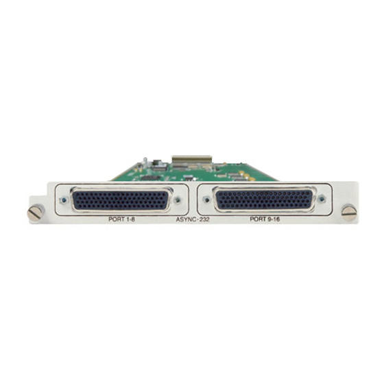
Page 19: Physical Description
The Video Module (see Figure 1-2) plugs into any available option slot in the rear of the ATLAS 800 Series chassis. Figure 1-2. Video Module The label under each 68-pin connector refers to the port on the Video Module. 61200773L1-1A ATLAS 800 Series Video Module User Manual... - Page 20 Chapter 1. Introduction ATLAS 800 Series Video Module User Manual 61200773L1-1A...
-
Page 21: Chapter 2 Installation
Carefully unpack and inspect the Video Module for shipping damages. If you suspect damage occurred during shipping, file a claim immediately with the carrier and then contact ADTRAN Technical Support (see the front pages of this manual for pertinent information). If possible, keep the original shipping container for returning the Video Module for repair or for verification of shipping damage. -
Page 22: Installing The Video Module
Secure the thumbscrews at both edges of the module. Connect the cables to the associated device(s). Complete installation of remaining modules and Base Unit as specified in the Installation chapter of the ATLAS 800 Series User Manual. To ensure that the thumbscrews are securely fastened, use a screwdriver to tighten them. -
Page 23: Wiring
Transmitted data (TD-B) from DTE TX clock (TC-A) to DTE TX clock (TC-B) to DTE External TX clock (ETC-A) from DTE External TX clock (ETC-B) from DTE — Test mode (TM) to DTE - (Not Supported) 61200773L1-1A ATLAS 800 Series Video Module User Manual... -
Page 24: Table 2-2. Eia-530 Connector Pinout
Carrier Detect (A) DTE Ready (A) Received Clock (B) Not Used Carrier Detect (B) DCE Ready (B) Ext. Transmit Clock (B) DTE Ready (B) Transmit Clock (B) Ext. Transmit Clock (A) Not Used ATLAS 800 Series Video Module User Manual 61200773L1-1A... -
Page 25: Table 2-3. Rs-449 Pinout
Remote Loopback - (Not Supported) Not Used Ring Indicator Not Used Not Used Not Used Ext. Transmit Clock (A) Ext. Transmit Clock (B) Test Mode - (Not Supported) Not Used Not Used 61200773L1-1A ATLAS 800 Series Video Module User Manual... -
Page 26: Power Up And Initialization
POWER UP AND INITIALIZATION The Video Module requires no initialization input during the power-up sequence, as described in the ATLAS 800 Series User Manuals. Any previously configured set- ting for the Video Module is automatically restored upon power-up. Failed Self-Test If the Video Module fails self-test, a message will be displayed in the terminal menu self-test log during power-up. -
Page 27: Chapter 3 Operation
TERMINAL MENU STRUCTURE ATLAS 800 Series uses a hierarchical menu structure to provide access to all of its features. The top-most menu level leads to submenus which are grouped by func- tionality. All menu items display in the terminal window. To access the Video Mod- ule, activate the M menu. -
Page 28: Modules
Figure 3-1. Modules Menu Read security: 5 Displays the number of the available slots in the ATLAS 800 Series chassis. Slot 0 refers to the ATLAS 800 Series unit. This field is read-only. Write security: 3; Read security: 5 Displays the type of module actually installed in the slot or the type of module you plan to install in the slot. -
Page 29: Alarm
O for the TATE NLINE ATLAS 800 Series unit to use the module for any data bandwidth. TATUS This read-only field provides status information on the Video Module. The follow- ing messages may display: The module is enabled, and is responding to the system controller’s status polls. -
Page 30: Modules/Menu
A rate mismatch exists between the DTE clock and the network-side clock (as set by DS0 assignment). The Video Module DTE port is not able to lock onto the clock provided by the net- work interface. ATLAS 800 Series Video Module User Manual 61200773L1-1A... -
Page 31: Dte Status
Displays the data rate at which each Video Module DTE port is currently operating. A port’s data rate is determined by the number of B channels assigned to it and the rate per channel associated with the active call. 61200773L1-1A ATLAS 800 Series Video Module User Manual... -
Page 32: Pll/Fifo
Accepts any alpha-numeric name up to 16 characters long, to uniquely identify each DTE port on the Video Module. Controls the clock used by the ATLAS 800 Series to accept the transmit (TX) data from the DTE. This is usually set to N . -
Page 33: Test
When the port detects an uninterrupted string of 0s being transmitted for more than one second, setting this parameter to O will cause the ATLAS 800 Series to send 1s toward the network. These options initiate different types of tests and display test results. -
Page 34: Dte Interface
DTE I NTERFACE Configures the DTE port interface type. The following options are available: The ATLAS 800 Series will automatically detect the interface type. The cable must be connected before the interface can be determined. EIA-530 Configures the interface for EIA-530 use. -
Page 35: Current Dte Type
, a submenu of the ATLAS 800 Series main menu item T , exe- ELFTEST cutes both the Video Module internal test and the ATLAS 800 Series internal test. For additional information on R , see the ATLAS 800 Series User Man- ELFTEST ual. - Page 36 Chapter 3. Operation ATLAS 800 Series Video Module User Manual 61200773L1-1A...
-
Page 37: Appendix A Dial Plan Interface Configuration
The following section describes the configuration options available for the ATLAS 800 Series Video Module. To access these options, select D from the ATLAS menu. The Video Module is only available for User Term applications Figure A-1. Dial Plan Menus 61200773L1-1A ATLAS 800 Series Video Module User Manual... - Page 38 Appendix A. Dial Plan Interface Configuration ATLAS 800 SERIES VIDEO MODULE: USER TERMINATION The ATLAS 800 Series Video Module acts like the network while interfacing to user equipment (video equipment). When you are working in the U section of the D...
- Page 39 BONDING resource to inverse multiplex the multiple switched channels together. EFAULT Write Security: 3; Read Security: 5 Specifies the data rate for single call as either 56 or 64 kbps if not specified in the Smart Dial string. 61200773L1-1A ATLAS 800 Series Video Module User Manual...
- Page 40 If the call is negotiated and the maximum DS0s value is not acceptable to the answering equipment, the call will be disconnected. Any value other than 1 requires a BONDING resource to inverse multiplex the multiple switched channels together. ATLAS 800 Series Video Module User Manual 61200773L1-1A...
- Page 41 Write Security: 3; Read Security: 5 Enter the numbers to dial using the RS-366 Type II dialing interface in the stored UMBERS numbers list. This list can contain up to 10 stored numbers. Entry number (1-10). 61200773L1-1A ATLAS 800 Series Video Module User Manual...
- Page 42 If the call is negotiated and the maximum DS0s value is not acceptable to the answering equipment, the call will be disconnected. Any value other than 1 requires a BONDING resource to inverse multiplex the multiple switched channels together. ATLAS 800 Series Video Module User Manual 61200773L1-1A...
- Page 43 If the call is negotiated and the minimum DS0s value is not met, the call will be disconnected. Any value other than 1 requires a BONDING resource to inverse multiplex the multiple switched channels together. 61200773L1-1A ATLAS 800 Series Video Module User Manual...
- Page 44 If the call is negotiated and the maximum DS0s value is not acceptable to the answering equipment, the call will be disconnected. Any value other than 1 requires a BONDING resource to inverse multiplex the multiple switched channels together. ATLAS 800 Series Video Module User Manual 61200773L1-1A...
-
Page 45: Appendix B Smart Dial String Formats
BONDING 384k using 64K call type (6x64k) 7082906055#4#6#0 BONDING 336k using 56K call type (6x56k) 7082906055#3#6#0 BONDING 256k using 64K call type (4x64k) 7082906055#4#4#0 BONDING 256k using 64k call type (4x64k) 7082906055#4#4#5 with Source ID 5 61200773L1-1A ATLAS 800 Series Video Module User Manual... - Page 46 384k (6x64k) on Source ID=0, only the #3 and #8 suf- fixes are required to change the call type to 448k. The dial string 7082906055#3#8 is the same as 7082906055#3#8#0. ATLAS 800 Series Video Module User Manual 61200773L1-1A...
-
Page 47: Appendix C Video Module Menu Tree
Loopback Local Loopback (shortcut) Loopback Status 511 Results Sync Inject AUTO DTE Interface DTE Interface Mode EIA-530 V.35 Current DTE Type RS-449 Loopback Figure C-1. ATLAS 800 Series Video Module Menu Tree 61200773L1-1A ATLAS 800 Series Video Module User Manual... - Page 48 Appendix C. Video Module Menu Tree ATLAS 800 Series Video Module User Manual 61200773L1-1A...
-
Page 49: Index
Min Incoming DS0s ....40 Redial Number ......41 61200773L1-1A ATLAS 800 Series Video Module User Manual... - Page 50 ........23 ATLAS 800 Series Video Module User Manual...
Need help?
Do you have a question about the ATLAS 800 Series and is the answer not in the manual?
Questions and answers