Sign In
Upload
Manuals
Brands
ADTRAN Manuals
Network Card
ATLAS 800 Series Module QUAD E1
ADTRAN ATLAS 800 Series Module QUAD E1 Manuals
Manuals and User Guides for ADTRAN ATLAS 800 Series Module QUAD E1. We have
4
ADTRAN ATLAS 800 Series Module QUAD E1 manuals available for free PDF download: System Manual, User Manual, Specification Sheet
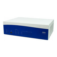
ADTRAN ATLAS 800 Series Module QUAD E1 System Manual (381 pages)
ATLAS 800 SERIES
Brand:
ADTRAN
| Category:
Network Hardware
| Size: 5 MB
Table of Contents
Table of Contents
13
About this Manual
2
Revision History
3
Safety Instructions
4
L1-1C © 2004 ADTRAN, Inc
6
L1-1C © 2004 ADTRAN, Inc
7
Product Registration
10
Product Warranty
10
Table of Contents
13
ATLAS 830 Description
16
Equipment Dimensions
16
Power Requirements (AC System)
16
Power Requirements (DC System)
16
ATLAS 830 Front Panel
16
Figure 1. ATLAS 830 Front Panel Layout
16
ACO Switch
17
CRAFT Port
17
Front Panel Leds
17
Pinout 1. ATLAS 830 CRAFT Port (DB-9, Female)
17
Section 1 Engineering Guidelines
17
Table 1. ATLAS 830 Front Panel Leds' Purpose
17
Table 2. ATLAS 830 LED Descriptions
19
ATLAS 830 Rear Panel
20
Admin Port
21
Pinout 2. ATLAS 830 Admin Port (DB-9, Female)
21
Figure 2. ATLAS 830 Rear Panel
21
10/100Baset Connection
22
Alarm Relay Connection
22
Mon
22
T1/PRI Connections
22
Pinout 3. ATLAS 830 Ethernet (RJ-45)
22
Pinout 4. ATLAS 830 Alarm Relay Connector
22
ATLAS 830 At-A-Glance Specifications
23
Pinout 5. ATLAS 830 T1/PRI
23
Table 3. ATLAS 830 Specifications
23
ATLAS 890 Description
26
Equipment Dimensions
26
Power Requirements (AC System)
26
Power Requirements (DC System)
26
ATLAS 890 Front Panel
27
ACO Switch
27
Figure 3. ATLAS 890 Front Panel Layout
27
CRAFT Port
28
Front Panel Leds
28
Pinout 6. ATLAS 890 CRAFT Port (RJ-48C)
28
Table 4. ATLAS 890 Front Panel Leds' Purpose
28
Table 5. ATLAS 890 LED Description
29
ATLAS 890 Rear Panel
31
Admin in Port
31
Figure 4. ATLAS 890 Rear Panel
31
10/100Baset Connection
32
Pinout 7. ATLAS 890 Admin in (RJ-48C)
32
Pinout 8. ATLAS 890 Ethernet (RJ-48C)
32
Alarm Relay Connection
33
External Input Connection
33
Pinout 9. ATLAS 890 Alarm Relay Connector
33
Pinout 10. ATLAS 890 External Relay Monitor Connector
33
ATLAS 890 At-A-Glance Specifications
34
Table 6. ATLAS 890 Specifications
34
Option Module Pinouts
36
Quad T1/PRI Option Module
36
Pinout 11. Quad T1/PRI Module (USOC RJ-48C)
36
Quad E1/PRA Option Module
37
Pinout 12. Quad E1/PRA Module (DB-15)
37
Pinout 13. Quad E1/PRA Module (DB-62)
37
Quad Nx 56/64 Option Module
38
Pinout 14. Quad Nx 56/64 Module (V.35 Winchester)
38
Pinout 15. Quad Nx 56/64 Module (DB-78)
38
Quad USSI Option Module
40
Pinout 16. Quad USSI Module (DB-78)
40
Pinout 17. Quad USSI Module (EIA-530)
41
Pinout 18. Quad USSI Module (RS-449/V.36)
41
Pinout 19. Quad USSI Module (RS-232)
42
Pinout 20. Quad USSI Module (CCITT X.21 V.11)
42
Octal BRI ISDN (U-Interface) Option Module
43
Octal BRI ISDN (S/T Interface) Option Module
43
Pinout 21. Octal BRI (U-Interface) Module (RJ-45)
43
Pinout 22. Octal BRI (S/T Interface) Module (RJ-45)
43
Async-232 Option Module
44
T3 Option Module
44
Pinout 23. Async-232 Option Module (DB-25)
44
Pinout 24. T3 Module (BNC Pair, Female)
44
T3 Drop and Insert Option Module
45
Dual Video Option Module
45
Pinout 25. T3 Drop and Insert Module (BNC Pair, Female)
45
Pinout 26. Dual Video Module (RS-366, DB-25)
45
Pinout 27. Dual Video Module (V.35 Winchester)
46
Pinout 28. Dual Video Module (EIA-530)
47
Pinout 29. Dual Video Module (RS-449)
47
Nxt1 HSSI/V.35 Option Module
48
Pinout 30. Nxt1 HSSI/V.35 Module (RJ-48C)
48
Pinout 31. Nxt1 HSSI/V.35 Module (50-Pin SCSI-II and V.35 Winchester)
48
Octal FXS Option Module
49
Pinout 32. Octal FXS Module (8-Pin Modular)
49
Section 2 System Description
50
System Overview
51
Table of Contents
51
Features and Benefits
51
Configuration and Management
51
Software Upgradeable
51
Signaling Support
52
ISDN Switch Types
52
Dedicated Connection Maps
52
Switched Connection Maps
52
Testing
52
Performance Monitoring
52
Frame Relay
52
PPP Switching
53
Option Modules Overview
53
ATLAS 890 System Controller Module (P/N 1200322L1)
54
Quad T1/PRI Option Module (P/N 1200185L3)
54
Quad E1/PRA Option Module (P/N 1200264L1)
54
Quad Nx 56/64 Option Module (P/N 1200184L1)
54
Quad USSI Option Module (P/N 4200261Lx)
54
Octal Basic Rate ISDN (U-Interface) Option Module (1200186L2)
54
Octal Basic Rate ISDN (S/T Interface) Option Module (1200343L1)
54
T3 Option Module (P/N 1200223L1)
55
T3 Option Module with Drop and Insert Interface (P/N 1200225L1)
55
Dual Video Option Module (P/N 4200773Lx)
55
Nxt1 HSSI/V.35 Option Module (1200771L1)
55
Octal FXS Option Module (P/N 1200338L1)
55
Channel Voice Compression Resource Modules (P/N 1200221Lx)
55
Nx 56/64 Bonding Resource Module (P/N 1200262L1)
55
HDLC Resource Module (P/N 1200222L1)
56
Modem-16 Resource Module (P/N 1200181L1)
56
Modem-24 Resource Module (P/N 1200782L1)
56
Async-232 Option Module (P/N 1200182L1)
56
Section 3 Network Turnup Procedures
57
Provides Step-By-Step Instructions for Installing and Powering up the ATLAS
57
Introduction
58
Tools Required
58
Unpacking and Inspecting the System
58
Contents of ADTRAN Shipment
58
Grounding Instructions
59
Supplying Power to the Unit
60
AC-Powered Systems
60
DC-Powered Systems
60
Mounting Options
61
Installing Network and Option Modules
62
Option Slots Numbering
62
Modules Installation Instructions
63
Modules Shipping Contents
63
Table of Contents
58
Section 4 User Interface Guide
66
Provides Detailed Descriptions of All Menu Options and Configuration Parameters for
66
The ATLAS 800 Series System
66
Table of Contents
68
Navigating the Terminal Menus
68
Terminal Menu Window
68
Navigating Using the Keyboard Keys
70
Getting Help
72
Terminal Menus and System Control
73
Selecting the Appropriate Menu
73
Security Levels
73
Firmware Revision
74
System Contact
74
System Info Menu Descriptions
74
System Location
74
System Name
74
Boot Rom Rev
75
Current Time/Date (24Hr)
75
Installed Memory
75
Serial Number
75
Startup Mode
75
System Uptime
75
Event Log
76
System Status Menu Descriptions
76
Clear System Event Log
77
Resource Usage
79
System Timing Source
79
Trunk Usage
81
Redundancy (Atlas)
82
Primary Timing Source
83
Adlp Address
83
Backup Timing Source
83
Session Timeout
83
System Config Menu Descriptions
83
Max Telnet Sessions
84
Event Logging
89
Syslog Setup
89
Real Time Clock
90
Access Passwords
90
Bonding Config
91
Alarm Relay Reset
92
Alarm Relay State
92
Alarm Relay Threshold
92
Ext. Input Threshold (Atlas)
92
Ext. Input Alarm (Atlas)
93
System Utility Menu Descriptions
94
Update Firmware
94
Update Status
95
Config Transfer
96
System Selftest
97
System Utilization
97
Atel Client
99
Alarm Relay Test (Atlas)
101
Force Controller Switch (Atlas)
101
Reboot System
101
Modules Menu Descriptions
102
Quad T1/PRI Option Module
105
Ds0 Alarms
107
Sig Status
107
Quad E1/PRA Option Module
112
Ts0 Alarms
114
Ts0 Status
114
Quad Nx56/64 Option Module
118
Data Rate
120
USSI Option Module
125
Octal BRI U Option Module
134
Octal BRI S/T Option Module
137
T3 Option Module
140
Ds1 Performance 15Min
147
T3 D&I Option Module
150
Mux Configuration
151
Ds1 Performance 15 Min
158
Dual Video Option Module
161
Nxt1 HSSI Option Module
167
Octal FXS Option Module
176
VCOM Option Module
180
Nx 56/64 Bonding Resource Module
187
HDLC Resource Module
190
Modem-16 Resource Module
192
Modem-24 Resource Module
203
Async-232 Option Module
210
Packet Manager
219
Packet Endpnts
219
Packet Cncts
234
Cncts Sort
235
Frame Relay Iq
235
Arp Cache
241
Udp Relay
251
Dedicated Maps
253
Dial Plan
267
Section 5 Detail Level Procedures (Dlp)
316
Provides the Detailed Instruction for Performing Various Unit Functions such as
316
Upgrading Firmware
316
DLP-1 Connecting the Terminal or PC to the ADMIN or CRAFT Port
317
DLP-2 System Login and Menu Access
319
DLP-3 Setting IP Parameters for the ATLAS 800 Series System
322
DLP-4 Verifying Communications over an IP LAN
324
DLP-5 User Access and Password Security Levels
327
DLP-6 Updating ATLAS Firmware Using TFTP
329
DLP-7 Updating ATLAS Firmware Using XMODEM
332
DLP-8 Saving the Current Configuration Using TFTP
335
DLP-9 Connecting the ATLAS to an External Modem
337
Using the Event Log (Syslog)
340
DLP-11 Connecting the Alarm Contacts
344
DLP-12 Connecting to the ATLAS 890 External Input
347
DLP-13 Using the Alarm Connections and ACO Button
350
Section 6 System Event Log
351
Section 7 ADTRAN Utilities
367
Provides Instructions for Configuring and Using the ADTRAN Utilities (Telnet
367
VT100, Syslog, and TFTP
367
Telnet Utility
368
Edit Menu
370
Options Menu
370
Help Menu
371
Vt100 Utility
372
Port Menu
373
Tftp Server
374
Server Menu
375
Print Log
375
Index
377
Advertisement
ADTRAN ATLAS 800 Series Module QUAD E1 User Manual (190 pages)
Brand:
ADTRAN
| Category:
Network Hardware
| Size: 1 MB
Table of Contents
Table of Contents
13
List of Figures
19
Product Overview
23
Figure 1-1. Digital Access Cross-Connect System (DACS)
25
Figure 1-2. T1 Bandwidth Management
25
Figure 1-3. WAN Overbooking
26
ATLAS_800 Base Unit
29
Check the Power Connection
29
Contents of ADTRAN Shipments
29
Inspect the ADTRAN Shipment
29
Installing the ATLAS 800
29
AC Powered Unit
30
DC Powered Unit
30
Grounding Instructions
30
Review the Rear Panel Design
31
Connection
32
Control/Chain in Port
32
Figure 2-2. DC Powered ATLAS 800 Rear Panel
32
Connection
33
Control/Chain out Port
33
Table 2-1. Control/Chain in Pinout
33
Table 2-2. Control/Chain out Pinout
33
10Baset Ethernet Connection
34
Connection
34
Network Connection
34
Table 2-3. Network Pinout
34
Install any Option Modules
35
Mon
35
Option Slots
35
Table 2-4. Ethernet 10Baset Pinout
35
Power-Up
36
Figure 3-1. Front Panel LCD
37
Using the Front Panel
37
Figure 3-2. Example of Basic Front Panel Menu Navigation
38
Using the Terminal Menu
38
Using Telnet
39
Starting a Telnet Session
40
Using VT-100 Terminal Emulation
40
Using T-Watch PRO
41
Chapter 4 Using the Front Panel
44
Table 4-1. ATLAS 800 Front Panel Description
44
Table 4-2. LED Descriptions
45
Operation Keys
46
Front Panel Menu Structure
46
Figure 4-2. Front Panel LCD
46
Table 4-3. Operation Keys
46
Front Panel Main Menu
48
Figure 4-3. Front Panel Menu Tree
48
Status
49
S0 System
49
S1-S8
49
Config
49
S1-S8
51
Util
51
Time/Date
51
Software Rev
51
Selftest
52
Set Passcode
53
Password Reset
53
ALRM Menu
53
Active Alarms
53
View History
54
Clear History
54
Chapter 5 Navigating the Terminal Menu
55
Terminal Menu Window
55
Menu Path
55
Figure 5-1. Top-Level Terminal Menu Window
55
Window Panes
56
Window Pane Navigation
56
Right Window Pane Notation
56
Additional Terminal Menu Window Features
57
Navigating Using the Keyboard Keys
57
Moving through the Menus
57
Session Management Keystrokes
58
Configuration Keystrokes
58
Getting Help
59
Selecting the Appropriate Menu
61
Security Levels
61
System Info
62
Figure 6-1. System Information Menu
62
Table 6-1. Password Security Levels
62
System Name
63
System Location
63
System Contact
63
Firmware Revision
63
System Uptime
63
Startup Mode
63
Installed Memory
63
Serial Number
63
Boot ROM Rev
63
System Status
63
Event Log
64
Clear System Event Log
64
Figure 6-2. System Status Menu
64
Ethernet Port
65
Clear System LED
65
System Alarms
65
System Timing Source
65
Resource Usage
65
Chain Port Signal Leads
66
Chain Port Tx Bytes
66
Chain Port Rx Bytes
66
Chain Port Overrun Errs
66
Chain Port Framing Errs
66
Clear Chain Port Countrs
66
System Config
66
Primary Timing Source
67
Backup Timing Source
67
ADLP Address
67
Session Timeout
67
Max Telnet Sessions
67
Figure 6-3. System Configuration Menu
67
Ethernet Port
68
Chain Port
68
System Event Logging
70
Syslog Setup
70
Real Time Clock
70
Access Passwords
71
System Utility
72
Update Firmware
72
Figure 6-4. System Utility Menu
72
Update Status
75
Config Transfer
75
System Utilization
76
System Selftest
76
Ping
77
Figure 6-5. View Self-Test Log
77
Reboot System
78
Factory Default System
78
Chapter 7 Modules Terminal Menu
79
Menus
79
Submenus
79
Modules
79
Slt
79
Type
79
Figure 7-1. Modules Menu
79
Menu
80
Alarm
80
Test
80
State
80
Status
81
Rev
81
Modules (T1/PRI) Menu
81
Chapter 8 Dedicated Maps Terminal Menu
85
Overview
85
Figure 8-1. Dedicated Maps Menu Tree
85
Activate Map
86
Auto
86
Maps 1-5
86
Current Map
86
Create / Edit Maps
86
Map Name
86
Sort TO/FROM
86
Connects
86
Activate Time
89
Enbl Day
89
Figure 8-2. Trunk Conditioning
89
Designing the Dedicated Map for Example 2
90
Figure 8-3. Dedicated Map Overview Example
90
Table 8-1. Connections and Ports
90
Configuring the Ports for Example 2
91
Figure 8-4. Slot 0 Module Configuration Menu
91
Figure 8-5. Completed Dedicated Map
93
Chapter 9 Dial Plan Terminal Menu
95
Overview
95
Figure 9-1. Dial Plan Menu
95
Network Term
96
Slot
96
Port
96
Figure 9-2. Dial Plan Menu Tree
96
Sig
97
Out#Accept
97
Out#Rej
98
Ifce Config
99
User Term
99
Slot/Svc
99
Port/Link
99
Sig
99
In#Accept
99
Out#Rej
101
Ifce Config
101
Global Param
101
End of Number Timeout
101
Area Code
101
Nbr Complete Templates
102
Number Type Templates
102
Automatic Routeback Rejection
103
Quad T1/PRI Interface Configuration
103
Network Termination/Pri
103
Figure 9-3. Network Term PRI/ Ifce Config Menu Tree
104
Network Termination/Rbs
107
Figure 9-4. Network Term RBS / Ifce Config Menu Tree
107
User Termination/Pri
109
Figure 9-5. User Term PRI / Ifce Config Menu Tree
109
User Termination/Rbs
111
Figure 9-6. User Term RBS / Ifce Config Menu Tree
111
Creating Dial Plans-Examples
113
Understanding Dial Plan Configurations
114
Figure 9-7. PSTN Connection
114
Figure 9-8. Point-To-Point
114
Figure 9-9. Remote Access and Video Conferencing Setup
115
Table 9-1. Network and Attached Equipment Provisioning
116
Table 9-2. Network Terminations
117
Table 9-3. User Terminations
118
Figure 9-10. Completed Network Map
120
Figure 9-11. Completed User Map
121
Chapter 10 Updating Firmware
123
Overview
123
XMODEM Firmware Updates
123
Updating Firmware Using XMODEM
124
Figure 10-1. Update Firmware Menu Interface
125
TFTP Firmware Updates
126
Updating Firmware Using TFTP
126
Table 10-1. TFTP Upload Messages
127
Figure 10-2. Update Firmware Menu Interface
128
Chapter 11 SNMP Management
129
Snmp
129
Basic Components
129
Network Manager
129
Agent
129
Mib
129
SNMP Traps
130
Trap Destination List
130
Configuring a Trap Destination List Via Terminal Menu
130
Filtering (Disabling) Traps
130
Table 11-1. Trap Destination List
130
Standard Traps
131
DS1 Traps
131
DS1 Alarm Traps
131
Table 11-2. Standard Traps
131
DS1 Alert Traps
132
Table 11-3. DS1 SNMP Traps
132
Table 11-4. DS1 Current Alert SNMP Traps
132
Table 11-5. Total Alert Traps
133
Chapter 12 ADTRAN Utilities
135
Overview
135
Syslog Host Daemon
135
Syslog GUI
136
Monitor
136
Figure 12-1. ATLAS Syslog Host GUI
136
Menu Bar
137
File
137
Display
137
Figure 12-2. Syslog Menu Tree for the Menu Bar
137
Log Files
138
Erase Log Files
138
Define RED Events
138
Properties
138
Clear Red Events
138
Help
138
Telnet Utility
138
Session Menu
139
Connect
139
Figure 12-3. Telnet Menu Tree
139
Disconnect
140
Transfer Cfg
140
Exit
140
Edit Menu
140
Options Menu
140
Colors
140
Local Echo
141
Autorepeat
141
Capture Menu
141
File
141
Buffer Size
141
Save Buffer as
141
Screen Capture
141
Help Menu
141
Contents
141
IP Status
141
Session Menu
142
Connect
142
Disconnect
142
File Transfer
142
Figure 12-4. VT-100 Menu Tree
142
Edit Menu
143
Port Menu
143
Options Menu
143
Refresh Screen
143
Connect
143
Colors
143
Local Echo
143
Autorepeat
143
Capture Menu
143
Help Menu
143
Enable
144
Disable
144
Abort
144
Exit
144
Print Log
144
To Clipboard
144
To Printer
144
Clear Log
144
Help
144
Contents
144
Status Field
145
Meter Field
145
Log Field
145
Saving the Current Configuration to a TFTP Server
146
Successful Transfer
146
Unsuccessful Transfer
147
Retrieving the Configuration from a TFTP Server
147
Appendix A System Event Logging
150
Table A-1. Source: System
150
Table A-2. Source: Switchboard
151
Table A-3. Source
152
Table A-4. Source Time
153
Table A-5. Source: Ethernet
154
Table A-6. Source: ISDN
155
Table A-7. ISDN Cause Codes
158
Table A-8. Cause Code Log Entries
160
Table A-9. Source: ISDN L2 Messages
160
Table A-10. Source: ISDN Call Control Messages
160
Table A-11. Source: ISDN Information Elements
161
Appendix B Troubleshooting
163
Appendix C Warranty and Technical Support Information
167
Appendix D Acronyms and Abbreviations
169
Appendix E Glossary
171
Index
177
ADTRAN ATLAS 800 Series Module QUAD E1 User Manual (50 pages)
DUAL VIDEO MODULE
Brand:
ADTRAN
| Category:
Control Unit
| Size: 0 MB
Table of Contents
Table of Contents
11
Chapter 1 Introduction
17
Video Module Overview
17
Functional Description
17
Figure 1-1. Video Module System
17
Features
18
Video Module Specifications
18
Physical Description
19
Figure 1-2. Video Module
19
Chapter 2 Installation
21
Before Installing the Video Module
21
Shipping Contents
21
Installing the Video Module
22
Figure 2-1. Installing the Video Module
22
Wiring
23
Table 2-1. V.35 Winchester Pinout
23
Table 2-2. EIA-530 Connector Pinout
24
Table 2-3. RS-449 Pinout
25
Power up and Initialization
26
Failed Self-Test
26
Operation Alarms
26
Table 2-4. RS-366 Connector Pinout
26
Chapter 3 Operation
27
Overview
27
Terminal Menu Structure
27
Modules
28
Slt
28
Type
28
Menu
28
Figure 3-1. Modules Menu
28
Alarm
29
Test
29
State
29
Status
29
Online
29
No Response
29
Empty
29
Offline
29
Offline/No Response
29
Rev
29
Modules/Menu
30
Video Menus
30
Info
30
Alarm Status
30
Figure 3-2. Video Module Menu Options
30
DTE Status
31
Data Rate
31
Pll/Fifo
32
Configuration
32
Test
33
Table 3-1. DTR Descriptions
33
DTE Interface
34
Current DTE Type
35
Module Alarms
35
Test Activity
35
ATLAS Features Used with Video Module Options
35
Factory Restore
35
Run Selftest
35
Appendix A Dial Plan Interface Configuration
37
Figure A-1. Dial Plan Menus
37
Appendix B Smart Dial String Formats
45
Appendix C Video Module Menu Tree
47
Figure C-1. ATLAS 800 Series Video Module Menu Tree
47
Index
49
Advertisement
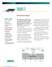
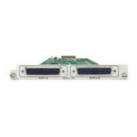
ADTRAN ATLAS 800 Series Module QUAD E1 Specification Sheet (2 pages)
ADTRAN ATLAS 800 Series Module Specification SHeet
Brand:
ADTRAN
| Category:
Network Card
| Size: 0 MB
Advertisement
Related Products
ADTRAN ATLAS 550
ADTRAN AHDSL2
ADTRAN AHT1U
ADTRAN ATLAS 810 Plus
ADTRAN Atlas 830
ADTRAN ATLAS 890
ADTRAN Atlas 800 Plus
ADTRAN ATLAS
ADTRAN AOS R10.1.0
ADTRAN Async-232
ADTRAN Categories
Network Hardware
Network Router
Switch
Gateway
Control Unit
More ADTRAN Manuals
Login
Sign In
OR
Sign in with Facebook
Sign in with Google
Upload manual
Upload from disk
Upload from URL