
Subscribe to Our Youtube Channel
Related Manuals for Omron M1 Series


Summary of Contents for Omron M1 Series
- Page 1 Multi-function Compact Inverter M1 Series EtherCAT Type User’s Manual 3G3M1-A££££-ECT I670-E1-02...
- Page 2 Moreover, because OMRON is constantly striving to improve its high-quality products, the infor- mation contained in this manual is subject to change without notice. 3. Every precaution has been taken in the preparation of this manual. Nevertheless, OMRON as- sumes no responsibility for errors or omissions.
-
Page 3: Intended Readers
Before using the inverter, read this manual and gain a full understanding of the information provided herein. After you finished reading this manual, keep it in a convenient place so that it can be referenced at any time. Make sure this manual is delivered to the end user. M1 Series EtherCAT Type User’s Manual (I670) -
Page 4: Manual Configuration
Appendix This section provides a description of profiles and a list of objects for controlling the inverter, and provides informa- tion on Sysmac error status codes, derating, capacitor life curve and inverter selection. M1 Series EtherCAT Type User’s Manual (I670) -
Page 5: Manual Structure
Precautions on what to do and what not to do to ensure safe usage of the product. Precautions for Correct Use Precautions on what to do and what not to do to ensure proper operation and performance. M1 Series EtherCAT Type User’s Manual (I670) - Page 6 Manual Structure Additional Information Additional information to read as required. This information is provided to increase understanding or make operation easier. References are provided to more detailed or related information. M1 Series EtherCAT Type User’s Manual (I670)
-
Page 7: Sections In This Manual
Sections in this Manual Sections in this Manual Overview Maintenance and Inspection Design Appendix EtherCAT Communications Inverter Control Operation and Test Run Basic Settings Vector Control and Applied Functions Other Functions Troubleshooting M1 Series EtherCAT Type User’s Manual (I670) -
Page 8: Table Of Contents
Revision History..................... 31 Section 1 Overview Overview of Functions ......................1-2 1-1-1 Features of 3G3M1 Series Inverter .....................1-2 1-1-2 Classes of 3G3M1 Series Inverter ....................1-3 1-1-3 Compliance with International Standards..................1-5 Appearance and Part Names ....................1-6 M1 Series EtherCAT Type User’s Manual (I670) - Page 9 Description of Operation ......................3-16 3-9-2 Wiring ............................3-16 3-9-3 Procedure of Checking Operation .....................3-17 3-9-4 Slave Communications Statuses When Cable Redundancy Function Is Used ......3-18 3-9-5 Relation between the Network Configuration Information and the Actual Configuration ..3-19 M1 Series EtherCAT Type User’s Manual (I670)
- Page 10 Acceleration/Deceleration Time Settings ................6-33 6-6-1 Acceleration/Deceleration Time Setting ..................6-33 6-6-2 Acceleration/Deceleration Pattern.....................6-34 6-6-3 Acceleration/Deceleration Stop Function ..................6-36 6-6-4 2-step Acceleration/Deceleration Function ................6-37 Stop Method Settings ......................6-41 6-7-1 Stop Selection ...........................6-41 Reset .............................6-43 6-8-1 Reset Function ..........................6-43 M1 Series EtherCAT Type User’s Manual (I670)
- Page 11 7-7-16 Position Store Selection at Power OFF..................7-61 7-7-17 Excessive Positional Deviation ....................7-61 7-7-18 Touch Probe (Latch) Function ....................7-62 Motor tuning .........................7-65 7-8-1 Motor Off-line Auto-tuning ......................7-65 7-8-2 Online Tuning ..........................7-71 Brake control function......................7-72 M1 Series EtherCAT Type User’s Manual (I670)
- Page 12 Capacitor Life Warning Signal (WAC) ..................8-85 8-8-11 Braking Transistor Broken (DBAL) ....................8-87 8-8-12 Cooling FAN Control Method Selection..................8-88 8-8-13 Cooling Fan Life Warning Signal (WAF)..................8-88 8-8-14 Life Alarm (LIFE) ........................8-88 8-8-15 Starting Contact Signal (FR) .....................8-90 M1 Series EtherCAT Type User’s Manual (I670)
- Page 13 10-1-3 Periodic Inspection ........................10-2 10-1-4 Daily/Periodic Inspection Items ....................10-3 10-1-5 Megger Test ..........................10-6 10-1-6 Withstand Voltage Test......................10-7 10-1-7 I/O Voltage/Current/Electric Power Measurement Method ............10-7 10-1-8 Method for Ring Disconnection Maintenance and Inspection ...........10-9 M1 Series EtherCAT Type User’s Manual (I670)
- Page 14 Smoothing Capacitor Life Curve ..................A-291 Life Alarm Output......................A-294 A-10 Overview of Inverter Selection ..................A-295 A-10-1 Motor Capacity Selection ....................... A-295 A-10-2 Inverter Capacity Selection ....................A-298 A-10-3 Overview of Braking Resistor Selection ................. A-299 M1 Series EtherCAT Type User’s Manual (I670)
-
Page 15: Terms And Conditions Agreement
Omron’s exclusive warranty is that the Products will be free from defects in materials and work- manship for a period of twelve months from the date of sale by Omron (or such other period ex- pressed in writing by Omron). Omron disclaims all other warranties, express or implied. -
Page 16: Application Considerations
WAY CONNECTED WITH THE PRODUCTS, WHETHER SUCH CLAIM IS BASED IN CONTRACT, WARRANTY, NEGLIGENCE OR STRICT LIABILITY. Further, in no event shall liability of Omron Companies exceed the individual price of the Product on which liability is asserted. Application Considerations... -
Page 17: Statement Of Security Responsibilities For Assumed Use Cases And Against Threats
Product. Errors and Omissions Information presented by Omron Companies has been checked and is believed to be accurate; how- ever, no responsibility is assumed for clerical, typographical or proofreading errors or omissions. Statement of security responsibilities for assumed use cases and... -
Page 18: Safety Precautions
The symbol shown to the left indicates "Caution against electric shock." This symbol indicates caution and warning. The specific instruction is indicated using an illustration or text inside or near The symbol shown to the left indicates “Caution against fire.” M1 Series EtherCAT Type User’s Manual (I670) - Page 19 There is a risk of severe injury. Do not enter the operating area during operation. There is a risk of severe injury due to electric shock. Do not perform maintenance while the power supply is ON. M1 Series EtherCAT Type User’s Manual (I670)
- Page 20 Not doing so may result in electric shock or accidents. M1 Series EtherCAT Type User’s Manual (I670)
- Page 21 For safety, equip the inverter with an external protective function. Not doing so may result in fire or accidents. Do not dismantle, repair or modify the product. Doing so may result in injury or electric shock. M1 Series EtherCAT Type User’s Manual (I670)
- Page 22 Checking validity of backups and preparing data for restore in case of falsification and ab- normalities • Safety design, such as emergency shutdown and fail-soft operation in case of data tam- pering and abnormalities M1 Series EtherCAT Type User’s Manual (I670)
- Page 23 When installing the product, use only the specified screws. Not doing so may result in fire or accidents. Do not install or operate an inverter with damaged external or internal components. Doing so may result in injury, fire or accidents. M1 Series EtherCAT Type User’s Manual (I670)
- Page 24 Not doing so may result in injury. UL and cUL compliance is subject to conditions. Strictly observe the conditions listed in the instruction manual or user's manual. Not doing so may result in fire or accidents. M1 Series EtherCAT Type User’s Manual (I670)
-
Page 25: Precautions For Safe Use
• When changing parameters, do not turn OFF the inverter unit until saving is completed. • Even when the inverter power is turned OFF, the counter-electromotive force occurs while the PM motor rotates, which may result in electric shock. M1 Series EtherCAT Type User’s Manual (I670) -
Page 26: Maintenance And Inspection
• The capacitor service life is influenced by the ambient temperature. Refer to “Smoothing Capacitor Life Curve” described in the manual. When a capacitor reaches the end of its service life and does not work as the product, you need to replace the capacitor. M1 Series EtherCAT Type User’s Manual (I670) -
Page 27: Precautions For Correct Use
• This product bears a warning label at the following location to provide handling warnings. • Be sure to follow the instructions. The appearance differs depending on the capacity of the inverter. M1 Series EtherCAT Type User’s Manual (I670) -
Page 28: Warning Description
Precautions for Correct Use Warning Description M1 Series EtherCAT Type User’s Manual (I670) -
Page 29: Regulations And Standards
This product is subject to energy efficiency regulations when it is used in motor systems that are driven by an inverter. For details on inverter efficiency with respect to motor output in accordance with EU efficiency regulations, refer to the following website. https://industrial.omron.eu/en/company-info/environmental/ecodesign-directive M1 Series EtherCAT Type User’s Manual (I670) -
Page 30: Items To Check After Unpacking
Checking the Nameplate The nameplate is affixed to the product. 7.5 kW or lower Inverter model Input specifications Output specifications Unit version 11 kW or higher Inverter model Input specifications Output specifications Unit version M1 Series EtherCAT Type User’s Manual (I670) -
Page 31: Checking The Model
Panel-mounting or closed wall-mounting models Checking the Accessories The instruction manual is the only accessory included in the Multi-function Compact Inverter (3G3M1 Series). Mounting screws and other necessary parts must be provided by the user. M1 Series EtherCAT Type User’s Manual (I670) -
Page 32: Related Manuals
Sysmac Studio Version I589 SYSMAC- To learn about how to Describes how to oper- 1 Drive Functions Oper- SE2□□□ set and adjust the inver- ate Sysmac Studio. ation Manual ter. M1 Series EtherCAT Type User’s Manual (I670) -
Page 33: Revision History
Example I670-E1-01 Man.No. Revision code Revision code Revision date Revised content January 2023 Original production • March 2023 Improved descriptions, etc M1 Series EtherCAT Type User’s Manual (I670) - Page 34 Revision History M1 Series EtherCAT Type User’s Manual (I670)
-
Page 35: Overview
Classes of 3G3M1 Series Inverter ..............1-3 1-1-3 Compliance with International Standards............1-5 Appearance and Part Names ................ 1-6 Specifications ....................1-10 1-3-1 Standard Specifications................. 1-10 1-3-2 EtherCAT Communication Specifications............1-16 1-3-3 External Dimensions ..................1-17 Restrictions ....................1-23 M1 Series EtherCAT Type User’s Manual (I670) -
Page 36: Overview Of Functions
M1 Series EtherCAT Type User’s Manual (I670) -
Page 37: Classes Of 3G3M1 Series Inverter
In the design of Sysmac Studio, attention has been paid to operability so that it has the same look and feel as in OMRON's drive products. This minimizes the need to familiarize yourself with new operations generally required with software tools, and helps improve the efficiency of development when designing and starting up new systems. - Page 38 0.1 kW 0.2 kW 3G3M1-AB001-ECT 0.2 kW 0.4 kW 3G3M1-AB002-ECT 0.4 kW 0.55 kW 3G3M1-AB004-ECT 0.75 kW 1.1 kW 3G3M1-AB007-ECT 1.5 kW 2.0 kW 3G3M1-AB015-ECT 2.2 kW 2.7 kW 3G3M1-AB022-ECT 3.7 kW 3G3M1-AB037-ECT M1 Series EtherCAT Type User’s Manual (I670)
-
Page 39: Compliance With International Standards
Europe and other countries. Standard Applicable standard EN 61800-3:2004/A1:2012 UKCA Functional safety EN 61800-5-2 :2017 STO SIL3 EN/ISO 13849-1:2015, Cat.3 / PLe Electrical safety EN 61800-5-1:2007/A1:2017 UL61800 -5-1, Edition 1, 2012 CSA-C22.2 No.274, 2017 EN 61800-3:2004+A1:2012 M1 Series EtherCAT Type User’s Manual (I670) -
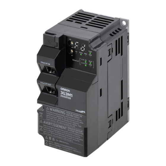
Page 40: Appearance And Part Names
(Factory default) Control circuit terminal block B Auxiliary power supply input terminal Safety input terminal block Safety function selector switch (SW9) Relay output terminal block Control circuit terminal block C Main circuit terminal block M1 Series EtherCAT Type User’s Manual (I670) - Page 41 (3) Cooling Fin (6) Surface cover (Backing plate) Note The single-phase 200-V, 1.5-kW and three-phase 200-V, 1.5-kW models have a cooling fan. The three-phase 400-V, 0.4/0.75/1.5 kW model, however, has no cooling fan. M1 Series EtherCAT Type User’s Manual (I670)
- Page 42 Single-phase 200 V, 3.7kW Three-phase 200 V, 5.5/7.5kW Three-phase 400V, 5.5/7.5kW (1) Cooling Fan Cover (4) Inverter Case (2) Cooling Fan (5) Surface cover (Terminal block cover) (3) Cooling Fin (6) Surface cover (Backing plate) M1 Series EtherCAT Type User’s Manual (I670)
- Page 43 Three-phase 400V, 11/15kW Three-phase 200 V, 18.5/22kW Three-phase 400V, 18.5/22kW (1) Cooling Fan Cover (4) Inverter Case (2) Cooling Fan (5) Surface cover (Terminal block cover) (3) Cooling Fin (6) Surface cover (Backing plate) M1 Series EtherCAT Type User’s Manual (I670)
-
Page 44: Specifications
In calculating the rated capacity, the rated output voltage is assumed to be 200 V or 240 V. A voltage higher than the power supply voltage cannot be output. 1-10 M1 Series EtherCAT Type User’s Manual (I670) - Page 45 23.2 43.8 52.3 60.6 11.3 14.2 16.8 23.2 43.8 52.3 60.6 77.9 Rated output voltage Three-phase 380 to 480V (with AVR) Rated output 11.1 17.5 21.5 28.5 current [A] 14.8 11.1 17.5 1-11 M1 Series EtherCAT Type User’s Manual (I670)
- Page 46 Single-phase 200-V Class HHD: Heavy load, HND: Light load Item Single-phase 200 V Model (3G3M1-AB□□□-ECT) Maxi- 0.75 0.55 applica- ble mo- tor ca- 1 1/2 pacity Rated 200 V output capacity 240V [kVA] 1-12 M1 Series EtherCAT Type User’s Manual (I670)
- Page 47 The maximum applicable motor capacity is 2.2 kW when the input voltage is 220 to 240 V. The maximum applicable motor capacity is 3.0 kW when the input voltage is 220 to 240 V. Common Specifications Item Specifications Open type (IP20) Enclosure rating 1-13 M1 Series EtherCAT Type User’s Manual (I670)
- Page 48 0.75 to 16 kHz (HHD) 0.75 to 10 kHz (HND) • 3G3M1-AB037-ECT 0.75 to 16 kHz (HHD) The carrier frequency automatically drops according to the ambient temperature and output current. (This function can be disabled.) 1-14 M1 Series EtherCAT Type User’s Manual (I670)
- Page 49 PID control, Frequency jump, Analog gain/bias adjustment, S-shape acceler- ation/deceleration, Electronic thermal characteristics/ level adjustment, Restart function, Torque boost function, Fault monitor, Frequency conversion display, USP function, 2nd control function, UP/DOWN, Overcurrent suppression function, etc. 1-15 M1 Series EtherCAT Type User’s Manual (I670)
-
Page 50: Ethercat Communication Specifications
The communications cycle is determined by the cycle time of the master. For the communications response time of the EtherCAT Communication Unit, refer to A-6 Communications Re- sponse Time on page A-286. 1-16 M1 Series EtherCAT Type User’s Manual (I670) -
Page 51: External Dimensions
Note that FreeRun mode in the synchronization mode has a different meaning from free-run stop of an In- verter. 1-3-3 External Dimensions 68 (W) 2xϕ5.2 Power Model W [mm] H [mm] D [mm] supply [mm] Single- 3G3M1-AB001-ECT phase 200 3G3M1-AB002-ECT 3G3M1-AB004-ECT 3G3M1-AB007-ECT Three- 3G3M1-A2001-ECT phase 200 3G3M1-A2002-ECT 3G3M1-A2004-ECT 3G3M1-A2007-ECT 1-17 M1 Series EtherCAT Type User’s Manual (I670) - Page 52 1 Overview 110 (W) 2xϕ5.2 96.5 Power Model W [mm] H [mm] D [mm] D1 [mm] supply Single- 3G3M1-AB015-ECT phase 200 Three- 3G3M1-A2015-ECT phase 200 3G3M1-A2022-ECT Three- 3G3M1-A4004-ECT phase 400 3G3M1-A4007-ECT 3G3M1-A4015-ECT 3G3M1-A4022-ECT 1-18 M1 Series EtherCAT Type User’s Manual (I670)
- Page 53 1 Overview 140 (W) 2xϕ5.2 Power Model W [mm] H [mm] D [mm] D1 [mm] supply Single- 3G3M1-AB022-ECT phase 200 Three- 3G3M1-A2037-ECT phase 200 Three- 3G3M1-A4030-ECT phase 400 3G3M1-A4040-ECT 1-19 M1 Series EtherCAT Type User’s Manual (I670)
- Page 54 1 Overview 180 (W) 2xϕ6 Power Model W [mm] H [mm] D [mm] D1 [mm] supply Single- 3G3M1-AB037-ECT phase 200 Three- 3G3M1-A2055-ECT phase 200 3G3M1-A2075-ECT 87.7 Three- 3G3M1-A4055-ECT phase 400 3G3M1-A4075-ECT 1-20 M1 Series EtherCAT Type User’s Manual (I670)
- Page 55 1 Overview 220 (W) 2xϕ10 Power Model W [mm] H [mm] D [mm] D1 [mm] supply Three- 3G3M1-A2110-ECT phase 200 3G3M1-A2150-ECT Three- 3G3M1-A4110-ECT phase 400 3G3M1-A4150-ECT 1-21 M1 Series EtherCAT Type User’s Manual (I670)
- Page 56 1 Overview 250 (W) 2xϕ10 Power Model W [mm] H [mm] D [mm] D1 [mm] supply Three- 3G3M1-A2185-ECT phase 200 Three- 3G3M1-A4185-ECT phase 400 3G3M1-A4220-ECT 1-22 M1 Series EtherCAT Type User’s Manual (I670)
-
Page 57: Restrictions
Avail- Avail- Avail- Torque bias able able able able Automatic speed control (ASR), Notch Avail- Avail- Avail- Avail- filter able able able able Avail- Avail- Avail- Zero speed control able able able 1-23 M1 Series EtherCAT Type User’s Manual (I670) - Page 58 Derating of the rated output current of the inverter may be required when a high carrier frequency is set, depending on the heavy/light load mode selection and operating temperature. Use the inverter in an appropriate environment according to A-7 Derating Table on page A-287. 1-24 M1 Series EtherCAT Type User’s Manual (I670)
- Page 59 Wiring for Control Circuit Terminals............... 2-59 2-3-6 Recommended Encoder and Its Wiring............2-62 2-3-7 Safety Function ..................... 2-65 Others......................2-67 2-4-1 Compliance with EU Directives and UKCA ........... 2-67 2-4-2 UL/cUL Standards Cautions................2-83 M1 Series EtherCAT Type User’s Manual (I670)
-
Page 60: Installation
• Do not install the inverter in locations subject to direct sunlight. • Do not install the inverter in locations subject to corrosive or flammable gases. M1 Series EtherCAT Type User’s Manual (I670) - Page 61 Remember that poor air circulation around inverters causes an internal temperature rise, which may inversely affect the internal components of the inverters. M1 Series EtherCAT Type User’s Manual (I670)
- Page 62 Maxi- system power shipment shipment shipment mum set shipment mum set value value value value value value 3G3M1- A2001-ECT 3G3M1- A2002-ECT 3G3M1- A2004-ECT 3G3M1- A2007-ECT 3G3M1- A2015-ECT 3G3M1- A2022-ECT 3G3M1- A2037-ECT 3G3M1- A2055-ECT M1 Series EtherCAT Type User’s Manual (I670)
- Page 63 3G3M1- A2075-ECT 3G3M1- A2110-ECT 3G3M1- A2150-ECT 3G3M1- A2185-ECT 3G3M1- A4004-ECT 3G3M1- A4007-ECT 3G3M1- A4015-ECT 3G3M1- A4022-ECT 3G3M1- A4030-ECT 3G3M1- A4040-ECT 3G3M1- A4055-ECT 3G3M1- A4075-ECT 3G3M1- A4110-ECT 3G3M1- A4150-ECT 3G3M1- A4185-ECT 3G3M1- 1000 A4220-ECT M1 Series EtherCAT Type User’s Manual (I670)
- Page 64 3G3M1- AB001-ECT 3G3M1- AB002-ECT 3G3M1- AB004-ECT 3G3M1- AB007-ECT 3G3M1- AB015-ECT 3G3M1- AB022-ECT 3G3M1- AB037-ECT The inverter generating loss at rated output current. The maximum set value (max. carrier) differs depending on specification. M1 Series EtherCAT Type User’s Manual (I670)
-
Page 65: Removal Of Each Part
Install the terminal block cover on the inverter from the top and press it until you here a click. Tighten the terminal block cover fixing screws with the tightening torque of 0.3 Nm. M1 Series EtherCAT Type User’s Manual (I670) -
Page 66: Terminal Blocks
On some models, sometimes there is not enough space for wiring the main circuit. If this happens, before wiring, cut off the connecting points between the backing plate and unnecessary portions with nippers or a wire cutter. M1 Series EtherCAT Type User’s Manual (I670) - Page 67 2 Design Note that IP20 protection is no longer ensured when using the product with backing plate removed. Unnecessary portion Unnecessary portion Unnecessary portion Unnecessary portion M1 Series EtherCAT Type User’s Manual (I670)
-
Page 68: Wiring
Digital input 4 Digital input 5 Digital input common 10 VDC Power supply for analog input Voltage input 0 to 10 VDC for setting Analog input common Backup power supply 24 VDC 2-10 M1 Series EtherCAT Type User’s Manual (I670) -
Page 69: Arrangement And Function Of Main Circuit Terminal Block
L1/R L1/L Main power supply input terminal Connect the AC input power supply. For single-phase 200-V type Inverters (3G3M1- L2/S AB□□□-ECT), connect these to the L1/L and L2/N L3/T L2/N terminals, respectively. 2-11 M1 Series EtherCAT Type User’s Manual (I670) -
Page 70: Arrangement And Function Of Control Circuit Terminal Block
Arrangement and Function of Control Circuit Terminal Block The table below shows the arrangement of the control circuit terminal block, and description and spec- ifications of each terminal. Control Circuit Terminal Block DO1 DOC ROA ROB ROC 2-12 M1 Series EtherCAT Type User’s Manual (I670) - Page 71 PTC type tor input thermistor between the PTC and the AIC, and when an abnor- mal temperature is reached, an inverter trip is generated. (Set the inverter trip level at object 3008Hex-1CHex.) 2-13 M1 Series EtherCAT Type User’s Manual (I670)
- Page 72 5 to 24 VDC input sig- 7.2 kΩ nals. Voltage between input and DIC: 5 to 24 VDC ON voltage: 4 V min. OFF voltage: 2 V max. Allowable voltage: 27 VDC max. 2-14 M1 Series EtherCAT Type User’s Manual (I670)
-
Page 73: Wiring For Main Circuit Terminals
2-3-4 Wiring for Main Circuit Terminals Main Circuit Configuration Diagram The diagram below shows the configuration of the inverter main circuit. The function of each peripher- al component is also described. 2-15 M1 Series EtherCAT Type User’s Manual (I670) - Page 74 It is used to reduce radio and television interference and prevent meter and sensor mal- function. Arrangement of Main Circuit Terminals The arrangement of terminals on the inverter main circuit terminal block is shown below. 2-16 M1 Series EtherCAT Type User’s Manual (I670)
- Page 75 3G3M1-A2037-ECT (0.39) (0.39) (0.39) 3G3M1-A4030/A4040- P(+) N(-) (0.35) (0.35) (0.35) (0.35) (0.35) (0.35) (0.35) L1/R L2/S L3/T 10.17 10.17 (0.40) (0.40) (For single-phase class, connect L1/L to L1/R and L2/N to L3/T.) 2-17 M1 Series EtherCAT Type User’s Manual (I670)
- Page 76 • Each table shows an example of connecting the standard three-phase motor with four poles to an inverter. • For the molded case circuit breaker (MCCB), select an appropriate product in consideration of the breaking capacity. 2-18 M1 Series EtherCAT Type User’s Manual (I670)
- Page 77 A2037-ECT 3G3M1- 21.1 31.5 A2055-ECT 3G3M1- 3G3M1- 28.8 14.0 42.7 A2075-ECT A2055-ECT 3G3M1- 3G3M1- 14.0 42.2 22.1 14.0 60.7 A2110-ECT A2075-ECT 3G3M1- 3G3M1- 22.0 14.0 57.6 38.0 14.0 14.0 80.0 A2150-ECT A2110-ECT 2-19 M1 Series EtherCAT Type User’s Manual (I670)
- Page 78 A2002-ECT 3G3M1- A2004-ECT 3G3M1- 0.75 A2004-ECT 3G3M1- A2007-ECT 3G3M1- A2007-ECT 3G3M1- A2015-ECT 3G3M1- 2.2 A2015-ECT 3G3M1- 11.0 A2022-ECT 3G3M1- 12.0 A2022-ECT 3G3M1- 17.5 A2037-ECT 3G3M1- 5.5 19.6 A2037-ECT 3G3M1- 25.0 A2055-ECT 2-20 M1 Series EtherCAT Type User’s Manual (I670)
- Page 79 3G3M1-A2037-ECT 17.1 3G3M1-A2037-ECT 24.4 3G3M1-A2055-ECT 25.8 3G3M1-A2075-ECT 3G3M1-A2055-ECT 14.0 35.3 3G3M1-A2110-ECT 3G3M1-A2075-ECT 22.0 51.7 3G3M1-A2150-ECT 3G3M1-A2110-ECT 38.0 14.0 14.0 70.5 3G3M1-A2220-ECT 3G3M1-A2150-ECT 18.5 22.0 14.0 87.0 38.0 3G3M1-A2220-ECT 22.0 22.0 103.4 60.0 2-21 M1 Series EtherCAT Type User’s Manual (I670)
- Page 80 A2015-ECT 3G3M1- A2022-ECT 3G3M1- A2022-ECT 3G3M1- A2037-ECT 3G3M1- A2037-ECT 3G3M1- A2055-ECT 3G3M1- 3G3M1- A2075-ECT A2055-ECT 3G3M1- 3G3M1- A2110-ECT A2075-ECT 3G3M1- 3G3M1- A2150-ECT A2110-ECT 3G3M1- 3G3M1- 18.5 12.7 A2220-ECT A2150-ECT 3G3M1- 13.8 A2220-ECT 2-22 M1 Series EtherCAT Type User’s Manual (I670)
- Page 81 (Note 1) ture (Note 1) rent rent paci- HHD mode HND mode value value 60°C 75°C 90°C 60°C 75°C 90°C [kW] 3G3M1- A4004-ECT 3G3M1- 0.75 A4004-ECT 3G3M1- A4007-ECT 3G3M1- A4007-ECT 3G3M1- A4015-ECT 2-23 M1 Series EtherCAT Type User’s Manual (I670)
- Page 82 Allowable tempera- Allowable tempera- motor Cur- Cur- ture (Note 1) ture (Note 1) rent rent HHD mode HND mode paci- value value 60°C 75°C 90°C 60°C 75°C 90°C [kW] 3G3M1- A4004-ECT 2-24 M1 Series EtherCAT Type User’s Manual (I670)
- Page 83 24.0 23.0 A4110-ECT A4075-ECT 3G3M1- 3G3M1- 31.0 31.0 A4150-ECT A4110-ECT 3G3M1- 3G3M1- 18.5 14.0 39.0 14.0 38.0 A4185-ECT A4150-ECT 3G3M1- 3G3M1- 14.0 45.0 14.0 45.0 A4220-ECT A4185-ECT 3G3M1- 22.0 14.0 60.0 A4220-ECT 2-25 M1 Series EtherCAT Type User’s Manual (I670)
- Page 84 (Note 1) ture (Note 1) rent rent HHD mode HND mode paci- value value 60°C 75°C 90°C 60°C 75°C 90°C [kW] 3G3M1- A4004-ECT 3G3M1- 0.75 A4004-ECT 3G3M1- A4007-ECT 3G3M1- A4007-ECT 3G3M1- A4015-ECT 2-26 M1 Series EtherCAT Type User’s Manual (I670)
- Page 85 Maxi- Recommended wire size [mm2] Model appli- Inverter ground (G) cable Allowable tempera- motor ture (Note 1) HHD mode HND mode paci- 60°C 75°C 90°C [kW] 3G3M1-A4004-ECT 3G3M1-A4004-ECT 0.75 3G3M1-A4007-ECT 3G3M1-A4007-ECT 3G3M1-A4015-ECT 2-27 M1 Series EtherCAT Type User’s Manual (I670)
- Page 86 HHD mode HND mode value value 60°C 75°C 90°C 60°C 75°C 90°C [kW] 3G3M1- AB001-ECT 3G3M1- AB001-ECT 3G3M1- AB002-ECT 3G3M1- AB002-ECT 3G3M1- AB004-ECT 3G3M1- 0.55 AB004-ECT 3G3M1- 0.75 AB007-ECT 3G3M1- 13.8 AB007-ECT 2-28 M1 Series EtherCAT Type User’s Manual (I670)
- Page 87 60°C 75°C 90°C 60°C 75°C 90°C [kW] 3G3M1- AB001-ECT 3G3M1- AB001-ECT 3G3M1- AB002-ECT 3G3M1- AB002-ECT 3G3M1- AB004-ECT 3G3M1- 0.55 AB004-ECT 3G3M1- 0.75 AB007-ECT 3G3M1- AB007-ECT 3G3M1- AB015-ECT 3G3M1- AB015-ECT 3G3M1- 11.0 AB022-ECT 2-29 M1 Series EtherCAT Type User’s Manual (I670)
- Page 88 Allowable tempera- motor Cur- Cur- ture (Note 1) ture (Note 1) rent rent HHD mode HND mode paci- value value 60°C 75°C 90°C 60°C 75°C 90°C [kW] 3G3M1- AB001-ECT 3G3M1- AB001-ECT 3G3M1- AB002-ECT 2-30 M1 Series EtherCAT Type User’s Manual (I670)
- Page 89 Inverter ground (G) cable Allowable tempera- motor ture (Note 1) HHD mode HND mode paci- 60°C 75°C 90°C [kW] 3G3M1-AB001-ECT 3G3M1-AB001-ECT 3G3M1-AB002-ECT 3G3M1-AB002-ECT 3G3M1-AB004-ECT 3G3M1-AB004-ECT 0.55 3G3M1-AB007-ECT 0.75 3G3M1-AB007-ECT 3G3M1-AB015-ECT 3G3M1-AB015-ECT 3G3M1-AB022-ECT 3G3M1-AB022-ECT 2-31 M1 Series EtherCAT Type User’s Manual (I670)
- Page 90 3G3M1- A2007-ECT 3G3M1- A2015-ECT 3G3M1- 12.8 A2015-ECT 3G3M1- 13.2 A2022-ECT 3G3M1- 11.7 17.9 A2022-ECT 3G3M1- 14.0 22.2 A2037-ECT 3G3M1- 19.9 28.5 A2037-ECT 3G3M1- 21.1 31.5 A2055-ECT 3G3M1- 3G3M1- 28.8 42.7 A2075-ECT A2055-ECT 2-32 M1 Series EtherCAT Type User’s Manual (I670)
- Page 91 90°C [kW] 3G3M1- A2001-ECT 3G3M1- 3G3M1- A2002-ECT A2001-ECT 3G3M1- A2002-ECT 3G3M1- A2004-ECT 3G3M1- 0.75 A2004-ECT 3G3M1- A2007-ECT 3G3M1- A2007-ECT 3G3M1- A2015-ECT 3G3M1- A2015-ECT 3G3M1- 11.0 A2022-ECT 3G3M1- 12.0 A2022-ECT 3G3M1- 17.5 A2037-ECT 2-33 M1 Series EtherCAT Type User’s Manual (I670)
- Page 92 3G3M1-A2015-ECT 3G3M1-A2015-ECT 10.2 3G3M1-A2022-ECT 10.2 3G3M1-A2022-ECT 14.3 3G3M1-A2037-ECT 17.1 3G3M1-A2037-ECT 24.4 3G3M1-A2055-ECT 25.8 3G3M1-A2075-ECT 3G3M1-A2055-ECT 35.3 3G3M1-A2110-ECT 3G3M1-A2075-ECT 14.0 51.7 3G3M1-A2150-ECT 3G3M1-A2110-ECT 14.0 14.0 70.5 3G3M1-A2185-ECT 3G3M1-A2150-ECT 18.5 22.0 14.0 14.0 87.0 2-34 M1 Series EtherCAT Type User’s Manual (I670)
- Page 93 A2002-ECT 3G3M1- A2004-ECT 3G3M1- 0.75 A2004-ECT 3G3M1- A2007-ECT 3G3M1- A2007-ECT 3G3M1- A2015-ECT 3G3M1- A2015-ECT 3G3M1- A2022-ECT 3G3M1- A2022-ECT 3G3M1- A2037-ECT 3G3M1- A2037-ECT 3G3M1- A2055-ECT 3G3M1- 3G3M1- A2075-ECT A2055-ECT 3G3M1- 3G3M1- A2110-ECT A2075-ECT 2-35 M1 Series EtherCAT Type User’s Manual (I670)
- Page 94 HND mode paci- 60°C 75°C 90°C [kW] 3G3M1-A2001-ECT 3G3M1-A2002-ECT 3G3M1-A2001-ECT 3G3M1-A2002-ECT 3G3M1-A2004-ECT 3G3M1-A2004-ECT 0.75 3G3M1-A2007-ECT 3G3M1-A2007-ECT 3G3M1-A2015-ECT 3G3M1-A2015-ECT 3G3M1-A2022-ECT 3G3M1-A2022-ECT 3G3M1-A2037-ECT 3G3M1-A2037-ECT 3G3M1-A2055-ECT 3G3M1-A2075-ECT 3G3M1-A2055-ECT 3G3M1-A2110-ECT 3G3M1-A2075-ECT 3G3M1-A2150-ECT 3G3M1-A2110-ECT 3G3M1-A2220-ECT 3G3M1-A2150-ECT 18.5 3G3M1-A2185-ECT 2-36 M1 Series EtherCAT Type User’s Manual (I670)
- Page 95 21.1 33.0 A4110-ECT A4075-ECT 3G3M1- 3G3M1- 28.8 43.8 A4150-ECT A4110-ECT 3G3M1- 3G3M1- 18.5 35.5 14.0 52.3 A4185-ECT A4150-ECT 3G3M1- 3G3M1- 42.2 14.0 60.6 A4220-ECT A4185-ECT 3G3M1- 14.0 57.0 22.0 14.0 77.9 A4220-ECT 2-37 M1 Series EtherCAT Type User’s Manual (I670)
- Page 96 17.5 A4075-ECT A4055-ECT 3G3M1- 3G3M1- 24.0 23.0 A4110-ECT A4075-ECT 3G3M1- 3G3M1- 31.0 31.0 A4150-ECT A4110-ECT 3G3M1- 3G3M1- 18.5 39.0 38.0 A4185-ECT A4150-ECT 3G3M1- 3G3M1- 45.0 45.0 A4220-ECT A4185-ECT 3G3M1- 14.0 60.0 A4220-ECT 2-38 M1 Series EtherCAT Type User’s Manual (I670)
- Page 97 Cur- Cur- ture (Note 1) ture (Note 1) rent rent HD mode ND mode paci- value value 60°C 75°C 90°C 60°C 75°C 90°C [kW] 3G3M1- 3G3M1- 0.75 A4004-ECT A4004-ECT 3G3M1- A4007-ECT 2-39 M1 Series EtherCAT Type User’s Manual (I670)
- Page 98 DC reactor connection (P1, cable P(+)) motor Allowable tempera- Cur- ture (Note 1) rent paci- HHD mode HND mode value 60°C 75°C 90°C [kW] 3G3M1-A4004-ECT 3G3M1-A4004-ECT 0.75 3G3M1-A4007-ECT 3G3M1-A4007-ECT 3G3M1-A4015-ECT 3G3M1-A4015-ECT 3G3M1-A4022-ECT 3G3M1-A4022-ECT 3G3M1-A4030-ECT 2-40 M1 Series EtherCAT Type User’s Manual (I670)
- Page 99 60°C 75°C 90°C 60°C 75°C 90°C [kW] 3G3M1- A4004-ECT 3G3M1- 0.75 A4004-ECT 3G3M1- A4007-ECT 3G3M1- A4007-ECT 3G3M1- A4015-ECT 3G3M1- A4015-ECT 3G3M1- A4022-ECT 3G3M1- A4022-ECT 3G3M1- A4030-ECT 3G3M1- A4030-ECT 3G3M1- A4040-ECT 2-41 M1 Series EtherCAT Type User’s Manual (I670)
- Page 100 (Note 1) HHD mode HND mode paci- 60°C 75°C 90°C [kW] 3G3M1-A4004-ECT 3G3M1-A4004-ECT 0.75 3G3M1-A4007-ECT 3G3M1-A4007-ECT 3G3M1-A4015-ECT 3G3M1-A4015-ECT 3G3M1-A4022-ECT 3G3M1-A4022-ECT 3G3M1-A4030-ECT 3G3M1-A4030-ECT 3G3M1-A4040-ECT 3G3M1-A4040-ECT 3G3M1-A4055-ECT 3G3M1-A4075-ECT 3G3M1-A4055-ECT 3G3M1-A4110-ECT 3G3M1-A4075-ECT 3G3M1-A4150-ECT 3G3M1-A4110-ECT 2-42 M1 Series EtherCAT Type User’s Manual (I670)
- Page 101 Cur- ture (Note 1) ture (Note 1) rent rent HD mode ND mode paci- value value 60°C 75°C 90°C 60°C 75°C 90°C [kW] 3G3M1- 3G3M1- 0.75 A4004-ECT A4004-ECT 3G3M1- A4007-ECT 3G3M1- A4007-ECT 2-43 M1 Series EtherCAT Type User’s Manual (I670)
- Page 102 (Note 1) HD mode ND mode paci- 60°C 75°C 90°C [kW] 3G3M1-A4004-ECT 3G3M1-A4004-ECT 0.75 3G3M1-A4007-ECT 3G3M1-A4007-ECT 3G3M1-A4015-ECT 3G3M1-A4015-ECT 3G3M1-A4022-ECT 3G3M1-A4022-ECT 3G3M1-A4030-ECT 3G3M1-A4030-ECT 3G3M1-A4040-ECT 3G3M1-A4040-ECT 3G3M1-A4055-ECT 3G3M1-A4075-ECT 3G3M1-A4055-ECT 3G3M1-A4110-ECT 3G3M1-A4075-ECT 3G3M1-A4150-ECT 3G3M1-A4110-ECT 18.5 2-44 M1 Series EtherCAT Type User’s Manual (I670)
- Page 103 AB002-ECT 3G3M1- AB004-ECT 3G3M1- 0.55 AB004-ECT 3G3M1- 0.75 AB007-ECT 3G3M1- 13.8 AB007-ECT 3G3M1- 11.6 16.4 AB015-ECT 3G3M1- 17.9 20.2 AB015-ECT 3G3M1- 17.5 22.0 AB022-ECT 3G3M1- 25.0 26.0 AB022-ECT 3G3M1- 31.8 45.4 AB037-ECT 2-45 M1 Series EtherCAT Type User’s Manual (I670)
- Page 104 DC reactor connection (P1, cable P(+)) motor Allowable tempera- Cur- ture (Note 1) rent paci- HHD mode HND mode value 60°C 75°C 90°C [kW] 3G3M1-AB001-ECT 3G3M1-AB001-ECT 3G3M1-AB002-ECT 3G3M1-AB002-ECT 3G3M1-AB004-ECT 3G3M1-AB004-ECT 0.55 3G3M1-AB007-ECT 0.75 2-46 M1 Series EtherCAT Type User’s Manual (I670)
- Page 105 60°C 75°C 90°C [kW] 3G3M1- AB001-ECT 3G3M1- AB001-ECT 3G3M1- AB002-ECT 3G3M1- AB002-ECT 3G3M1- AB004-ECT 3G3M1- 0.55 AB004-ECT 3G3M1- 0.75 AB007-ECT 3G3M1- AB007-ECT 3G3M1- AB015-ECT 3G3M1- AB015-ECT 3G3M1- AB022-ECT 3G3M1- AB022-ECT 3G3M1- AB037-ECT 2-47 M1 Series EtherCAT Type User’s Manual (I670)
- Page 106 J.S.T. Mfg. Co., Ltd. or an equivalent product (*1 in table). Note 3: When the recommended wire size is 60mm , use crimped terminal model No. 60-6 made by J.S.T. Mfg. Co., Ltd. or an equivalent product (*2 in table). 2-48 M1 Series EtherCAT Type User’s Manual (I670)
- Page 107 3G3M1-AB004-ECT 3G3M1-AB007-ECT 3G3M1-AB015-ECT 3G3M1-AB022-ECT 3G3M1-AB037-ECT Wiring for Main Power Supply Input Terminals (L1/R, L2/S, L3/T) The following describes the wiring for the main power supply input terminals and for peripheral equip- ment. 2-49 M1 Series EtherCAT Type User’s Manual (I670)
- Page 108 200 mA or higher per inverter and an operation time of 0.1 s or longer. Leakage current from EMC noise filter The EMC noise filter is designed to comply with European CE standards. 2-50 M1 Series EtherCAT Type User’s Manual (I670)
- Page 109 For use with the phase S grounding, it is recommended to use the Input Noise Filter. • OMRON currently plans to support the EMC noise filters for the 3G3M1 Series. Installing magnetic contactor To shut off the main circuit power supply with a sequence, you can use a magnetic contactor (MC) on the inverter side closer than a molded case circuit breaker (MCCB).
- Page 110 When several inverters are connected, the ground cable must not be connected across several inver- ters or looped. Otherwise, the inverters and peripheral control equipment may malfunction. 2-52 M1 Series EtherCAT Type User’s Manual (I670)
- Page 111 Base frequency (60 Hz) 3rd harmonics (180 Hz) form of the commercial supply has more distortion. This distortion causes the malfunction of the con- nected equipment or leads to abnormal heat genera- tion. Distorted waveform 2-53 M1 Series EtherCAT Type User’s Manual (I670)
- Page 112 Remove the short-circuit bar only if you connect the DC reactor for use. If you remove the short-circuit bar with the DC reactor unconnected, the inverter cannot operate because no power is supplied to its main circuit. 2-54 M1 Series EtherCAT Type User’s Manual (I670)
- Page 113 If you have multiple inverters and use the AC reactor, use one AC reactor for each inverter. Using only one AC reactor for more than one inverter does not provide sufficient reduction 2-55 M1 Series EtherCAT Type User’s Manual (I670)
- Page 114 Level to the rated output current of the inverter. Installing output noise filter Connecting a noise filter to the output side of the inverter enables the reduction of radio noise and inductive noise. 2-56 M1 Series EtherCAT Type User’s Manual (I670)
- Page 115 Keep the cables between the inverter and the motor as short as possible. Iron enclosure 3G3M1 Series Metal conduit Power MCCB supply Noise filter Inverter Noise filter Three-phase 200 VAC Three-phase 400 VAC 2-57 M1 Series EtherCAT Type User’s Manual (I670)
- Page 116 Using built-in regenerative braking circuit All models of the 3G3M1 Series Inverter have built-in regenerative braking circuit. To improve the braking capacity, connect the external braking resistor to these terminals (P(+), DB). • Wiring diagram 2-58 M1 Series EtherCAT Type User’s Manual (I670)
-
Page 117: Wiring For Control Circuit Terminals
Wiring from the upper terminals makes it difficult to wire the lower terminals. Arrangement of Control Circuit Terminal Blocks The arrangement of terminals on the control circuit terminal block is shown below. 2-59 M1 Series EtherCAT Type User’s Manual (I670) - Page 118 Push in the orange colored portion of the control circuit terminal block with a flat-blade screw- driver (blade width: 2.5 mm max.) to open the wire insertion hole. With the flat-blade screwdriver pushed in, insert the wire or ferrule into the wire insertion (round) hole. 2-60 M1 Series EtherCAT Type User’s Manual (I670)
- Page 119 To change the input control logic to source logic (PNP), switch SW1 to the SOURCE side. Multifunction Input Terminals and Programmable Controller Con- nection Sink logic Sink Source DI1 to DI7 Photocoupler Output unit Inverter 2-61 M1 Series EtherCAT Type User’s Manual (I670)
-
Page 120: Recommended Encoder And Its Wiring
For the pulse train input function of the 3G3M1 Series inverter, be sure to use a complementary output type encoder. In addition, for encoder cable connection, always use a shielded cable and connect it to the DIC termi- nal of the inverter’s control circuit terminal block. 2-62 M1 Series EtherCAT Type User’s Manual (I670) - Page 121 (4.75 V min. to 28 V max.) 24-V power supply (Brown) 7.5 Ω Phase A (Black) 1.68 kΩ 3.3 kΩ 24 Ω Phase B (White) 2.2 kΩ 7.5 Ω 5.6V GND (Blue) 2-63 M1 Series EtherCAT Type User’s Manual (I670)
- Page 122 24 V system power supply for other than the encoder and inverter. 3G3M1 Encoder Direction Complementary-output type encoder 3G3M1 Encoder Direction Complementary-output type encoder Source transistor 3G3M1 Encoder Complementary-output type encoder 2-64 M1 Series EtherCAT Type User’s Manual (I670)
-
Page 123: Safety Function
When the safety function is used→Both OFF When the safety function is not used→Both ON When only one is ON, the logic of the SF1 and SF2 signals no longer matches and this causes an ECF alarm. 2-65 M1 Series EtherCAT Type User’s Manual (I670) - Page 124 In the factory default state, operation is always enabled by the short-circuit bars as shown in the figure above. For details on connection with safety devices, refer to 8-6 Safety Function on page 8-61. 2-66 M1 Series EtherCAT Type User’s Manual (I670)
-
Page 125: Others
For the system that incorporates this inverter, perform the final compliance verification separately on the whole system. Directives and Legislation EU Declaration of Conformity OMRON declares that 3G3M1 Series conform with the requirements of the following EU Directive EMC Directive 2014/30/EU Machinery Directive 2006/42/EC UKCA Declaration of Conformity OMRON declares that 3G3M1 Series conform with the requirements of the following UK legislation (2016 No.1091) Electromagnetic Compatibility Regulations... - Page 126 2 Design EMC OMRON products are the electrical devices incorporated and used in various machines or manu- facturing equipment. For this reason, OMRON makes efforts to manufacture products that meet the related EMC standards so that the machines or equipment in which they are incorporated can easi- ly comply with the EMC standards.
- Page 127 • In the same control panel, do not install equipment that generates non-EMC-compliant electro- magnetic waves. • Avoid conductor loops that encompass large areas. • As a measure against harmonic distortion, an AC/DC reactor or harmonic suppression equip- ment is required. 2-69 M1 Series EtherCAT Type User’s Manual (I670)
- Page 128 • The 3G3M1 Series Inverter is an open type device. Be sure to install it inside the control panel. • The power supply and voltage (SELV) with reinforced or double insulation should be used for wir- ing to the control circuit terminals. 2-70 M1 Series EtherCAT Type User’s Manual (I670)
- Page 129 80 (IEC 60269-4) 3G3M1-A2022-ECT 125 (IEC 60269-4) 3G3M1-A2037-ECT 125 (IEC 60269-4) 3G3M1-A2055-ECT 160 (IEC 60269-4) 3G3M1-A2075-ECT 200 (IEC 60269-4) 3G3M1-A2110-ECT 200 (IEC 60269-4) 3G3M1-A2150-ECT 250 (IEC 60269-4) 18.5 3G3M1-A2185-ECT 250 (IEC 60269-4) 2-71 M1 Series EtherCAT Type User’s Manual (I670)
- Page 130 3G3M1-A4055-ECT 100 (IEC 60269-4) 3G3M1-A4075-ECT 100 (IEC 60269-4) 3G3M1-A4055-ECT 100 (IEC 60269-4) 3G3M1-A4075-ECT 100 (IEC 60269-4) 3G3M1-A4110-ECT 125 (IEC 60269-4) 3G3M1-A4075-ECT 100 (IEC 60269-4) 3G3M1-A4110-ECT 125 (IEC 60269-4) 3G3M1-A4150-ECT 160 (IEC 60269-4) 2-72 M1 Series EtherCAT Type User’s Manual (I670)
- Page 131 RCD or ELCB of type B (DC capable) model on the input side (primary side) of the inverter. 2-73 M1 Series EtherCAT Type User’s Manual (I670)
- Page 132 For details on selection method, refer to related technical data. The sensitivity current setting of the TT system differs according to each country. Follow the instructions of the relevant authority. 2-74 M1 Series EtherCAT Type User’s Manual (I670)
- Page 133 DC re- DC re- reactor reactor pedance actor actor rent Three- 3G3M1-A4004-ECT 30 mA 20 Ω phase 0.75 400 V 3G3M1-A4007-ECT 3G3M1-A4015-ECT 3G3M1-A4022-ECT 3G3M1-A4030-ECT 3G3M1-A4040-ECT 3G3M1-A4055-ECT 3G3M1-A4075-ECT 3G3M1-A4055-ECT 3G3M1-A4075-ECT 3G3M1-A4110-ECT 2-75 M1 Series EtherCAT Type User’s Manual (I670)
- Page 134 For details on selection method, refer to related technical data. The sensitivity current setting of the TT system differs according to each country. Follow the instructions of the relevant authority. 2-76 M1 Series EtherCAT Type User’s Manual (I670)
- Page 135 • When the inverter is used at locations 2,000 m or higher above sea level, the insulation of the control circuit is the basic insulation. The inverter cannot be used at locations 3,000 m above sea level. • Use wires stipulated in IEC60364-5-52. 2-77 M1 Series EtherCAT Type User’s Manual (I670)
- Page 136 The recommended size of wire to the main circuit terminal is the size when PVC wire having an allowable temperature of 70°C and a rated voltage of 600 V is used, and the ambient temperature is 40°C. Only one wire of recommended size can be connected to the ground terminal. 2-78 M1 Series EtherCAT Type User’s Manual (I670)
- Page 137 [L1/R, breaker L2/S, L3/ *2*3 (RCD/ ELCB) rat- ed current Three- 3G3M1- 0.75 phase A4004-ECT 0.75 400 V 3G3M1- A4007-ECT 3G3M1- A4015-ECT 3G3M1- A4022-ECT 3G3M1- A4030-ECT 3G3M1- A4040-ECT 3G3M1- A4055-ECT 3G3M1- A4075-ECT 2-79 M1 Series EtherCAT Type User’s Manual (I670)
- Page 138 The recommended size of wire to the main circuit terminal is the size when PVC wire having an allowable temperature of 70°C and a rated voltage of 600 V is used, and the ambient temperature is 40°C. Only one wire of recommended size can be connected to the ground terminal. 2-80 M1 Series EtherCAT Type User’s Manual (I670)
- Page 139 • Use this product on the following power supply system. Power supply Inverter Power supply Inverter Power supply Inverter L1/R L1/R L1/R L2/S L2/S L2/S L3/T L3/T L3/T TN-S system IT system TN-C system 2-81 M1 Series EtherCAT Type User’s Manual (I670)
- Page 140 Wegalaan 67-69, 2132 JD Hoofddorp, The Netherlands Cautions when exporting to Europe • Not all OMRON products in Europe are imported through the above importer. When a different im- porter is exporting OMRON products to Europe, those importer is responsible to clarify their name and address as an importer and clearly indicate to the customer.
-
Page 141: Ul/Cul Standards Cautions
3G3M1-A2150-ECT, 3G3M1-A2185-ECT 3G3M1-A4004-ECT, 3G3M1-A4007-ECT, 3G3M1-A4015-ECT 3G3M1-A4055-ECT, 3G3M1-A4075-ECT, 3G3M1-A4110-ECT, 50°C 40°C 3G3M1-A4150-ECT, 3G3M1-A4185-ECT, 3G3M1-A4220-ECT, 3G3M1-AB001-ECT, 3G3M1-AB002-ECT 3G3M1-AB037-ECT 50°C Inverter Type HND/HD/ND 3G3M1-A2022-ECT, 3G3M1-A2037-ECT 3G3M1-A4022-ECT, 3G3M1-A4030-ECT, 3G3M1-A4040-ECT 50°C 40°C 3G3M1-AB004-ECT, 3G3M1-AB007-ECT, 3G3M1-AB015-ECT, 3G3M1- AB022-ECT 2-83 M1 Series EtherCAT Type User’s Manual (I670) - Page 142 • Integral solid state short circuit protection does not provide branch circuit protection. Branch circuit protection must be provided in accordance with the National Electric Code and any additional local codes. The inverter does not have motor overheat protection built in. 2-84 M1 Series EtherCAT Type User’s Manual (I670)
- Page 143 (1.2) (1.8) (2.1) (2.1) (2.1) (2.1) (2.1) phas 3G3M1- A2001- 3G3M1- A2002- 3G3M1- A2002- 3G3M1- A2004- 0.75 3G3M1- A2004- 3G3M1- A2007- 3G3M1- A2007- 3G3M1- A2015- 3G3M1- A2015- (3.3) 3G3M1- A2022- 3G3M1- A2022- 2-85 M1 Series EtherCAT Type User’s Manual (I670)
- Page 144 HHD 51.3 51.3 A2110- (5.8) (5.8) (13.3 3G3M1- A2110- (26.7 (21.2 (21.2 (13.3 3G3M1- A2150- 18.5 3G3M1- A2150- (42.4 (26.7 (21.2 3G3M1- 10.6 A2185- (1.2) (26.7 (2.1) 3G3M1- A2185- (33.6 (33.6 (26.7 2-86 M1 Series EtherCAT Type User’s Manual (I670)
- Page 145 0.75 3G3M1- A4004- 3G3M1- A4004- 3G3M1- A4007- 3G3M1- A4007- 3G3M1- A4007- 3G3M1- A4015- 3G3M1- A4015- (3.3) 3G3M1- A4015- 3G3M1- A4022- 3G3M1- A4022- 3G3M1- A4022- 3G3M1- A4030- 3G3M1- A4030- (5.3) 3G3M1- A4040- 2-87 M1 Series EtherCAT Type User’s Manual (I670)
- Page 146 HHD 51.3 51.3 (5.8) (5.8) A4110- 3G3M1- A4075- (13.3 3G3M1- 51.3 51.3 A4110- (5.8) (5.8) (8.4) (8.4) 3G3M1- A4150- 18.5 3G3M1- A4110- (13.3 (13.3 (13.3 (2.1) 3G3M1- A4150- 3G3M1- 10.6 A4185- (1.2) (13.3 2-88 M1 Series EtherCAT Type User’s Manual (I670)
- Page 147 Sin- 3G3M1- HHD 7.1 10.6 gle- AB001- (0.8) (1.2) (2.1) (2.1) (2.1) (2.1) (2.1) phas 3G3M1- AB001- 3G3M1- AB002- 3G3M1- AB002- 3G3M1- AB004- 0.75 3G3M1- AB004- (3.3) 3G3M1- AB007- 3G3M1- AB007- (5.3) 2-89 M1 Series EtherCAT Type User’s Manual (I670)
- Page 148 Only 75°C (167°F) Cu wiring can be used. Shows common wiring sizes for UL Open Type and Enclosed Type. Please contact us separately if dedicat- ed UL Open Type wiring sizes are required. 2-90 M1 Series EtherCAT Type User’s Manual (I670)
- Page 149 3G3M1-A2004-ECT PC30UD69V50□/170M3458 0.75 3G3M1-A2004-ECT 3G3M1-A2007-ECT PC30UD69V50□/170M3460 3G3M1-A2007-ECT 3G3M1-A2015-ECT PC30UD69V80□/170M3462 3G3M1-A2015-ECT 3G3M1-A2022-ECT PC30UD69V125□/170M3462 3G3M1-A2022-ECT 3G3M1-A2037-ECT PC30UD69V125□/170M3463 3G3M1-A2037-ECT 3G3M1-A2055-ECT PC30UD69V160□/170M3464 3G3M1-A2055-ECT 3G3M1-A2075-ECT PC30UD69V200□/170M3465 3G3M1-A2075-ECT 3G3M1-A2110-ECT PC30UD69V200□/170M3465 3G3M1-A2110-ECT 3G3M1-A2150-ECT PC30UD69V250□/170M3466 18.5 3G3M1-A2150-ECT 3G3M1-A2185-ECT PC30UD69V250□/170M3466 3G3M1-A2185-ECT 2-91 M1 Series EtherCAT Type User’s Manual (I670)
- Page 150 HD/HND PC30UD69V100□/170M3462 3G3M1-A4110-ECT PC30UD69V125□/170M3463 3G3M1-A4075-ECT PC30UD69V100□/170M3462 3G3M1-A4110-ECT HD/HND PC30UD69V125□/170M3463 3G3M1-A4150-ECT PC30UD69V160□/170M3464 18.5 3G3M1-A4110-ECT PC30UD69V125□/170M3463 3G3M1-A4150-ECT HD/HND PC30UD69V160□/170M3464 3G3M1-A4185-ECT PC30UD69V160□/170M3464 3G3M1-A4150-ECT PC30UD69V160□/170M3464 3G3M1-A4185-ECT HD/HND PC30UD69V160□/170M3464 3G3M1-A4220-ECT PC30UD69V200□/170M3465 3G3M1-A4185-ECT PC30UD69V160□/170M3464 3G3M1-A4220-ECT HD/HND PC30UD69V200□/170M3465 3G3M1-A4220-ECT 2-92 M1 Series EtherCAT Type User’s Manual (I670)
- Page 151 ND mode voltage (kW) Mersen / Bussmann (Eaton) Single- 3G3M1-AB001-ECT PC30UD69V50□/170M3458 phase 200 3G3M1-AB001-ECT 3G3M1-AB002-ECT PC30UD69V50□/170M3458 3G3M1-AB002-ECT 3G3M1-AB004-ECT PC30UD69V50□/170M3458 0.75 3G3M1-AB004-ECT 3G3M1-AB007-ECT PC30UD69V50□/170M3460 3G3M1-AB007-ECT 3G3M1-AB015-ECT PC30UD69V125□/170M3462 3G3M1-AB015-ECT 3G3M1-AB022-ECT PC30UD69V125□/170M3463 3G3M1-AB022-ECT 3G3M1-AB037-ECT PC30UD69V160□/170M3464 2-93 M1 Series EtherCAT Type User’s Manual (I670)
- Page 152 2 Design 2-94 M1 Series EtherCAT Type User’s Manual (I670)
-
Page 153: Ethercat Communications
3-9-3 Procedure of Checking Operation ..............3-17 3-9-4 Slave Communications Statuses When Cable Redundancy Function Is Used ......................3-18 3-9-5 Relation between the Network Configuration Information and the Ac- tual Configuration ..................3-19 M1 Series EtherCAT Type User’s Manual (I670) -
Page 154: Display Area And Settings
Timeout, or other errors STO via FSoE is disabled, the power is not supplied, or a fatal error includ- ing Self-diagnosis Error RUN (Opera- Indicates that the inverter Green Stopped tion) indicator is running. Running M1 Series EtherCAT Type User’s Manual (I670) - Page 155 50 ms Flickering 200 ms 200 ms Blinking Single 200 ms 1,000 ms 200 ms flashing Double 200 ms 200 ms 200 ms 1,000 ms 200 ms flashing 500 ms 500 ms Flashing M1 Series EtherCAT Type User’s Manual (I670)
-
Page 156: Structure Of The Can Application Protocol Over Ethercat
The contents of the process data are defined by the PDO mapping. Process data communications cyclically reads and writes the PDO. Mailbox communications (SDO) uses asynchronous message communications where all objects in the object dictionary can be read and written. M1 Series EtherCAT Type User’s Manual (I670) -
Page 157: Communications Status Transitions
Operational Possible Possible Possible This is a normal operating state. PDO communications can be used to control the Servomotor. Note The Bootstrap mode is not supported. M1 Series EtherCAT Type User’s Manual (I670) -
Page 158: Process Data Objects (Pdos)
PDOs and the Sync Manager. The number of PDOs is shown in subindex 00 hex in the Sync Manager PDO Assignment table. M1- series Inverters use 1C12 hex for an RxPDO, and 1C13 hex for a TxPDO. M1 Series EtherCAT Type User’s Manual (I670) -
Page 159: Fixed Pdo Mapping
TxPDO: 257th transmit Statusword (6041 hex) and vl velocity demand (6043 hex) PDO Mapping (1B00 hex) PDO Mapping 3 (Safety Function) This is the mapping for using the safety function through EtherCAT communications. M1 Series EtherCAT Type User’s Manual (I670) -
Page 160: Variable Pdo Mapping
You can assign PDO mapping objects to each Sync Manager as shown in the following table. Assigned Supported Max. No. of as- Sync Manager Assigned PDO mapping object object signed objects Sync Manager 2 1C12 hex RxPDO 1600 hex, 1700 hex, 1701 hex, and 1710 hex M1 Series EtherCAT Type User’s Manual (I670) - Page 161 PDO mapping objects than 1710 hex and 1B10 hex • If, with Controlword (6040 hex) or vl target velocity (6042 hex) assigned to mapping, Com- mand (5000 hex) and Frequency Reference (5010 hex) are also assigned to mapping M1 Series EtherCAT Type User’s Manual (I670)
-
Page 162: Service Data Objects (Sdos)
Data cannot be transferred or stored to the application because of the present device state 08000023 Object dictionary dynamic generation fails or no object dictionary is present In this state, the slave operates locally and cannot be controlled from the EtherCAT master. 3-10 M1 Series EtherCAT Type User’s Manual (I670) -
Page 163: Synchronization Mode And Communications Cycle
In Free-Run Mode, slaves perform I/O processing, i.e. refresh I/O data asynchronously with the com- munications cycle of the master. Communications Cycle The communications cycle is determined by the cycle time of the master. Setting range: 125 μs to 100 ms 3-11 M1 Series EtherCAT Type User’s Manual (I670) -
Page 164: Emergency Messages
Byte 3 is not used. An error code is shown in bytes 4 to 7. For details on error event codes, refer to A-5 Sysmac Error Status Codes on page A-206. Note For details on errors and warnings of the inverter, refer to Section 9 Troubleshooting on page 9-1. 3-12 M1 Series EtherCAT Type User’s Manual (I670) -
Page 165: Sysmac Device Features
Sysmac Device Features Sysmac Device refers to the control device product designed according to standardized communica- tions and user interface specifications for OMRON control devices. And the features that are available with such a device are called Sysmac Device Features. - Page 166 3. The EtherCAT master reads the value that is set in Register: 0012 hex. 4. The EtherCAT master writes the value of 0012 hex to 0010 hex as the node address. 3-14 M1 Series EtherCAT Type User’s Manual (I670)
- Page 167 SII Verification Error (Error No. 88.03) or ESC Initialization Error (Error No. 88.01). If this error is not cleared after the power cycle, there is a possibility of an inverter failure. Replace the inverter. 3-15 M1 Series EtherCAT Type User’s Manual (I670)
-
Page 168: Cable Redundancy Function
3-9-2 Wiring This example shows how to connect an NJ/NX-series CPU Unit to inverters via an OMRON GX-JC03 EtherCAT Junction Slave by the use of EtherCAT Communications Cables. Connect the NJ/NX-series CPU unit to the IN connector on the EtherCAT Junction Slave. Connect the X2 connector (start port of the ring) on the EtherCAT Junction Slave to the ECAT IN connector on the first inverter. -
Page 169: Procedure Of Checking Operation
• Disconnect the cable from the ECAT IN connector on "Inverter B", and protect the discon- nected cable connector. • Turn ON the power supply to the EtherCAT master and to the slaves. • Check that there is no problem with the EtherCAT master and the slaves. 3-17 M1 Series EtherCAT Type User’s Manual (I670) -
Page 170: Slave Communications Statuses When Cable Redundancy Function Is Used
The configuration example contains three devices in the ring topology. Normal Status All slaves are in communication. 3-18 M1 Series EtherCAT Type User’s Manual (I670) -
Page 171: Relation Between The Network Configuration Information And The Actual Configuration
Relation between the Network Configuration Information and the Actual Configuration The following table shows the relation between the network configuration information downloaded in an NJ/NX-series CPU Unit supporting the cable redundancy function and the actual configuration. 3-19 M1 Series EtherCAT Type User’s Manual (I670) - Page 172 OFF, which turns OFF the power supply to Slave C to E and causes a minor fault. Slave A, B, F, and G continue communications even after the minor fault occurs. 3-20 M1 Series EtherCAT Type User’s Manual (I670)
- Page 173 3 EtherCAT Communications Junction Slave EtherCAT Master Device X Slave A Slave B Device Y (Power OFF) Device Z Slave C Slave D Slave E Slave F Slave G Open circuit 3-21 M1 Series EtherCAT Type User’s Manual (I670)
- Page 174 3 EtherCAT Communications 3-22 M1 Series EtherCAT Type User’s Manual (I670)
- Page 175 Inverter Setting ....................4-7 4-3-2 Profile Allocation....................4-7 Control with the PDO Free Format ............... 4-9 4-4-1 Inverter Setting ....................4-9 4-4-2 Object Mapping ....................4-9 4-4-3 Objects Allocation in Sysmac Studio............... 4-9 4-4-4 Restrictions....................4-10 M1 Series EtherCAT Type User’s Manual (I670)
-
Page 176: Inverter Control
Note 1. When using a Master Unit from another manufacturer, check yourself whether it supports the above functions. Note 2. If you are using your Machine Automation Controller NJ/NX-series CPU Unit as the master, refer to the explanation on allocation in PDO free format. M1 Series EtherCAT Type User’s Manual (I670) -
Page 177: Function Object Mapping
Nothing is allocated before shipment. 6041 hex 1B00 hex 6043 hex 1B01 hex 1BFE hex 5100 hex Fixed allocation 1BFF hex 5110 hex 10F3 hex 2002 hex Up to three PDO Mapping objects can be allocated. M1 Series EtherCAT Type User’s Manual (I670) - Page 178 Sync Manager PDO assignment Details 1C12 hex Allocate RxPDO (master to slave). Up to 3 RxPDOs can be allocated. 1C13 hex Allocate TxPDO (slave to master). Up to 3 TxPDOs can be allocated. M1 Series EtherCAT Type User’s Manual (I670)
-
Page 179: Control With The Independent Profile
4 Inverter Control Control with the Independent Profile This section describes how to use the OMRON profile to control the inverter. 4-2-1 Inverter Setting The inverter parameters must be set to match the profile. With the independent profile, set as follows. - Page 180 CPU. To restore, turn the power supply OFF and then ON again.) − Reserved Set 0. Output Frequency Monitor Name Meaning Output Frequency Monitor Displays the output frequency in increments of 0.01 Hz. M1 Series EtherCAT Type User’s Manual (I670)
-
Page 181: Control With The Cia402 Profile
The state is controlled by these bits. For details, refer to State Control Commands on page A-4. Enable voltage Quick stop Enable operation Fault reset Faults and warnings are cleared when this bit turns ON. − Reserved Set 0. M1 Series EtherCAT Type User’s Manual (I670) - Page 182 1: Control from Controlword is enabled. − Reserved Not used. vl velocity demand Name Meaning vl velocity demand Displays the operation speed in r/min. The operation direction is expressed with a symbol (−/+). M1 Series EtherCAT Type User’s Manual (I670)
-
Page 183: Control With The Pdo Free Format
Control with the PDO Free Format Objects can be freely allocated to PDOs to create an independent profile. If you use in combination with the OMRON independent profile or the CiA402 drive profile, you can perform advanced control and monitoring. -
Page 184: Restrictions
• If the inverter parameters (objects 3000 hex to 3FFF hex) that cannot be changed during operation are allocated to RxPDO (master to slave), the values of those parameters will not be updated during operation. 4-10 M1 Series EtherCAT Type User’s Manual (I670) - Page 185 4 Inverter Control • The greater the number of RxPDOs or TxPDOs is, the longer the data updating cycle becomes. 4-11 M1 Series EtherCAT Type User’s Manual (I670)
- Page 186 4 Inverter Control 4-12 M1 Series EtherCAT Type User’s Manual (I670)
-
Page 187: Operation And Test Run
This section describes the operation method of this product and the test run proce- dure. Part Names ..................... 5-2 5-1-1 Part Names and Descriptions................5-2 Connecting Sysmac Studio................5-4 Flow of Test Run..................... 5-5 Operation Items for Test Run ................ 5-7 M1 Series EtherCAT Type User’s Manual (I670) -
Page 188: Part Names
L/A IN LED EtherCAT L/A OUT LED EtherCAT The EtherCAT communication status is displayed. RUN LED EtherCAT Error LED Data display Error display No., inverter status, etc. is displayed by a two- digit seven-segment LED. M1 Series EtherCAT Type User’s Manual (I670) - Page 189 Description ID switch for node ad- Use the two rotary switches for 0 to F (hexadecimal) to set dress setting (×16) the EtherCAT node address. ID switch for node ad- dress setting (×1) M1 Series EtherCAT Type User’s Manual (I670)
-
Page 190: Connecting Sysmac Studio
Select Port. 4. Right-click on the target inverter in the tree, and select “Online.” For details on how to connect Sysmac Studio and it's function, refer to Related Manuals on page 30. M1 Series EtherCAT Type User’s Manual (I670) -
Page 191: Flow Of Test Run
Set the parameters required for the test run. 6-3 Motor Parameter Settings on page 6-17 6-4 RUN command on page 6-22 No-load run Run the motor in a no-load state. Section 6 Basic Settings on page 6-1 M1 Series EtherCAT Type User’s Manual (I670) - Page 192 Basic settings (operation by the basic settings re- Section 6 Basic Settings on quired to operate and stop the inverter) page 6-1 Vector control (operation using vector control and Section 7 Vector Control and other functions) Applied Functions on page M1 Series EtherCAT Type User’s Manual (I670)
-
Page 193: Operation Items For Test Run
Check that the controller is securely wired to the control circuit terminals. In addition, turn OFF all control terminals. Set the motor in a no-load state (not connected to the mechanical system). Power-on If no problem is found in the above checks, turn the power supply ON. M1 Series EtherCAT Type User’s Manual (I670) - Page 194 1: ID by rotary switch Transition of seven-segment LED indicator during power ON Power-on All out All lit Node address display Display example: MSB (x16) = 0, LSB (x1) = 3 M1 Series EtherCAT Type User’s Manual (I670)
- Page 195 Alarm, light alarm occurred For details on the LED display after an error has occurred, refer to 9-1-1 Alarm Display on page 9-2. Measuring capacitor life Functional safety state Error detected M1 Series EtherCAT Type User’s Manual (I670)
- Page 196 Pole 02Hex 3007Hex- 1st Motor Capacity 0.01 to 1000 kW Depend- 03Hex ent on ca- pacity No-Load Run In a motor no-load state (not connected to the mechanical system), rotate the motor. 5-10 M1 Series EtherCAT Type User’s Manual (I670)
- Page 197 To use applied functions such as Vector control without sensor, V/f control with speed sensor, torque control and position control, in addition to Section 6 Basic Settings on page 6-1, refer to Section 7 Vector Control and Applied Functions on page 7-1. 5-11 M1 Series EtherCAT Type User’s Manual (I670)
- Page 198 5 Operation and Test Run 5-12 M1 Series EtherCAT Type User’s Manual (I670)
-
Page 199: Basic Settings
Multifunction Input Selection ................. 6-45 6-10 Multi-function output ................... 6-60 6-10-1 Multifunction Output Selection............... 6-60 6-11 Torque Boost Function Settings..............6-65 6-11-1 Torque boost....................6-65 6-12 Measures Against Overvoltage..............6-67 6-12-1 Regenerative Braking Function ..............6-67 M1 Series EtherCAT Type User’s Manual (I670) - Page 200 6 Basic Settings 6-12-2 Braking Resistor Electronic Thermal Function ..........6-67 M1 Series EtherCAT Type User’s Manual (I670)
-
Page 201: Data Initialization
Monitor Exclusive Parameters (M, W Parameters) • Parameters are initialized even if they are protected by a password, and both passwords 1 and 2 are canceled. (Refer to 8-7-2 Password Function on page 8-66.) M1 Series EtherCAT Type User’s Manual (I670) - Page 202 2nd Motor Electronic Thermal Level (3009Hex-08Hex) 2nd Motor Pole Number (3009Hex-10Hex) 2nd Motor Rated Current (3009Hex-12Hex) 2nd Motor Armature Resistance (3009Hex-15Hex) 2nd Motor Motor Constant %R1 (3009Hex-16Hex) 2nd Motor Motor Constant %X (3009Hex-17Hex) M1 Series EtherCAT Type User’s Manual (I670)
- Page 203 Input Terminal [DI1] to [DI7] Function Selection (3005Hex-02Hex to 3005Hex-06Hex, 3005Hex-63Hex, 3005Hex-64Hex) Output Terminal [DO1] Function Selection (3005Hex-15Hex) Output Terminal [ROA, ROB] Function Selection (3005Hex-1CHex) Also, the following parameters are not initialized. M1 Series EtherCAT Type User’s Manual (I670)
-
Page 204: User Preference Dataset (Registration/Protection)
1st Startup Count for Motor (3008Hex-2DHex) 2nd Startup Counter for Motor (3009Hex-35Hex) 1st Cumulative Motor Run Time (3008Hex-5FHex) 2nd Cumulative Motor Run Time (3009Hex-34Hex) User Preference Dataset Protection Function Selection (3020Hex-5FHex) Monitor Exclusive Parameters (M, W Parameters) M1 Series EtherCAT Type User’s Manual (I670) - Page 205 Dataset Protection Function Selection (3020Hex-60Hex). • To set all user preference datasets to the factory defaults, initialize parameters by Data Initialization (3008Hex-04Hex) “1: Initialize all parameters,” and then register the datasets by User Preference Dataset Registration (3020Hex-5FHex). M1 Series EtherCAT Type User’s Manual (I670)
-
Page 206: Setting V/F Control
For the base frequency, set the rated frequency of the motor. For the maximum frequency, set the highest frequency at which control is performed on the inverter. Note that this must be within the maximum frequency of the motor. M1 Series EtherCAT Type User’s Manual (I670) - Page 207 • Frequency is not in parameter No. order but in order of the size of the set value. (Refer to the figure below.) • The non-linear V/f function can be jointly used with torque boost, reducing torque characteristics and automatic energy saving operation. M1 Series EtherCAT Type User’s Manual (I670)
-
Page 208: Load Mode Selection
Select either of the heavy load mode (HHD/HD) or the light load mode (HND/ND) according to the ap- plication. Parameter No. Function name Data Default data Unit 0: HHD 1: HND 3004Hex-51Hex Load Mode Selection 3: HD (only for 400 V) 4: ND (only for 400 V) 6-10 M1 Series EtherCAT Type User’s Manual (I670) - Page 209 (induction motor) • The set values of the following parameters are overwritten with the following values according to the new settings after changing Load Mode Selection (3004Hex-51Hex). Manual Torque Boost Voltage (3004Hex-0AHex/3009Hex-06Hex) 6-11 M1 Series EtherCAT Type User’s Manual (I670)
- Page 210 3G3M1- 2.2 2.5 2.1 A2022 3G3M1- 3.7 2.4 2.0 A2037 3G3M1- 5.5 1.9 1.9 A2055 3G3M1- 7.5 1.8 1.8 A2075 3G3M1- 1.3 1.3 A2110 3G3M1- 1.2 1.2 A2150 3G3M1- 0.9 0.9 A2185 6-12 M1 Series EtherCAT Type User’s Manual (I670)
- Page 211 0.1 8.4 6.7 AB001 3G3M1- 0.2 8.4 6.7 AB002 3G3M1- Sin- 0.4 7.1 4.0 AB004 gle- 3G3M1- 3.8 2.6 AB007 3G3M1- 1.5 3.0 2.4 AB015 3G3M1- 2.2 2.5 2.1 AB022 3G3M1- 3.7 2.4 AB037 6-13 M1 Series EtherCAT Type User’s Manual (I670)
-
Page 212: Slip Compensation
As a result of this calculation, the drop in motor rotation speed can be compensated for to suppress the drop in motor rotation speed. This is useful for improving the speed control accuracy of the motor. 6-14 M1 Series EtherCAT Type User’s Manual (I670) - Page 213 Disable Disable Enable Enable Disable • For Slip Compensation Gain for Driving (3007Hex-0AHex/3009Hex-18Hex)/Slip Compensation Re- sponse Time (3007Hex-0BHex/3009Hex-19Hex)/Slip Compensation Gain for Braking (3007Hex-0CHex/3009Hex-1AHex), adjust the compensation amount for when slip compensation is 6-15 M1 Series EtherCAT Type User’s Manual (I670)
- Page 214 • Rated slip frequency (3007Hex-0DHex/3009Hex-1BHex) Set the rated slip frequency of the motor. This is also automatically set by executing auto-tuning. Synchronous speed - Rated speed Rated slip frequency (Hz) = × Base frequency Synchronous speed 6-16 M1 Series EtherCAT Type User’s Manual (I670)
-
Page 215: Motor Parameter Settings
Dependent Voltage at Maximum Output Fre- 3009Hex-05Hex on capacity quency To enable switching to the 1st and 2nd control, allocate “12: SET (2nd control)” to either of input terminal [DI1] to [DI7]. 6-17 M1 Series EtherCAT Type User’s Manual (I670) -
Page 216: Motor Electronic Thermal Function
1st Motor Electronic Thermal 0.00: Disable Level/2nd Motor Electronic Ther- 0.01 to 118.8 3004Hex-0CHex/ mal Level 22.5 # Setting range from 1% (HHD) to 3009Hex-08Hex 135% (ND) of the rated inverter cur- rent. 6-18 M1 Series EtherCAT Type User’s Manual (I670) - Page 217 60 Hz or higher. Output frequency (Hz) • The following shows each factor that is set according to the motor characteristics selected by motor capacity and motor type (induction motor/PM motor). Induction motor (IM) 6-19 M1 Series EtherCAT Type User’s Manual (I670)
- Page 218 The time that an alarm actually is generated is shorter than the set data as the time from when the continuous allowable current (100%) is exceeded up to when the 150% level is reached also is taken into consideration. 6-20 M1 Series EtherCAT Type User’s Manual (I670)
- Page 219 [ROA, ROB] Function Se- warning) lection 0.00: Disable 0.01 to 176.0 Overload early warning 2 3005Hex-23Hex 21.0 # Setting range from 1% Level (OL2) (HHD) to 200% (ND) of the rated inverter current. 6-21 M1 Series EtherCAT Type User’s Manual (I670)
-
Page 220: Run Command
• The following shows an example of operation by forward command FW input and reverse com- mand RV input when “1: External signal (Digital input)” is selected at RUN Command Selection (3004Hex-03Hex/301FHex-03Hex). 6-22 M1 Series EtherCAT Type User’s Manual (I670) - Page 221 6 Basic Settings Output frequency Forward Reverse RUN-LED FW terminal RV terminal 6-23 M1 Series EtherCAT Type User’s Manual (I670)
-
Page 222: Frequency Reference
When the analog frequency reference falls to 10% or lower of the frequency reference for 400 ms, the wiring of the analog frequency reference is judged to have become disconnected, operation is 6-24 M1 Series EtherCAT Type User’s Manual (I670) - Page 223 UP/DOWN Control (Frequency Reference Selection (3004Hex-02Hex/3006Hex-1FHex) = “7”) • Refer to 8-9-10 UP/DOWN control on page 8-105. Pattern Operation (Frequency Reference Selection (3004Hex-02Hex/3006Hex-1FHex) = “10”) • Refer to 6-5-3 Pattern Operation Function Selection on page 6-28. 6-25 M1 Series EtherCAT Type User’s Manual (I670)
- Page 224 Alternatively, the frequency reference can be switched via multifunction input. Below shows a chart showing the correlation between priority, related parameters, and related multifunction input termi- nals when the frequency reference is switched. 6-26 M1 Series EtherCAT Type User’s Manual (I670)
-
Page 225: Frequency Limit
• When 0 Hz is set to the upper limit, operation is limited to 0 Hz and disabled. • Processing when the set frequency is less than the Frequency Lower Limit (3008Hex-40Hex) can be selected at Frequency Lower Limit Operation Selection (3004Hex-11Hex/301FHex-13Hex). 6-27 M1 Series EtherCAT Type User’s Manual (I670) -
Page 226: Pattern Operation Function Selection
• Three pattern operations can be selected: one cycle operation, repetition operation and constant speed operation after 1 cycle operation, • The status of pattern operation can be output to output terminals [DO1] and [ROA, ROB]. 6-28 M1 Series EtherCAT Type User’s Manual (I670) - Page 227 With the deceleration time after end of one cycle, a deceleration stop is performed according to the setting value of 1st Deceleration Time 1 (3004Hex-09Hex). With constant speed operation after end of one cycle, constant speed operation is performed according to the last set frequency in pattern operation. 6-29 M1 Series EtherCAT Type User’s Manual (I670)
- Page 228 Pattern Operation Stage 1 to 7 Operation Setting (3006Hex-17Hex to 3006Hex-1DHex). The following describes the method for setting stages in Operator and in Sys- mac Studio. <Setting stages in Sysmac Studio> Pattern Operation Stage 1 Operation Setting (3006Hex-17Hex to 3006Hex-1DHex) 6-30 M1 Series EtherCAT Type User’s Manual (I670)
- Page 229 Multi-step Frequency Reference 3 (3006Hex-08Hex) Stage 55.0 Multi-step Frequency Reference 4 (3006Hex-09Hex) Stage 50.0 Multi-step Frequency Reference 5 (3006Hex-0AHex) Stage 72.0 Multi-step Frequency Reference 6 (3006Hex-0BHex) Stage 35.0 Multi-step Frequency Reference 7 (3006Hex-0CHex) 6-31 M1 Series EtherCAT Type User’s Manual (I670)
- Page 230 TO terminal 0.1s Deceleration time: 3005Hex-0CHex With the deceleration time after end of one cycle, a deceleration stop is (10) Deceleration performed by the setting value of 1st Deceleration Time 1 time:3004Hex-09Hex (3004Hex-09Hex). 6-32 M1 Series EtherCAT Type User’s Manual (I670)
-
Page 231: Acceleration/Deceleration Time Settings
(3008Hex-46Hex), or overvoltage (alarm code: 7) is detected. To shorten the deceleration time, use the regenerative braking function. For details on the regenerative braking function, refer to 6-12-1 Re- generative Braking Function on page 6-67. 6-33 M1 Series EtherCAT Type User’s Manual (I670) -
Page 232: Acceleration/Deceleration Pattern
Disable (Linear ac- S-curve acceleration/ Decelera- S-curve acceleration/ Curve acceleration/ celeration/decelera- deceleration (Arbitra- tion Pat- deceleration deceleration tion) tern Se- lection) Output frequency Output frequency Output frequency At accel- eration Time Time Time 6-34 M1 Series EtherCAT Type User’s Manual (I670) - Page 233 S-curve Decelera- tion/deceleration tion Range Fre- tion Range Fre- tion Range Fre- tion Range Fre- (Arbitrary) quency at Starting quency at End quency at Starting quency at End (3008Hex-3AHex) (3008Hex-3BHex) (3008Hex-3CHex) (3008Hex-3DHex) 6-35 M1 Series EtherCAT Type User’s Manual (I670)
-
Page 234: Acceleration/Deceleration Stop Function
(301FHex-06Hex), and set the time that deceleration operation is stopped to Deceleration Stop Time (301FHex-07Hex). To not stop deceleration operation, set Deceleration Stop Time (301FHex-07Hex) to 0.0. Output frequency 301FHex-06Hex 301FHex- 301FHex-04Hex 07Hex 301FHex- 05Hex Time 6-36 M1 Series EtherCAT Type User’s Manual (I670) -
Page 235: 2-Step Acceleration/Deceleration Function
2nd Acceleration Time 1 3005Hex-0CHex 2nd Deceleration Time 1 0.00 to 6000 6.00 3005Hex-0DHex 1st Acceleration Time 2 3005Hex-0EHex 1st Deceleration Time 2 3005Hex-0FHex 2nd Acceleration Time 2 3005Hex-10Hex 2nd Deceleration Time 2 6-37 M1 Series EtherCAT Type User’s Manual (I670) - Page 236 (301FHex-1AHex/301FHex-1BHex) = “1: Switching by setting” (Ex- ample 2) • During forward rotation, acceleration is performed at acceleration time 1 (301FHex-1CHex/ 301FHex-1EHex) from output frequency 0 Hz up to 2-step Acceleration Switching Frequency 6-38 M1 Series EtherCAT Type User’s Manual (I670)
- Page 237 2-step Acceleration/Deceleration Switching Condition Selection (301FHex-1AHex/301FHex-1BHex) = “3: Switching by RT1, RT2 ter- minals” (Example 4) • With RT1 terminal and RT2 terminal combined, select the acceleration/deceleration time during which acceleration/deceleration is performed. 6-39 M1 Series EtherCAT Type User’s Manual (I670)
- Page 238 1st Acceleration Decel e rati o n Decelerati Time 1 t i o n Ti m e 1 Ti m e 2 on Time 2 3004Hex- 3005Hex- 3005Hex- 3005Hex- 08Hex 0BHex 0EHex 10Hex 6-40 M1 Series EtherCAT Type User’s Manual (I670)
-
Page 239: Stop Method Settings
2: Enable start check function 3: Do not use. Related function RUN Command Selection (3004Hex-03Hex/301FHex-03Hex) Input Terminal [DI1] to [DI7] Function Selection (3005Hex-02Hex to 3005-06Hex, 3005Hex-63Hex, 3005Hex-64Hex) Acceleration Time (3004Hex-08Hex/3005Hex-0BHex) Deceleration Time (3004Hex-09Hex/3005Hex-0CHex) 6-41 M1 Series EtherCAT Type User’s Manual (I670) - Page 240 • To use external braking, select free-run stop. Using external braking midway during a deceleration stop may cause an overload or overcurrent. • If operation is started again during free run operation, the inverter will restart according to Free Run Stop Restart Operation Selection (3052Hex-2AHex). 6-42 M1 Series EtherCAT Type User’s Manual (I670)
-
Page 241: Reset
Alarm signal output AL 10 ms min. Reset input RS Resetting via EtherCAT Communication • The alarm can be reset by one of the following operations via EtherCAT communication. 6-43 M1 Series EtherCAT Type User’s Manual (I670) - Page 242 0. (It does not automatically return to 0.) • Be sure to confirm that the RUN command is turned OFF before resetting the alarm because the machine may abruptly start depending on the setting of Start Check Function (3008Hex-61Hex). 6-44 M1 Series EtherCAT Type User’s Manual (I670)
-
Page 243: Multi-Function Input
400 ms is set, up to 800 ms is required until an input is set. Fig. 1: Example of response time matching twice and recognition of inverter ON Input Terminal [DI1] Input Terminal [DI1] Response Time (3051Hex-19Hex) 6-45 M1 Series EtherCAT Type User’s Manual (I670) - Page 244 ON by both terminals turning 2nd Control Switch Function (SET) The M1 Series provides two controls that can be switched as required. There are three types of pa- rameters: shared parameters, parameters for 1st control and parameters for 2nd control. Parameters for 1st control and parameters for 2nd control are switched for to use.
- Page 245 3009Hex-40Hex Stop Frequency 3004Hex-27Hex 3009Hex-41Hex Stop Frequency Detection Method Selection 3004Hex-28Hex 3009Hex-42Hex Stop Frequency Holding Time 3008Hex-45Hex 3009Hex-29Hex Slip Compensation Operating Conditions Selection 3008Hex-51Hex 3009Hex-2AHex Output current fluctuation damping gain for motor 6-47 M1 Series EtherCAT Type User’s Manual (I670)
- Page 246 1st Preset Startup Count for Motor Maintenance 3003Hex-52Hex 1st Remaining Time before the Next Motor Maintenance 3003Hex-56Hex 1st Remaining Startup Times before the Next Motor Maintenance 3007Hex-1FHex 1st PM Motor Starting Method 3007Hex-3DHex 1st PM Motor Armature Resistance 6-48 M1 Series EtherCAT Type User’s Manual (I670)
- Page 247 To enable switching to the 1st and 2nd control, allocate “12: SET (2nd control)” to either of input terminal [DI1] to [DI7]. • When both FW and RV turn ON, operation is the same as when they are both OFF. 6-49 M1 Series EtherCAT Type User’s Manual (I670)
- Page 248 • When the STP terminal signal is disconnected, the input signal turns OFF and the status changes to the stop status. Even if the FW terminal is turned ON in this state, the output frequency is not output. 6-50 M1 Series EtherCAT Type User’s Manual (I670)
- Page 249 In the case of “8-step selection with 7 terminals,” select “0 to 3: CF1 to 4 (Multi-step fre- quency reference setting binary 1 to 4).” • The rotation direction becomes the direction specified by the RUN command. 6-51 M1 Series EtherCAT Type User’s Manual (I670)
- Page 250 • When multiple terminals are turned ON simultaneously, priority is given to the terminal with the smallest number among SF1 to SF7. (“Disabled” in the following table indicates that speed is se- lected regardless of the ON/OFF status.) 6-52 M1 Series EtherCAT Type User’s Manual (I670)
- Page 251 Parameter No. Function name Data Unit 10: JG (Jogging) 3005Hex-02Hex to 94: FJOG (Forward rotation jog- 3005Hex-06Hex, Input Terminal [DI1] to [DI7] ging) 3005Hex-63Hex, Function Selection 95: RJOG (Reverse rotation jog- 3005Hex-64Hex ging) 6-53 M1 Series EtherCAT Type User’s Manual (I670)
- Page 252 Time (3008Hex-37Hex) and Jogging Deceleration Time (3008Hex-38Hex). Disabled in operation (when Jogging Operation Selection (301FHex-0CHex) = “0,” “1,” “2”) • Turn the JG terminal ON and then turn the FW or RV terminal ON. 6-54 M1 Series EtherCAT Type User’s Manual (I670)
- Page 253 3006Hex-15Hex Fig.: Jogging operation switching while inverter is running However, if the JG terminal turns OFF first, the motor comes to a free-run state. 3008Hex-38Hex 3006Hex-15Hex Fig.: Operation when jogging is canceled 6-55 M1 Series EtherCAT Type User’s Manual (I670)
- Page 254 3008Hex-37Hex 38Hex 3008Hex-37Hex 3008Hex-38Hex 3008Hex- 3008Hex-37Hex 3008Hex-37Hex 3008Hex-38Hex 38Hex -3006Hex-15Hex -3006Hex- 15Hex Mode Normal Normal Normal Normal FJOG, RJOG operation Fig.: Jogging operation by FJOG and RJOG terminals during an operation stop 6-56 M1 Series EtherCAT Type User’s Manual (I670)
- Page 255 *2: Deceleration at normal operation FW, RV ON while FJOG, RJOG are ON • Combinations of the JG terminal and FJOG terminal, RJOG terminal while jogging during opera- tion is enabled act as follows. 6-57 M1 Series EtherCAT Type User’s Manual (I670)
- Page 256 • Allocate this function to “10: JG (Jogging),” “94: FJOG (Forward rotation jogging)” and “95: RJOG (Reverse rotation jogging)” input terminals in Input Terminal [DI1] to [DI7] Function Selection, and operate Operation command (3002Hex-07Hex) via communication to perform jogging. 6-58 M1 Series EtherCAT Type User’s Manual (I670)
- Page 257 • For details on the 2-step acceleration/deceleration function, refer to 6-6-4 2-step Acceleration/Decel- eration Function on page 6-37. Reset • For details on a reset, refer to 6-8-1 Reset Function on page 6-43. 6-59 M1 Series EtherCAT Type User’s Manual (I670)
-
Page 258: 6-10 Multi-Function Output
(38: OL) terminal, Low current signal (41: LOC) terminal, PID deviation excessive (42: OD) terminal, PID wakeup timer stopped (44: PID-STP) terminal, Overtorque (46: OTQ) termi- nal, Thermistor detection (56: MOH) terminal 6-60 M1 Series EtherCAT Type User’s Manual (I670) - Page 259 Function name Data Default data Unit 0: RUN (Signal dur- Output Terminal [DO1] Function Selec- 3005Hex-15Hex/ ing run) tion/Output Terminal [ROA, ROB] Func- 3005Hex-1CHex 35: RUN2 (Inverter tion Selection output in progress) 6-61 M1 Series EtherCAT Type User’s Manual (I670)
- Page 260 Frequency Arrival 1 (Constant Speed) (FAR1) • This signal is output when the output frequency arrives at the frequency reference. 6-62 M1 Series EtherCAT Type User’s Manual (I670)
- Page 261 Terminal [ROA, ROB] Func- 3005Hex-1CHex nal) tion Selection 0 Hz Detection Signal (ZS) • This signal is output when the output frequency of the inverter falls below the 0Hz Detection Output Detection Level (ZS) (301FHex-64Hex). 6-63 M1 Series EtherCAT Type User’s Manual (I670)
- Page 262 0Hz Detection Output Detection Level (ZS) (301FHex-64Hex), and turns OFF if it is at 0Hz Detection Output Detection Level (ZS) (301FHex-64Hex) or higher regardless of the alarm sta- tus or free-run after the power is turned ON. 301FHex-64Hex 6-64 M1 Series EtherCAT Type User’s Manual (I670)
-
Page 263: 6-11 Torque Boost Function Settings
• To use automatic torque boost, either set 1st Base Frequency (3004Hex-05Hex), 1st Rated Voltage at Base Frequency (3004Hex-06Hex), and motor parameters (3007Hex-02Hex/3009Hex-10Hex to 3007Hex-04Hex/3009Hex-12Hex and 3007Hex-07Hex/3009Hex-15Hex to 3007Hex-15Hex/ 3009Hex-23Hex) to match the motor capacity or motor characteristics, or execute auto-tuning (3007Hex-05Hex). 6-65 M1 Series EtherCAT Type User’s Manual (I670) - Page 264 • When the non-linear V/f function is used in combination with the manual torque boost function, the torque boost is enabled at the lowest non-linear V/f frequency or less. • When Manual Torque Boost Voltage (3004Hex-0AHex/3009Hex-06Hex) is set to 0.0%, manual tor- que boost is disabled. 6-66 M1 Series EtherCAT Type User’s Manual (I670)
-
Page 265: 6-12 Measures Against Overvoltage
• Set the Electronic Thermal for Braking Resistor Discharging Capacity (3004Hex-33Hex) and Elec- tronic Thermal for Braking Resistor Allowable Average Loss (3004Hex-34Hex) by the following for- mula depending on how the braking load is applied. 6-67 M1 Series EtherCAT Type User’s Manual (I670) - Page 266 • Even if there is actually little temperature rise, the electronic thermal sometimes is activated and the overheating protection (alarm code: 16 hex) is generated depending on the braking resistor specifications. Check the specifications of the braking resistor and set its parameter. 6-68 M1 Series EtherCAT Type User’s Manual (I670)
- Page 267 Overtravel (OT) ..................... 7-43 7-7-7 Software OT ....................7-44 7-7-8 Basic Return-to-origin Operation..............7-44 7-7-9 Clearing of position..................7-48 7-7-10 Position preset....................7-49 7-7-11 Orientation..................... 7-49 7-7-12 Functions That Are Disabled in Position Control........... 7-57 M1 Series EtherCAT Type User’s Manual (I670)
- Page 268 7-10-1 Line Speed Control Settings................7-78 7-11 Torque limit function..................7-82 7-11-1 Torque Limit Function Settings ..............7-82 7-11-2 Torque Monitor ....................7-84 7-12 Overtorque/Undertorque Function ............. 7-86 7-12-1 Overtorque/Undertorque Function Settings........... 7-86 M1 Series EtherCAT Type User’s Manual (I670)
-
Page 269: Details Of Motor Control Methods
To ensure the rated torque, the rated current must be increased (the same applies in vector control with speed sensor). M1 Series EtherCAT Type User’s Manual (I670) -
Page 270: Basic Motor Parameter Settings
When setting the maximum frequency to 60 Hz or higher, check the maximum allowable frequency in the motor specifications. Setting a maximum frequency and rated voltage exceeding the motor specifications might result in motor burnout. M1 Series EtherCAT Type User’s Manual (I670) - Page 271 Frequency of the motor. Cur- Set the 3007Hex-0 rent 1st Motor Rated rated 4Hex/ Dependent Current/2nd Motor Rated 0.00 to 500.0 A current 3009Hex-1 on capacity Current of the 2Hex motor. M1 Series EtherCAT Type User’s Manual (I670)
-
Page 272: Motor Parameter Settings
Save the set parameter values as a user preference dataset so that motor constants can be recovered if they are initialized unintentionally. For details on the user preference dataset, refer to 6-1-1 Data Initialization on page 6-3. M1 Series EtherCAT Type User’s Manual (I670) - Page 273 (3007Hex-04Hex) -(3007Hex-38Hex) 3004Hex-04H 1st Maximum Output Frequen- cy/2nd Maximum Output Fre- 60.0Hz 3009Hex-02H quency Design specification value 3004Hex-08H 1st Acceleration Time 1 6.0 s 3004Hex-09H 1st Deceleration Time 1 6.0 s M1 Series EtherCAT Type User’s Manual (I670)
- Page 274 (3007Hex-04Hex) -(3007Hex-38Hex) 3004Hex-04H 1st Maximum Output Frequen- cy/2nd Maximum Output Fre- 60.0Hz 3009Hex-02H quency Design specification value 3004Hex-08H 1st Acceleration Time 1 6.0 s 3004Hex-09H 1st Deceleration Time 1 6.0 s M1 Series EtherCAT Type User’s Manual (I670)
- Page 275 When Control with Speed Sensor Is Selected as Control Method When a control with speed sensor is selected as the control method, the following parameters match- ed to the encoder specifications are required. M1 Series EtherCAT Type User’s Manual (I670)
- Page 276 1st PM Motor Flux Limitation 50.0 to 150.0% 3007Hex-56Hex Value 999 (Factory default) 1st PM Motor Reference Cur- 0 to 200% 3007Hex-58Hex rent for Magnetic Pole Detec- (Based on the rated current of tion the motor) 7-10 M1 Series EtherCAT Type User’s Manual (I670)
-
Page 277: V/F Control With Speed Feedback
Details of Input Terminal [PIA][PIB] Pulse Input Format Selection (3014Hex-0FHex) The Input Terminal [PIA][PIB] Pulse Input Format Selection (3014Hex-0FHex) setting causes the inverter to recognize the feedback rotation direction as shown below. 7-11 M1 Series EtherCAT Type User’s Manual (I670) -
Page 278: Protective Detection Under V/F Control With Speed Feedback
Data Unit 3014Hex-1 Speed Agreement / Speed Deviation Er- 0.0 to 50.0 10.0 6Hex ror Hysteresis Width 3014Hex-1 Speed Agreement / Speed Deviation Er- 0.00 to 10.00 0.50 7Hex ror Detection Timer 7-12 M1 Series EtherCAT Type User’s Manual (I670) - Page 279 (3014Hex-16Hex) continues for Speed Agreement / Speed Deviation Error Detection Timer (3014Hex-17Hex), this state is judged to be a speed mismatch/excessive speed deviation, post-de- tection processing is performed according to the setting of Speed Deviation Error Processing Se- lection (3014Hex-18Hex). 7-13 M1 Series EtherCAT Type User’s Manual (I670)
-
Page 280: Adjustments For V/F Control With Speed Feedback
Default da- Function name Data Unit 3014Hex-0 Speed Control 1 P Proportional 0.1 to 200.0 10.0 time 4Hex Gain 3014Hex-0 0.001 to 9.999 Speed Control 1 I Integral Time 0.100 5Hex 999: Disable 7-14 M1 Series EtherCAT Type User’s Manual (I670) - Page 281 Speed Control Slip Frequency Limit (3014Hex-47Hex) is the limiter for the slip frequency that is added to the frequency reference. The maximum frequency is taken to be 100%. Ordinarily, leaving this setting at 100% causes no problems. 7-15 M1 Series EtherCAT Type User’s Manual (I670)
-
Page 282: Sensorless Vector Control
Limit (3014Hex-54Hex). If the lower limit value is set to too low, there is the risk of the problems of hunting and speed delay. Use the lower limit value at its factory default (40%) as far as feasibly possible. 7-16 M1 Series EtherCAT Type User’s Manual (I670) -
Page 283: Motor Parameter Settings
Set the no-load current of the motor, or set the current (3007Hex-07Hex)/2nd Motor Armature Resist- value measured when the motor is in isolated no-load ance (3009Hex-15Hex) operation in 1st Base Frequency (3004Hex-05Hex)/2nd Base Frequency (3009Hex-03Hex). 7-17 M1 Series EtherCAT Type User’s Manual (I670) -
Page 284: Adjustments For Sensorless Vector Control
• To use sensorless vector control, perform offline auto-tuning. If offline auto-tuning cannot be performed, set the parameters of the motor in use according to 7-3-2 Motor Parameter Settings on page 7-17. 7-18 M1 Series EtherCAT Type User’s Manual (I670) - Page 285 Output Torque Monitor Function To monitor the output torque, reference the torque calculation value (3010Hex-08Hex). Parameter Default da- Function name Data Unit 3010Hex-0 Actual torque value/ -999 to 999 8Hex Torque command value 7-19 M1 Series EtherCAT Type User’s Manual (I670)
-
Page 286: Pm Motor
1. Switch to the PM motor mode (7-4-2 Switching to PM Motor Mode on page 7-21) 2. Execute offline auto-tuning for PM motor parameters (7-8-1 Motor Off-line Auto-tuning on page 7-65) 3. Set PM motor parameters (7-3-2 Motor Parameter Settings on page 7-17) 7-20 M1 Series EtherCAT Type User’s Manual (I670) -
Page 287: Switching To Pm Motor Mode
“16: PM Vector control with speed and pole position sensor” to 1st Drive Control Selection (3004Hex-2BHex), and switch to the PM motor mode. The PM motor can be connected only in drive control selection 1. 7-21 M1 Series EtherCAT Type User’s Manual (I670) -
Page 288: Offline Auto-Tuning For Pm Motor Parameters
10.70 ductance 10 to 200 3007Hex-4BH 1st PM Motor Reference (Based on the rated current of the Current at Starting motor) 3007Hex-5AH {P89Motor 1 (PM motor 0 to 100 control switching level)} 7-22 M1 Series EtherCAT Type User’s Manual (I670) - Page 289 Motor starting Set 3007Hex-1FHex correctly according to the 3007Hex-1FHe time is too motor in use. long. 7-23 M1 Series EtherCAT Type User’s Manual (I670)
- Page 290 To disable high-efficiency control, set PM Motor High-efficiency Control Selection (3014Hex-5AHex) to Parameter No. Function name Data Default data Unit PM Motor High-efficiency 0: Disable 3014Hex-5AHex Control Selection 1: Enable 7-24 M1 Series EtherCAT Type User’s Manual (I670)
- Page 291 Generally, there is no need for adjustment. Default Parameter No. Function name Data Unit data 3014Hex-51He 1st PM Motor Magnetic Pole Posi- 0.1 to 10.0 tion Pull-in Frequency 7-25 M1 Series EtherCAT Type User’s Manual (I670)
-
Page 292: Speed Control
Speed Control 1 Notch Filter Reso- 3014Hex-08Hex/ nance Frequency/Speed Control 2 3009Hex-32Hex/ Notch Filter Resonance Frequency/ 1 to 500 3013Hex-32Hex/ Speed Control 3 Notch Filter Reso- 300CHex-32Hex nance Frequency/Speed Control 4 Notch Filter Resonance Frequency 7-26 M1 Series EtherCAT Type User’s Manual (I670) - Page 293 Setting a large filter time constant stabilizes the output and reduces overshoot in response to changes in the speed setting though the speed response becomes slower. 7-27 M1 Series EtherCAT Type User’s Manual (I670)
- Page 294 FF (Gain) (3014Hex-06Hex/3009Hex-30Hex/3013Hex-30Hex/ 300CHex-30Hex) This parameter performs feedforward control for adding the torque that is determined from the amount of change in the speed command directly to the torque command. 7-28 M1 Series EtherCAT Type User’s Manual (I670)
- Page 295 The notch filter can be used only when “vector control with speed sensor” is selected. Setting a higher speed loop gain to increase speed response may result in machine resonance being generat- 7-29 M1 Series EtherCAT Type User’s Manual (I670)
- Page 296 When an abnormal state, for example, a temporary excessive load, occurs, PI calculation output devi- ates considerably and it sometimes takes time to return to a normal state. For this reason, abnormal operation can be suppressed by limiting PI calculation output. 7-30 M1 Series EtherCAT Type User’s Manual (I670)
-
Page 297: Torque Control
4: RS-485 communication 5: Fieldbus (Reserved) 3051Hex-22H Torque Reference 0 to 200 % 3005Hex-02H ex to 3005Hex-06H Input Terminal [DI1] to 23: ATR (torque control cancel) 3005Hex-63H [DI7] Function Selection 3005Hex-64H 7-31 M1 Series EtherCAT Type User’s Manual (I670) - Page 298 The upper and lower limits of the torque command via communications are ±200.00%. When the com- mand contains a value exceeding the ±200.00% range, the torque command is limited internally to ±200.00%. 7-32 M1 Series EtherCAT Type User’s Manual (I670)
-
Page 299: Torque Bias Function Settings
Control Selection (3004Hex-2BHex)/2nd Drive Control Selection (3009Hex-0FHex). • Select the command source of torque bias in Torque Bias Function Selection (3020Hex-37Hex). “0: Torque bias invalid” Disables torque bias. “1: Torque bias (Level 1 to 3)” 7-33 M1 Series EtherCAT Type User’s Manual (I670) - Page 300 Shutdown Timer (3020Hex-3EHex). Set the timer as the time for subtracting 100% torque. When 0 is set, all the torque bias value is subtracted. • The maximum torque bias value can be limited by setting Torque Bias Limit (3020Hex-3FHex). 7-34 M1 Series EtherCAT Type User’s Manual (I670)
- Page 301 02Hex to 3005Hex- 60: TB1 (Torque bias command 1) 06Hex, Input Terminal [DI1] to 61: TB2 (Torque bias command 2) 3005Hex- [DI7] Function Selection 62: H-TB (Torque bias hold) 63Hex, 3005Hex- 64Hex 7-35 M1 Series EtherCAT Type User’s Manual (I670)
-
Page 302: Position Control
“POK” turns ON. If “P-SEL” is turned ON when the mechanical brake is applied dur- ing a servo lock, the electric angle is fixed so that the mechanical brake can be input. 7-36 M1 Series EtherCAT Type User’s Manual (I670) - Page 303 When “INC/ABS” turns OFF, the positioning data is taken as the absolute position from the origin. Orientation operation is started when “ORT” is turned ORT: Orientation command 7-37 M1 Series EtherCAT Type User’s Manual (I670)
-
Page 304: Position Control Gain
Position Loop Gain 1 (3037Hex-04Hex) and Position Loop Gain 2 (3037Hex-05Hex). Setting too large a value causes hunting or overshooting. To switch the gain at low speed and high speed, set the switching frequency in Position Loop Gain Switch Frequency 7-38 M1 Series EtherCAT Type User’s Manual (I670) -
Page 305: Electronic Gear
1,800 [r/min] is 150 [m/min] and the number of PG pulses is 1,000 [pulse/rev] ple) 0.1 [mm/user value] Electronic gear numerator 150 × 1000 / 1800 [mm/rev] Electronic gear denominator 1000[pulse/rev] 7-39 M1 Series EtherCAT Type User’s Manual (I670) -
Page 306: Acceleration/Deceleration Time Selection
3005Hex-0BHex 3005Hex-0CHex 2nd Acceleration 2nd Deceleration Time 1 Time 1 3: RT1/2 3005Hex-0DHex 3005Hex-0EHex 1st Acceleration 1st Deceleration Time 2 Time 2 3005Hex-0FHex 3005Hex-10Hex 2nd Acceleration 2nd Deceleration Time 2 Time 2 7-40 M1 Series EtherCAT Type User’s Manual (I670) - Page 307 • When the RUN command (FWD, REV) is shut off and deceleration is performed during position con- trol • When an emergency stop is performed by detection of an overtravel (OT) or input of the “STOP” signal 7-41 M1 Series EtherCAT Type User’s Manual (I670)
-
Page 308: Positioning Data
Position command selection 2 “CP2” 147 (1147): Position command selection 3 “CP3” 0: Absolute position (ABS) 3037Hex-26H Positioning Data Type 1: Relative position (INC) 3037Hex-27H Position Data Determination 0.000 to 0.100 s 0.000 Time 7-42 M1 Series EtherCAT Type User’s Manual (I670) -
Page 309: Overtravel (Ot)
The overtravel signal is enabled (NC contact is made) when it is OFF, for safety reasons. When an overtravel is detected, overtravel detection signal “OT-OUT” is output as a digital output. 7-43 M1 Series EtherCAT Type User’s Manual (I670) -
Page 310: Software Ot
"ORL" ON, movement is performed from the ini- tial Z phase signal (reference signal for homing offset) by the amounts set in the homing offsets 7-44 M1 Series EtherCAT Type User’s Manual (I670) - Page 311 This bit defines the direction of movement of the return-to-origin operation. When the re- verse of the startup direction is set, ORL (origin search limit signal) is detected, then op- eration is paused and is reversed. 7-45 M1 Series EtherCAT Type User’s Manual (I670)
- Page 312 - limit switch Direction of return-to-origin operation + 1: - direction + side from Origin LS Origin origin Startup direction of return-to-origin operation - limit switch Direction of return-to-origin operation + 7-46 M1 Series EtherCAT Type User’s Manual (I670)
- Page 313 When Reference Signal for Homing Offset (3037Hex-0DHex) is set to other than “0: Z pulse of position encoder”, the reference signal for homing is not included in the configuration, and so the Homing Reference Signal Selection (3037Hex-0CHex) setting is disabled. 7-47 M1 Series EtherCAT Type User’s Manual (I670)
-
Page 314: Clearing Of Position
The current position is cleared to zero by digital input “PCLR” turning ON. The current position can be cleared to zero in either position control and speed control. Either of the ON edge and ON level can be selected as the timing to clear the current position. 7-48 M1 Series EtherCAT Type User’s Manual (I670) -
Page 315: Position Preset
With speed control, a motor in rotation can be stopped at a desired mechanical position. When digi- tal input “ORT” is turned ON (2) during operation in speed control, deceleration is performed up to 7-49 M1 Series EtherCAT Type User’s Manual (I670) - Page 316 RUN command can be selected at Orientation Selection (3037Hex-09Hex) regardless of the operation direction. In V/f control with speed sensor, the control mode changes to DC braking and the inverter maintains output. In orientation from a 7-50 M1 Series EtherCAT Type User’s Manual (I670)
- Page 317 Also, in V/f control with speed sensor, torque boost sometimes must be adjusted or automatic torque boost sometimes must be set to generate torque at ultra low speeds immediately before a stop. 7-51 M1 Series EtherCAT Type User’s Manual (I670)
- Page 318 0.01 to 1.50 Position Control Feed For- 3037Hex-03Hex 0.000 to 5.000 s 0.500 ward Filter 3037Hex-04Hex Position Loop Gain 1 0.1 to 300.0 time 3037Hex-05Hex Position Loop Gain 2 0.1 to 300.0 time 7-52 M1 Series EtherCAT Type User’s Manual (I670)
- Page 319 (MSB: -4,096 to 4,095, LSB: 3037Hex-2CHex Homing Offset (LSB) 0 to 65,535) 3037Hex-2DHex Positioning Data 1 (MSB) −268435455 to 268435455 (MSB: -4,096 to 4,095, LSB: 3037Hex-2EHex Positioning Data 1 (LSB) 0 to 65,535) 7-53 M1 Series EtherCAT Type User’s Manual (I670)
- Page 320 When the PG of number of pulses 1024 [pulse/rev] is used and the moving amount per user val- ue is 1 [pulse/user value] for the equivalent number of pulses 4x the PG pulses 7-54 M1 Series EtherCAT Type User’s Manual (I670)
- Page 321 Deceleration Time for Homing/Orientation (3037Hex-10Hex) Set the deceleration time from Homing Frequency/Orientation Frequency (3037Hex-0EHex). This deceleration time can be adjusted to adjust the set time when overtravel or overshooting occurs on the instructed position. 7-55 M1 Series EtherCAT Type User’s Manual (I670)
- Page 322 Position Data Determination Time (3037Hex-27Hex). To enable changes to the positioning data with the RUN command ON, be sure to turn the position change command 7-56 M1 Series EtherCAT Type User’s Manual (I670)
-
Page 323: Functions That Are Disabled In Position Control
ON after positioning is performed by position control, the inverter automatically starts reposition- ing the motor again. When the motor is in the Positioning Completed Range (3037Hex-28Hex) even if outside of the position restarting range, the motor does not operate. 7-57 M1 Series EtherCAT Type User’s Manual (I670) -
Page 324: Brake Control During Position Control
When a stop is made at the target position with 300EHex-61Hex bit 6 = 1, the brake release signal “BRK” is not turned ON even if the time set at Brake Control Brake-applied Timer (300EHex-49Hex) elapses if the RUN command is ON. 7-58 M1 Series EtherCAT Type User’s Manual (I670) - Page 325 Brake-release Timer Brake-applied Timer 300EHex-61Hex bit6 0: Brake signal ON during position control stop 1: Brake signal released during position control stop V/f control 300EHex-61Hex bit 6 = 0 Operation time chart 7-59 M1 Series EtherCAT Type User’s Manual (I670)
- Page 326 Brake Control Brake-release Timer 300EHex-61Hex bit6 0: Brake signal ON during position control stop 1: Brake signal released during position control stop V/f control 300EHex-61Hex bit 6 = 1 Operation time chart 7-60 M1 Series EtherCAT Type User’s Manual (I670)
-
Page 327: Position Store Selection At Power Off
In position control, the current reference position is overwritten with the current feedback position when inverter output turns OFF, and the positional deviation of APR is cleared. For this reason, the 7-61 M1 Series EtherCAT Type User’s Manual (I670) -
Page 328: Touch Probe (Latch) Function
187: EXT1 (External latch input 1) 3005Hex-02Hex, Function Selection, In- 188: EXT2 (External latch input 2) 3005Hex-03Hex put Terminal [DI2] Function Selection External latch cannot be allocated to other than multifunction input DI1 and DI2. 7-62 M1 Series EtherCAT Type User’s Manual (I670) - Page 329 PLc Enb PLc Enb Touch probe function 2 Touch probe function 1 Enb: Touch probe function disabled (0) or enabled (1) PLc: With (0) or without (1) Latch positive data 7-63 M1 Series EtherCAT Type User’s Manual (I670)
- Page 330 1 / bit 9 Touch probe signal Touch probe position 1 (Positive) Touch probe Touch probe Touch probe Previous value Touch probe position B position A position C position D /Touch probe position 2 (Positive) 7-64 M1 Series EtherCAT Type User’s Manual (I670)
-
Page 331: Motor Tuning
Tune the motor pa- %X (3007Hex-09Hex/ Tuning is performed in When the motor can- rameters while stop- 3009Hex-17Hex) a stop state. not be rotated. Rated slip (3007Hex-0DHex/ 3009Hex-1BHex) %X correction factor (3007Hex-36Hex/ 3009Hex-36Hex) 7-65 M1 Series EtherCAT Type User’s Manual (I670) - Page 332 Select one of the following to the data part. Data part Tuning method Tune the motor parameters while stopped Tune the motor parameters while rotating Tune the motor %R1 and %X while stopped 7-66 M1 Series EtherCAT Type User’s Manual (I670)
- Page 333 “1: Tune the motor parameters while stopped” in 1st Auto Tuning Function Selection (3007Hex-05Hex). When performing only offset adjustment of the magnetic pole position sen- sor, select “4: Tune the PM motor magnetic pole position offset while rotating.” After tuning is 7-67 M1 Series EtherCAT Type User’s Manual (I670)
- Page 334 Select PM Vector con- offset while rotating (3007Hex-60Hex) cording to trol with speed and 3014Hex-51Hex) pole position sensor (3004Hex-2BHex = The tuning result is automatically written to the relevant parameter. Preparing the mechanical system 7-68 M1 Series EtherCAT Type User’s Manual (I670)
- Page 335 • Are parameter settings correct? For details on the tuning error (alarm code: 25 Hex), refer to Tuning Error on page 7-69. Tuning Error The following table summarizes the causes of tuning errors. 7-69 M1 Series EtherCAT Type User’s Manual (I670)
- Page 336 →When 3007Hex-1FHex = 2 or 3, set 3007Hex-1FHex = 0, and adjust while increasing 3004Hex-19Hex in stages in increments between about 0.5 to 5.0 s until rotation tuning no longer fails. 7-70 M1 Series EtherCAT Type User’s Manual (I670)
-
Page 337: Online Tuning
(301FHex-0EHex) is set to “1: Automatic torque boost” Default da- Parameter No. Function name Data Unit 1st Online Tuning Function Se- 3007Hex-06Hex/ 0: Disable lection/2nd Online tuning Func- 3009Hex-14Hex 1: Enable tion Selection 7-71 M1 Series EtherCAT Type User’s Manual (I670) -
Page 338: Brake Control Function
300EHex-45Hex: Brake Control Brake-release Current Output current RUN command Brake release signal “BRK” 300EHex-47Hex: Brake Control Brake-release Timer Brake confirmation signal “BOK” 3020Hex-51Hex: Brake Error Detection Time V/f control Operation time chart at startup 7-72 M1 Series EtherCAT Type User’s Manual (I670) - Page 339 1st Stop Frequency Holding Time Output current RUN command Brake release signal “BRK” 300EHex-49Hex: Brake Control Brake-applied Timer Brake confirmation signal “BOK” 3020Hex-51Hex: Brake Error Detection Time V/f control Operation time chart at stop 7-73 M1 Series EtherCAT Type User’s Manual (I670)
- Page 340 Brake control Brake-release Torque Torque command RUN command Brake release signal “BRK” 300EHex-47Hex: Brake Control Brake-release Timer Brake confirmation signal “BOK” 3020Hex-51Hex: Brake Error Detection Time Vector control Operation time chart at startup 7-74 M1 Series EtherCAT Type User’s Manual (I670)
- Page 341 3. After the brake release signal is output, the inverter waits for input of the brake confirmation sig- nal (3005Hex-02Hex to 3005Hex-06Hex, 3005Hex-63Hex, 3005Hex-64Hex = 65: BOK) for the time set at Brake Error Detection Time (3020Hex-51Hex). 7-75 M1 Series EtherCAT Type User’s Manual (I670)
-
Page 342: Brake Control Function Settings
• Set a frequency higher than Brake Control Brake-release Frequency (300EHex-46Hex). If the set frequency is equal to or lower than the 300EHex-46Hex value, the inverter will detect an overload because the brake cannot be released. 7-76 M1 Series EtherCAT Type User’s Manual (I670) - Page 343 Set this to a value larger than 1st Starting Frequency (3004Hex-18Hex). Note that, if the set value is too low, the inverter may not output a sufficient torque when the brake is re- leased. 7-77 M1 Series EtherCAT Type User’s Manual (I670)
-
Page 344: 7-10 Peripheral Speed Constant Control
71: Line speed control frequency 3005Hex-63H [DI7] Function Selection memory 3005Hex-64H Machine Configuration and Settings The following parameters must be set when the mechanical system of a winder is configured as shown in the figure below. 7-78 M1 Series EtherCAT Type User’s Manual (I670) - Page 345 The frequency reference that was executed can be saved to memory. By doing so, startup is per- formed from the saved frequency at a restart so that the peripheral speed is kept constant. 7-79 M1 Series EtherCAT Type User’s Manual (I670)
- Page 346 When running a motor at a speed in which hunting Speed Control 1 P Proportional 3014Hex-04Hex occurs, lower the gain. When response is slow, in- Gain crease the gain. 7-80 M1 Series EtherCAT Type User’s Manual (I670)
- Page 347 7 Vector Control and Applied Functions Parameter No. Function name Description 3014Hex-05Hex Speed Control 1 I Integral Time When response is slow, shorten the integral time. 7-81 M1 Series EtherCAT Type User’s Manual (I670)
-
Page 348: 7-11 Torque Limit Function
• Setting “184: TL (torque limit enabled)” to Input Terminal [DI1] to [DI7] Function Selection (3005Hex-02Hex to 3005Hex-06Hex, 3005Hex-63Hex, 3005Hex-64Hex) enables the torque limit function only when the TL is input. 7-82 M1 Series EtherCAT Type User’s Manual (I670) - Page 349 Details of Four Quadrant Independent (3008Hex-4CHex = 0) The torque limit (3004Hex-29Hex, 3004Hex-2AHex, 3005Hex-11Hex, 3005Hex-12Hex) when “0: Four quadrant independent” is selected at Torque Limit Operation Selection (3008Hex-4CHex) is as shown in the figure below. 7-83 M1 Series EtherCAT Type User’s Manual (I670)
-
Page 350: Torque Monitor
+ polarity and forward braking and reverse drive is handled as - polarity by setting 0 to Torque Command Monitor Polarity Selection (3005Hex-32Hex). 7-84 M1 Series EtherCAT Type User’s Manual (I670) - Page 351 7 Vector Control and Applied Functions Default da- Parameter No. Function name Data Unit 0: Torque polarity Torque Command Monitor 3005Hex-32Hex 1: Plus for driving Minus for brak- Polarity Selection 7-85 M1 Series EtherCAT Type User’s Manual (I670)
-
Page 352: 7-12 Overtorque/Undertorque Function
Torque detection 1 Detection Tim- 3005Hex-50Hex 0.01 to 600.00 10.00 0: Output during accelera- tion/deceleration and con- Overtorque/Undertorque Detec- stant-speed operation 301FHex-63Hex tion Condition Selection 1: Output only during con- stant-speed operation 7-86 M1 Series EtherCAT Type User’s Manual (I670) - Page 353 Overtorque/Undertorque Detection Level Reverse Power Running (301FHex-61Hex) Overtorquee/Undertorque Detection Level Forward Regeneration (301FHex-62Hex) Operation level - Rated torque × 5% Torque calculated value or torque command value Torque detection 1 Detection Timer (Timer) (3005Hex-50Hex) 7-87 M1 Series EtherCAT Type User’s Manual (I670)
- Page 354 7 Vector Control and Applied Functions 7-88 M1 Series EtherCAT Type User’s Manual (I670)
- Page 355 Functions Related to Protection, Warning and Various Output Signals......................8-71 8-8-1 Current Limit/Overload Prevention Control/Overload Warning...... 8-71 8-8-2 Anti-regenerative Control Function..............8-74 8-8-3 Instantaneous Overcurrent Limitation ............8-76 8-8-4 External Trip (EXT)..................8-76 8-8-5 Thermistor Trip Function ................8-77 M1 Series EtherCAT Type User’s Manual (I670)
- Page 356 Magnetic Flux Level at Light Load............... 8-134 8-9-22 Pre-excitation ....................8-135 8-9-23 Forced Stop....................8-137 8-9-24 Overload Stop Function................8-137 8-9-25 Battery Operation Enable Command (BATRY) ........... 8-139 8-9-26 Universal Terminal..................8-140 8-9-27 Protection/Maintenance Mode Selection Function ........8-141 M1 Series EtherCAT Type User’s Manual (I670)
-
Page 357: Status Monitors
Rated motor current ratio of torque current command val- Frequency Reference 0.00 to 590.00 Displays the set frequency in incre- 3010Hex-03Hex Monitor [Hz] ments of 0.01 Hz. M1 Series EtherCAT Type User’s Manual (I670) - Page 358 Scale (3024Hex-08Hex) and dis- 3010Hex-0CHex (After Scale Transforma- -999 to 9990 played. tion) Display value = (PID process command (%)/100) × (Display maximum value - Display minimum value) + Display mini- mum value M1 Series EtherCAT Type User’s Manual (I670)
- Page 359 (3005Hex-33Hex) / Display Coefficient 0.00 to 99990 [m/ 3010Hex-0BHex Feed Speed 1 for Transport Time / Auxiliary Display min] Coefficient 1 for Speed Monitor (3005Hex-28Hex)) and displayed. Feed speed = Output frequency × (3005Hex-33Hex / 3005Hex-28Hex) M1 Series EtherCAT Type User’s Manual (I670)
- Page 360 100%. In the case of a synchronous motor (PM), the magnetic flux equivalent to the PM Motor Induced Voltage (3007Hex-40Hex) is displayed on the monitor as 100%. M1 Series EtherCAT Type User’s Manual (I670)
- Page 361 The pulse rate entered in the Z phase Pulse Input Rate for Z 3017Hex-39Hex 0 to 16000 [p/s] of the PG used as the return (follower) Phase of Feedback Side side is displayed. M1 Series EtherCAT Type User’s Manual (I670)
- Page 362 The allocation for 0 to 15 bits of the operation status is described in the table below. Bit Symbol Description Synchronous motor drive During EN circuit diagnosis Not used During speed control (torque control) Not used Motor selection 00: 1st motor 01: 2nd motor M1 Series EtherCAT Type User’s Manual (I670)
-
Page 363: I/O Check
The status of I/O allocated to each bit for the digital input/output terminal monitor is indicated by a four- digit hexadecimal. The allocation for 0 to 15 bits of the terminal I/O status is described in the table below. Input Terminal Monitor [3010Hex-29Hex] M1 Series EtherCAT Type User’s Manual (I670) - Page 364 The status of I/O by communication allocated to each bit for the communications control signal (input/ output) monitor is indicated by a four-digit hexadecimal. The allocation for 0 to 15 bits of the terminal I/O status is described in the table below. Communications Input Signal Monitor [3010Hex-2BHex] 8-10 M1 Series EtherCAT Type User’s Manual (I670)
-
Page 365: Maintenance Information
ON) of Total Power ON Time Mon- the inverter is displayed. 3010Hex-47Hex 0 to 655350 hours itor Measurement range: 0 to 655350 hours If 655350 hours is exceeded, the accu- mulation operation stops. 8-11 M1 Series EtherCAT Type User’s Manual (I670) - Page 366 ON) is 3010Hex-4FHex Number of Startups 0 to 65530 calculated and displayed. If 65530 oper- ations is exceeded, the value returns to 0 and the calculation continues. 8-12 M1 Series EtherCAT Type User’s Manual (I670)
- Page 367 20.0 to 125.0 [°C] Display unit: °C time value) Since there is no internal air tempera- ture sensor in 15 kW and lower models, “--------” is displayed. 0 is displayed in 3003Hex-3EHex. 8-13 M1 Series EtherCAT Type User’s Manual (I670)
- Page 368 1st Preset 3003Hex-56Hex Times before the Next Mo- 0 to 65530 Startup Count for Motor Maintenance tor Maintenance (3008Hex-50Hex) is displayed. (This function is available only for the 1st mo- tor) 8-14 M1 Series EtherCAT Type User’s Manual (I670)
- Page 369 If the percentage reaches 100.0%, the 3003Hex-3CHex 0.0 to 100.0% Monitor OL1 (1st motor overload) or OL2 (2nd motor overload) (depending on whether the 1st control or 2nd control is select- ed) occurs. 8-15 M1 Series EtherCAT Type User’s Manual (I670)
-
Page 370: Alarm Information
The cumulative inverter run time (the Latest Alarm Info. Cumula- 3011Hex-1BHex 0 to 655,350 hours time when the main power supply is tive Ope. time ON) when an error occurs is displayed. 8-16 M1 Series EtherCAT Type User’s Manual (I670) - Page 371 Terminal via Communica- FFFFHex occurs is displayed by a four-digit hexa- tion (Hexadecimal display) decimal. An auxiliary code for the alarm factors 3011Hex-04Hex Latest Alarm Sub Code 1 0 to 9999 is displayed. 8-17 M1 Series EtherCAT Type User’s Manual (I670)
- Page 372 The speed detection value is displayed. The speed detection value with ±maxi- Latest Alarm Info. Speed B1E0(-fmax) to 3011Hex-26Hex mum frequency = ±20000 expressed in Detection 4E20(fmax) hexadecimal is displayed in increments of ±0.01 Hz. 8-18 M1 Series EtherCAT Type User’s Manual (I670)
- Page 373 The number of operations of the motor Last Alarm Info. Cumula- (number of times the RUN command for 3011Hex-43Hex 0 to 655,350 hours tive Ope. Time the inverter is turned ON) is calculated and displayed. 8-19 M1 Series EtherCAT Type User’s Manual (I670)
- Page 374 Fourth last Alarm Info. Out- 0.00 to 99.99, rent value of 100.0A or higher is dis- 301AHex-2BHex put Current 100.0 to 655.3 [A] played in increments of 0.1 A. Display unit: A (Ampere) 8-20 M1 Series EtherCAT Type User’s Manual (I670)
- Page 375 Overload prevention controlling LIFE Lifetime alarm Heat sink overheat early warning During retry Fan operation signal During touch panel operation Motor overload early warning During restart after instantaneous power failure SWM2 Motor 2 selection 8-21 M1 Series EtherCAT Type User’s Manual (I670)
- Page 376 8 Other Functions Symbol Description During operation preparation Frequency detection Frequency arrival 8-22 M1 Series EtherCAT Type User’s Manual (I670)
-
Page 377: Multifunction Input/Output Functions List
Operation command (3002Hex-07Hex) are ON. Handled as ON when both signals wired to the input terminal and commands instructed by Opera- tion command (3002Hex-07Hex) are ON. Changes cannot be made by the communications function 8-23 M1 Series EtherCAT Type User’s Manual (I670) - Page 378 Commercial switch 8-125 SW60: (60Hz) UP/DWN function accel- erated Remote operation page function 8-105 UP/DWN function decel- DWN: erated Do not set. PID: PID enabled/disabled page PID function Switch normal/inverse 8-108 IVS: operation 8-24 M1 Series EtherCAT Type User’s Manual (I670)
- Page 379 Select torque bias 2 Torque bias function 7-33 H-TB: Hold torque bias page BOK: Brake confirmation Brake control function 7-72 Cancel line speed con- Cancel line speed page Hz/LSC: trol control 7-79 8-25 M1 Series EtherCAT Type User’s Manual (I670)
- Page 380 RUN command selec- Forward Run/Stop tion page Forward RUN Com- 6-22 mand (FW) and Re- page Reverse Run/Stop verse RUN Command 6-49 (RV) Proportional operation of page P-SEL: Position control speed regulator 7-36 8-26 M1 Series EtherCAT Type User’s Manual (I670)
- Page 381 2-step acceleration/ deceleration function 6-37 2CH: deceleration 2-step acceleration/ page deceleration 6-59 Do not set. Frequency Addition page ADD: Frequency addition Function 8-104 Forced terminal block page F-TM: Forced terminal block function 8-66 8-27 M1 Series EtherCAT Type User’s Manual (I670)
-
Page 382: Multifunction Output Selection
By setting data in which 1000 is added to the set data of the following functions that are to be used, it is possible to switch the multifunction output terminals DO1 and ROA/B/C from an NO contact input to an NC contact input. 8-28 M1 Series EtherCAT Type User’s Manual (I670) - Page 383 Synchronized Run Oper- ation page LIFE: Lifetime alarm Lifetime alarm (LIFE) 8-88 Over set frequency arrival page FDT2: Frequency arrival signal signal 2 8-78 REFOFF: Reference loss detected Frequency Reference page 6-24 8-29 M1 Series EtherCAT Type User’s Manual (I670)
- Page 384 Synchronous motor (PM) page 7-25 Do not set. Do not set. Do not set. Do not set. Do not set. page L-ALM: Minor alarm Minor alarm list 8-95 Alarm output Alarm list page 6-63 8-30 M1 Series EtherCAT Type User’s Manual (I670)
- Page 385 8-91 Analog AI2 (AlV) disconnec- AIVDc: tion detection Capacitor life warning page WAC: Capacitor life warning signal signal 8-85 Cooling fan life warning sig- Cooling fan life warning page WAF: signal 8-88 8-31 M1 Series EtherCAT Type User’s Manual (I670)
-
Page 386: Analog I/O Settings
An auxiliary frequency input added to 1st Frequency Reference Selection (3004Hex-02Hex). Not added to other than the 1st fre- Auxiliary frequency setting quency reference (such as the 2nd frequency reference, multi- step frequency reference, etc.). 100%/Full scale 8-32 M1 Series EtherCAT Type User’s Manual (I670) - Page 387 Enter the feedforward such as the temperature, pressure, etc. in PID control. Set “1: Input terminal [AI1]” to PID Control PID Feed- PID feed forward forward Selection for Process Control (301FHex-16Hex). 100%/Full scale 8-33 M1 Series EtherCAT Type User’s Manual (I670)
-
Page 388: Analog Input (Function Selection)
3006Hex-22Hex Input Terminal [AI1] Filter 0.00 to 5.00 0.05 Input Terminal [AI1] Gain (Com- 3006Hex-21Hex 0.00 to 400.00 100.00 mand) Input Terminal [AI1] Gain (Ana- 3006Hex-23Hex 0.00 to 100.00 100.00 log Input) 8-34 M1 Series EtherCAT Type User’s Manual (I670) - Page 389 When noise causes the input voltage to fluctuate, increase the time con- stant. Scaling of Analog Input Signal The relationship between analog input signals and digital values for each individual analog input range is as follows. 8-35 M1 Series EtherCAT Type User’s Manual (I670)
- Page 390 When setting gain and bias, take the maximum frequency required for your application to be 100%. When setting the bias base point and gain base point data, take full scale of analog input (10 V) to be 100%. 8-36 M1 Series EtherCAT Type User’s Manual (I670)
- Page 391 When Input Terminal [AI1] Bias for 1st Frequency Command (3004Hex-13Hex) and Input Terminal [AI1] Bias Analog Input for 1st Frequency Command (3006Hex-33Hex) are both set to “0,” the com- mand becomes symmetrically inverted as shown in the figure below. 8-37 M1 Series EtherCAT Type User’s Manual (I670)
- Page 392 Input Terminal [AI1, AI2] Nor- 0: Normal 3006Hex-37Hex mal/Inverse Operation for 2nd 1: Inverse Frequency Command 3005Hex-02Hex to 3005Hex-06Hex, Input Terminal [DI1] to [DI7] 21: IVS (Switch normal/ 3005Hex-63Hex, Function Selection inverse operation) 3005Hex-64Hex 8-38 M1 Series EtherCAT Type User’s Manual (I670)
-
Page 393: Analog Input Filter
If the power is turned ON, or if the reset terminal (8: RS) is turned from ON to OFF with the AHD termi- nal ON, the last held data is made available. 8-39 M1 Series EtherCAT Type User’s Manual (I670) - Page 394 Parameter No. Function name Data Default data Unit 3005Hex-02Hex to 3005Hex-06Hex, Input Terminal [DI1] to [DI7] 85: AHD (Analog command 3005Hex-63Hex, Function Selection held) 3005Hex-64Hex AHD input Analog input value Frequency reference 8-40 M1 Series EtherCAT Type User’s Manual (I670)
-
Page 395: Restart Functions
Pull-in from currently selected frequency reference Starting frequency Restart from starting frequency 8-4-2 Restart after Momentary Power Failure This function is used to set operation selection during restart after a momentary power failure. 8-41 M1 Series EtherCAT Type User’s Manual (I670) - Page 396 Continuous Running at 3008Hex-5DH the Momentary Power 0.000 to 10.000 32767 Failure P Proportional 999: Auto Gain Continuous Running at 3008Hex-5EH 0.010 to 10.000 the Momentary Power 32767 999: Auto Failure Integral Time 8-42 M1 Series EtherCAT Type User’s Manual (I670)
- Page 397 Select the pull-in fre- restoration, auto search is performed, the quency at Starting Frequency Selection at motor speed is estimated, and restart is Frequency Pull-in Restart performed from the frequency. (301FHex-35Hex). 8-43 M1 Series EtherCAT Type User’s Manual (I670)
- Page 398 Frequency setting Motor speed Auto Search Delay Time 1 for Starting Characteristic Approx. 1.2 s max. (3008Hex-32Hex) Estimated motor speed “STM” “FWD” 8-44 M1 Series EtherCAT Type User’s Manual (I670)
- Page 399 (3005Hex-02Hex to 3005Hex-06Hex, 3005Hex-63Hex, 3005Hex-64Hex), the momentary power failure can be detected accurately. Input signal IL Meaning Momentary power failure not occurred Momentary power failure occurred (Restart after momentary power failure enabled) 8-45 M1 Series EtherCAT Type User’s Manual (I670)
- Page 400 Therefore, it is necessary to secure time for the residual voltage to dissipate. The required time for restart after momentary power failure is secured by Auto Search Delay Time 2 for Starting Mode (3008Hex-2FHex). 8-46 M1 Series EtherCAT Type User’s Manual (I670)
- Page 401 ON again. Allowable voltage for restart after momentary pow- Power supply system er failure 200 V 50 V 8-47 M1 Series EtherCAT Type User’s Manual (I670)
- Page 402 (Proportional) and I (Integral) of the PI controller are adjusted by Continuous Running at the Mo- mentary Power Failure P Proportional Gain (3008Hex-5DHex) and Continuous Running at the Mo- mentary Power Failure Integral Time (3008Hex-5EHex), respectively. • Continuous running 8-48 M1 Series EtherCAT Type User’s Manual (I670)
- Page 403 +10 V or higher.” Default da- Parameter No. Function name Data Unit Output Terminal [DO1] Function 79: IPF2 (During decelerat- 3005Hex-15Hex/ Selection/ ing at momentary power 3005Hex-1CHex Output Terminal [ROA, ROB] failure) Function Selection 8-49 M1 Series EtherCAT Type User’s Manual (I670)
-
Page 404: Trip Retry Operation
When a motor control method with speed sensor is selected, restart is performed from the motor speed de- tected by the speed sensor. In the case of a motor control method without speed sensor, restart is per- formed from the estimated speed. 8-50 M1 Series EtherCAT Type User’s Manual (I670) -
Page 405: Unattended Start Protection (Usp Terminal)
Parameter No. Function name Data Unit 3005Hex-02Hex to 3005Hex-06Hex, Input Terminal [DI1] to [DI7] 186: USP (Unattended 3005Hex-63Hex, Function Selection start protection) 3005Hex-64Hex The operation of the unattended start protection is shown below. 8-51 M1 Series EtherCAT Type User’s Manual (I670) -
Page 406: Free Run Restart
0.0 to 60.0 3009Hex-0DHex Starting Frequency 0.00: Selected deceleration Deceleration Setting During time 3008Hex-0FHex Current Limit for Restart Mode 0.01 to 100.00 32767 Hz/s after Power Interruption 999: According to current lim- iter 8-52 M1 Series EtherCAT Type User’s Manual (I670) - Page 407 Frequency Upper Limit (3004Hex-10Hex/301FHex-12Hex), whichever is lower. FRS terminal Output frequency (Motor rotation speed) Auto Search Delay Time 2 for Starting Mode (3008Hex-2FHex) Free Run Stop Restart Allowable Time (3052Hex-29Hex) 8-53 M1 Series EtherCAT Type User’s Manual (I670)
- Page 408 Example) When Starting Frequency Selection at Frequency Pull-in Restart (301FHex-35Hex) = “3: Starting frequency” FRS terminal Output frequency Frequency Reference (Motor rotation speed) Starting frequency Power Interruption Restart Wait Time (3008Hex-0EHex) Free Run Stop Restart Allowable Time (3052Hex-29Hex) 8-54 M1 Series EtherCAT Type User’s Manual (I670)
-
Page 409: Dc Injection Braking Function
1: Quick response External DC Injection Braking 0: Edge operation 301FHex-10Hex Edge/Level Selection 1: Level operation 0.00: Disable DC Injection Braking Startup 3020Hex-60Hex 0.01 to 30.00 Time Only motor 1 is effective 8-55 M1 Series EtherCAT Type User’s Manual (I670) - Page 410 Output frequency • When “1: Level operation” is selected for External DC Injection Braking Edge/Level Selection (301FHex-10Hex), DC injection braking operates while the DB terminal (13: External DC injection braking) is ON. 8-56 M1 Series EtherCAT Type User’s Manual (I670)
- Page 411 DC injection braking current Output frequency Also, the DB terminal turns ON while the RUN command is ON, thereafter, even if the RUN command turns OFF, the DC injection braking does not start. 8-57 M1 Series EtherCAT Type User’s Manual (I670)
- Page 412 • Use this method to control DC injection braking only by changing the set frequency (frequency refer- ence). DC injection braking by DB terminal is disabled. The DC injection braking during startup by the settings of DC Injection Braking Startup Time (3020Hex-60Hex) is also disabled. 8-58 M1 Series EtherCAT Type User’s Manual (I670)
- Page 413 Operation Bold solid line ... output frequency Solid line ... frequency reference DC Injection Braking Start Frequency (3004Hex-15Hex/3009Hex-0AHex) DC Injection Braking Level (3004Hex-16Hex/3009Hex-0BHex) DC Injection Braking Time (3004Hex-17Hex/3009Hex-0CHex) DC injection braking current 8-59 M1 Series EtherCAT Type User’s Manual (I670)
- Page 414 1st DC Injection Braking Start Frequency (F20) Time 1st DC Injection Braking Time (F22) 1st DC Injection Braking Level H95=1 (F21) DC injection H95=0 braking current Time DC Injection Braking Start Characteristic Selection (H95) 8-60 M1 Series EtherCAT Type User’s Manual (I670)
-
Page 415: Safety Function
When the STO function is activated, the servo driver turns servo ready output (READY) OFF to set the inverter to the safety state. The M1 Series Inverter EtherCAT type has the following two STO functions. Use either of the functions according to the configuration of the safety devices. -
Page 416: Safety Function Settings
(by shutting off its output). As a result, the motor stops with free run. • It takes 50 ms or shorter from when the safety input is input till when the inverter shuts off the out- put. • St is displayed on the data display. 8-62 M1 Series EtherCAT Type User’s Manual (I670) - Page 417 Wiring example when EDM is enabled (for compliance with ISO13849-1 PL-e) 3G3M1 +24V System Configuration Example To attain CAT.3, PL e/SIL3 as an overall system that uses the 3G3M1 Series, a PL e/SIL3 device must at least be combined into the system. 8-63 M1 Series EtherCAT Type User’s Manual (I670)
- Page 418 20 ms max. EDM output When one of terminals [SF1] and [SF2] turns OFF and then both terminals do not turn OFF within 50 ms, EN circuit failure (alarm code: ECF) is generated. 8-64 M1 Series EtherCAT Type User’s Manual (I670)
- Page 419 • The logical mismatch between the [SF1] and [SF2] terminals based on the signal delay must be within 50 ms. If it exceeds 50 ms, an EN circuit failure (alarm code: 39) is output. 8-65 M1 Series EtherCAT Type User’s Manual (I670)
-
Page 420: Functions Related To Operations
2nd Frequency Reference Selection (3006Hex-1FHex) Related function 1st RUN Command Selection (3004Hex-03Hex) 2nd RUN Command Selection (301FHex-03Hex) 8-7-2 Password Function This is a function for completely or partially obscuring the parameters set in the inverter. 8-66 M1 Series EtherCAT Type User’s Manual (I670) - Page 421 If a parameter is protected by password 1 and the password set to User Password 1 Setting/Verifica- tion (3020Hex-63Hex) is entered again, the protected state is canceled. If password 2 is also set si- multaneously, password 2 must be canceled beforehand at Password 2 Setting/Verification (3008Hex-64Hex). 8-67 M1 Series EtherCAT Type User’s Manual (I670)
- Page 422 When only one of user password 1 or user password 2 is set, the status of all protection is canceled by entering the set password. <Canceling the protection status (when both two user passwords are set)> When both two user passwords are set, begin entry with user password 2. 8-68 M1 Series EtherCAT Type User’s Manual (I670)
-
Page 423: Start Check Function
Forced operator) or F-TM terminal (162: Forced terminal block) When the ROK terminal (38: Permission of Run Start check function (when operation is permit- command) is turned ON while the RUN com- ted) mand is ON 8-69 M1 Series EtherCAT Type User’s Manual (I670) - Page 424 ROK terminal (38: Permission of Run command) OFF and RUN command ON STO terminal status (EN terminal OFF) and RUN command ON FW terminal (98: Forward Run/Stop) ON and RV terminal (99: Reverse Run/Stop) ON 8-70 M1 Series EtherCAT Type User’s Manual (I670)
-
Page 425: Functions Related To Protection, Warning And Various Output Signals
100%.) 0.0: Depends on 3004Hex-11Hex/ Low Frequency during Protect- 301FHex-13Hex (1st Fre- 3008Hex-41Hex ing Overload quency Lower Limit/2nd Frequency Lower Limit) 0.1 to 590.0 8-71 M1 Series EtherCAT Type User’s Manual (I670) - Page 426 Deceleration is performed according to the currently selected deceleration time by the SET, RT1 and RT2 terminals. The OFF delay becomes the time obtained by adding 0.1 s to Output Terminal[DO1] OFF Delay Time (3051Hex-0BHex) and Output Terminal [ROA, ROB] OFF Delay Time (3051Hex-0FHex). 8-72 M1 Series EtherCAT Type User’s Manual (I670)
- Page 427 Overload early warning 2 Level 3005Hex-23Hex # Setting range from 1% 21.00 (OL2) (HHD) to 200% (ND) of the rated inverter current. Overload early warning 2 Detec- 3005Hex-24Hex 0.01 to 600.00 10.00 tion Timer (OL2) 8-73 M1 Series EtherCAT Type User’s Manual (I670)
-
Page 428: Anti-Regenerative Control Function
• This function controls the output frequency to suppress regenerative energy and avoid overvoltage tripping. • The action of this function can be selected at Anti-regenerative Control Function Selection (3008Hex-46Hex). • This function is temporarily disabled when the AR-CCL terminal is turned ON. 8-74 M1 Series EtherCAT Type User’s Manual (I670) - Page 429 Anti-regenerative capability can be improved by setting a larger Frequency Rising Limit for Torque Limit (3008Hex-4DHex). Main Circuit DC Voltage Control (3008Hex-46Hex = 3, 5) • This is enabled only at deceleration. 8-75 M1 Series EtherCAT Type User’s Manual (I670)
-
Page 430: Instantaneous Overcurrent Limitation
Reset on page 6-59. Default da- Parameter No. Function name Data Unit 3005Hex-02Hex to 3005Hex-06Hex, Input Terminal [DI1] to [DI7] 9: EXT (External trip) 3005Hex-63Hex, Function Selection 3005Hex-64Hex 8-76 M1 Series EtherCAT Type User’s Manual (I670) -
Page 431: Thermistor Trip Function
[PTC] terminal and the [AIC] terminal exceeds 1st Thermistor Error Detection Level (MOH) (3008Hex-1CHex), operation set at Thermistor Function Selection (MOH) (3008Hex-1BHex) is performed. Take thermistor error into consideration when setting the 1st Thermistor Error Detection 8-77 M1 Series EtherCAT Type User’s Manual (I670) -
Page 432: Frequency Arrival Signal (Far1 To 3, Fdt1 To 4, Far1Fdt1)
Function Selection signal 3) 87: FAR1FDT1 (Frequency match detection) 183: FDT3 (Set-frequency- only arrival signal) 185: FDT4 (Set-frequency- only arrival signal 2) 3005Hex-1EHex Frequency Arrival 2 ON Timer 0.01 to 10.00 0.10 8-78 M1 Series EtherCAT Type User’s Manual (I670) - Page 433 0 Frequency / Speed Arrival range Command Detection speed (output frequency) Speed command = 0 Arrival range RUN command Frequency arrival signal 1 (constant speed) “FAR1” Frequency arrival 3 “FAR3” 8-79 M1 Series EtherCAT Type User’s Manual (I670)
- Page 434 An ON signal is output when the output frequency is within the range of Frequency Detection Level (3005Hex-20Hex/3005Hex-25Hex), and the signal is turned OFF when the output frequency is out of range. 8-80 M1 Series EtherCAT Type User’s Manual (I670)
-
Page 435: Power On Time Over/Run Time (Ont/Rnt)
3005Hex-15Hex/ tion Selection/ 237: RNT (RUN time over) 3005Hex-1CHex Output Terminal [ROA, ROB] 236: ONT (Power ON time over) Function Selection Cumulative Operation Time (3003Hex-15Hex) Related function Total RUN Time Monitor (3017Hex-50Hex) 8-81 M1 Series EtherCAT Type User’s Manual (I670) -
Page 436: Maintenance Monitor
The signal is output when 1st Startup Count for Motor (3008Hex-2DHex) reaches the value set at 1st Preset Startup Count for Motor Maintenance (3008Hex-50Hex), or 1st Cumulative Motor Run Time (3008Hex-5FHex) reaches the value set at 1st Motor Maintenance Interval (3008Hex-4FHex). 8-82 M1 Series EtherCAT Type User’s Manual (I670) -
Page 437: Logic Operation Output Signal (Log1 To Log3)
Function Selection (3005Hex-1CHex). However, “206: LOG1 (Logic operation output 1)” to “208: LOG3 (Logic operation output 3)” cannot be selected for the operation target data. Logic output signal selection 1 Logic output signal selection 2 LOGx (AND) LOGx (OR) LOGx (XOR) 8-83 M1 Series EtherCAT Type User’s Manual (I670) - Page 438 Output Terminal [DO1] Function Selection (3005Hex-15Hex): 206 (LOG1) Logical Expression 1 Operation Target 1 (3051Hex-10Hex): 0 (RUN) Logical Expression 1 Operation Target 2 (3051Hex-11Hex): 2 (FDT1) Logical Expression 1 Logical Operator (3051Hex-12Hex): 0 (AND) 8-84 M1 Series EtherCAT Type User’s Manual (I670)
-
Page 439: Capacitor Life Warning Signal (Wac)
The measurement result is displayed as a percentage (%) with respect to the default value at the time of shipment from the factory. 8-85 M1 Series EtherCAT Type User’s Manual (I670) - Page 440 Life Coefficient (Measurement Value) (3008Hex-2BHex) and Main Circuit Capacitor Service Life Coef- ficient (Initial Value) (3008Hex-30Hex). Reference capacity measurement procedure 1. Change Protection/Maintenance Function Mode Selection (3008Hex-63Hex) to user measurement value standard (bit 3 = 1). 8-86 M1 Series EtherCAT Type User’s Manual (I670)
-
Page 441: Braking Transistor Broken (Dbal)
Parameter No. Function name Data Default data Unit Output Terminal [DO1] Func- 3005Hex-15Hex/ tion Selection/Output Terminal 105: DBAL (Braking transistor 3005Hex-1CHex [ROA, ROB] Function Selec- broken) tion 8-87 M1 Series EtherCAT Type User’s Manual (I670) -
Page 442: Cooling Fan Control Method Selection
For details, refer to 8-8-23 Minor Alarm Selection on page 8-95. Parameter No. Function name Data Default data Unit Output Terminal [DO1] Func- 3005Hex-15Hex/ tion Selection/Output Terminal 30: LIFE (Lifetime alarm) 3005Hex-1CHex [ROA, ROB] Function Selec- tion 8-88 M1 Series EtherCAT Type User’s Manual (I670) - Page 443 Select by output terminal function selection. With specifications and models shown below, the life is 61,000 hours (7 years) according to Load Mode Se- lection (3004Hex-51Hex). HND mode: A2022/037, A4022/040, AB002-022 ND mode: All models 8-89 M1 Series EtherCAT Type User’s Manual (I670)
-
Page 444: Starting Contact Signal (Fr)
Early Warning Detection Level (3005Hex-26Hex). At Low Current Detection Condition Selection (LOC) (301FHex-55Hex), select whether to have the in- verter output this signal constantly during run or only during constant speed operation. 8-90 M1 Series EtherCAT Type User’s Manual (I670) -
Page 445: Window Comparator/Disconnection Detection (Ai1Dc)
Set the detection upper limit level by Analog Input [AI1] Detection Upper Limit Level (301FHex-3AHex), detection lower limit level by Analog Input [AI1] Detection Lower Limit Level (301FHex-3BHex) and detection hysteresis width by Analog Input [AI1] Level Detection Hysteresis Width (301FHex-3CHex). 8-91 M1 Series EtherCAT Type User’s Manual (I670) -
Page 446: 2Nd Control Selection Signal (Setm/Swm1)
The SETM signal is output when the SET terminal (12: Set 2nd control) of multifunction input is ON and the 2nd control has been selected. If the SET terminal is OFF and the 1st control has been select- ed, the SWM1 signal is output. 8-92 M1 Series EtherCAT Type User’s Manual (I670) -
Page 447: Inverter Output Limiting (Iol, Iol2)
This signal turns ON when the Main Circuit DC Voltage becomes equal to or below Main Circuit DC Voltage low-voltage detection level (3005Hex-4DHex), and turns OFF when it becomes above the Main Circuit DC Voltage low-voltage detection level (3005Hex-4DHex). 8-93 M1 Series EtherCAT Type User’s Manual (I670) -
Page 448: Ax Terminal Function (Ax)
Selection/Output Terminal 15: AX (Switch MC on the in- 3005Hex-1CHex [ROA, ROB] Function Selec- put power lines) tion L1/R to L3/T U, V, W R0, T0 Motor Power supply DO1 (“AX”) 3G3M1 “FW” 8-94 M1 Series EtherCAT Type User’s Manual (I670) -
Page 449: Minor Alarm Selection
Inrush current prevention resistor sistor has risen abnormally due to frequently turning the power supply ON/OFF. The estimated temperature of the braking resistor 16 (dbH) Braking resistor overheating coil has risen above the permissible temperature. 8-95 M1 Series EtherCAT Type User’s Manual (I670) - Page 450 1, the concerned cause can be treated as a light alarm. Light Alarm Selection 1 (3008Hex-52Hex) Alarm code Description Alarm code Description Inrush current prevention 46 (0H6) resistor overheat 18 (0L2) Motor 2 overload 17 (0L1) Motor 1 overload 8-96 M1 Series EtherCAT Type User’s Manual (I670)
- Page 451 Hexa- exam- decimal The input of light alarm selection must be made by converting a binary 4 bits unit to hexadecimal. The conversion table is shown below. Binary Hexadecimal Binary Hexadecimal 8-97 M1 Series EtherCAT Type User’s Manual (I670)
-
Page 452: Input Phase Loss Protection / Output Phase Loss Protection
ON. To resume integrating operation, turn the KHC ter- minal OFF. Parameter No. Function name Data Default data Unit 3005Hex-02Hex to 3005Hex-06Hex, Input Terminal [DI1] to [DI7] 164: KHC (Integrated power 3005Hex-63Hex, Function Selection clear) 3005Hex-64Hex 8-98 M1 Series EtherCAT Type User’s Manual (I670) -
Page 453: Other Operation Functions
• Depending on the motor, the effect of Motor Sound Tone (3004Hex-1CHex) may be less. If the level of Motor Sound Tone (3004Hex-1CHex) is increased too much, the output current may become dis- ordered, and the machine vibrations or noise may increase. 8-99 M1 Series EtherCAT Type User’s Manual (I670) -
Page 454: Automatic Carrier Frequency Reduction
• During vector control (Drive Control Selection (3004Hex-2BHex/3009Hex-0FHex) = 1, 4, 5, 6, 15, The speed detection value/speed estimated value or the speed command reaches the stop frequen- cy, and the stop frequency holding time elapses, and then inverter output is cut off. 8-100 M1 Series EtherCAT Type User’s Manual (I670) -
Page 455: Zero Speed Control
1 Holding Time (3004Hex-19Hex) 1st Starting 1st Stop Frequency Frequency (3004Hex-1AHex) (3004Hex- 18Hex) Time RUN command 8-9-4 Zero Speed Control Zero speed control keeps the frequency reference motor speed at 0 (zero). 8-101 M1 Series EtherCAT Type User’s Manual (I670) -
Page 456: Frequency Jump Function
This function is disabled when 0 Hz is set. If the jump frequency is set to avoid steady operation within the jump frequency range, the setting of the frequency reference within the jump frequency range operates as described below. 8-102 M1 Series EtherCAT Type User’s Manual (I670) -
Page 457: Run Direction Limit Selection
1: Reverse rotation inhibit- Reverse Rotation Prevention 3008Hex-09Hex Function 2: Forward rotation inhibit- 8-9-7 Permission of RUN Command The RUN command is not accepted while the Permission of Run command is OFF. 8-103 M1 Series EtherCAT Type User’s Manual (I670) -
Page 458: Frequency Calculation Function
0.0 Hz, the limit is set at 0.0 Hz. 8-9-9 Frequency Addition Function Use this function to add or subtract the value set in Frequency Addition Amount (301FHex-23Hex) to or from the selected frequency reference. 8-104 M1 Series EtherCAT Type User’s Manual (I670) -
Page 459: Up/Down Control
DWN terminal is ON. Addition and subtraction of the frequency reference is stopped when both are ON. When either of the terminals is OFF, the frequency reference is added or subtracted according to the command from the ON terminal. 8-105 M1 Series EtherCAT Type User’s Manual (I670) -
Page 460: Avr
Note, however, that the inverter cannot output voltage exceeding the incoming voltage to the inver- ter. Default da- Parameter No. Function name Data Unit 301FHex-17Hex/ 1st AVR Function Selection/2nd 0: Disable 301FHex-18Hex AVR Function Selection 1: Enable 8-106 M1 Series EtherCAT Type User’s Manual (I670) -
Page 461: Overexcitation Control During Deceleration
(3014Hex-5BHex) so as to approach the desired deceleration time. If, in spite of using this function, the operation cannot be performed at the target deceleration time, or if an overcurrent occurs, use the external braking resistors. 8-107 M1 Series EtherCAT Type User’s Manual (I670) -
Page 462: Pid Function
0.0 to 3600.0 300EHex-06Hex PID Control D Differential Time 0.00 to 600.00 300EHex-07Hex PID Control Feedback Filter 0.0 to 900.0 0 to 200 PID Control Anti-reset Windup 300EHex-0BHex Percentage of PID com- Width mand 8-108 M1 Series EtherCAT Type User’s Manual (I670) - Page 463 1 to 100 (Manually set val- 300EHex-3CHex PID Control P Gain 2 0.000 to 30.000 300EHex-3DHex PID Control I Integral Time 2 0.0 to 3600.0 PID Control D Differential Time 300EHex-3EHex 0.00 to 600.00 8-109 M1 Series EtherCAT Type User’s Manual (I670)
- Page 464 PID Output Monitor -20000 = -100%, 20000 = 100% 3023Hex-10Hex PID Output Non Filter -150.0 to 150.0 3010Hex-0CHex PID Process Command -999.00 to 9990.00 3010Hex-0DHex PID Feedback Value Monitor -999.00 to 9990.00 8-110 M1 Series EtherCAT Type User’s Manual (I670)
- Page 465 43: PID-CTL (Under PID Output Terminal [DO1] Function control) 3005Hex-15Hex/ Selection/Output Terminal 44: PID-STP (Under sleep 3005Hex-1CHex [ROA, ROB] Function Selection mode of PID control) 186: FBV (PID FB status output) 8-111 M1 Series EtherCAT Type User’s Manual (I670)
- Page 466 Feedforward Upper Limit (300EHex-13Hex) PID Process Command PID controller (300EHex-03Hex) Lower Limit PID Feedback (300EHex-14Hex) (301FHex-14Hex) Schematic block diagram of PID dancer control When PID Control Function Selection (300EHex-02Hex) = “3” 8-112 M1 Series EtherCAT Type User’s Manual (I670)
- Page 467 The I operation compensates this disadvant- age. Step transition Ramp transition Target value Small Small 300EHex-05Hex 300EHex-05Hex Control value Large Large 3. D operation (PID Control D Differential Time (300EHex-06Hex)) 8-113 M1 Series EtherCAT Type User’s Manual (I670)
- Page 468 Operation The current command values of PID control are retained. The command values of PID control increase according to the change rate from 0.1%/0.1 s to 1%/0.1 s. 8-114 M1 Series EtherCAT Type User’s Manual (I670)
- Page 469 Analog Analog input input Gain Gain 100% 100% -10% -10% base point base point Bias Bias A point A point An example of dancer control is shown below. 8-115 M1 Series EtherCAT Type User’s Manual (I670)
- Page 470 100% where the pulse correction factor (3024Hex-07Hex/3024Hex-08Hex) is multiplied with the frequency value [kP/s] of the captured pulse train input. 8-116 M1 Series EtherCAT Type User’s Manual (I670)
- Page 471 Function Selection (300EHex-02Hex). PID output [%] PID output range PID target value PID Control PID Output Variable Range for Process Control (301FHex-15Hex) PID Control PID Output Variable Range for Process Control (301FHex-15Hex) Time [s] 8-117 M1 Series EtherCAT Type User’s Manual (I670)
- Page 472 Same as above (with hold) ue with hold Warning from absolute val- Same as above (with latch) ue with latch Warning from absolute val- Same as above (with hold and latch) ue with hold and latch 8-118 M1 Series EtherCAT Type User’s Manual (I670)
- Page 473 On Level (3052Hex-28Hex) in units of percentage with 1st Maximum Output Frequency (3004Hex-04Hex)/2nd Maximum Output Frequency (3009Hex-02Hex) as 100%. 3052Hex-27Hex (Feedback Value Comparison PID feedback Signal Off Level) 3052Hex-28Hex (Feedback Value Comparison Signal On Level) Time FW input FBV output 8-119 M1 Series EtherCAT Type User’s Manual (I670)
- Page 474 PID wakeup “PID-STP" outputs an ON signal when the inverter stops by the sleep function during PID control. If a signal output indicating that the inverter is in a stopped state is required, it is neces- sary to allocate “PID-STP.” 8-120 M1 Series EtherCAT Type User’s Manual (I670)
- Page 475 [300EHex-18Hex = 0] & [300EHex-19Hex = 0] [300EHex-18Hex ≠ 0] & [300EHex-19Hex ≠ 0] (Factory default value) (Factory default value) Note 1 Normal operation: SV-PV ≥ 300EHex-18Hex Reverse operation: SV-PV ≤ 300EHex-18Hex 8-121 M1 Series EtherCAT Type User’s Manual (I670)
- Page 476 The lower limit value for the limiter of PID controller output is set in percentage. If the set value is specified as 999, the settings of 1st Frequency Lower Limit (3004Hex-11Hex) are followed. 8-122 M1 Series EtherCAT Type User’s Manual (I670)
- Page 477 “PID (20: PID enabled/disabled)” OFF -> ON operation If, during PID operation, the PID terminal is switched from OFF to ON and set to the PID canceled state, and Frequency Reference Selection (3004Hex-02Hex/3006Hex-1FHex) is set to “7: UP/ 8-123 M1 Series EtherCAT Type User’s Manual (I670)
- Page 478 “IVS” signal is used for switching normal/reverse operation of the output (frequency setting) of the PID controller, and is not used for normal/reverse operation switching in the manual frequency setting. • PID differential/integral reset “PID-RST” 8-124 M1 Series EtherCAT Type User’s Manual (I670)
-
Page 479: Automatic Energy-Saving Operation Function
Then, the inverter can be started from the commercial power supply frequency regardless of the set frequency of the inverter, and the motor during the commercial operation can be smoothly switched to inverter operation. 8-125 M1 Series EtherCAT Type User’s Manual (I670) - Page 480 • If the output frequency is deviating from the motor rotation speed, perform adjustment of the output frequency during the pull-in operation based on the fall rate of restart after momentary power failure (3008Hex-0FHex). 8-126 M1 Series EtherCAT Type User’s Manual (I670)
- Page 481 Manual switching performed when the sequence for switching to commercial power supply is not per- formed normally due to a major breakdown of the inverter. Note 2. When an alarm is issued in the inverter, switching to commercial power supply occurs automatically. 8-127 M1 Series EtherCAT Type User’s Manual (I670)
- Page 482 1st Cumulative Motor Run Time (3008Hex-5FHex)/2nd Cumulative Motor Run Time (3009Hex-34Hex) by incorporating the auxiliary contact points of the electromagnetic contactor for commercial switching to CRUN-M1 and CRUN-M2 allocated to multifunction input as a digital signal. 8-128 M1 Series EtherCAT Type User’s Manual (I670)
-
Page 483: Output Current Fluctuation Damping
Parameter No. Function name Data Unit 1st Frequency Reference Selec- 3004Hex-02Hex/ 12: Pulse train input tion/2nd Frequency Reference 3006Hex-1FHex 13: Calculation result Selection 301FHex-14Hex PID Control Feedback Selection 3: Pulse train input 8-129 M1 Series EtherCAT Type User’s Manual (I670) - Page 484 Moreover, the polarity of the speed command can be set by the pulse train signing. Reverse Forward Pulse train Input Terminal [PIB] Pulse train input signing Pulse train input 8-130 M1 Series EtherCAT Type User’s Manual (I670)
- Page 485 Input Terminal [PIA][PIB] Pulse Scaling Factor Numerator (3014Hex-12Hex) f* [Hz] = Np [kp/S] × Input Terminal [PIA][PIB] Pulse Scaling Factor Denominator (3014Hex-11Hex) f* [Hz]: Frequency set value Np [kp/s]: Entered input pulse frequency 8-131 M1 Series EtherCAT Type User’s Manual (I670)
-
Page 486: Lad Cancel Function
Time 1 Time 1 Time 1 3004Hex- 3004Hex- 3004Hex-08Hex 3004Hex-09Hex 3004Hex-08Hex 3004Hex-09Hex 04Hex 04Hex Set frequency Set frequency Output frequency Output frequency FW input FW input LAC input Normal acceleration/ deceleration LAD cancel 8-132 M1 Series EtherCAT Type User’s Manual (I670) -
Page 487: Servo Lock Function
1st Stop Frequency (3004Hex-1AHex) < (4 × Gain (300EHex-62Hex) × Maximum output frequency) • If servo lock control is enabled, the stop frequency continuation operation and rotational direction limitation are disabled. 8-133 M1 Series EtherCAT Type User’s Manual (I670) -
Page 488: Droop Control
• The magnetic flux command when the Torque Current Command value is less than 50% can be changed. Set the magnetic flux command when the Torque Current Command value is 0% to Mag- netic Flux Level at Light Load (3020Hex-4AHex). Refer to the figure below. 8-134 M1 Series EtherCAT Type User’s Manual (I670) -
Page 489: Pre-Excitation
Generally, there is no need to change the settings. If a set value is too large, instantaneous overcurrent (alarm code: 01) some- times is generated. 8-135 M1 Series EtherCAT Type User’s Manual (I670) - Page 490 Substitute it with DC braking or starting frequency continuation. • Even when the motor is stopped by the pre-excitation operation, the voltage is output to the output terminals [U], [V] and [W] of the inverter. 8-136 M1 Series EtherCAT Type User’s Manual (I670)
-
Page 491: Forced Stop
Overload Stop Operation 300EHex-43Hex 1: During constant speed run- Mode ning 2: Anytime Overload Stop Detection Tim- 300EHex-44Hex 0.00 to 600.00 Overload Stop Function P 0.000 to 2.000 300EHex-5BHex 32767 Times gain 999: 0.050 8-137 M1 Series EtherCAT Type User’s Manual (I670) - Page 492 Level (300EHex-5CHex) is reached. Torque is controlled by PI control so that the Overload Stop Detection Level (300EHex-41Hex) is maintained. When the Frequency Lower Limit (3004Hex-11Hex/301FHex-13Hex) is reached, control is switched to current control. Overload Stop Item Selection (300EHex-40Hex) is not related to this setting. 8-138 M1 Series EtherCAT Type User’s Manual (I670)
-
Page 493: Battery Operation Enable Command (Batry)
When the BATRY terminal is ON, the input phase loss protection is disabled regardless of the setting of Input Phase Loss Protection Function Selection (3052Hex-0CHex). While the BATRY terminal is ON, the IRDY terminal turns OFF. 8-139 M1 Series EtherCAT Type User’s Manual (I670) -
Page 494: Universal Terminal
Bit14: DI7 Bit13: DI6 Bit12: - Bit11: - Bit10: - Bit9: - Bit8: - 3002Hex-07Hex Operation command Bit7: - Bit6: DI5 Bit5: DI4 Bit4: DI3 Bit3: DI2 Bit2: DI1 Bit1: REV Bit0: FWD 8-140 M1 Series EtherCAT Type User’s Manual (I670) -
Page 495: Protection/Maintenance Mode Selection Function
Main circuit capacitor life judgment stand- Bit 3 Default value User setting ards selection Bit 4 Judge main circuit capacitor life Disable Enable Detect inrush current prevention resistor Bit 5 Enable Disable overheat 8-141 M1 Series EtherCAT Type User’s Manual (I670) - Page 496 Detects the built-in braking transistor error and stops the inverter by Braking transistor broken detec- tion (alarm code: 16). To disable alarm generation without using the braking transistor, set this bit to “0.” 8-142 M1 Series EtherCAT Type User’s Manual (I670)
-
Page 497: Troubleshooting
Alarm Display and Remedies ................ 9-2 9-1-1 Alarm Display ....................9-2 9-1-2 Alarm Code List....................9-3 9-1-3 Minor Fault Code List ..................9-25 9-1-4 Errors on a Communications Line ..............9-26 Troubleshooting ................... 9-29 M1 Series EtherCAT Type User’s Manual (I670) -
Page 498: Alarm Display And Remedies
For details on how to reset an inverter trip state, refer to 6-8 Reset on page 6-43. The above reset methods may not be effective depending on the trip factor. In such cases, cycle the power supply. M1 Series EtherCAT Type User’s Manual (I670) -
Page 499: Alarm Code List
The braking transis- Check that the braking resistor value is cor- tor is damaged. rect, and that it is not miswired. → If there is no problem, request repair of the inverter. M1 Series EtherCAT Type User’s Manual (I670) - Page 500 → Cycle the power to clear the alarm. 0000 Hex (ECF) (2) Enable circuit If this is not resolved by the procedure (safe stop circuit) above, the inverter is faulty. damage (single fail- → Replace the inverter. ure) detected M1 Series EtherCAT Type User’s Manual (I670)
- Page 501 Check measures against noise (grounding ceived from sur- conditions, signal wiring and communication 21 Hex rounds cable/main circuit wiring and installation 0000 Hex CPU error (Er3) methods, etc.). → Improve measures against noise. M1 Series EtherCAT Type User’s Manual (I670)
- Page 502 In- layer of a Inverter. verter. (5) Failure of the If this event occurs again after you performed 2015 Hex FSoE Safety Circuit. all corrections shown in (3), replace the In- verter. M1 Series EtherCAT Type User’s Manual (I670)
- Page 503 3020Hex-51Hex (brake control signal) time. (4) A RUN command Check the power recovery restart prevention (FW/REV signals are (USP) signal. ON) is input while the power recovery re- start prevention (USP) signal is input M1 Series EtherCAT Type User’s Manual (I670)
- Page 504 → Tune the motor while stopped (object during which the mo- 3007Hex-05Hex* = 1). tor is rotated with the → Release the brake then tune the motor brake applied (object (object 3007Hex-05Hex* = 2). 3007Hex-05Hex* = 2) performed M1 Series EtherCAT Type User’s Manual (I670)
- Page 505 When a motor is run on its own, such as during a test run, set to 80% or lower. (6) The connection → Ensure a correct connection between between the inverter the inverter and motor. and the motor is missing phases M1 Series EtherCAT Type User’s Manual (I670)
- Page 506 (5) Strong noise re- Check measures against noise (grounding ceived from sur- conditions, signal wiring and communication rounds cable/main circuit wiring and installation methods, etc.). → Implement measures against noise. 9-10 M1 Series EtherCAT Type User’s Manual (I670)
- Page 507 Check Torque Limit 3 (3005Hex-11Hex) data. increase because of → Change Torque Limit 3 torque limit operation (3005Hex-11Hex) to appropriate value, or if torque limit operation is not neces- sary, set it to 300%. 9-11 M1 Series EtherCAT Type User’s Manual (I670)
- Page 508 → Perform a reset. Tool discon- 44 Hex (2) A disconnection nection diag- (ErU) occurred on the tool nosis during forced status changing of multi- function output. 9-12 M1 Series EtherCAT Type User’s Manual (I670)
- Page 509 20 minutes elapse after the occurrence FD Hex 0000 Hex cancellation times of the error. (LoK) error If you have forgotten the password. → Set Data Initialization (3008Hex-04Hex) to 1 and execute parameter initialization. 9-13 M1 Series EtherCAT Type User’s Manual (I670)
- Page 510 (with overcurrent protection func- resulting in drop in tion), and magnetic contactor are on. power supply voltage → Review the power supply transformer due to inverter inrush capacity. current. 9-14 M1 Series EtherCAT Type User’s Manual (I670)
- Page 511 Torque Boost Voltage (3004Hex-0AHex*) is que boost lowered, or if there is a stall. (3004Hex-26Hex* = → If it is determined that there is no stall, 0, 1, 3, 4)) lower 3004Hex-0AHex*. 9-15 M1 Series EtherCAT Type User’s Manual (I670)
- Page 512 2-3-4 Wiring for Main Circuit Terminals on page 2-15. → Enable the retry function (3008Hex-05Hex). → Connect a surge absorber to coils, sole- noids, etc. in magnetic contactors that are the cause of noise. 9-16 M1 Series EtherCAT Type User’s Manual (I670)
- Page 513 Alternatively, re- duce the load before an overload occurs using the Overload early warning 2 Lev- el (OL2) (3005Hex-23Hex). → Reduce Carrier Frequency (3004Hex-1BHex). → Enable Overload Prevention Control (3008Hex-47Hex) 9-17 M1 Series EtherCAT Type User’s Manual (I670)
- Page 514 Inverter inter- perature exceeds the 13 Hex → Reduce the inverter ambient tempera- 0000 Hex nal overheat- inverter specification (0H3) ture such as by improving the air flow to range the panel. 9-18 M1 Series EtherCAT Type User’s Manual (I670)
- Page 515 OFF and then ON. heat been turned OFF → The inrush current protection circuit is and then ON fre- damaged. Request repair. quently. 9-19 M1 Series EtherCAT Type User’s Manual (I670)
- Page 516 (5) 1st Manual Tor- Check the 3004Hex-0AHex* data, and read- que Boost Voltage just so that this does not stall even if data is (3004Hex-0AHex*) lowered. too high → Adjust 3004Hex-0AHex*. 9-20 M1 Series EtherCAT Type User’s Manual (I670)
- Page 517 Output phase → Replace the motor. 0000 Hex (0PL) loss detection (3) Loose inverter Check if inverter output terminal screws are output terminal con- loose. nection → Tighten to the recommended tightening torque. 9-21 M1 Series EtherCAT Type User’s Manual (I670)
- Page 518 ON/OFF or a thyristor converter operates on stant speed the same power supply system, a transient operation) abnormal surge may occur in input voltage. (0U3) → Set a DC reactor. (0Un) 9-22 M1 Series EtherCAT Type User’s Manual (I670)
- Page 519 → Implement measures against noise. → Enable Retry Count at Trip (3008Hex-05Hex). → Connect a surge absorber to coils, sole- noids, etc. in magnetic contactors that are the cause of noise. 9-23 M1 Series EtherCAT Type User’s Manual (I670)
- Page 520 Take the following measures so that the tor- que limit is not applied. • Reduce load • Review acceleration/deceleration time • To reduce load, review the speed reduc- tion ratio, motor capacity, and other equip- ment configuration. 9-24 M1 Series EtherCAT Type User’s Manual (I670)
-
Page 521: Minor Fault Code List
0000 Hex (1) Command loss to 10% or less, it is judged to be a wire (rEF) loss break and a reference loss alarm (alarm code: 68) is displayed. Check the wiring. 9-25 M1 Series EtherCAT Type User’s Manual (I670) -
Page 522: Errors On A Communications Line
Opera- tional. Check that the Master Unit is correctly operating. Refer to the manual for the Master Unit. 9-26 M1 Series EtherCAT Type User’s Manual (I670) - Page 523 OFF the inverter power supply munica- and then restart the inverter. • tions time- Is cable length appropriate (max. 100 m)? • Is the cable disconnected or loose? • Is there a lot of noise? 9-27 M1 Series EtherCAT Type User’s Manual (I670)
- Page 524 Pre-op- There was a transition erational instruction to the pre- state operational state from the master. Initializa- There was a transition tion state instruction to the initial- ization state from the master. 9-28 M1 Series EtherCAT Type User’s Manual (I670)
-
Page 525: Troubleshooting
+1 and P/+2 is re- reactor. 2-10 POWER LED on the moved, or no DC reactor is con- page inverter is not lit.) nected. 2-53 Input wiring is disconnected. Check the input wiring. 9-29 M1 Series EtherCAT Type User’s Manual (I670) - Page 526 For the analog voltage or variable resis- 2-10 reference is incorrect. tor input, measure the voltage between page the terminals AI1 to AIC with a tester, 8-32 etc. to check that the voltage is correct. 9-30 M1 Series EtherCAT Type User’s Manual (I670)
- Page 527 1st Frequency Upper Limit 6-17 (3004Hex-10Hex)/2nd Fre- page quency Upper Limit 6-27 (301FHex-12Hex) are set too low. The acceleration time is too Decrease the acceleration time page long. (3004Hex-08Hex/3005Hex-0BHex/ 6-33 3005Hex-0DHex/3005Hex-0FHex). 9-31 M1 Series EtherCAT Type User’s Manual (I670)
- Page 528 U/T1, V/T2, W/T3.) The 3-wire input function is en- Check the logic of the “97: F/R (3-wire for- page abled, but the forward/reverse ward/reverse)” allocated to a multifunction 6-50 logic is incorrect. input terminal. 9-32 M1 Series EtherCAT Type User’s Manual (I670)
- Page 529 If an overcurrent trip occurs during operation although the overload limit func- tion is enabled: 1st Overload Protect Level Decrease 1st Overload Protect Level (3004Hex-2DHex)/2nd Over- (3004Hex-2DHex)/2nd Overload Protect page load Protect Level Level (301FHex-30Hex). 8-74 (301FHex-30Hex) is too high. 9-33 M1 Series EtherCAT Type User’s Manual (I670)
- Page 530 Control Function Selection (3008Hex-46Hex) is enabled: The Frequency Rising Limit for Change the set values. For details, refer to page Torque Limit (3008Hex-4DHex) 8-8-2 Anti-regenerative Control Function 8-74 value is inappropriate. on page 8-74. 9-34 M1 Series EtherCAT Type User’s Manual (I670)
- Page 531 (3004Hex-17Hex)/2nd DC Injection Brak- 8-55 ing Time (3009Hex-0CHex). The inverter trips The voltage dropped because Increase the power supply capacity. with an undervolt- the power supply capacity is in- age (alarm code: sufficient. 0A). 9-35 M1 Series EtherCAT Type User’s Manual (I670)
- Page 532 (300EHex-46Hex) set fre- (300EHex-46Hex) value. 7-72 quency, the brake does not re- lease. Brake transistor er- The brake transistor is dam- Replace the inverter. ror (alarm code: 3B) aged. occurred. 9-36 M1 Series EtherCAT Type User’s Manual (I670)
- Page 533 “RV” OFF. 6-49 • St display (1) SF1 and SF2 terminals are page Turn SF1 and SF2 ON. 8-61 • When FW/RV signals are ON, turn the page FW/RV signals OFF. 6-49 9-37 M1 Series EtherCAT Type User’s Manual (I670)
- Page 534 LEDs the LEDs, replace that slave. 9-38 M1 Series EtherCAT Type User’s Manual (I670)
- Page 535 EtherCAT master. The inverter is faulty. If this problem persists even after down- loading the corrected settings to the Ether- CAT master, the inverter is faulty. Replace the inverter. 9-39 M1 Series EtherCAT Type User’s Manual (I670)
- Page 536 9 Troubleshooting 9-40 M1 Series EtherCAT Type User’s Manual (I670)
-
Page 537: Maintenance And Inspection
10-1-4 Daily/Periodic Inspection Items ..............10-3 10-1-5 Megger Test....................10-6 10-1-6 Withstand Voltage Test.................. 10-7 10-1-7 I/O Voltage/Current/Electric Power Measurement Method......10-7 10-1-8 Method for Ring Disconnection Maintenance and Inspection ....... 10-9 10-1 M1 Series EtherCAT Type User’s Manual (I670) -
Page 538: 10-1 Maintenance And Inspection
• Measure the insulation resistance. • Check the cooling fan, smoothing capacitor and relay. Using STO safety function, periodical inspection must be performed at least once in three months, to maintain reliability of the safety function. 10-2 M1 Series EtherCAT Type User’s Manual (I670) -
Page 539: Daily/Periodic Inspection Items
Check for de- Perform visual in- No faults compo- formation or spection. nents damage. such as No deposition Perform visual in- No faults the cas- of dirt or dust spection. ing or cover 10-3 M1 Series EtherCAT Type User’s Manual (I670) - Page 540 Perform visual in- No faults Capacity ing ca- there is no liq- spection. meter uid leakage. pacitor Check that the safety valve does not come out and that there is no bulge. 10-4 M1 Series EtherCAT Type User’s Manual (I670)
- Page 541 Perform visual in- No clogging. ging. spection. Display Display Check that the Perform visual in- The LED indicators LED indicators spection. are lit. are lit properly. Perform clean- Clean with rags. ing. 10-5 M1 Series EtherCAT Type User’s Manual (I670)
-
Page 542: Megger Test
• For the inverter, do not perform a megger test on the control circuit. Perform it only on the main cir- cuit. • Use a tester (in a high resistance range) for a power-on test on the control circuit. Do not use a megger or buzzer. 10-6 M1 Series EtherCAT Type User’s Manual (I670) -
Page 543: Withstand Voltage Test
240 V, 50/60 Hz Power supply Moving-iron voltmeter 400-V class: 380 to Between L2/S and voltage or rectifier type volt- 480 V, 50/60 Hz L3/T (E meter Between L3/T and L1/R (E 10-7 M1 Series EtherCAT Type User’s Manual (I670) - Page 544 Note 2. The output waveform of the inverter has a margin of error, especially at low frequencies, because it was generated under PWM control. Note that many general-purpose testers may not be usable due to noise. 10-8 M1 Series EtherCAT Type User’s Manual (I670)
-
Page 545: Method For Ring Disconnection Maintenance And Inspection
CAT communications cable, and then turn ON the power supply to "Inverter A" and "Inverter B". • If the L/A OUT indicator of "Inverter A" and the L/A IN indicator of "Inverter B" are ON, the ring disconnection status has been fixed. 10-9 M1 Series EtherCAT Type User’s Manual (I670) - Page 546 Turn ON the power supply to the devices, and then establish EtherCAT communications. • Connect the EtherCAT communications cables correctly, and turn ON the power supply to the EtherCAT master and to the slaves. 10-10 M1 Series EtherCAT Type User’s Manual (I670)
-
Page 547: Appendices
Group Parameter List (Applied Functions 2) ..........A-160 A-4-15 y Group Parameter List (EtherCAT Communications Command Function Selection)..................A-170 A-4-16 S Group Parameter List (EtherCAT Communications Commands) .... A-171 A-4-17 Communication Data Formats of Parameters ..........A-174 M1 Series EtherCAT Type User’s Manual (I670) - Page 548 Smoothing Capacitor Life Curve ............. A-291 Life Alarm Output ..................A-294 A-10 Overview of Inverter Selection..............A-295 A-10-1 Motor Capacity Selection ................A-295 A-10-2 Inverter Capacity Selection ................. A-298 A-10-3 Overview of Braking Resistor Selection ............A-299 M1 Series EtherCAT Type User’s Manual (I670)
-
Page 549: A-1 Cia 402 Drive Profile
Switch on: 3 6: Shutdown Switched on Disabled Disable Voltage: 10 Enable operation: 4 5: Disable operation 11: Quick stop Enabled Operation 13: Error occurs 8: Shut down Quick stop active enabled 9: Disable Voltage M1 Series EtherCAT Type User’s Manual (I670) - Page 550 Bit 2 Bit 1 Bit 0 Shutdown Disabled Disabled 2, 6, 8 Switch on Disabled Switch on + Disabled 3 + 4 enable opera- tion Disable volt- Disabled Disabled Disabled Disabled 7, 9, 10 M1 Series EtherCAT Type User’s Manual (I670)
-
Page 551: A-1-2 Modes Of Operation
The inverter supports the following operation mode. vl: Velocity mode To set the operation mode, use Modes of operation (6060 hex). The operation mode is displayed in Modes of operation display (6061 hex). M1 Series EtherCAT Type User’s Manual (I670) -
Page 552: A-1-3 Velocity Mode Specifications
Gives the status of the inverter. 6043 hex Vl velocity demand Gives the operation velocity. 6044 hex Vl velocity actual value Gives the output velocity. For details, refer to A-2-8 Inverter Profile Objects on page A-27. M1 Series EtherCAT Type User’s Manual (I670) -
Page 553: A-2 Coe Objects
8 bytes 0 to 18,446,744,073,709,551,615 Integer 8 INT8 1 byte -128 to 127 Integer 16 INT16 2 bytes -32,768 to 32,767 Integer 32 INT32 4 bytes -2,147,483,648 to 2,147,483,647 Visible string Octet string M1 Series EtherCAT Type User’s Manual (I670) -
Page 554: A-2-3 Object Description Format
The profile mode in which the object is enabled. –: Independent of the Modes of operation vl: Velocity mode This is a mechanism to read and write all objects. All subindexes of an object can be read and written at once. M1 Series EtherCAT Type User’s Manual (I670) -
Page 555: A-2-4 Communication Objects
Object name Unit attrib- Size (hex) range ting cess access operation (hex) 1008 Manufacturer 20 bytes Not possi- Device Name (VS) The following table shows the default settings. It gives the inverter models. M1 Series EtherCAT Type User’s Manual (I670) - Page 556 Modes of index Object name Unit attrib- Size (hex) range ting cess access operation (hex) 100A Manufacturer 20 bytes Not possi- Software Ver- (VS) sion • Gives the version of the inverter software. A-10 M1 Series EtherCAT Type User’s Manual (I670)
- Page 557 Writing in the Operation enabled state. • Writing to the non-volatile memory may take up to 10 seconds. • There is a limit to the number of times to write to the non-volatile memory. A-11 M1 Series EtherCAT Type User’s Manual (I670)
- Page 558 0000015F hex 11 kW 3G3M1-A4110-ECT 00000160 hex 15 kW 3G3M1-A4150-ECT 00000161 hex 18.5 kW 3G3M1-A4185-ECT 00000162 hex 22 kW 3G3M1-A4220-ECT 00000163 hex • Subindex 03 hex Revision Number gives the device revision number. A-12 M1 Series EtherCAT Type User’s Manual (I670)
- Page 559 • Subindex 02 hex Newest Message gives the subindex where the latest Diagnosis Message is saved. • Subindex 03 hex Newest Acknowledged Message is used to execute the message clear. Value Description The slave will clear all messages. 1 to 5 An abort code is returned. A-13 M1 Series EtherCAT Type User’s Manual (I670)
- Page 560 (hex) 10F9 Present Time for Possible Event Log Number of en- 01 hex 1 byte tries (U8) Present Time for 0 to 8 bytes Event Log 18,446,74 (U64) 4,073,709 ,551,615 A-14 M1 Series EtherCAT Type User’s Manual (I670)
-
Page 561: A-2-5 Pdo Mapping Objects
Bit 16 to 31 : Index of the mapped object Bit 8 to 15 : Subindex of the mapped object Bit 0 to 7 : Bit length of the mapped object For example, for 32 bits, 20 hex is given. A-15 M1 Series EtherCAT Type User’s Manual (I670) - Page 562 • Refer to the object list (A-3 Object List on page A-39) and parameter lists (A-4 Lists of Manufactur- er Specific Objects 2 (Inverter Parameters) on page A-47) for objects that can be mapped to re- ceive PDOs. A-16 M1 Series EtherCAT Type User’s Manual (I670)
- Page 563 4 bytes ject to be map- (U32) • This is the PDO mapping when a fixed profile is used. • The following objects are mapped. Command (5000 hex) and Frequency Reference (5010 hex) A-17 M1 Series EtherCAT Type User’s Manual (I670)
- Page 564 4 bytes ject to be map- (U32) 19th Output Ob- E7000210 4 bytes ject to be map- (U32) • This PDO Mapping is required when the STO Function via EtherCAT Communications is used. A-18 M1 Series EtherCAT Type User’s Manual (I670)
- Page 565 Writing with incorrect object size specified d) Writing with objects that cannot be mapped in the PDO mapping specified • Refer to the object list and parameter lists for objects that can be mapped to transmit PDOs. A-19 M1 Series EtherCAT Type User’s Manual (I670)
- Page 566 (U32) • This is the PDO mapping when a fixed profile is used. • The following objects are mapped. Status (5100 hex) and Output Frequency Monitor (5110 hex) A-20 M1 Series EtherCAT Type User’s Manual (I670)
- Page 567 4 bytes (U32) • This transmit mapping notifies the host controller that a new log was registered in the Diagnosis His- tory. • Diagnosis History - New Messages Available (10F3-04 hex) is mapped. A-21 M1 Series EtherCAT Type User’s Manual (I670)
-
Page 568: A-2-6 Sync Manager Communication Objects
00 hex 1 byte PDO Assign- (U8) ment • This object gives the number of PDO mapping objects used by this Sync Manager. The Mailbox Re- ceive Sync Manager has no PDOs. A-22 M1 Series EtherCAT Type User’s Manual (I670) - Page 569 • If any of the following operation is attempted, an ABORT code for SDO communications will be re- turned. a) Writing when the communications state is other than Pre-Operational b) Writing a value other than 1600 hex, 1701 to 1705 hex, and 1710 hex A-23 M1 Series EtherCAT Type User’s Manual (I670)
-
Page 570: A-2-7 Manufacturer Specific Objects 1
CPU Unit to reset the error that occurred in the inverter. Additional Information Sysmac Studio, by default, uses the 512th transmit PDO Mapping (1BFF hex) assignment to map the Sysmac Error Status (subindex 01 hex) automatically to the PDO. A-24 M1 Series EtherCAT Type User’s Manual (I670) - Page 571 Inverter Overheat Error 08820000 0046 Inrush Current Prevention Resistor Overheat 08830000 0016 Braking Resistor Overheat Error 08840000 0019 Inverter Overload Protection 08850000 003B Breaking Transistor Error 08860000 0017 1st Motor Overload Protection A-25 M1 Series EtherCAT Type User’s Manual (I670)
- Page 572 0067 Life Warning 68490000 0069 PID Warning Output 684A0000 006A Low Torque Detected 684B0000 006C Motor Run Time Over 684C0000 006D Number of Startups Over 96530000 0044 Communication Timeout with Sysmac Studio A-26 M1 Series EtherCAT Type User’s Manual (I670)
- Page 573 • If a value other than 6c636c65 hex is written, an ABORT code for SDO communications will be re- turned. A-2-8 Inverter Profile Objects This section explains the CiA402 drive profile supported by M1-series Inverters. A-27 M1 Series EtherCAT Type User’s Manual (I670)
- Page 574 (hex) 6041 Statusword 0000 to 0000 hex 2 bytes TxPDO Not possi- FFFF hex (U16) • This object gives the present status of the inverter (PDS). • Bit Descriptions A-28 M1 Series EtherCAT Type User’s Manual (I670)
- Page 575 Display contents depend on the control mode of the inverter. IM Vector control with speed sensor, IM V/f control with speed sensor: Actual velocity Vector control without speed sensor: Estimated velocity V/f control: Output velocity (before slip compensation) A-29 M1 Series EtherCAT Type User’s Manual (I670)
- Page 576 (3007-02 hex) is changed with Save executed by object 1010 hex, the value will be recalculated based on 1st Frequency Upper Limit (F15) (3004-10 hex) and 1st Motor Pole Number (P01) (3007-02 hex). A-30 M1 Series EtherCAT Type User’s Manual (I670)
- Page 577 (hex) 6049 vl velocity decel- Possible eration Number of en- 1 byte tries (U8) Delta speed r/min 00000708 4 bytes (U32) Delta time 0006 hex 2 bytes (U16) A-31 M1 Series EtherCAT Type User’s Manual (I670)
- Page 578 1st Maximum Output Frequency (F03) (3004-04 hex) and 1st Motor Pole Number (P01) (3007-02 hex) is set to Deceleration Time for Forced Stop (3008-39 hex). • Read Value of Subindex 01 hex A-32 M1 Series EtherCAT Type User’s Manual (I670)
- Page 579 • This object sets the operation of the inverter during Disable operation (transition from the Operation enabled state to the Switched on state). “During Disable operation” refers to the duration in which the inverter decelerates and then stops after Servo OFF (Disable operation). A-33 M1 Series EtherCAT Type User’s Manual (I670)
- Page 580 Sub- Data Index Setting Default set- Complete Modes of index Object name Unit attrib- Size (hex) range ting cess access operation (hex) 6502 Supported drive 00000002 4 bytes Not possi- modes (U32) A-34 M1 Series EtherCAT Type User’s Manual (I670)
-
Page 581: A-2-9 Safety Function Objects
1: STO activate command not issued Gives the status of error reset command. 0: Error reset command not issued 1: Error reset command issued • No bit of subindex 02 hex is used. A-35 M1 Series EtherCAT Type User’s Manual (I670) - Page 582 Default Complete Modes of index Object name Unit attrib- Size PDO map (hex) range setting cess access operation (hex) 6640 STO command 0 to 1 1 bit RxPDO, Not possi- (BOOL) TxPDO A-36 M1 Series EtherCAT Type User’s Manual (I670)
- Page 583 1 byte (U8) Safety Connection 1 bit TxPDO Status (BOOL) • This object indicates that the safety connection is in execution. • When the value is 1, the safety connection is in execution. A-37 M1 Series EtherCAT Type User’s Manual (I670)
- Page 584 • Subindex 01 hex FSoE Address gives the address set by FSoE Address (3052-54 hex). • There is no function to clear the FSoE address. If the communications cannot be established after you change the Safety CPU Unit setting, set FSoE Address (3052-54 hex) again. A-38 M1 Series EtherCAT Type User’s Manual (I670)
-
Page 585: A-3 Object List
Not pos- (U8) sible Newest Acknowl- 00 to FF hex 00 hex 1 byte Not pos- edged Message (U8) sible New Messages FALSE or TRUE FALSE 1 bit Possible Available (BOOL) (TxPDO) A-39 M1 Series EtherCAT Type User’s Manual (I670) - Page 586 1 byte Not pos- this PDO (U8) sible 01 to 1st-10th Input Object 00000000 to 00000000 hex 4 bytes Not pos- to be mapped FFFFFFFF hex (U32) sible 1B00 257th Transmit PDO Mapping A-40 M1 Series EtherCAT Type User’s Manual (I670)
- Page 587 Not pos- Sync Manager (U8) sible Channels Communication Type 01 hex 1 byte Not pos- Sync Manager 0 (U8) sible Communication Type 02 hex 1 byte Not pos- Sync Manager 1 (U8) sible A-41 M1 Series EtherCAT Type User’s Manual (I670)
- Page 588 Parameters (U8) sible Synchronization 00 to 03 hex 00 hex 2 bytes Not pos- Type (U16) sible Cycle Time 00000000 to 000F4240 hex 4 bytes Not pos- FFFFFFFF hex (U32) sible A-42 M1 Series EtherCAT Type User’s Manual (I670)
- Page 589 (TxPDO) 5110 Output Frequency 0000 to E678 hex 0.01 Hz 0000 hex 2 bytes Possible Monitor (U16) (TxPDO) 603F Error Code 0000 to FFFF hex 0000 hex 2 bytes Possible (U16) (TxPDO) A-43 M1 Series EtherCAT Type User’s Manual (I670)
- Page 590 1 byte Possible Display (INT8) (TxPDO) 60FE Digital Outputs Number of Entries 02 hex 1 byte Not pos- (U8) sible Physical Outputs 00000000 to 00000000 hex 4 bytes Possible FFFFFFFF hex (U32) A-44 M1 Series EtherCAT Type User’s Manual (I670)
- Page 591 Number of Entries 08 hex 1 byte Not pos- (U8) sible Version 01 hex 2 bytes Not pos- (VS) sible Safety Address 0000 to FFFF hex 0000 hex 2 bytes Not pos- (U16) sible A-45 M1 Series EtherCAT Type User’s Manual (I670)
- Page 592 2 bytes Not pos- (U16) sible F980 Device Safety Ad- 01 hex 1 byte Not pos- dress (U8) sible FSoE Address 0000 to FFFF hex 0000 hex 2 bytes Not pos- (U16) sible A-46 M1 Series EtherCAT Type User’s Manual (I670)
-
Page 593: Lists Of Manufacturer Specific Objects 2 (Inverter Parameters
5: IM Vector control without speed sensor 6: IM Vector control with speed sensor 15: PM Vector control without sensor PM SLV 16: PM Vector control with sensor PM PGV : Enabled, : Disabled A-47 M1 Series EtherCAT Type User’s Manual (I670) - Page 594 PG V/f PG DTV cy without Slip (TxPDO) PGV PM SLV PM PGV Compensation 0.00 to 655.35 Input Power Possible PG V/f PG DTV (TxPDO) PGV PM SLV PM PGV 0.00 to 399.99 A-48 M1 Series EtherCAT Type User’s Manual (I670)
- Page 595 Bit 10: --- Bit 9: --- Bit 8: --- Bit 7: --- Bit 6: DI5 Bit 5: DI4 Bit 4: DI3 Bit 3: DI2 Bit 2: DI1 Bit 1: REV Bit 0: FWD A-49 M1 Series EtherCAT Type User’s Manual (I670)
- Page 596 Bit 10: --- Bit 9: --- Bit 8: RO Bit 7: --- Bit 6: --- Bit 5: --- Bit 4: --- Bit 3: --- Bit 2: --- Bit 1: DO2 Bit 0: DO1 A-50 M1 Series EtherCAT Type User’s Manual (I670)
- Page 597 27: OS Over speed protection 28: Pg PG disconnection 31: Er1 Memory error 32: Reserved 33: Er3 CPU error 34: Reserved 35: Er5 EtherCAT board error 36: Er6 Operation protection 37: Er7 Tuning error A-51 M1 Series EtherCAT Type User’s Manual (I670)
- Page 598 3: Improper data (Range error) 7: NAK (Link priority, no right, write disabled) 71: Checksum error, CRC error 72: Parity error 73: Framing error, overrun error, buf- fer full A-52 M1 Series EtherCAT Type User’s Manual (I670)
- Page 599 Monitor on Alarm (TxPDO) PGV PM SLV PM PGV 0.00 to 399.99 Output Current Possible PG V/f PG DTV Effective Value (TxPDO) PGV PM SLV PM PGV Monitor on Alarm 0.00 to 399.99 A-53 M1 Series EtherCAT Type User’s Manual (I670)
- Page 600 Bit 10: --- Bit 9: --- Bit 8: --- Bit 7: --- Bit 6: DI5 Bit 5: DI4 Bit 4: DI3 Bit 3: DI2 Bit 2: DI1 Bit 1: REV Bit 0: FWD A-54 M1 Series EtherCAT Type User’s Manual (I670)
- Page 601 Bit 10: --- Bit 9: --- Bit 8: RO Bit 7: --- Bit 6: --- Bit 5: --- Bit 4: --- Bit 3: --- Bit 2: --- Bit 1: DO2 Bit 0: DO1 A-55 M1 Series EtherCAT Type User’s Manual (I670)
- Page 602 PG V/f PG DTV Monitor (TxPDO) PGV PM SLV PM PGV 0.0 to 359.9 Rotor Angle ° Possible PG V/f PG DTV Monitor (TxPDO) PGV PM SLV PM PGV 0.0 to 359.9 A-56 M1 Series EtherCAT Type User’s Manual (I670)
- Page 603 72: Parity error 73: Framing error, overrun error, buf- fer full Reserved Do not use. Inverter rated Possible PG V/f PG DTV current (TxPDO) PGV PM SLV PM PGV 0.00 to 9,999 A-57 M1 Series EtherCAT Type User’s Manual (I670)
- Page 604 Bit 9: --- Bit 8: --- Bit 7: --- Bit 6: DI5 Bit 5: DI4 Bit 4: DI3 Bit 3: DI2 Bit 2: DI1 Bit 1: REV Bit 0: FWD Reserved Do not use. A-58 M1 Series EtherCAT Type User’s Manual (I670)
- Page 605 Elapsed Time 0 to 65,535 Service Life of 10 h Possible PG V/f PG DTV Main Circuit Ca- (TxPDO) PGV PM SLV PM PGV pacitor Remain- ing Time 0 to 65,535 A-59 M1 Series EtherCAT Type User’s Manual (I670)
- Page 606 PGV PM SLV PM PGV -327 to 327 1st Remaining Possible PG V/f PG DTV Startup Times (TxPDO) PGV PM SLV PM PGV before the Next 0 to 65,535 Motor Mainte- nance A-60 M1 Series EtherCAT Type User’s Manual (I670)
- Page 607 108: rTE Inverter life (Cumulative run time) 109: CnT (Inverter life, Number of startups) Cumulative Run- Possible PG V/f PG DTV ning Time at Trip- (TxPDO) PGV PM SLV PM PGV ping 0 to 655,350 A-61 M1 Series EtherCAT Type User’s Manual (I670)
- Page 608 42: Erd Detection of step-out 46: OPL Output phase loss protec- tion 47: ErE Following error (excessive speed deviation) 50: ErC Magnetic pole position de- tection error 51: ErF Data save error in case of undervoltage A-62 M1 Series EtherCAT Type User’s Manual (I670)
- Page 609 0: Warning not occurred 1: Warning occurring 3023 M114 Reserved Do not use. M115 PID Output Non Possible PG V/f PG DTV Filter (TxPDO) PGV PM SLV PM PGV -150.0 to 150.0 A-63 M1 Series EtherCAT Type User’s Manual (I670)
-
Page 610: W Group Parameter List (Monitor 2
Possible PG V/f PG DTV Monitor (TxPDO) PGV PM SLV PM PGV 0.00 to 655.35 Output Voltage Possible PG V/f PG DTV Monitor (TxPDO) PGV PM SLV PM PGV 0.0 to 1,000.0 A-64 M1 Series EtherCAT Type User’s Manual (I670) - Page 611 Value (TxPDO) PGV PM SLV PM PGV 0.00 to 99,990 Transport Time 999.9 Possible PG V/f PG DTV Set Value for (TxPDO) PGV PM SLV PM PGV Specified Length 0.00 to 99,990 A-65 M1 Series EtherCAT Type User’s Manual (I670)
- Page 612 PGV PM SLV PM PGV 0 to 9,999 RUN Command Possible PG V/f PG DTV Source Monitor (TxPDO) PGV PM SLV PM PGV 1: Terminal command (FW or RV) 22: EtherCAT 23: Support Tool Others: Reserved A-66 M1 Series EtherCAT Type User’s Manual (I670)
- Page 613 PID Output Moni- Possible PG V/f PG DTV (TxPDO) PGV PM SLV PM PGV -150.00 to 150.00 Analog Input Possible PG V/f PG DTV Monitor (TxPDO) PGV PM SLV PM PGV -9,990 to 9,990 A-67 M1 Series EtherCAT Type User’s Manual (I670)
- Page 614 Bit 10: --- Bit 9: --- Bit 8: RO Bit 7: --- Bit 6: --- Bit 5: --- Bit 4: --- Bit 3: --- Bit 2: --- Bit 1: DO2 Bit 0: DO1 A-68 M1 Series EtherCAT Type User’s Manual (I670)
- Page 615 [AI1] Input Volt- (TxPDO) PGV PM SLV PM PGV -12.0 to 12.0 Pulse Input (A/B kp/s Possible PG V/f PG DTV Phase [PIA][PIB]) (TxPDO) PGV PM SLV PM PGV -327.68 to 327.67 A-69 M1 Series EtherCAT Type User’s Manual (I670)
- Page 616 PG V/f PG DTV (TxPDO) PGV PM SLV PM PGV 0 to 65,535 Cumulative Op- Possible PG V/f PG DTV eration Time of (TxPDO) PGV PM SLV PM PGV Motor 0 to 65,535 A-70 M1 Series EtherCAT Type User’s Manual (I670)
- Page 617 PG V/f PG DTV cy After Slip (TxPDO) PGV PM SLV PM PGV Compensation 0.00 to 655.35 W116 PG Feedback Possible PG V/f PG DTV Value (TxPDO) PGV PM SLV PM PGV 0.00 to 655.35 A-71 M1 Series EtherCAT Type User’s Manual (I670)
- Page 618 Position Devia- Possible PG V/f PG DTV tion Monitor (TxPDO) PGV PM SLV PM PGV (MSB) -268,435,455 to 268,435,455 W147 Position Devia- tion Monitor MSB: -4,096 to 4,095 (LSB) LSB: 0 to 65,535 A-72 M1 Series EtherCAT Type User’s Manual (I670)
- Page 619 PGV PM SLV PM PGV Feedback Side -327.68 to 327.67 W156 Pulse Input Rate Possible PG V/f PG DTV for Z Phase of (TxPDO) PGV PM SLV PM PGV Feedback Side 0 to 16,000 A-73 M1 Series EtherCAT Type User’s Manual (I670)
- Page 620 PGV PM SLV PM PGV que Monitor -999 to 999 Second Last Possible PG V/f PG DTV Alarm Info. Fre- (TxPDO) PGV PM SLV PM PGV quency Com- 0.00 to 655.35 mand A-74 M1 Series EtherCAT Type User’s Manual (I670)
- Page 621 PGV PM SLV PM PGV nal Air Tempera- -32,768 to 32,767 ture Second last °C Possible PG V/f PG DTV Alarm Info. Heat (TxPDO) PGV PM SLV PM PGV Sink Tempera- -32,768 to 32,767 ture A-75 M1 Series EtherCAT Type User’s Manual (I670)
- Page 622 Bit 10: --- Bit 9: --- Bit 8: RO Bit 7: --- Bit 6: --- Bit 5: --- Bit 4: --- Bit 3: --- Bit 2: --- Bit 1: DO2 Bit 0: DO1 A-76 M1 Series EtherCAT Type User’s Manual (I670)
- Page 623 Bit 10: --- Bit 9: --- Bit 8: RO Bit 7: --- Bit 6: --- Bit 5: --- Bit 4: --- Bit 3: --- Bit 2: --- Bit 1: DO2 Bit 0: DO1 A-77 M1 Series EtherCAT Type User’s Manual (I670)
- Page 624 1000: Torque control (Vector con- trol with speed sensor) Second Last Possible PG V/f PG DTV Alarm Info. (TxPDO) PGV PM SLV PM PGV Speed Detection -32,768 to 32,767 A-78 M1 Series EtherCAT Type User’s Manual (I670)
- Page 625 Output Volt- (TxPDO) PGV PM SLV PM PGV 0 to 1,000 Third Last Alarm Possible PG V/f PG DTV Info. Torque (TxPDO) PGV PM SLV PM PGV Monitor -999 to 999 A-79 M1 Series EtherCAT Type User’s Manual (I670)
- Page 626 PGV PM SLV PM PGV DC Voltage 0.0 to 1,000.0 Third Last Alarm °C Possible PG V/f PG DTV Info. Internal Air (TxPDO) PGV PM SLV PM PGV Temperature -32,768 to 32,767 A-80 M1 Series EtherCAT Type User’s Manual (I670)
- Page 627 Bit 10: --- Bit 9: --- Bit 8: RO Bit 7: --- Bit 6: --- Bit 5: --- Bit 4: --- Bit 3: --- Bit 2: --- Bit 1: DO2 Bit 0: DO1 A-81 M1 Series EtherCAT Type User’s Manual (I670)
- Page 628 Bit 10: --- Bit 9: --- Bit 8: RO Bit 7: --- Bit 6: --- Bit 5: --- Bit 4: --- Bit 3: --- Bit 2: --- Bit 1: DO2 Bit 0: DO1 A-82 M1 Series EtherCAT Type User’s Manual (I670)
- Page 629 1000: Torque control (Vector con- trol with speed sensor) Third Last Alarm Possible PG V/f PG DTV Info. Speed De- (TxPDO) PGV PM SLV PM PGV tection -32,768 to 32,767 A-83 M1 Series EtherCAT Type User’s Manual (I670)
- Page 630 Bit 2: IRDY (Operation ready) Bit 1: FDT1 (Over set Frequency ar- rival) Bit 0: FAR1 (Constant speed arrival) Output Current Possible PG V/f PG DTV Monitor (TxPDO) PGV PM SLV PM PGV 0.00 to 655.35 A-84 M1 Series EtherCAT Type User’s Manual (I670)
-
Page 631: Group Parameter List (Alarm Information 2
18 hex (24): OL2 Motor 2 overload 19 hex (25): OLU Inverter overload 1B hex (27): OS Over speed protec- tion 1C hex (28): Pg PG disconnection 1F hex (31): Er1 Memory error 20 hex (32): Reserved A-85 M1 Series EtherCAT Type User’s Manual (I670) - Page 632 PGV PM SLV PM PGV Latest Multiple 0000 to FFFF hex Alarm2 Latest Alarm Sub Possible PG V/f PG DTV Code 1 (TxPDO) PGV PM SLV PM PGV Latest Multiple 0 to 9,999 Alarm Sub Code A-86 M1 Series EtherCAT Type User’s Manual (I670)
- Page 633 18 hex (24): OL2 Motor 2 overload 19 hex (25): OLU Inverter overload 1B hex (27): OS Over speed protec- tion 1C hex (28): Pg PG disconnection 1F hex (31): Er1 Memory error 20 hex (32): Reserved A-87 M1 Series EtherCAT Type User’s Manual (I670)
- Page 634 Last Multiple 0000 to FFFF hex Alarm 3 Last Alarm Sub Possible PG V/f PG DTV Code 1 (TxPDO) PGV PM SLV PM PGV Last Multiple 0 to 9,999 Alarm Sub Code A-88 M1 Series EtherCAT Type User’s Manual (I670)
- Page 635 18 hex (24): OL2 Motor 2 overload 19 hex (25): OLU Inverter overload 1B hex (27): OS Over speed protec- tion 1C hex (28): Pg PG disconnection 1F hex (31): Er1 Memory error 20 hex (32): Reserved A-89 M1 Series EtherCAT Type User’s Manual (I670)
- Page 636 0000 to FFFF hex tiple Alarm3 Second Last Possible PG V/f PG DTV Alarm Sub Code (TxPDO) PGV PM SLV PM PGV Second Last Mul- 0 to 9,999 tiple Alarm Sub Code A-90 M1 Series EtherCAT Type User’s Manual (I670)
- Page 637 18 hex (24): OL2 Motor 2 overload 19 hex (25): OLU Inverter overload 1B hex (27): OS Over speed protec- tion 1C hex (28): Pg PG disconnection 1F hex (31): Er1 Memory error 20 hex (32): Reserved A-91 M1 Series EtherCAT Type User’s Manual (I670)
- Page 638 Output Fre- (TxPDO) PGV PM SLV PM PGV quency 0.00 to 655.35 Latest Alarm In- Possible PG V/f PG DTV fo. Output Cur- (TxPDO) PGV PM SLV PM PGV rent 0.00 to 655.35 A-92 M1 Series EtherCAT Type User’s Manual (I670)
- Page 639 (TxPDO) PGV PM SLV PM PGV Ope. time 0 to 655,350 Latest Alarm In- Possible PG V/f PG DTV fo. Number of (TxPDO) PGV PM SLV PM PGV Startups 0 to 65,535 A-93 M1 Series EtherCAT Type User’s Manual (I670)
- Page 640 Bit 10: --- Bit 9: --- Bit 8: --- Bit 7: --- Bit 6: DI5 Bit 5: DI4 Bit 4: DI3 Bit 3: DI2 Bit 2: DI1 Bit 1: DI7 Bit 0: DI6 A-94 M1 Series EtherCAT Type User’s Manual (I670)
- Page 641 Bit 10: --- Bit 9: --- Bit 8: --- Bit 7: --- Bit 6: DI5 Bit 5: DI4 Bit 4: DI3 Bit 3: DI2 Bit 2: DI1 Bit 1: REV Bit 0: FWD A-95 M1 Series EtherCAT Type User’s Manual (I670)
- Page 642 Bit 3: --- Bit 2: --- Bit 1: DO2 Bit 0: DO1 Latest Alarm In- Possible PG V/f PG DTV fo. Input Power (TxPDO) PGV PM SLV PM PGV 0.00 to 9,999 A-96 M1 Series EtherCAT Type User’s Manual (I670)
- Page 643 1000: Torque control (Vector con- trol with speed sensor) Latest Alarm In- Possible PG V/f PG DTV fo. Speed Detec- (TxPDO) PGV PM SLV PM PGV tion -32,768 to 32,767 A-97 M1 Series EtherCAT Type User’s Manual (I670)
- Page 644 PG V/f PG DTV Torque Monitor (TxPDO) PGV PM SLV PM PGV -999 to 999 Last Alarm Info. Possible PG V/f PG DTV Frequency Com- (TxPDO) PGV PM SLV PM PGV mand 0.00 to 655.35 A-98 M1 Series EtherCAT Type User’s Manual (I670)
- Page 645 (TxPDO) PGV PM SLV PM PGV perature -32,768 to 32,767 Last Alarm Info. °C Possible PG V/f PG DTV Heat Sink Tem- (TxPDO) PGV PM SLV PM PGV perature -32,768 to 32,767 A-99 M1 Series EtherCAT Type User’s Manual (I670)
- Page 646 Bit 10: --- Bit 9: --- Bit 8: RO Bit 7: --- Bit 6: --- Bit 5: --- Bit 4: --- Bit 3: --- Bit 2: --- Bit 1: DO2 Bit 0: DO1 A-100 M1 Series EtherCAT Type User’s Manual (I670)
- Page 647 Bit 10: --- Bit 9: --- Bit 8: RO Bit 7: --- Bit 6: --- Bit 5: --- Bit 4: --- Bit 3: --- Bit 2: --- Bit 1: DO2 Bit 0: DO1 A-101 M1 Series EtherCAT Type User’s Manual (I670)
- Page 648 1000: Torque control (Vector con- trol with speed sensor) Last Alarm Info. Possible PG V/f PG DTV Speed Detection (TxPDO) PGV PM SLV PM PGV -32,768 to 32,767 A-102 M1 Series EtherCAT Type User’s Manual (I670)
- Page 649 PGV PM SLV PM PGV Running Time 0 to 655,350 X118 Last Alarm Info. Cumulative Run- ning time X128 Second last Alarm Info. Cu- mulative Running time X138 Third last Alarm Info. Cumulative Running time A-103 M1 Series EtherCAT Type User’s Manual (I670)
- Page 650 18 hex (24): OL2 Motor 2 overload 19 hex (25): OLU Inverter overload 1B hex (27): OS Over speed protec- tion 1C hex (28): Pg PG disconnection 1F hex (31): Er1 Memory error 20 hex (32): Reserved A-104 M1 Series EtherCAT Type User’s Manual (I670)
- Page 651 PGV PM SLV PM PGV mulative Ope. time 0 to 655,350 X144 Fourth Last Possible PG V/f PG DTV Alarm Info. Main (TxPDO) PGV PM SLV PM PGV Circuit DC Volt- 0.0 to 1,000.0 A-105 M1 Series EtherCAT Type User’s Manual (I670)
- Page 652 Bit 4: BRK (During braking) Bit 3: INT (Inverter shut down) Bit 2: EXT (During DC braking or during pre-exciting) Bit 1: REV (During reverse opera- tion) Bit 0: FWD (During forward opera- tion) A-106 M1 Series EtherCAT Type User’s Manual (I670)
- Page 653 18 hex (24): OL2 Motor 2 overload 19 hex (25): OLU Inverter overload 1B hex (27): OS Over speed protec- tion 1C hex (28): Pg PG disconnection 1F hex (31): Er1 Memory error 20 hex (32): Reserved A-107 M1 Series EtherCAT Type User’s Manual (I670)
- Page 654 PGV PM SLV PM PGV Ope. Time 0 to 655,350 X154 Fifth last Alarm Possible PG V/f PG DTV Info. Main Circuit (TxPDO) PGV PM SLV PM PGV DC Voltage 0.0 to 1,000.0 A-108 M1 Series EtherCAT Type User’s Manual (I670)
-
Page 655: A-4-5 F Group Parameter List (Basic Functions
F Group Parameter List (Basic Functions) Set- Sub- ting Index Default index rame- Function name Monitor or data range dur- Unit (hex) data (hex) ter No. 3004 Do not use Do not use. A-109 M1 Series EtherCAT Type User’s Manual (I670) - Page 656 Time 1 1st Manual Tor- √ Possible PG V/f PG DTV que Boost Volt- PGV PM SLV PM PGV 0.0 to 20.0 Percentage with respect to 1st Rated Voltage at Base Frequency (F05) A-110 M1 Series EtherCAT Type User’s Manual (I670)
- Page 657 [AI1, AI2] Bias for PGV PM SLV PM PGV 1st Frequency Command -100.00 to 100.00 1st DC Injection √ Possible PG V/f PG DTV Braking Start PM SLV PM PGV Frequency 0.0 to 60.0 A-111 M1 Series EtherCAT Type User’s Manual (I670)
- Page 658 0: Variable torque load 1: Constant torque load 1st Stop Fre- Possible PG V/f PG DTV quency Detection PM SLV PM PGV Method Selection 0: Output frequency, Detected speed 1: Frequency reference A-112 M1 Series EtherCAT Type User’s Manual (I670)
- Page 659 1 to 9,000 charging Capaci- 32,767: Disable Electronic Ther- 0.001 √ Possible PG V/f PG DTV mal for Braking PGV PM SLV PM PGV Resistor Allowa- 0.001 to 99.99 ble Average Loss A-113 M1 Series EtherCAT Type User’s Manual (I670)
-
Page 660: A-4-6 E Group Parameter List (Terminal Functions
PG V/f PG DTV [DI4] Function PGV PM SLV PM PGV Selection 0 to 188 (normally-open input) 1,000 to 1,188 (normally-close input) Refer to 8-2-1 Multifunction Input Se- lection on page 8-23. A-114 M1 Series EtherCAT Type User’s Manual (I670) - Page 661 1,000 to 1,241 (normally-close out- put) Refer to 8-2-2 Multifunction Output Selection on page 8-28. Frequency Arriv- √ Possible PG V/f PG DTV al 2 ON Timer PGV PM SLV PM PGV 0.01 to 10.00 A-115 M1 Series EtherCAT Type User’s Manual (I670)
- Page 662 1 for Speed Monitor Torque Com- √ Possible PG V/f PG DTV mand Monitor PGV PM SLV PM PGV Polarity Selection 0: Torque polarity 1: Plus for driving, minus for braking A-116 M1 Series EtherCAT Type User’s Manual (I670)
- Page 663 Main Circuit DC √ Possible PG V/f PG DTV Voltage Low-volt- PGV PM SLV PM PGV age Detection Level 200 to 400 (200 V class series) 400 to 800 (400 V class series) A-117 M1 Series EtherCAT Type User’s Manual (I670)
- Page 664 Stop Frequency PGV PM SLV PM PGV 0.00: Disable 0.00 to 590.00 E104 Acceleration 0.00 Possible PG V/f PG DTV Stop Time PGV PM SLV PM PGV 0.0: Disable 0.1 to 60.0 A-118 M1 Series EtherCAT Type User’s Manual (I670)
- Page 665 Boost Function Selection E114 DC Injection Possible PG V/f PG DTV Braking Selection PM SLV PM PGV 0: External DC injection braking 1: External DC injection braking/ setting frequency 2: Setting frequency A-119 M1 Series EtherCAT Type User’s Manual (I670)
- Page 666 1: Switching by 2-step Acceleration Switching Frequency/2-step Deceler- E126 2nd 2-step Accel- ation Switching Frequency eration/Decelera- 2: Switching between forward/ tion Switching reverse rotation only Condition Selec- 3: Switching by RT1/RT2 terminal tion A-120 M1 Series EtherCAT Type User’s Manual (I670)
- Page 667 1: Frequency command - E134 E139 Overvoltage/ Possible PG V/f PG DTV Overcurrent Re- PGV PM SLV PM PGV start Function 0: Immediately trip Selection 4: Restart at the frequency selected by E152 A-121 M1 Series EtherCAT Type User’s Manual (I670)
- Page 668 PGV PM SLV PM PGV Disconnection -100 to 100 999: Disable E165 Carrier Frequen- Possible PG V/f PG DTV cy Automatic Re- PGV PM SLV PM PGV duction Function Selection 0: Disable 1: Enable A-122 M1 Series EtherCAT Type User’s Manual (I670)
- Page 669 0 to 240 (200 V class series) 0 to 500 (400 V class series) E174 Non-linear V/f Possible PG V/f PG DTV Frequency 5 PGV PM SLV PM PGV 0.0: Disable 0.1 to 590.0 A-123 M1 Series EtherCAT Type User’s Manual (I670)
- Page 670 Possible PG V/f PG DTV ing Detection PGV PM SLV PM PGV Condition Selec- 0: Output during acceleration/decel- tion (OL1, OL2) eration and constant-speed opera- tion 1: Output only during constant-speed operation A-124 M1 Series EtherCAT Type User’s Manual (I670)
-
Page 671: A-4-7 C Group Parameter List (Frequency Reference And Analog Input Functions
PG V/f PG DTV PGV PM SLV PM PGV Jump Frequency 0.0 to 590.0 Jump Frequency Jump Frequency √ Possible PG V/f PG DTV Skip Width PGV PM SLV PM PGV 0.0 to 30.0 A-125 M1 Series EtherCAT Type User’s Manual (I670) - Page 672 Function Se- PGV PM SLV PM PGV lection 0: 1 cycle operation (Pattern opera- tion) 1: Repetition operation (Pattern oper- ation) 2: Constant speed operation (Pattern operation) after 1 cycle operation A-126 M1 Series EtherCAT Type User’s Manual (I670)
- Page 673 PG V/f PG DTV Reference Selec- PGV PM SLV PM PGV tion 1: Analog voltage input (terminal [AI1]) 7: UP/DOWN control 10: Pattern operation 12: Pulse train input 13: Calculation result 15: EtherCAT A-127 M1 Series EtherCAT Type User’s Manual (I670)
- Page 674 PGV PM SLV PM PGV mand) -200.00 to 200.00 Input Terminal 0.00 Possible √ PG V/f PG DTV [AI1] Bias (Ana- PGV PM SLV PM PGV log Input) 0.00 to 100.00 Reserved Do not use. A-128 M1 Series EtherCAT Type User’s Manual (I670)
- Page 675 1: Tune the motor parameters while stopped 2: Tune the motor parameters while rotating 4: Tune the PM motor magnetic pole position offset while rotating 5: Tune the motor %R1 and %X while stopped A-129 M1 Series EtherCAT Type User’s Manual (I670)
- Page 676 PG DTV uration Factor 2 PM SLV PM PGV 0.0 to 300.0 1st Magnetic Sat- 70.5 √ Possible PG V/f PG DTV uration Factor 3 PM SLV PM PGV 0.0 to 300.0 A-130 M1 Series EtherCAT Type User’s Manual (I670)
- Page 677 0.00 to 500.0 1st PM Motor In- Possible PG V/f PG DTV duced Voltage PM SLV PM PGV 0 to 240 (200 V class series) 0 to 500 (400 V class series) A-131 M1 Series EtherCAT Type User’s Manual (I670)
- Page 678 ° Possible PG V/f PG DTV Magnetic Pole PGV PM SLV PM PGV position Offset 0.0 to 359.9 999: Offset not adjusted For SDO communications and PDO communications, it is 7FFF hex. A-132 M1 Series EtherCAT Type User’s Manual (I670)
-
Page 679: A-4-9 H Group Parameter List (High Level Functions
(Arbitrary: According to H57 to H60) 3: Curve acceleration/deceleration Reverse Rotation Possible PG V/f PG DTV Prevention Func- PGV PM SLV PM PGV tion 0: Disable 1: Reverse rotation inhibited 2: Forward rotation inhibited A-133 M1 Series EtherCAT Type User’s Manual (I670) - Page 680 0.0 to 30.0 999: Auto judgment Torque Control Possible PG V/f PG DTV Operate Selec- PM SLV PM PGV tion 0: Disable (Speed control) 2: Torque current command input 3: Torque command input A-134 M1 Series EtherCAT Type User’s Manual (I670)
- Page 681 PGV PM SLV PM PGV 0: Disable 1: Enable (Generate mock alarm) Auto Search De- √ Possible PG V/f PG DTV lay Time 2 for PM SLV PM PGV Starting Mode 0.1 to 100.0 A-135 M1 Series EtherCAT Type User’s Manual (I670)
- Page 682 S-curve Deceler- ation Range Fre- quency at End UP/DOWN Con- Possible PG V/f PG DTV trol Initial Value PGV PM SLV PM PGV Selection 0: 0.00 Hz 1: Last UP/DOWN command value A-136 M1 Series EtherCAT Type User’s Manual (I670)
- Page 683 3: Main Circuit DC Voltage control with forced stop after three times de- celeration time has passed 4: Torque limit control without forced stop 5: Main Circuit DC Voltage control without force-to-stop A-137 M1 Series EtherCAT Type User’s Manual (I670)
- Page 684 PGV PM SLV PM PGV tor Maintenance 0: Disable 1 to 65,535 1st Output Cur- 0.20 √ Possible PG V/f PG DTV rent Fluctuation PGV PM SLV PM PGV Damping Gain 0.00 to 1.00 A-138 M1 Series EtherCAT Type User’s Manual (I670)
- Page 685 0: Slow response Selection 1: Quick response STOP Key Priori- √ Possible PG V/f PG DTV ty/Start Check PGV PM SLV PM PGV Function 0: Start check function disable 2: Start check function enable A-139 M1 Series EtherCAT Type User’s Manual (I670)
- Page 686 Do not use. H133 Reserved Do not use. H134 Reserved Do not use. H147 Speed Control √ Possible PG V/f PG DTV Jogging Feed PGV PM SLV PM PGV Forward Gain 0.00 to 99.99 A-140 M1 Series EtherCAT Type User’s Manual (I670)
- Page 687 PGV PM SLV PM PGV tion 0: Disable 1: Save H194 User Preference √ Possible PG V/f PG DTV Dataset Protec- PGV PM SLV PM PGV tion Function Se- lection 0: Unprotected 1: Protected (Saving prohibited) A-141 M1 Series EtherCAT Type User’s Manual (I670)
- Page 688 H316 Logical Expres- 1,000 to 1,241 (normally-close out- sion 1 Operation put) Target 2 Refer to 8-2-2 Multifunction Output Selection on page 8-28. 27, 100, 206, 207, and 208 cannot be selected. A-142 M1 Series EtherCAT Type User’s Manual (I670)
- Page 689 27, 100, 206, 207, and 208 cannot be selected. H323 Logical Expres- Possible PG V/f PG DTV sion 3 Logical PGV PM SLV PM PGV Operator 0: AND 1: OR 2: XOR A-143 M1 Series EtherCAT Type User’s Manual (I670)
- Page 690 0: Disable (Continue to run) 1: Enable (Trip) H412 Output Phase √ Possible PG V/f PG DTV Loss Protection PGV PM SLV PM PGV Function Selec- 0: Disable (Continue to run) tion 1: Enable (Trip) A-144 M1 Series EtherCAT Type User’s Manual (I670)
- Page 691 01: Phase Z 10: Depends on setting of H435 11: Disable Bit 1: Latch mode 1 0: Trigger First Event Mode 1: Continuous Mode Bit 0: Latch function 1 0: Disable 1: Enable A-145 M1 Series EtherCAT Type User’s Manual (I670)
- Page 692 Do not use. H487 Reserved Do not use. H488 Reserved Do not use. H489 Reserved Do not use. H490 Reserved Do not use. For SDO communications and PDO communications, it is 7FFF hex. A-146 M1 Series EtherCAT Type User’s Manual (I670)
-
Page 693: A-4-10 A Group Parameter List (Motor 2 Parameters
PG V/f PG DTV tronic Thermal PM SLV PM PGV Time Constant 0.5 to 75.0 2nd DC Injection √ Possible PG V/f PG DTV Braking Start PM SLV PM PGV Frequency 0.0 to 60.0 A-147 M1 Series EtherCAT Type User’s Manual (I670) - Page 694 2nd Motor Ca- 5.50 Possible PG V/f PG DTV pacity PM SLV PM PGV 0.01 to 1,000 2nd Motor Rated Possible PG V/f PG DTV Current PM SLV PM PGV 0.00 to 500.0 A-148 M1 Series EtherCAT Type User’s Manual (I670)
- Page 695 Possible PG V/f PG DTV Frequency PM SLV PM PGV 0.00 to 15.00 2nd Iron Loss 2.86 √ Possible PG V/f PG DTV Factor 1 PM SLV PM PGV 0.00 to 20.00 A-149 M1 Series EtherCAT Type User’s Manual (I670)
- Page 696 Speed Command PGV PM SLV PM PGV Filter 0.000 to 5.000 Speed Control 2 0.005 √ Possible PG V/f PG DTV Speed Detection PGV PM SLV PM PGV Filter 0.000 to 0.100 A-150 M1 Series EtherCAT Type User’s Manual (I670)
- Page 697 PG V/f PG DTV for 2nd Vector PM SLV PM PGV Control 0.00 to 500.0 Induced Voltage Possible PG V/f PG DTV Factor for 2nd PM SLV PM PGV Vector Control 50 to 100 A-151 M1 Series EtherCAT Type User’s Manual (I670)
- Page 698 Speed Command PGV PM SLV PM PGV Filter 0.000 to 5.000 Speed Control 3 0.005 √ Possible PG V/f PG DTV Speed Detection PGV PM SLV PM PGV Filter 0.000 to 0.100 A-152 M1 Series EtherCAT Type User’s Manual (I670)
- Page 699 PG V/f PG DTV Speed Detection PGV PM SLV PM PGV Filter 0.000 to 0.100 Speed Control 4 √ Possible PG V/f PG DTV P Proportional PGV PM SLV PM PGV Gain 0.1 to 200.0 A-153 M1 Series EtherCAT Type User’s Manual (I670)
- Page 700 5: PID control (Process inverse oper- ation, opposite operation available) PID Control PID Possible PG V/f PG DTV Command Selec- PGV PM SLV PM PGV tion 1: Analog input 3: UP/DOWN control 4: EtherCAT A-154 M1 Series EtherCAT Type User’s Manual (I670)
- Page 701 PGV PM SLV PM PGV Warning (AH) -100 to 100 PID Control Low- √ Possible PG V/f PG DTV er Limit of Warn- PGV PM SLV PM PGV ing (AL) -100 to 100 A-155 M1 Series EtherCAT Type User’s Manual (I670)
- Page 702 Detection Width for Dancer 0: Disable switching PID constant 1 to 100 PID Control P √ Possible PG V/f PG DTV Gain 2 PGV PM SLV PM PGV 0.000 to 30.000 A-156 M1 Series EtherCAT Type User’s Manual (I670)
- Page 703 0: During constant speed running and deceleration 1: During constant speed running 2: Anytime Overload Stop √ Possible PG V/f PG DTV Detection Timer PGV PM SLV PM PGV 0.00 to 600.00 A-157 M1 Series EtherCAT Type User’s Manual (I670)
- Page 704 PG V/f PG DTV Function Current PGV PM SLV PM PGV level 50.0 to 150.0 Brake control √ Possible PG V/f PG DTV Brake-release PM SLV PM PGV Torque 0.00 to 300.00 A-158 M1 Series EtherCAT Type User’s Manual (I670)
- Page 705 PG V/f PG DTV imum Scale PGV PM SLV PM PGV -999.00 to 9,990.00 J107 PID Control Mini- Possible PG V/f PG DTV mum Scale PGV PM SLV PM PGV -999.00 to 9,990.00 A-159 M1 Series EtherCAT Type User’s Manual (I670)
- Page 706 Output Filter PGV PM SLV PM PGV 0.000 to 0.100 Speed Control 1 √ Possible PG V/f PG DTV Notch Filter Res- PGV PM SLV PM PGV onance Frequen- 1 to 500 A-160 M1 Series EtherCAT Type User’s Manual (I670)
- Page 707 Pulse Resolu- 20 to 60,000 tion Input Terminal √ Possible PG V/f PG DTV [PIA][PIB] Pulse PM SLV PM PGV Scaling Factor Denominator 1 to 32,767 Input Terminal [PIA][PIB] Pulse Scaling Factor Numerator A-161 M1 Series EtherCAT Type User’s Manual (I670)
- Page 708 PGV PM SLV PM PGV 0 to 110 Overspeed Error √ Possible PG V/f PG DTV Detection Level PGV PM SLV PM PGV 0 to 120 999: Depend on d32 and d33 A-162 M1 Series EtherCAT Type User’s Manual (I670)
- Page 709 10 to 70 Reserved Do not use. Reserved Do not use. Acc/Dec Output √ Possible PG V/f PG DTV Frequency Filter PGV PM SLV PM PGV 0.000 to 5.000 Reserved Do not use. A-163 M1 Series EtherCAT Type User’s Manual (I670)
- Page 710 PGV PM SLV PM PGV d204 Position Loop 0.1 to 300.0 Gain 2 d205 Position Loop √ Possible PG V/f PG DTV Gain Switch Fre- PGV PM SLV PM PGV quency 0.0 to 590.0 A-164 M1 Series EtherCAT Type User’s Manual (I670)
- Page 711 PGV PM SLV PM PGV lection 0: Z phase 1: Origin limit input (ORL) 2: Overtravel input in the positive di- rection (FOT) 3: Overtravel input in the negative di- rection (ROT) A-165 M1 Series EtherCAT Type User’s Manual (I670)
- Page 712 PGV PM SLV PM PGV sitioning Devia- tion (MSB) 0: Disable (MSB: 0, LSB: 0) 1 to 268,435,455 (MSB: 0 to 4,095, d224 Detection Level LSB: 1 to 65,535) of Excessive Po- sitioning Devia- tion (LSB) A-166 M1 Series EtherCAT Type User’s Manual (I670)
- Page 713 0 to 9,999 d240 Preset Position √ Possible PG V/f PG DTV (MSB) PGV PM SLV PM PGV d241 Preset Position -268,435,455 to 268,435,455 (LSB) MSB: -4,096 to 4,095 LSB: 0 to 65,535 A-167 M1 Series EtherCAT Type User’s Manual (I670)
- Page 714 Positioning Data √ Possible PG V/f PG DTV 6 (MSB) PGV PM SLV PM PGV d255 Positioning Data -268,435,455 to 268,435,455 6 (LSB) MSB: -4,096 to 4,095 LSB: 0 to 65,535 A-168 M1 Series EtherCAT Type User’s Manual (I670)
- Page 715 PGV PM SLV PM PGV Monitor (MSB) -268,435,455 to 268,435,455 d299 Current Feed- back Position MSB: -4,096 to 4,095 Monitor (LSB) LSB: 0 to 65,535 For SDO communications and PDO communications, it is 7FFF hex. A-169 M1 Series EtherCAT Type User’s Manual (I670)
-
Page 716: A-4-15 Y Group Parameter List (Ethercat Communications Command Function Selection
(Rewritable times are limited) 1: Write into temporary memory (Re- writable times are unlimited) 2: Save all data from temporary memory to nonvolatile memory (After all data is saved, return to Data 1) A-170 M1 Series EtherCAT Type User’s Manual (I670) -
Page 717: A-4-16 S Group Parameter List (Ethercat Communications Commands
PGV PM SLV PM PGV -32,768 to 32,767 -164% to 164% +20,000 or -20,000 = Maximum output frequency Torque Refer- √ Possible PG V/f PG DTV ence PM SLV PM PGV -327.68 to 327.67 A-171 M1 Series EtherCAT Type User’s Manual (I670) - Page 718 Bit 10: --- Bit 9: --- Bit 8: RO Bit 7: --- Bit 6: --- Bit 5: --- Bit 4: --- Bit 3: --- Bit 2: --- Bit 1: DO2 Bit 0: DO1 A-172 M1 Series EtherCAT Type User’s Manual (I670)
- Page 719 -327 to 327 PID Control √ Possible PG V/f PG DTV Feedback Value PGV PM SLV PM PGV via Communica- -32,768 to 32,767 tion -164% to 164% +20,000 or -20,000 = ±100% A-173 M1 Series EtherCAT Type User’s Manual (I670)
- Page 720 Example: Multi-step Frequency Reference 1 (3006-06 hex) = 50.25 Hz 50.25 × 100 = 5,025 = 13A1 hex → Data Format [6]: Decimal Point Data (Positive/Negative), Resolution 0.01 Example: Torque Value (3003-08 hex) = -85.38% A-174 M1 Series EtherCAT Type User’s Manual (I670)
- Page 721 Operator Communications Error PTC thermistor activated CPU Error Motor Run Time Over Option Timeout Number of Startups Over Option Error Locked by Password Operation Error Mock Alarm Example: Overvoltage Protection (During Acceleration) (0u1) A-175 M1 Series EtherCAT Type User’s Manual (I670)
- Page 722 Example: 1st Acceleration Time 1 (3004-08 hex) = 20.0 s 20.0 = 200 × 0.1 → 0000 0100 1100 1000 = 04C8 hex → Data Format [14]: Operation Command RST DI7 DI1 REV FWD General-purpose Not used General-purpose input input A-176 M1 Series EtherCAT Type User’s Manual (I670)
- Page 723 Main circuit DC voltage estab- lished (Undervoltage with 0) Torque limiting During voltage limiting BUSY During parameter code data writing Example: Operation Status 1 Monitor (3003-0F hex) = During forward operation and during acceler- ation A-177 M1 Series EtherCAT Type User’s Manual (I670)
- Page 724 Decimal point data (positive), resolution 0.01 Hz Example: Multi-step Frequency Reference 1 (3006-06 hex) = 50.25 Hz 50.25 × 100 = 5,025 = 13A1 hex → Data Format [24]: Floating Point Data A-178 M1 Series EtherCAT Type User’s Manual (I670)
- Page 725 Value represented in this format = Mantissa part × 10 to the power of (exponent part - 2) Value Mantissa part Exponent part 10 to the power of (exponent part - 2) 0.01 to 99.99 1 to 9,999 0.01 100.0 to 999.9 1,000 to 9,999 A-179 M1 Series EtherCAT Type User’s Manual (I670)
- Page 726 → 0000 0000 0110 0001 = DI4, DI5, and DI6 are ON Data Format [44]: Operation Status 2 OLP LIFE OHF TRY FAN REF THM IPF SETM IRDY FDT1 FAR1 Operation status used A-180 M1 Series EtherCAT Type User’s Manual (I670)
- Page 727 Digital Operator positive direction Same as the selection for RUN Command Selection terminal (3004-03 hex/301F-03 hex) Terminal command (FW or RV) Digital Operator forward rotation Digital Operator reverse rotation 4 to 20 Reserved A-181 M1 Series EtherCAT Type User’s Manual (I670)
- Page 728 → 10 = Pattern operation Data Format [74]: Integer Data (Positive), in 10 Hours Example: 1st Remaining Time before the Next Motor Maintenance (3003-52 hex) = 12,340 h 12340 ÷ 10 = 04D2 → A-182 M1 Series EtherCAT Type User’s Manual (I670)
- Page 729 1: 2nd Acceleration Time 1 (3005-0B hex)/2nd Deceleration Time 1 (3005-0C hex) 2: 1st Acceleration Time 2 (3005-0D hex)/1st Deceleration Time 2 (3005-0E hex) 3: 2nd Acceleration Time 2 (3005-0F)/2nd Deceleration Time 2 (3005-10 hex) A-183 M1 Series EtherCAT Type User’s Manual (I670)
- Page 730 (2 bytes) 3004-01 hex Operator Operation Prevention Function Selection 3004-02 hex 1st Frequency Reference Selection 3004-03 hex 1st RUN Command Selection 3004-04 hex 1st Maximum Output Frequency 3004-05 hex 1st Base Frequency A-184 M1 Series EtherCAT Type User’s Manual (I670)
- Page 731 2nd Acceleration Time 1 3005-0C hex 2nd Deceleration Time 1 3005-0D hex 1st Acceleration Time 2 3005-0E hex 1st Deceleration Time 2 3005-0F hex 2nd Acceleration Time 2 3005-10 hex 2nd Deceleration Time 2 A-185 M1 Series EtherCAT Type User’s Manual (I670)
- Page 732 2nd Torque Boost Function Selection E114 301F-0F hex DC Injection Braking Selection E115 301F-10 hex External DC Injection Braking Edge/Level Selection E117 301F-12 hex 2nd Frequency Upper Limit E118 301F-13 hex 2nd Frequency Lower Limit A-186 M1 Series EtherCAT Type User’s Manual (I670)
- Page 733 Non-linear V/f Frequency 6 E177 301F-4E hex Non-linear V/f Voltage 6 E178 301F-4F hex Non-linear V/f Frequency 7 E179 301F-50 hex Non-linear V/f Voltage 7 E181 301F-52 hex Acceleration Wait Time on Brake Control A-187 M1 Series EtherCAT Type User’s Manual (I670)
- Page 734 Input Terminal [AI1] Filter 3006-23 hex Input Terminal [AI1] Gain (Analog Input) 3006-24 hex Input Terminal [AI1] Polarity Selection 3006-33 hex Input Terminal [AI1, AI2] Bias Analog Input for 1st Frequen- cy Command A-188 M1 Series EtherCAT Type User’s Manual (I670)
- Page 735 3007-3F hex 1st PM Motor q-axis Inductance 3007-40 hex 1st PM Motor Induced Voltage Ke 3007-41 hex 1st PM Motor Iron Loss 3007-42 hex 1st PM Motor d-axis Inductance Magnetic Saturation Cor- rection A-189 M1 Series EtherCAT Type User’s Manual (I670)
- Page 736 Jogging Deceleration Time 3008-39 hex Deceleration Time for Forced Stop 3008-3A hex S-curve Acceleration Range Frequency at Starting 3008-3B hex S-curve Acceleration Range Frequency at End 3008-3C hex S-curve Deceleration Range Frequency at Starting A-190 M1 Series EtherCAT Type User’s Manual (I670)
- Page 737 H116 3020-11 hex Reserved H117 3020-12 hex Reserved H118 3020-13 hex Reserved H119 3020-14 hex Reserved H120 3020-15 hex Reserved H121 3020-16 hex Reserved H130 3020-1F hex Reserved H131 3020-20 hex Reserved A-191 M1 Series EtherCAT Type User’s Manual (I670)
- Page 738 Input Terminal [DI4] Response Time H328 3051-1D hex Input Terminal [DI5] Response Time H329 3051-1E hex Input Terminal [DI6] Response Time H330 3051-1F hex Input Terminal [DI7] Response Time H332 3051-21 hex Torque Reference Selection A-192 M1 Series EtherCAT Type User’s Manual (I670)
- Page 739 2nd Auto-tuning Selection Function Selection 3009-14 hex 2nd Online tuning Function Selection 3009-15 hex 2nd Motor Armature Resistance 3009-16 hex 2nd Motor Motor Constant %R1 3009-17 hex 2nd Motor Motor Constant %X A-193 M1 Series EtherCAT Type User’s Manual (I670)
- Page 740 300C-2C hex Speed Control 4 Speed Command Filter 300C-2D hex Speed Control 4 Speed Detection Filter 300C-2E hex Speed Control 4 P Proportional Gain 300C-2F hex Speed Control 4 I Integral Time A-194 M1 Series EtherCAT Type User’s Manual (I670)
- Page 741 300E-49 hex Brake Control Brake-applied Timer 300E-5B hex Overload Stop Function P gain 300E-5C hex Overload Stop Function Integral time 300E-5D hex Overload Stop Function Current level 300E-60 hex Brake control Brake-release Torque A-195 M1 Series EtherCAT Type User’s Manual (I670)
- Page 742 Special Control Selection 3014-34 hex Reserved 3014-35 hex Reserved 3014-38 hex Reserved 3014-44 hex Motor Starting Mode Auto Search in Speed Sensor Vector Control 3014-45 hex Reserved 3014-47 hex Speed Control Slip Frequency Limit A-196 M1 Series EtherCAT Type User’s Manual (I670)
- Page 743 3037-18 hex Detection Level of Excessive Positioning Deviation (MSB) d224 3037-19 hex Detection Level of Excessive Positioning Deviation (LSB) d225 3037-1A hex Software Overtravel Detection Position in the Positive Direc- tion (MSB) A-197 M1 Series EtherCAT Type User’s Manual (I670)
- Page 744 Support Tool Link Function Selection 3002-02 hex Frequency Reference 3002-03 hex Torque Reference 3002-04 hex Torque Current Command 3002-06 hex Frequency Reference 3002-07 hex Operation command 3002-08 hex Communication Data Terminal [DO] A-198 M1 Series EtherCAT Type User’s Manual (I670)
- Page 745 Output Torque Monitor on Alarm 3003-23 hex Torque Current Monitor on Alarm 3003-24 hex Output Frequency Monitor on Alarm 3003-25 hex Input Power Monitor on Alarm 3003-26 hex Output Current Effective Value Monitor on Alarm A-199 M1 Series EtherCAT Type User’s Manual (I670)
- Page 746 3003-59 hex Light Alarm Factor 2nd Last 3003-5A hex Light Alarm Factor 3rd Last 3003-60 hex Cumulative Running Time at Tripping 3003-61 hex Fourth Last Alarm Contents 3003-62 hex Fifth Last Alarm Contents A-200 M1 Series EtherCAT Type User’s Manual (I670)
- Page 747 3010-2D hex Input Terminal [AI1] Input Voltage Monitor 3010-38 hex Pulse Input (A/B Phase [PIA][PIB]) 3010-39 hex Pulse Input (Z Phase [PIZ]) 3010-44 hex Cumulative Run Time of Capacitors on Printed Circuit Boards A-201 M1 Series EtherCAT Type User’s Manual (I670)
- Page 748 3017-32 hex Touch Probe 1 Positive Edge (LSB) W150 3017-33 hex Touch Probe 2 Positive Edge (MSB) W151 3017-34 hex Touch Probe 2 Positive Edge (LSB) W152 3017-35 hex Touch Probe Status A-202 M1 Series EtherCAT Type User’s Manual (I670)
- Page 749 Latest Alarm Info. Main Circuit DC Voltage 3011-1E hex Latest Alarm Info. Internal Air Temperature 3011-1F hex Latest Alarm Info. Heat Sink Temperature 3011-20 hex Latest Alarm Info. Input Terminal 3011-21 hex Latest Alarm Info. Output Terminal A-203 M1 Series EtherCAT Type User’s Manual (I670)
- Page 750 Fifth Last Alarm Info. Cumulative Ope. Time X154 301A-37 hex Fifth last Alarm Info. Main Circuit DC Voltage X158 301A-3B hex Fifth last Alarm Info. Cumulative Running time X159 301A-3C hex Fifth Last Alarm Info. Running Status A-204 M1 Series EtherCAT Type User’s Manual (I670)
- Page 751 Third Last Alarm Info. Output Terminal via Communication 3012-43 hex Third Last Alarm Info. Running Status 2 3012-44 hex Third Last Alarm Info. Speed Detection 3012-45 hex Third Last Alarm Info. Running Status 3 3012-55 hex Output Current Monitor A-205 M1 Series EtherCAT Type User’s Manual (I670)
-
Page 752: A-5 Sysmac Error Status Codes
(301F-0E hex) = 0). (5) The acceleration/decelera- tion time is short. (6) Short-circuit detection was activated by the built-in brak- ing transistor (22 kW or less). (7) The inverter malfunctioned due to noise. A-206 M1 Series EtherCAT Type User’s Manual (I670) - Page 753 (301F-0E hex) = 0). (5) The acceleration/decelera- tion time is short. (6) Short-circuit detection was activated by the built-in brak- ing transistor (22 kW or less). (7) The inverter malfunctioned due to noise. A-207 M1 Series EtherCAT Type User’s Manual (I670)
- Page 754 √ inertia. (4) The acceleration time is short. (5) The braking load is large. (6) There is a ground fault on the output side. (7) A malfunction occurred due to noise. A-208 M1 Series EtherCAT Type User’s Manual (I670)
- Page 755 (1) The inverter’s output wiring page Phase Loss phase loss. is disconnected. A-240 Error (2) The motor winding is bro- √ ken. (3) The inverter output termi- nals are not firmly tightened. A-209 M1 Series EtherCAT Type User’s Manual (I670)
- Page 756 (5) The cooling air passage is blocked. (6) The flow volume of the cooling fan dropped because it reached the end of life or failed. (7) There is a large leakage current due to long wiring. A-210 M1 Series EtherCAT Type User’s Manual (I670)
- Page 757 √ (3) The acceleration/decelera- tion time is short. (4) The load is large. (5) The value of Torque Boost Voltage (3004-0A hex, 3009-06 hex) is too high. A-211 M1 Series EtherCAT Type User’s Manual (I670)
- Page 758 (6) The value of Torque Boost Voltage (3004-0A hex, 3009-06 hex) is too high. (7) The V/f settings are incor- rect. (8) There is an incorrect pa- rameter setting. A-212 M1 Series EtherCAT Type User’s Manual (I670)
- Page 759 Error was performed with- STOP (digital input terminal) A-260 out following the oper- was turned OFF. ating instructions. √ (2) The brake check signal BRKE and the brake signal BRKS mismatch. A-213 M1 Series EtherCAT Type User’s Manual (I670)
- Page 760 (2) There is a problem with the connection of speed/magnetic √ pole position sensor. (3) The motor rotation direc- tion does not match the sensor output. (4) Strong ambient noise was received. A-214 M1 Series EtherCAT Type User’s Manual (I670)
- Page 761 (5) Wiring to the motor is in- correct. (6) The speed does not in- crease in torque limiting oper- ation. (7) Wiring between the pulse generator and the option card is incorrect. A-215 M1 Series EtherCAT Type User’s Manual (I670)
- Page 762 PG Option √ Card (2) Strong ambient noise was received. 68440000 hex Mock Alarm A Mock Alarm occur- (1) Mock Alarm (3008-2E page √ red. hex) is set to 1. A-274 A-216 M1 Series EtherCAT Type User’s Manual (I670)
- Page 763 √ Loss Detect- to 10% or less. 68490000 hex PID Warning A warning (absolute (1) PID warning output page Output value warning, devia- A-281 √ tion warning) occurred in PID control. A-217 M1 Series EtherCAT Type User’s Manual (I670)
- Page 764 96530000 hex Communica- A communication (1) A communications cable is page tion Timeout timeout occurred in broken. A-285 with Sysmac the connection be- √ Studio tween Sysmac Studio and the Safety CPU Unit. A-218 M1 Series EtherCAT Type User’s Manual (I670)
-
Page 765: A-5-2 Error Descriptions
Cycle the power supply: Normal status is restored when the power supply is turned OFF and then back ON after nec- essary measures are taken. Replace the inverter: Normal status is restored when the inverter is replaced with a new one. "Continues." indicates that execution of the user program will continue. A-219 M1 Series EtherCAT Type User’s Manual (I670) - Page 766 If overcurrent is indicated when the inverter is operating with the wires disconnected from the in- verter output terminals (U, V, and → There is a possibility of an in- verter failure. A-220 M1 Series EtherCAT Type User’s Manual (I670)
- Page 767 (Four-quadrant Mode Reverse Regeneration) (3004-2A hex), Torque Limit 3 (Four-quadrant Mode Reverse Power Running) (3005-11 hex), and Torque Limit 4 (Four-quadrant Mode Forward Regeneration) (3005-12 hex). → Increase the capacity of the inverter. A-221 M1 Series EtherCAT Type User’s Manual (I670)
- Page 768 → Enable the function of Auto- reset Count (3008-05 hex). → Connect a surge absorber to the coil, solenoid, etc. of the electromagnetic contactor, which is the noise source. Attached in- None formation Precautions/ None Remarks A-222 M1 Series EtherCAT Type User’s Manual (I670)
- Page 769 If overcurrent is indicated when the inverter is operating with the wires disconnected from the in- verter output terminals (U, V, and → There is a possibility of an in- verter failure. A-223 M1 Series EtherCAT Type User’s Manual (I670)
- Page 770 (Four-quadrant Mode Reverse Regeneration) (3004-2A hex), Torque Limit 3 (Four-quadrant Mode Reverse Power Running) (3005-11 hex), and Torque Limit 4 (Four-quadrant Mode Forward Regeneration) (3005-12 hex). → Increase the capacity of the inverter. A-224 M1 Series EtherCAT Type User’s Manual (I670)
- Page 771 → Enable the function of Auto- reset Count (3008-05 hex). → Connect a surge absorber to the coil, solenoid, etc. of the electromagnetic contactor, which is the noise source. Attached in- None formation Precautions/ None Remarks A-225 M1 Series EtherCAT Type User’s Manual (I670)
- Page 772 If overcurrent is indicated when the inverter is operating with the wires disconnected from the in- verter output terminals (U, V, and → There is a possibility of an in- verter failure. A-226 M1 Series EtherCAT Type User’s Manual (I670)
- Page 773 (Four-quadrant Mode Reverse Regeneration) (3004-2A hex), Torque Limit 3 (Four-quadrant Mode Reverse Power Running) (3005-11 hex), and Torque Limit 4 (Four-quadrant Mode Forward Regeneration) (3005-12 hex). → Increase the capacity of the inverter. A-227 M1 Series EtherCAT Type User’s Manual (I670)
- Page 774 → Enable the function of Auto- reset Count (3008-05 hex). → Connect a surge absorber to the coil, solenoid, etc. of the electromagnetic contactor, which is the noise source. Attached in- None formation Precautions/ None Remarks A-228 M1 Series EtherCAT Type User’s Manual (I670)
- Page 775 ON or OFF in the same power supply system, or when the thyristor converter op- erates, the input voltage may transiently become abnormally high (i.e., surge). → Install a DC reactor. A-229 M1 Series EtherCAT Type User’s Manual (I670)
- Page 776 2nd Acceleration Time 1 (3005-0B hex), 1st Acceleration Time 2 (3005-0D hex), and 2nd Acceleration Time 2 (3005-0F hex). → Use Acceleration/ Deceleration Pattern Selection (3008-08 hex). → Consider using a braking re- sistor. A-230 M1 Series EtherCAT Type User’s Manual (I670)
- Page 777 → Enable the function of Auto- reset Count (3008-05 hex). → Connect a surge absorber to the coil, solenoid, etc. of the electromagnetic contactor, which is the noise source. Attached in- None formation Precautions/ None Remarks A-231 M1 Series EtherCAT Type User’s Manual (I670)
- Page 778 ON or OFF in the same power supply system, or when the thyristor converter op- erates, the input voltage may transiently become abnormally high (i.e., surge). → Install a DC reactor. A-232 M1 Series EtherCAT Type User’s Manual (I670)
- Page 779 2nd Acceleration Time 1 (3005-0B hex), 1st Acceleration Time 2 (3005-0D hex), and 2nd Acceleration Time 2 (3005-0F hex). → Use Acceleration/ Deceleration Pattern Selection (3008-08 hex). → Consider using a braking re- sistor. A-233 M1 Series EtherCAT Type User’s Manual (I670)
- Page 780 → Enable the function of Auto- reset Count (3008-05 hex). → Connect a surge absorber to the coil, solenoid, etc. of the electromagnetic contactor, which is the noise source. Attached in- None formation Precautions/ None Remarks A-234 M1 Series EtherCAT Type User’s Manual (I670)
- Page 781 ON or OFF in the same power supply system, or when the thyristor converter op- erates, the input voltage may transiently become abnormally high (i.e., surge). → Install a DC reactor. A-235 M1 Series EtherCAT Type User’s Manual (I670)
- Page 782 2nd Acceleration Time 1 (3005-0B hex), 1st Acceleration Time 2 (3005-0D hex), and 2nd Acceleration Time 2 (3005-0F hex). → Use Acceleration/ Deceleration Pattern Selection (3008-08 hex). → Consider using a braking re- sistor. A-236 M1 Series EtherCAT Type User’s Manual (I670)
- Page 783 → Enable the function of Auto- reset Count (3008-05 hex). → Connect a surge absorber to the coil, solenoid, etc. of the electromagnetic contactor, which is the noise source. Attached in- None formation Precautions/ None Remarks A-237 M1 Series EtherCAT Type User’s Manual (I670)
- Page 784 (with overcurrent protection), or electromagnetic contactor is turned ON. → Review the power transformer capacity. Attached in- None formation Precautions/ None Remarks A-238 M1 Series EtherCAT Type User’s Manual (I670)
- Page 785 → Reselect an inverter according the power supply specifications. quiring a 3-phase power supply. to the power supply specifica- tions. Attached in- None formation Precautions/ None Remarks A-239 M1 Series EtherCAT Type User’s Manual (I670)
- Page 786 Tighten the screws to the recom- are not firmly tightened. on the inverter output terminals. mended tightening torque. → Retighten the screws to the recommended tightening torque. Attached in- None formation Precautions/ None Remarks A-240 M1 Series EtherCAT Type User’s Manual (I670)
- Page 787 2 Level (3005-23 hex) to reduce the load before overloading occurs.) → Lower the value of Carrier Frequency (3004-1B hex). → Enable the setting of Overload prevention control (3008-47 hex). Attached in- None formation A-241 M1 Series EtherCAT Type User’s Manual (I670)
- Page 788 → Lower the ambient tempera- the necessary cooling. ture of the inverter, for example, by improving the ventilation in the panel. Attached in- None formation Precautions/ None Remarks A-242 M1 Series EtherCAT Type User’s Manual (I670)
- Page 789 An error occurs at every power None verter was not frequently turned ON/OFF. ON and OFF. → The inrush current prevention circuit is faulty. Replace the in- verter. Attached in- None formation Precautions/ None Remarks A-243 M1 Series EtherCAT Type User’s Manual (I670)
- Page 790 → Review and change the val- ues of Electronic thermal overload protection for braking resistor (3004-33 to 35 hex). Attached in- None formation A-244 M1 Series EtherCAT Type User’s Manual (I670)
- Page 791 Appendices Precautions/ None Remarks A-245 M1 Series EtherCAT Type User’s Manual (I670)
- Page 792 In winter, the load may be- come larger.) → Reduce the value of Carrier Frequency (3004-1B hex). → Enable the setting of Overload prevention control (3008-47 hex). A-246 M1 Series EtherCAT Type User’s Manual (I670)
- Page 793 None None None bles Cause and Assumed cause Correction Prevention correction (1) The inrush current prevention Replace the inverter. None circuit is faulty. Attached in- None formation Precautions/ None Remarks A-247 M1 Series EtherCAT Type User’s Manual (I670)
- Page 794 (3005-02 to 06 hex, 63 hex, and 64 hex) and the logic (positive or negative) of the external signal match. → Set the logic correctly. Attached in- None formation Precautions/ None Remarks A-248 M1 Series EtherCAT Type User’s Manual (I670)
- Page 795 Check if the value of the braking None aged. resistor is appropriate or there is no incorrect connection. → If there is no problem, replace the inverter. Attached in- None formation Precautions/ None Remarks A-249 M1 Series EtherCAT Type User’s Manual (I670)
- Page 796 PG signal. tor and determine measures ed around the inverter. Consider against noise (grounding condi- taking measures against noise. tion, signal line/main circuit wir- ing installation method, etc.). → Take measures against noise. A-250 M1 Series EtherCAT Type User’s Manual (I670)
- Page 797 (3014-04 hex, 3009-2E hex) and speed control integral time (3014-05 hex, 3009-2F hex, 300C-2F hex, 3013-2F hex) are appropriate. → Decrease the frequency refer- ence. Attached in- None formation Precautions/ None Remarks A-251 M1 Series EtherCAT Type User’s Manual (I670)
- Page 798 Overload Early Warning Detection Level (3005-26 hex) and Overload early warning 2 Level (3005-23 hex) to reduce the load before overloading oc- curs. In winter, the load may be- come larger.) A-252 M1 Series EtherCAT Type User’s Manual (I670)
- Page 799 → Increase the values of 2nd Acceleration Time 1 (3005-0B hex), 2nd Acceleration Time 2 (3005-0F hex), 2nd Deceleration Time 1 (3005-0C hex), and 2nd Deceleration Time 2 (3005-10 hex). A-253 M1 Series EtherCAT Type User’s Manual (I670)
- Page 800 3009-06 hex) so that lower- hex) appropriately. ing the value does not cause a stall. → Adjust the value of Torque Boost Voltage (3004-0A hex, 3009-06 hex). Attached in- None formation Precautions/ None Remarks A-254 M1 Series EtherCAT Type User’s Manual (I670)
- Page 801 Set the PTC thermistor setting are not appropriate. Thermistor mode selection appropriately. (3008-1B hex). → Change the setting of 1st Thermistor mode selection (3008-1B hex) to an appropriate value for the thermistor. A-255 M1 Series EtherCAT Type User’s Manual (I670)
- Page 802 PTC priately. thermistor is not used. → Change the setting of 1st Thermistor mode selection (3008-1B hex) to 0 (Disable). Attached in- None formation Precautions/ None Remarks A-256 M1 Series EtherCAT Type User’s Manual (I670)
- Page 803 Reset (Refer to 6-8-1 Reset Function on page 6-43). → This may be an error on the PCB including the CPU. A-257 M1 Series EtherCAT Type User’s Manual (I670)
- Page 804 → Improve the measures against noise. (4) The operator is faulty. Check if an error occurs in anoth- None er operator. → Replace the operator. Attached in- None formation Precautions/ None Remarks A-258 M1 Series EtherCAT Type User’s Manual (I670)
- Page 805 Consider nal line or communications cable/ taking measures against noise. main circuit wiring and installa- tion method, etc.). → Improve the measures against noise. Attached in- None formation Precautions/ None Remarks A-259 M1 Series EtherCAT Type User’s Manual (I670)
- Page 806 Check if the logic is correct. • If there is a delay in operation, adjust the time set in Brake Error Detection Time (3020-51 hex). Attached in- None formation Precautions/ None Remarks A-260 M1 Series EtherCAT Type User’s Manual (I670)
- Page 807 → Do not use the auto-tuning and auto torque boost functions. (Set 1st Torque Boost Selection (301F-0D hex) and 2nd Torque Boost Selection (301F-0E hex) to 0.) A-261 M1 Series EtherCAT Type User’s Manual (I670)
- Page 808 (1st Auto tuning (3007-05 hex) brake is applied to the motor. = 1). Use the tuning method without applying the brake (1st Auto tuning (3007-05 hex) = 2). Attached in- None formation Precautions/ None Remarks A-262 M1 Series EtherCAT Type User’s Manual (I670)
- Page 809 999 (Offset not adjusted). → Correctly set the 1st PM motor magnetic pole position sensor offset (3007-60 hex). (Auto-tuning is also possible. Re- fer to 7-8-1 Motor Off-line Auto- tuning on page 7-65.) A-263 M1 Series EtherCAT Type User’s Manual (I670)
- Page 810 Consider nal line or communications cable/ taking measures against noise. main circuit wiring installation method, etc.). → Take measures against noise. Attached in- None formation Precautions/ None Remarks A-264 M1 Series EtherCAT Type User’s Manual (I670)
- Page 811 F24* ≥ P01* / 2 / F23* (P01*: Number of poles, F23*: Starting frequency) F24 = 1st Starting frequency 1 Holding time (3004-19 hex) F23 = 1st Starting Frequency (3004-18 hex) P01 = 1st Motor Pole Number (3007-02 hex) A-265 M1 Series EtherCAT Type User’s Manual (I670)
- Page 812 Correct the inverter and motor Wire the output wiring of the in- connecting line between the in- correctly. verter (U, V, and W). verter and the motor. Attached in- None formation Precautions/ None Remarks A-266 M1 Series EtherCAT Type User’s Manual (I670)
- Page 813 0D hex) match the motor acteristics and perform auto-tun- constants. ing. → Perform auto-tuning with the setting of 1st Online Tuning Function Selection (3007-06 hex). A-267 M1 Series EtherCAT Type User’s Manual (I670)
- Page 814 →Check and correct the wiring. Also, insert the wire into the ter- minal block securely. → Check if the wiring sheath is damaged. → Replace the wiring. Attached in- None formation Precautions/ None Remarks A-268 M1 Series EtherCAT Type User’s Manual (I670)
- Page 815 (3) An error occurred in the con- Check if a Data Save Error dur- None trol circuit. ing Undervoltage occurs every time at power ON. → Replace the inverter. Attached in- None formation Precautions/ None Remarks A-269 M1 Series EtherCAT Type User’s Manual (I670)
- Page 816 Gain (300E-62 hex) and Gain (300E-62 hex) and Speed cient. Speed control 1 P Gain control 1 P Gain (3014-04 hex) (3014-04 hex). appropriately. Attached in- None formation Precautions/ None Remarks A-270 M1 Series EtherCAT Type User’s Manual (I670)
- Page 817 3 P Gain (3013-2E hex), P Gain (3013-2E hex), and and Speed control 4 P Gain Speed control 4 P Gain (300C-2E hex) appropriately. (300C-2E hex). Increase the set values if low. A-271 M1 Series EtherCAT Type User’s Manual (I670)
- Page 818 Reduce the load. • Review the acceleration/decel- eration time. • Review the machine configu- ration, including reduction ratio and motor capacity, to reduce the load. Attached in- None formation Precautions/ None Remarks A-272 M1 Series EtherCAT Type User’s Manual (I670)
- Page 819 → Take measures against noise. → Install the main circuit wiring as far as possible from the con- trol circuit wiring. Attached in- None formation Precautions/ None Remarks A-273 M1 Series EtherCAT Type User’s Manual (I670)
- Page 820 Reset the alarm by executing Do not set Mock Alarm set to 1. Reset (Refer to 6-8-1 Reset (3008-2E hex) to 1 except where Function on page 6-43). necessary. Attached in- None formation Precautions/ None Remarks A-274 M1 Series EtherCAT Type User’s Manual (I670)
- Page 821 (3) An enable circuit (safety stop If the problem cannot be solved None circuit) failure (single failure) was with the above correction, the in- detected. verter is faulty. Attached in- None formation Precautions/ None Remarks A-275 M1 Series EtherCAT Type User’s Manual (I670)
- Page 822 If you have forgotten your pass- word → Set Data Initialization (3008-04 hex) to 1 and initialize the parameters. Attached in- None formation Precautions/ None Remarks A-276 M1 Series EtherCAT Type User’s Manual (I670)
- Page 823 Detection Level (3005-38 hex), 2nd Overload Warning and Overload early warning 2 Detection Level (3005-38 hex), Level (3005-23 hex) appropriate- and Overload early warning 2 Level (3005-23 hex). Attached in- None formation Precautions/ None Remarks A-277 M1 Series EtherCAT Type User’s Manual (I670)
- Page 824 2 Level (3005-23 hex) to reduce the load before overloading occurs.) → Lower the value of Carrier Frequency (3004-1B hex). → Enable the setting of Overload prevention control (3008-47 hex). Attached in- None formation A-278 M1 Series EtherCAT Type User’s Manual (I670)
- Page 825 Prevention correction (1) Life warning Check the main circuit capacitor, None PCB electrolytic capacitor, and cumulative run time of cooling fan. → Replace the inverter. Attached in- None formation Precautions/ None Remarks A-279 M1 Series EtherCAT Type User’s Manual (I670)
- Page 826 (4) Failure in the EtherCAT phys- If this event occurs again after None ical layer of an inverter you performed all corrections shown above, replace the inver- ter. Attached in- None formation Precautions/ None Remarks A-280 M1 Series EtherCAT Type User’s Manual (I670)
- Page 827 → Change the settings of PID control Upper limit of warning (AH) (300E-0D hex) and PID control Lower limit of warning (AL) (300E-0E hex) to the cor- rect values. Attached in- None formation Precautions/ None Remarks A-281 M1 Series EtherCAT Type User’s Manual (I670)
- Page 828 Check the cumulative run time in None 1st cumulative motor run time (3008-5F hex). → After maintenance, reset the value of 1st cumulative motor run time (3008-5F hex) to 0. Attached in- None formation Precautions/ None Remarks A-282 M1 Series EtherCAT Type User’s Manual (I670)
- Page 829 1st Startup count for motor (3008-2D hex). → After maintenance, reset the value of 1st Startup count for motor (3008-2D hex) to 0. Attached in- None formation Precautions/ None Remarks A-283 M1 Series EtherCAT Type User’s Manual (I670)
- Page 830 Set the PTC thermistor setting are not appropriate. Function Selection (MOH) appropriately. (3008-1B hex). → Change the setting of Thermistor Function Selection (MOH) (3008-1B hex) to an ap- propriate value for the thermistor. A-284 M1 Series EtherCAT Type User’s Manual (I670)
- Page 831 Perform debugging according to broken. tions with Sysmac Studio while the corrections that are given on the Safety CPU Unit is operating the left. in DEBUG mode. Attached in- None formation Precautions/ None Remarks A-285 M1 Series EtherCAT Type User’s Manual (I670)
-
Page 832: A-6 Communications Response Time
PDO until it outputs a command Data transmitting time Write Approx. 1.7 to 3.1 ms/pc Time from when the inverter receives an SDO until it writes/reads parame- Read Approx. 2.9 to 5.1 ms/pc ters A-286 M1 Series EtherCAT Type User’s Manual (I670) -
Page 833: A-7 Derating Table
However, when using it side-by-side, the following derating is used in an ambient tempera- ture of 40°C for HHD/HND and in an ambient temperature of 30°C for HD/ND. 3G3M1-A2001/A2002/A2004/A2007/A2015/A2022/A2037-ECT 50°C HND(*1) Carrier frequency [kHz] *1. When using 3G3M1-A2022/A2037-ECT at 50°C. A-287 M1 Series EtherCAT Type User’s Manual (I670) - Page 834 Appendices 3G3M1-A2055/A2075/A2110/A2150/A2185-ECT Carrier frequency [kHz] 3G3M1-A4004/A4007/A4015/A4030/A4040/AB037-ECT HND/HHD 50°C HND(*1) Carrier frequency [kHz] *1. When using 3G3M1-A4040-ECT at 50°C. A-288 M1 Series EtherCAT Type User’s Manual (I670)
- Page 835 Appendices 3G3M1-A4055/A4075/A4110/A4150/A4185-ECT HND/HH Carrier frequency [kHz] 3G3M1-A4220-ECT Carrier frequency [kHz] A-289 M1 Series EtherCAT Type User’s Manual (I670)
- Page 836 Appendices 3G3M1-A4022-ECT HND/HHD 50°C HND Carrier frequency [kHz] 3G3M1-AB001/AB002/AB004/AB007/AB015/AB022-ECT 50°C HND(*1) Carrier frequency [kHz] *1. When using 3G3M1-AB004/AB007/AB015/AB022-ECT at 50°C. A-290 M1 Series EtherCAT Type User’s Manual (I670)
-
Page 837: A-8 Smoothing Capacitor Life Curve
Three-phase 200 V, 5.5 kW or higher Electrification for 24 hours a day, at load rate of 100% (HHD) and 80% (HND) Electrification for 24 hours a day, at load rate of 100% (HND) Capacitor life [Year] A-291 M1 Series EtherCAT Type User’s Manual (I670) - Page 838 80% (ND) Electrification for 24 hours a day, at load rate of 100% (HND/HD) Electrification for 24 hours a day, at load rate of 100% (ND) Capacitor life [Year] A-292 M1 Series EtherCAT Type User’s Manual (I670)
- Page 839 However, if the inverter is used at a high ambient temperature or in a heavy loaded environment, such as at the over-rated current, its life will be significantly shortened. A-293 M1 Series EtherCAT Type User’s Manual (I670)
-
Page 840: A-9 Life Alarm Output
It has a margin of error depending on your environment or operation conditions. For details, refer to 8-8-10 Capacitor Life Warning Signal (WAC) on page 8-85, 8-8-13 Cooling Fan Life Warning Signal (WAF) on page 8-88, and 8-8-14 Life Alarm (LIFE) on page 8-88. A-294 M1 Series EtherCAT Type User’s Manual (I670) -
Page 841: A-10 Overview Of Inverter Selection
This method helps you select a motor by calculating the effective torque and maximum torque values required to achieve a certain pattern of operation for the application. It selects a motor that is optimal for a particular operation pattern. A-295 M1 Series EtherCAT Type User’s Manual (I670) - Page 842 J : Inertia of load-side gear [kg·m Z : Number of motor-side gear teeth Motor Z : Number of load-side gear teeth G : Gear ratio (Speed reduction ratio) = Z / Z Motor-side gear J A-296 M1 Series EtherCAT Type User’s Manual (I670)
- Page 843 Z : Number of motor-side gear teeth Z : Number of load-side gear teeth Motor G : Gear ratio (Speed reduction ratio) = Z / Z • Calculation of combined torque and effective torque A-297 M1 Series EtherCAT Type User’s Manual (I670)
-
Page 844: A-10-2 Inverter Capacity Selection
Note The above calculation formulae assume that the maximum motor toque is 150% of the rated torque. A-10-2 Inverter Capacity Selection Select an inverter that can be used with the motor you selected based on the result of motor capacity selection. A-298 M1 Series EtherCAT Type User’s Manual (I670) -
Page 845: A-10-3 Overview Of Braking Resistor Selection
Since these methods prolong the deceleration time, check that the selected method will not cause application problems. • Enable the overvoltage suppression function during deceleration The overvoltage suppression function during deceleration is enabled by default. A-299 M1 Series EtherCAT Type User’s Manual (I670) - Page 846 When the usage rate of the braking resistor selected on the previous section exceeds 10% ED, or when an extremely large braking torque is required, use the method below to calculate a regenerative energy and make your selection. A-300 M1 Series EtherCAT Type User’s Manual (I670)
- Page 847 : Deceleration time [s] For the average regenerative energy, calculate the time average by adding the regenerative energy for all periods in a cycle and dividing it by the cycle time, as shown below. A-301 M1 Series EtherCAT Type User’s Manual (I670)
- Page 848 Note 2. Make allowance for the resistance capacity of the braking resistor. Otherwise, it may be overheated. Select a braking resistor whose capacity is at least 20% larger than the calculated value. A-302 M1 Series EtherCAT Type User’s Manual (I670)
- Page 850 Hoffman Estates, IL 60169 U.S.A. Tel: (31) 2356-81-300 Fax: (31) 2356-81-388 Tel: (1) 847-843-7900 Fax: (1) 847-843-7787 ©OMRON Corporation 2023 All Rights Reserved. OMRON ASIA PACIFIC PTE. LTD. OMRON (CHINA) CO., LTD. In the interest of product improvement, 438B Alexandra Road, #08-01/02 Alexandra Room 2211, Bank of China Tower, specifications are subject to change without notice.
Need help?
Do you have a question about the M1 Series and is the answer not in the manual?
Questions and answers