Omron JX User Manual
200 v class three-phase input 0.2 to 7.5 kw; 200 v class single-phase input 0.2 to 2.2 kw; 400 v class three-phase input 0.4 to 7.5 kw
Hide thumbs
Also See for JX:
- System configuration manual (12 pages) ,
- System configuration manual (11 pages)

Related Manuals for Omron JX


Summary of Contents for Omron JX
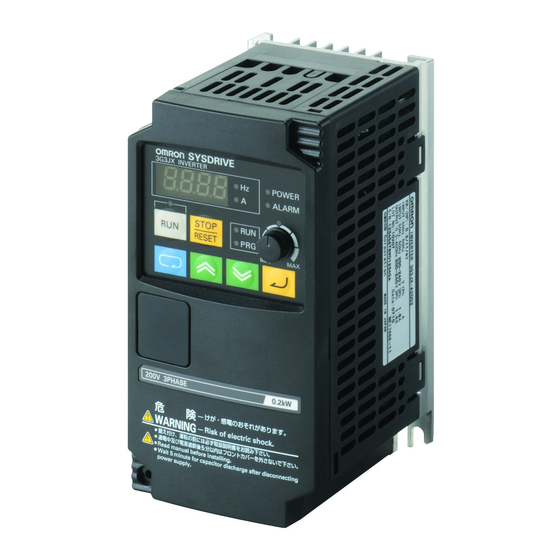
- Page 1 Cat. No. I558-E2-02-X Compact and complete Model: JX 200 V Class Three-Phase Input 0.2 to 7.5 kW 200 V Class Single-Phase Input 0.2 to 2.2 kW 400 V Class Three-Phase Input 0.4 to 7.5 kW USER’S MANUAL...
- Page 3 After reading this manual, keep it handy for future reference. This manual describes the specifications and functions of the product as well as the relations between them. You should assume that anything not described in this manual is not possible with the product.
- Page 4 PRODUCTS, WHETHER SUCH CLAIM IS BASED ON CONTRACT, WARRANTY, NEGLIGENCE, OR STRICT LIABILITY. In no event shall the responsibility of OMRON for any act exceed the individual price of the product on which liability is asserted. IN NO EVENT SHALL OMRON BE RESPONSIBLE FOR WARRANTY, REPAIR, OR OTHER CLAIMS...
-
Page 5: Application Considerations
The following are some examples of applications for which particular attention must be given. This is not intended to be an exhaustive list of all possible uses of the products, nor is it intended to imply that the uses listed may be suitable for the products: •... - Page 6 PERFORMANCE DATA Performance data given in this manual is provided as a guide for the user in determining suitability and does not constitute a warranty. It may represent the result of OMRON's test conditions, and the users must correlate it to actual application requirements.
-
Page 7: Safety Precautions
Wiring work must be carried out only by qualified personnel. Not doing so may result in a serious injury due to an electric shock. Be sure to ground the unit. Not doing so may result in a serious injury due to an electric shock or fire. - Page 8 Doing so might result in a small-scale fire, heat generation or damage to the unit. Install a stop motion device to ensure safety. Not doing so might result in a minor injury. (A holding brake is not a stop motion device designed to ensure safety.) Be sure to use a specified type of braking resistor/regenerative braking unit.
- Page 9 “Suitable for use on a circuit capable of delivering not more than 100k rms symmetrical amperes, 480V maximum when protected by Class CC, G, J or R fuses or circuit having an interrupting rating not less than 100,000 rms symmetrical amperes, 480 volts maximum”. For the 400V models “Install device in pollution degree 2 environment”.
- Page 10 •Locations subject to shock or vibration. Transporting, Installation, and Wiring •Do not drop or apply a strong impact on the product. Doing so may result in damaged parts or malfunction. •Do not hold by the front cover, but hold by the fins during transportation.
-
Page 11: Product Disposal
Precautions for Correct Use Installation •Mount the product vertically on a wall or on a DIN track (optional) with the product's longer sides upright. The material of the wall has to be nonflammable such as a metal plate. Main Circuit Power Supply •Confirm that the rated input voltage of the Inverter is the same as AC power supply voltage. - Page 12 Precautions for Correct Use Warning Labels Warning labels are located on the Inverter as shown in the following illustration. Be sure to follow the instructions. Warning Description...
- Page 13 Checking Before Unpacking Checking the Product On delivery, be sure to check that the delivered product is the Inverter JX model that you ordered. Should you find any problems with the product, immediately contact your nearest local sales representative or OMRON sales office.
-
Page 14: Revision History
Revision History Revision History A manual revision code appears as a suffix to the catalog number located at the lower left of the front and back covers. I558-E2-02 Cat. No. Revision code Revision code Revision date Changes and revision pages... -
Page 15: About This Manual
About This Manual About This Manual This User's Manual is compiled chapter by chapter for user's convenience as follows. Understanding the following configuration ensures more effective use of the product. Overview Chapter 1 Overview Describes features and names of parts. - Page 16 About This Manual...
-
Page 17: Table Of Contents
Chapter 2 Design Installation....................2-2 Wiring.......................2-7 Chapter 3 Operation Test Run Procedure.................3-3 Test Run Operation .................3-4 Part Names and Descriptions of the Digital Operator......3-8 Operation Procedure (Example: Factory Default)3-10 Parameter Transition ................3-16 Parameter List ..................3-17 Chapter 4 Functions Monitor Mode...................4-2 Function Mode ..................4-6... - Page 18 Contents Chapter 7 Specifications Standard Specification List..............7-2 Measurement Method of Output Voltage ..........7-6 Dimensional Drawing ................7-7 Options....................7-13 Appendix Appendix-1Parameter List ................. App-2 Appendix-2Product Life Curve ................App-18 Index...
-
Page 19: Functions
Chapter 1 Overview 1-1 Functions ............1-2 1-2 Appearance and Names of Parts ....1-4... - Page 20 JX-AB007 1.5 kW JX-AB015 2.2 kW JX-AB022 International Standards Models (EC Directives and UL/cUL Standards) The JX Inverter meets the EC Directives and UL/cUL standard requirements for worldwide use. Classification Applicable standard EMC Directive EN61800-3: 2004 EC Directives Low-voltage Directive...
-
Page 21: Installation
Moreover, the three-phase 200 V, three-phase 400 V, and single/three-phase 200 V common types are made to meet the power supply specifications for use outside Japan. PID Function The PID function is featured for the easier control of the fan and pump. It helps to control airflow and pressure. Emergency Shutoff Function Switching the dedicated switch (S8) changes from the multi-function input (input 3) to the emergency shutoff input. -
Page 22: Appearance And Names Of Parts
•The size of the fin varies with the motor capacity. •There are two sizes depending on the motor capacity, but the fundamental structure is the same. •Remove the front cover when connecting the power supply, the motor, and the control signal. - Page 23 S8: Emergency shutoff function selector (Default = OFF) (Caution) Do not switch the emergency shutoff function selector (S8) without reason as the allocation of the multi-function input terminals may change. For details, refer to "Emergency Shutoff Input Function" (page 4-46).
- Page 25 Chapter 2 Design 2-1 Installation ............2-2 2-2 Wiring ..............2-7...
-
Page 26: Wiring
Wiring work must be carried out only by qualified personnel. Not doing so may result in a serious injury due to an electric shock. Be sure to ground the unit. Not doing so may result in a serious injury due to an electric shock or fire. (200-V class: type-D grounding, 400-V class: type-C grounding) CAUTION Do not connect resistors to the terminals (PD+1, P/+, N/-) directly. - Page 27 2-1 Installation Transporting, Installation, and Wiring •Do not drop or apply strong impact on the product. Doing so may result in damaged parts or malfunction. •Do not hold by the front cover, but hold by the fins during transportation. •Do not connect an AC power supply voltage to the control input/output terminals. Doing so may result in damage to the product.
- Page 28 •Keep the Inverter away from heating elements (such as a braking resistor, DC reactor, etc.). If the Inverter is installed in a control panel, keep the ambient temperature within the range of the specifications, taking dimensions and ventilation into consideration.
- Page 29 2-1 Installation •To raise the carrier frequency, reduce the output current (or derate the rated current) as shown in the graph below. (1) Ambient temperature 40°C 0.2 to 2.2 · 5.5/7.5kW 200-V Class 0.4 to 2.2 · 5.5/7.5kW 400-V Class...
- Page 30 2-1 Installation •Before installing the Inverter, place a cover over all the ventilation openings to shield them from foreign objects. After completing the installation process, be sure to remove the covers from the Inverter before operation. Ventilation openings (Both sides and top)
- Page 31 Removing and Mounting the Front Cover Removing the Front Cover Loosen the mounting screw at the lower left of the front cover. Lift the bottom of the front cover to remove while holding the body. 1. Loosen the front cover mounting screw.
- Page 32 2-2 Wiring Mounting the Front Cover Hang the upper side of the front cover on the hooks, and push down both sides of the cover simultaneously until it clicks into place. 1. Hang the upper side on the hooks. (Two hooks)
- Page 33 Motor rotation speed *1.) Use terminals L1 and N for single phase model JX-AB *2.) If the main circuit is turned on at the same time as a RUN command is input, the motor begins to rotate at least 2.0 seconds later.
- Page 34 (Select an earth leakage breaker having a higher sensed leakage current and avoid unnecessary operation.) If the wiring between the Inverter and the motor is too long (longer than 10 m), the motors thermal relay may malfunction due to harmonics. Install an AC reactor on the Inverter output side, or use a current sensor instead of the motors thermal relay.
- Page 35 2-2 Wiring Note 2: Connect securely to the ground as specified (type-D grounding for 200-V class, and type-C grounding for 400-V class). Do not share the grounding electrode with other strong electrical devices. Example of incorrect grounding Example of correct grounding...
- Page 36 Ground connection is not required. Connect to the ground terminal of the Inverter. Note 4: Keep the wiring away from the power cable of the main circuit and from the wiring on the relay control circuit. (More than 10 cm apart)
- Page 37 Selecting the Sequence Input Method (Sink/Source Logic) Logic Selection Method for the Multi-function Input Terminals When the internal power supply is used, you can switch the logic by rearranging the short-circuit bar on the control circuit terminal block. The default setting is sink logic.
- Page 38 •To connect seven wires or more to the control circuit terminal block, use a shield line of 0.5 mm or less. •Strip the signal line by 5 to 6 mm, and connect the exposed wire. (In the case of stranded wires, make sure that the wires are not unraveled.) •Make sure that the maximum outside diameter of the signal cable is 2.0 mm or less (except for the alarm signal...
- Page 39 2-2 Wiring Choose the sensitivity current of the earth leakage breaker (ELB), depending on the total distance (L) between the Inverter and the power supply, and the Inverter and the motor. For models with build-in filter a time delay ELB could be necessary in some cases.
- Page 40 PD/+1 and P/+ when a DC Ground terminal electric shock and reduce noise.) reactor is not connected. For JX-AB 's terminal symbols, R/L1 corresponds to L1, S/L2 to L2, and T/L3 to N/L3. Connect a single-phase 200-V AC input to terminals L1 and N. 2-16...
- Page 41 •The Inverter's output uses high-speed switching, and so generates high-frequency current leakage. (Generally, if the power cable is 1 m, the leakage current is approx. 100 mA per Inverter, and approx. 5 mA is added per additional meter of the power cable.) •At the power supply input part, install a special-purpose ground fault interrupter for Inverters that...
- Page 42 Installing a Magnetic Contactor (MC) •If the power supply of the main circuit is shut off due to sequencing, a magnetic contactor (MC) can be used. (When forcibly stopping the load with an MC on the primary side of the main circuit, however, the regenerative braking does not work and the load coasts to a stop (free run).)
- Page 43 This is extremely hazardous. Be careful not to short-circuit the output wires. Do Not Use a Phase Advance Capacitor or Noise Filter •Doing so may result in damage to the Inverter or cause the parts to burn. Never connect a phase advance capacitor or LC/RC noise filter to the output circuit.
- Page 44 Cable Length Between Inverter and Motor Use a cable of 50 m or less between the Inverter and the motor. If the cable length is increased, the stray capacitance between the Inverter outputs and the ground is increased proportionally. An increase in stray capacitance causes high-frequency leakage current to increase, affecting the current detector in the Inverter's output unit and peripheral devices.
- Page 45 P1. 50 mA max. speed ⎯ Output signal common Contact ratings 250 V AC 2.0 A (resistance load) 100 V AC min. Relay output 0.2 A (inductive load) 10 mA signal Under normal operation : AL2-AL0 Closed 30 V DC 3.0 A (resistance load) 5 V DC...
- Page 46 *1. Simultaneous input of current and voltage is not possible. Do not connect the signal lines simultaneously. *2. By factory default, multi-function output 11 is set to NO contact. To switch to NC contact, change the C031 setting. *3. Do not input negative voltage. Doing so may result in damage to the inverter...
- Page 47 5 V DC 100 mA AL1 AL2 AL0 Inside the Inverter (Factory default) By factory default, the relay output (AL2, AL1) contact selection (C036) is set at NC contact between AL2-AL0, and NO contact between AL1-AL0. Mode Selector RS-485 Communication/Operator Selector (S7) Select the mode according to the option connected to the communications connector.
-
Page 48: Important Notes
EC directive conforming products. This in turn does not allow us to confirm the condition and the conformity in which our products are used. Therefore, we appreciate confirmation of the final EMC conformity for the whole machine or equipment on your own. - Page 49 Y-capacitors may effect on the Earth Leakage Breaker (ELB) at input side. Please refer to the following table to help selecting ELB. Note that the values are nominal ones only flow via the capacitor. Leakage current from the motor cable and motor should also be considered when selecting the ELB.
- Page 50 (one crosses over the other), the interference is smallest if they intersect at an angle of 90°. Cables susceptible to interference should therefore only intersect motor cables, intermediate circuit cables, or the wiring of a rheostat at right angles and never be laid parallel to them over longer distances.
- Page 51 Chapter 3 Operation 3-1 Test Run Procedure ......... 3-3 3-2 Test Run Operation.......... 3-4 3-3 Part Names and Descriptions of the Digital Operator ............3-8 3-4 Operation Procedure (Example: Factory Default) ................3-10 3-5 Parameter Transition ........3-16 3-6 Parameter List ..........3-17...
-
Page 52: Safety Information
Do not remove the front cover during the power supply and 5 minutes after the power shutoff. Doing so may result in a serious injury due to an electric shock. Do not operate the Digital Operator or switches with wet hands. Doing so may result in a serious injury due to an electric shock. -
Page 53: Test Run Procedure
Data display : Displays the set value in d001. •If an error occurs, the error code is displayed on the data display. In this case, refer to "Chapter 5 Maintenance Operations" and make the necessary changes to remedy. Parameter Initialization Initialize the parameters. -
Page 54: Test Run Operation
•Make sure that the motor output terminals (U/T1, V/T2, and W/T3) are connected to the motor correctly. •Make sure that the control circuit terminals and the control device are wired correctly and that all control terminals are turned off. •Set the motor to no-load status (i.e., not connected to the mechanical system). - Page 55 •To initialize the parameters, set parameter b084 to "02". Key sequence Display example Description Power On Press the Mode key once, and then press the Decrement key three times to b--- display "b---". Press the Mode key. b001 "b001" is displayed.
- Page 56 Press the Mode key. "H003" is displayed. 0.20 Press the Mode key. The set value in "H003" is displayed. 0.40 Use the Increment or Decrement key to set the rated motor capacity. 0.40 Press the Enter key. The set value is entered. h003 (In approx.
- Page 57 •Start the no-load motor (i.e., not connected to the mechanical system) using the Digital Operator. * Before operating the Digital Operator, check that the FREQ adjuster is set to "MIN." * Make sure that the LED indicator above the FREQ adjuster and the RUN command LED indicator are lit.
-
Page 58: Part Names And Descriptions Of The Digital Operator
RUN (during RUN) LED Lit when the Inverter is running. indicator Lit when the set value of each function is indicated on the data display. PROGRAM LED indicator Blinks during warning (when the set value is incorrect). Displays relevant data, such as frequency reference, output current, and set... -
Page 59: Monitor Mode
(To change the set value, be sure to press the Enter key.) Enter key Do not press the Enter key if you don’t want to store any changes, for example, if you have changed the data inadvertently. Changes the mode. - Page 60 Displaying the Monitor Mode, Basic Function Mode, and Extended Function Mode Power On 1. The data of the set monitor is displayed. (Default is "0.0") Press 2. The code of the monitor mode is displayed (as "d001"). •Press the Mode key once to return from the code...
- Page 61 3-4 Operation Procedure (Example: Factory Default) 3. The code of the basic function mode is displayed (as "F001"). f001 Press Press (4 times) (4 times) 4. The extended function mode is displayed (as "A---"). •Extended function mode Displays in order of A ⇔ b ⇔ C ⇔ H.
- Page 62 •Switch the method of the RUN command. (Digital Operator → Control terminal block) •To switch the method of the RUN command from the Digital Operator (factory default) to the control terminal block, you need to change the frequency reference selection (A001) from the Digital Operator (02) to the terminal (01).
-
Page 63: Function Mode
•You can enter codes for the monitor mode, basic function mode, and extended function mode directly, as well as through the scrolling method. •Below is an example where code d001 of the monitor mode is changed to extended function A029. 1. Display the code of the monitor mode (as "d001"). - Page 64 ("A" is entered.) 3. Change the 3rd digit of the function code. •"0" of the 3rd digit blinks. •Press the Enter key to fix "0" of the 3rd digit as a001 you need not change it. •Press the Mode key to start "A" blinking again.
- Page 65 •If you enter a parameter number that is not included in the parameter list, the display returns to the parameter previously displayed. •Press the Enter key to shift the digit to the right, and the Mode key to shift to the left. 3-15...
- Page 66 , etc.) * To display a specific monitor when the power is turned on, press the Enter key with that monitor displayed. If a parameter for an extended function code is stored after pressing the Enter key, however, that code (A---, b---, C---, d---, or H---) appears at the next power-on.
-
Page 67: Parameter List
Error code (condition of occurrence) → Output frequency [Hz] → Output current [A] → 001C to ⎯ ⎯ d082 Fault monitor 2 Internal DC voltage [V] → RUN time [h] → 0025 ON time [h] 0026 to d083 Fault monitor 3 002F ⎯... - Page 68 1000. to 3000. Operator rotation direction 00: Forward ⎯ F004 1018 selection 01: Reverse * 2nd control is displayed when SET(08) is allocated to one of the digital inputs. Extended function mode Change Modbus Parameter Monitor or data range Default Function name...
- Page 69 (Digital Operator) setting (Hex) Multi-step speed A020 0.0/Starting frequency to Max. frequency 1029 4-12 reference 0 *2nd multi-step A220 0.0/Starting frequency to 2nd max. frequency 150F 4-12 speed reference 0 Multi-step speed A021 102B reference 1 Multi-step speed A022 102D...
- Page 70 0.0/Frequency lower limit to Max. frequency 105A 4-20 *2nd frequency upper A261 0.0/Frequency lower limit to 2nd Max. frequency 1517 limit A062 Frequency lower limit 0.0/Starting frequency to Frequency upper limit 105B 4-20 *2nd frequency lower 0.0/Starting frequency to 2nd frequency upper A262 1518 limit...
- Page 71 Default Function name during Unit Address Page (Digital Operator) setting (Hex) 00: OFF (Deviation = Target value - Feedback value) ⎯ A077 Reverse PID function 106E 4-22 01: ON (Deviation = Feedback value - Target value) PID output limit A078 0.0 to 100.0...
- Page 72 ⎯ b011 Active Frequency 01: Max. frequency 1170 4-30 Matching restart 02: Set frequency Electronic thermal Rated b012 10AD level current 0.2 × Rated current to 1.0 × Rated current 4-32 *2nd electronic Rated b212 1527 thermal level current 3-22...
- Page 73 1529 02: Enabled in constant speed operation selection 1.5 × b022 Overload limit level Rated 10B6 current 0..1 × Rated current to 1.5 × Rated current 4-33 1.5 × *2nd overload limit b222 Rated 152A level current Overload limit...
- Page 74 2.0 to 12.0 10D2 4-63 00: Clears the trip monitor ⎯ b084 Initialization selection 01: Initializes data 10D3 4-41 02: Clears the trip monitor and initializes data Initialization ⎯ b085 10D4 4-41 parameter selection * Do not change. Frequency ⎯...
- Page 75 52: RDY (ready function) 53: SP-SET (special 2nd function) Multi-function input 5 C005 1107 64: EMR (emergency shutoff selection 255: No function *1. The EMR is set forcibly with switch S8, not *2nd multi-function with parameters. C205 1536 input 5 selection 3-25...
- Page 76 111B 4-62 01: Output current Multi-function output C031 terminal 11 contact 111D selection 00: NO contact at AL2; NC contact at AL1 ⎯ 4-61 01: NC contact at AL2; NO contact at AL1 Relay output (AL2, C036 AL1) contact 1122...
- Page 77 00: Do not store the frequency data ⎯ C101 UP/DWN selection 1149 4-53 01: Store the frequency data 00: Trip reset at rising edge of RS input 01: Trip reset at falling edge of RS input ⎯ C102 Reset selection 114A 4-51...
- Page 78 3-6 Parameter List Change Modbus Parameter Monitor or data range Default Function name during Unit Address Page (Digital Operator) setting (Hex) Output terminal 11 C145 0.0 to 100.0 1154 4-60 OFF delay Relay output ON C148 0.0 to 100.0 1157...
- Page 79 Chapter 4 Functions 4-1 Monitor Mode............ 4-2 4-2 Function Mode..........4-6...
-
Page 80: Monitor Mode
F: Forward o: Stop r: Reverse PID Feedback Value Monitor [d004] Displays a feedback value converted by [A075] (PID scale) when the PID selection is enabled ([A071] = 01). "Monitor display" = "PID feedback value (%)" × "PID scale" [A075]... - Page 81 Displays the output status of the multi-function output terminals and relay output terminals. C031 and C036 (contact selection) are excluded so this monitor indicates the signal status of the functions (C021 and C026) allocated to each multi-function output terminal disregarding the normal- ly open or close selection.
- Page 82 Displays the Inverter RUN time. (Display) 0. to 9999. : Displays in increments of 1 hour. 1000 to 9999 : Displays in increments of 10 hours. ⎡100 to ⎡999 : Displays in increments of 1000 hours. Power ON Time Monitor [d017] Displays the total power supply time of the Inverter.
- Page 83 (Display) 0.0 to 999.9 : Displays in increments of 0.1 V. Electronic Thermal Monitor [d104] Displays the count integration value of the electronic thermal. An overload trip occurs if it reaches 100% (E05). (Display) 0.0 to 100.0 : Displays in increments of 0.1%.
- Page 84 Related parameters A001, A201, C001 to C005 * To switch to the 2nd multi-step speed, allocate 08 (SET) to the multi-function input terminal and then turn it on. Acceleration/Deceleration Time Set an acceleration/deceleration time for the motor. For a slow transition, set a large value, and for a fast transition, set a small one.
- Page 85 F003/F203 F002/F202 Even if a short acceleration/deceleration time is set, the actual time cannot be shorter than the minimum acceleration/deceleration time that is determined by the mechanical inertia moment and the motor torque. If you set a time shorter than the minimum time, an overcurrent/overvoltage trip may occur.
- Page 86 Related parameters F004, A005, C001 to C005 * To switch to the 2nd RUN command, allocate 08 (SET) to the multi-function input terminal and then turn it on. Data RUN command source Turn ON/OFF by FW and RV allocated to the terminal.
- Page 87 Maximum Frequency Set the maximum value of the output frequency. •The value set here will be the maximum value (e.g.,10 V in the range from 0 to 10 V) of the external analog input (frequency reference). •The maximum Inverter output voltage from base to maximum frequencies is the voltage set at AVR voltage selection A082.
- Page 88 Related parameters A003, A203, A081, A082 * To switch to the 2nd max. frequency, allocate 08 (SET) to the multi-function input terminal and then turn it on. Analog Input (O, OI, VR) Two types of external analog inputs are available for frequency reference plus the built-in VR For voltage input, you can set a frequency from 0 to maximum by applying a voltage from 0 to 10 V between inputs O and L.
- Page 89 01: 0 Hz A155 Related parameters A005, A016, AT input •To input voltage ranging from 0 to 5 V on the O-L terminal, set A014 to 50%. (Example 1) A015/A105 = 00 (Example 2) A015/A105 = 01 Max. frequency Max. frequency...
- Page 90 Related parameters F001, C001 to C005, CF1 to CF4 inputs Required settings F001, A001 = 02 * To switch to the 2nd multi-step speed reference 0, allocate 08 (SET) to the multi-function input terminal and then turn it on. 4-12...
- Page 91 Multi-step speed setting binary 4 Binary operation 4: OFF •By allocating 02 to 05 (CF1 to CF4) to any of the multi-function inputs, you can select the multi- step speed from 0 to 15. Note that multi-step speed terminals not allocated to any multi-function input are regarded as "OFF".
- Page 92 Jogging operation Stop Related parameters C001 to C005 •If the frequency is set to a higher value, the jogging operation may easily lead to a trip. Adjust A038 so that the Inverter does not trip. (When A039 = 01) Output frequency A038 •...
- Page 93 2nd output voltage gain Related parameters A082, H003/H203, H004/H204 * To switch to the 2nd control, allocate 08 (SET) to the multi-function input terminal and then turn it on. Control Method (V/f Characteristics) Constant Torque Characteristics (VC) •Ouput voltage is proportional to output frequency.
- Page 94 4-2 Function Mode Special Reduced Torque Characteristics (Special VP) •Suitable for a fan or pump that requires torque in a low speed range using VC characteristics at this area.. Output voltage (100%) (1.7th power) Output frequency (Hz) 10% of base Base frequency Max.
- Page 95 Frequency control mode: DB operates when the frequency reaches the specified level during operation. •If DC injection braking operates at a high motor speed, an overcurrent trip (E01 to E04) or overload trip (E05) may occur. For internal DC injection braking, the following adjustment may help you avoid such a situation: Lower the DC injection braking frequency (A052).
- Page 96 •Set the DC injection braking power in A054. •If the DC injection braking delay time (A053) is set, the Inverter output will be shut off during the specified time period and the motor goes into free-run status. After the set time elapses, DC injection braking starts.
- Page 97 •Set the frequency for starting DC injection braking in A052. •If the DC injection braking delay time (A053) is set, the output is shut off when the frequency reaches the level set in A052 during deceleration, and free-run status arises for the specified period.
- Page 98 [A061] 2nd frequency lower 0.0/Starting frequency to Frequency A262 limit upper limit [A261] Related parameters C001 to C005 * To switch to the 2nd control, allocate 08 (SET) to the multi-function input terminal and then turn it on. 4-20...
- Page 99 A062 Frequency reference 20mA If the lower limit is set, the set value is prioritized even if 0 V (4 mA) is input for frequency reference. Frequency Jump Function This function helps avoid resonant points of loaded machines. Parameter No.
- Page 100 4-2 Function Mode PID Function This function enables process control of such elements as flow rate, air volume, and pressure. Parameter No. Function name Data Default setting Unit 00: Disabled ⎯ A071 PID selection 01: Enabled ⎯ A072 PID P gain 0.2 to 5.0...
- Page 101 Available output terminals 11-CM2, AL2-AL0 (or AL1-AL0) Required settings C021, C026, C044 •C044 can be set from 0 to 100. Setting corresponds to the range of 0 to the maximum target value. Feedback value C044 Target value C044 •...
- Page 102 •Operation where the control volume is proportional to the variation ratio of the target value Target value Large Large A074 A074 Small Control volume Small •PI operation is the combination of the above P and I operations; PD is P and D operations; PID is P, I and D operations. 4-24...
- Page 103 AL1 (C026). •Set the upper limit in C052, and the lower limit in C053. When the PID feedback value falls below the lower limit, the terminal is turned on. The ON state will remain until the value exceeds the upper limit.
- Page 104 4-2 Function Mode AVR Function •This function outputs voltage to the motor correctly even if the incoming voltage to the Inverter fluctuates. With this function, output voltage to the motor is based on that set in the AVR voltage selection. Parameter No.
- Page 105 Related parameters F002, F003, F202, F203, C001 to C005 * To switch to the 2nd control, allocate 08 (SET) to the multi-function input terminal and then turn it on. •The acceleration/deceleration time can be switched via the multi-function input terminal or automatically with an arbitrary frequency.
- Page 106 0. to 100. 100. 00: External start selection ⎯ A105 OI start selection 01: 0 Hz Related parameters A005, A011 to A015, A016, A151 to A155, AT input For each item, refer to "External Frequency (Voltage/Current) Adjustment" (page 4-11). 4-28...
- Page 107 Operator selection 01: Subtraction (A - B) 02: Multiplication (A × B) Related parameters A001 = 10 •Inputs O and OI cannot be set simultaneously. Do not connect the signal lines for inputs O and OI simultaneously. A141 Digital Operator A143...
- Page 108 <Group B: Detailed Function Parameter> Momentary Power Interruption/Trip Retry (Restart) This function allows you to determine the operation performed when a trip occurs due to momentary power interruption, undervoltage, overcurrent, or overvoltage. Set the retry condition according to your system.
- Page 109 Alarm Alarm [t0: Duration of momentary power interruption / t1: Allowable duration of momentary power interruption (b002) / t2: Retry wait time (b003)] Alarm Selection for Momentary Power Interruption/Undervoltage During Stop •Use b004 to select whether to enable an alarm output in case of momentary power interruption or undervoltage.
- Page 110 •Provides the most appropriate protection characteristics, taking into account the decline of a standard motor cooling capability at a low speed. •To set a value over the rated current of the motor, be careful of any temperature rise of the motor. Parameter No.
- Page 111 (Outputs OL signal when the C241 2nd overload warning level Rated current overload warning level is reached.) Related parameters C021, C026 * To switch to the 2nd control, allocate 08 (SET) to the multi-function input terminal and then turn it on. 4-33...
- Page 112 With 01 selected, the analog voltage input between O and L is enabled, and 10 V here corresponds to 150% of the rated current. Note that 01 can be set only if PID is disabled and the AT terminal is not set.
- Page 113 Use this function to prohibit writing of each parameter. This helps prevent data rewrite due to erroneous operation. For the soft lock selection through the signal input from the terminal (b031 = 00 or 01), refer to the Soft Lock Function of the Multi-function Input section in "Reset" (page 4-50).
-
Page 114: Operation Description
4-2 Function Mode Momentary Power Interruption Non-stop Function This function decelerates the Inverter by a controlled stop to avoid a trip or free running in case of power supply disconnection or momentary power interruption during operation. Parameter No. Function name... - Page 115 •Though quicker response is expected with a larger proportional gain, control tends to be divergent and may easily lead to a trip. • Response also becomes quicker with a shorter integral time, but if too short, it may lead to a trip as well.
- Page 116 Note that the actual deceleration time may be longer than the set value. If DC voltage exceeds the set level, the Inverter stops deceleration. The aim of this function is the same as the overvoltage control function during deceleration, described in b055 and b056. However, these functions have different deceleration characteristics and you can select either function according to your system.
- Page 117 Starting frequency 0.5 to 9.9 •Use mainly to adjust the starting torque. •With the starting frequency set high, the starting current increases. Therefore, the current may exceed the overload limit and cause an overcurrent trip Output frequency b082 Output voltage...
- Page 118 Inverter. •Carrier frequency adjustment also helps avoid mechanical or motor resonance. •To raise the carrier frequency, reduce the output current (or derate the rated current) as shown in the graph below.
- Page 119 Displayed value [d007] = "Output frequency [d001]" x "Frequency conversion coefficient [b086]" Refer to page for more details STOP Key Selection You can select whether to enable the STOP key on the Digital Operator, even if the RUN command is set to the control terminal block (terminal). Parameter No. Function name...
- Page 120 With RUN command selection A002 set to 01 (control terminal), the motor restarts only if the FW terminal is turned on, even in free running. •You can select the Inverter output mode for restart at free-run stop selection b088 (0 Hz start or Active Frequency Matching restart). (Examples 1, 2) •The setting of this function is also applied to stop selection b091.
- Page 121 4-2 Function Mode Cooling Fan Control •Used to operate the built-in cooling fan of the Inverter all the time, only while the Inverter is in operation or when Fin temperature is to high. This function applies to the Inverter models with a built-in cooling fan.
- Page 122 <Group C: Multi-function Terminal Function> The JX has five input terminals [1], [2], [3], [4] and [5]; one open collector output terminal [11]; two relay output terminals [AL2] and [AL1] (SPDT contact); and one analog output terminal [AM].
- Page 123 C015 operation selection * To switch to the 2nd control, allocate 08 (SET) to the multi-function input terminal and then turn it on. Note 1: The terminal with "18" (RS) allocated will automatically have an NO contact specifications. Note 2: "19" (PTC) can only be allocated to multi-function input 5 (C005).
- Page 124 4-2 Function Mode Emergency Shutoff Input Function Emergency Shutoff Mode Selection To select Emergency Shutoff mode in the JX, turn on switch S8 on the right side behind the front cover. Switch S8 (right side) [Notes] Use caution when turning on/off the DIP switch S8 on the control PCB. That will change the function allocation on the control terminal block automatically.
- Page 125 The STOP/RESET button on the Digital Operator cannot be used for resetting Emergency Shutoff status. * When DIP switch S8 is ON, the EMR function is forcibly set to NC contact, and the RS function to NO contact.(Parameters C013 and C014 are ignored)
- Page 126 •By allocating 08 (SET) or 53 (SP-SET) to the desired multi-function input and then turning on/off the SET or SP-SET terminal, you can switch and control two different motors. •Switch to the 2nd control function at the SET terminal after turning off the RUN command and the Inverter output.
- Page 127 H006/H206 Stabilization parameter •There's no indication of 2nd control functions on the display. You'll see which one is enabled by checking whether the terminal is turned on/off. •Switching the 2nd control using SET during operation does not work until the Inverter stops.
- Page 128 The Inverter starts running immediately after a trip reset if the RUN command is still turned on. (Example 2) •To return from a USP trip to normal operation, shut off the power, turn off the RUN command, turn on the power again, and then turn on the RUN command. (Example 3) •Allocate 13 (USP) to the desired multi-function input.
- Page 129 (Example 1) (Example 2) Alarm Alarm Thermistor Trip Function This function protects the motor by tripping with the built-in thermistor detecting a temperature rise. Data Symbol Function name Status Description When the thermistor is connected between terminals 5...
- Page 130 4-2 Function Mode 3-wire Input Function This function is effective in using auto recovery contacts such as a press button switch for operation and stop. Data Symbol Function name Status Description Starts with auto recovery contacts. 3-wire start Irrelevant to the motor operation.
- Page 131 •You can store a frequency set value after UP/DWN adjustment. Choose whether to store the value with C101. Also, you can clear the stored frequency set value by allocating 29 (UDC) to the desired multi- function input and turning on/off the UDC terminal.
- Page 132 Required settings A001, A002 •When the input of this signal is reset, A001 and A002 return to the command status prior to the input. •If you switch on/off this function during operation, the RUN command is reset to stop the Inverter.
- Page 133 10: ODc (Do not use.) 43: LOC (light load detection signal) •You can allocate the following functions to multi-function output terminal 11 and the relay output terminals. •While the multi-function output terminal 11 selection is for open collector output (allocated in C021), the relay output (AL2, AL1) function selection is for SPDT-contact relay output (allocated in C026).
- Page 134 4-2 Function Mode •Also outputs a signal during DC injection braking. Below is the time chart. Output frequency RUN output Frequency Arrival Signal This function outputs a signal when the output frequency has reached the set value. Data Symbol Function name Status...
-
Page 135: Alarm Output
Output frequency Alarm Output This is output when the Inverter trips. If you use the relay for alarm outputs, set and check operation,, as the SPDT contact is used for the terminals. For details, refer to the description of the relay output, "Multi-function Output Terminal ON Delay/OFF Delay"... -
Page 136: Network Error
500 ms Network Error This function detects and outputs a network error during RS485 ModBus communication. •The error is output during RS485 ModBus communication if the next signal does not come even after the specified time period in C077. Data... - Page 137 4-2 Function Mode Logic Operation Result Output This function outputs a logic operation result of combination of two functions. Data Symbol Function name Status Description Logic operation output See the figure below. Available output terminals 11-CM2, AL2-AL0 (or AL1-AL0) Required settings...
- Page 138 4-2 Function Mode Light Load Detection Signal This function outputs a signal when the Inverter output current has fallen below the C039 set value. Data Symbol Function name Status Description Output current is lower than the C039 set value. Light load detection signal Output current is higher than the C039 set value.
- Page 139 (without delay) ON delay only OFF delay only ON and OFF delays Multi-function Output Terminal Contact Selection This function allows you to set either contact for the two multi-function output terminals respectively. Parameter No. Function name Data Default setting Unit...
- Page 140 The output method is the same as the output frequency. Monitor accuracy is ±10% at the halfway point of base frequency. AM Adjustment •You can adjust the calibration of the analog voltage (0 to 10 V DC) from the AM terminal on the control terminal block by using the Inverter setting. Parameter No.
- Page 141 2nd motor pole number selection Related parameters A041 to A045, A241 to A244 * To switch to the 2nd control, allocate 08 (SET) to the multi-function input terminal and then turn it on. Stabilization Parameter This function helps to reduce motor hunting.
- Page 142 4-2 Function Mode Communication Function •Communication with external network control devices can be carried out from the communication connector of the JX, through the RS-485 complying ModBus-RTU protocol. Communication Specifications Item Description Note Transfer speed 4800/9600/19200 bps Select using the Digital Operator.
- Page 143 2. Set parameter C070 to "02" (OPE) using the Digital Operator and save it. 3. Shut off the power. 4. Set the 485/OPE selector S7 to "OPE" and connect the external OPE to the RJ45 connector. 5. Turn on the power and start external OPE communications.
- Page 144 ModBus communication requires the following settings. Be sure to set the parameters shown below. In case the parameter settings are changed, ModBus communication will not start until the Inverter is turned ON again, even if "485" is selected with the 485/OPE selector.
- Page 145 (1): Frame to be sent from the external controller to the Inverter (Query) (2): Frame to be returned from the Inverter to the external controller (Response) The Inverter returns a response (Frame (2)) only after receiving a query (Frame (1)) and does not output a response positively.
- Page 146 <Error Check> •CRC (Cyclic Redundancy Check) is used for the ModBus-RTU error check. •The CRC code is 16-bit data generated for the block of random length data in the 8-bit unit. •To generate the CRC code, the generation polynomial CRC-16 (X +1) is used.
- Page 147 •If the query is the loopback function code (08h), the Inverter sends back a response of the same content as the query. •If the query contains a function code of writing into the holding register or coil (05h, 06h, 0Fh, 10h), the Inverter sends back the query as it is in response.
- Page 148 CRC-16 (LSB) *1. Broadcasting cannot be performed. *2. When specifying the value for 0 or over 31 of the reading coils, the error code "03h" is sent. *3. Data is transferred by the number of data bytes. The data received as the response shows the statuses of coils 7 to 14. The data received here, "05h = 00000101b", should be read with setting coil 7 as LSB as follows:...
- Page 149 CRC-16 (LSB) *1.Broadcasting cannot be performed. *2.Data is transferred by the number of data bytes. In this example, 12 ("0Ch") bytes are used since 6 pieces of holding register data are returned. *3.Note that the holding register start address is "0011h", which is smaller by 1 than the register number "0012h".
- Page 150 *1. There is no response for broadcasting. *2. Note that the coil start address is "0", which is smaller by 1 than the coil number "1". The coil addresses for coil numbers from "1 to 31" are "0 to 30".
- Page 151 CRC-16 (LSB) *1. There is no response for broadcasting. *2. Note that the holding register start address is "1028h", which is smaller by 1 than the register number "1029h". Refer to "<Exception Response>" (4-75) if writing into the holding register cannot be performed nor- mally.
- Page 152 *1.There is no response for broadcasting. *2.Since the change data comprises both MSB and LSB as a set, make the byte to be an even num- ber by adding 1, even if the byte which actually needs to be changed is an odd number.
- Page 153 CRC-16 The detailed field configuration is shown on the next page. The function code of the exception re- sponse is the value of the query function code with 80h added. The exception code shows the cause of exception response. 4-75...
- Page 154 To Save the Change to the Holding Register (enter command) Even if using the command to write into the holding register (06h) or into the consecutive holding registers (10h), no change can be saved in the EEPROM memory element of the Inverter. If the Inverter power shuts off without saving any changes, the holding register returns to the status before the changes were made.
- Page 155 If the master cannot reset the coil ON status due to communication disconnection, turn the control circuit terminal block from ON to OFF in order to turn OFF the coil *2. The content of a communications error is retained until a fault reset is input. (Available to reset during operation)
- Page 156 If the master cannot reset the coil ON status due to communication disconnection, turn the control circuit terminal block from ON to OFF in order to turn OFF the coil *2. The content of a communications error is retained until a fault reset is input. (Available to reset during operation)
- Page 157 0.1 [V] 116Dh Electronic thermal monitor d104 0 to 1000 0.1 [%] F002 1 to 300000 1014h (MSB) The second decimal place is ignored Acceleration time 1 0.01 [s] when the value is over 10000 (100.0 F002 1015h seconds). (LSB) 4-79...
- Page 158 Resolution Function F202 1 to 300000 1501h (MSB) The second decimal place is ignored 2nd acceleration time 1 0.01 [s] when the value is over 10000 (100.0 F202 1502h seconds). (LSB) F003 1 to 300000 1016h (MSB) The second decimal place is ignored Deceleration time 1 0.01 [s]...
- Page 159 Frequency lower limit A062 : b082 × 10 to Frequency upper limit 0.1 [Hz] : A061 × 10 0.0/Starting frequency 1518h 2nd frequency lower limit A262 : b082 x 10 to 2nd frequency upper limit 0.1 [Hz] : A261x10 4-81...
- Page 160 0.1 [%] accuracy adjustment A092 1 to 300000 1074h (MSB) The second decimal place is ignored Acceleration time 2 0.01 [s] when the value is over 10000 (100.0 A092 1075h seconds). (LSB) A292 1 to 300000 1519h (MSB) The second decimal place is ignored 2nd acceleration time 2 0.01 [s]...
- Page 161 Operator selection A143 02: Multiplication (A × B) 1091h Frequency addition amount A145 0 to 4000 0.1 [Hz] 00: Adds the A145 value to the output frequency ⎯ 1093h Frequency addition direction A146 01: Subtract A145 value from output frequency...
- Page 162 1172h b030 200 to 20000 0.01 [%] restart level 00: Data other than b031 cannot be changed when terminal SFT is ON. 01: Data other than b031 and the specified frequency parameter cannot be changed when terminal SFT is ON.
- Page 163 20 to 120 0.1 [kHz] 00: Clears the trip monitor 01: Initializes data ⎯ 10D3h Initialization selection b084 02: Clears the trip monitor and initializes data Initialization parameter 00: Fixed ⎯ 10D4h b085 selection *Do not change. Frequency conversion...
- Page 164 2nd multi-function input 2 CF3/05: CF4/06: JG/07: DB/08: SET/09: 1533h C202 selection 2CH/11: FRS/12: EXT/13: USP/15: SFT/ Multi-function input 3 16: AT/18: RS/19: PTC terminal 5 only/ 1105h C003 selection 20: STA/21: STP/22: F/R/23: PID/24: ⎯ PIDC/27: UP/28: DWN/29: UDC/31:...
- Page 165 Do not change. ⎯ 1149h UP/DWN selection C101 00: OFF/01: ON 00: Trip reset at power-on 01: Trip reset when the power is OFF ⎯ 114Ah Reset selection C102 02: Enabled only during trip (Reset when the power is ON.)
- Page 166 4-2 Function Mode Register Parameter Function name Monitor or data range Resolution Function 00: 0.2/02: 0.4/04: 0.75/ ⎯ 1165h Motor capacity selection H003 06: 1.5/07: 2.2/09: 3.7/ 11: 5.5/12: 7.5 00: 0.2/02: 0.4/04: 0.75/ ⎯ 1541h 2nd motor capacity selection H203 06: 1.5/07: 2.2/09: 3.7/...
-
Page 167: Special Display List (Error Codes)
Chapter 5 Maintenance Operations 5-1 Special Display List (Error Codes) ....5-2 5-2 Troubleshooting..........5-6... - Page 168 07 voltage on the converter exceeds the specified level. Shuts off the output if an error occurs in the EEPROM built into the Inverter due to external noise and abnormal temperature rise. •Check the set data again if the error occurs.
- Page 169 Appears if the incoming voltage has remained high for 100 seconds e 15 trip while the Inverter output is stopped. Shuts off the output if the temperature has risen in the main circuit due Temperature error e 21 to malfunction of the cooling fan or other reasons.
- Page 170 Description Operator Reset Appears with the [RS] terminal turned ON or during initialization. Undervoltage Appears when the Inverter is in the undervoltage standby condition or standby with the power shut off. Restart during momentary power The restart function is in operation.
- Page 171 (2) Output frequency (Hz) when the trip occurred (3) Output current (A) when the trip occurred 398. (4) DC voltage (V) between P and N when the trip occurred (5) Total time of operation before the trip (6) Total time of power distribution before the trip...
- Page 172 • Is the RUN key (RUN command) C001 to C005 turned on? • Turn on the RUN key (RUN • Are FW (or RV) input and terminal L or command). PCS connected? • Connect FW (or RV) input to terminal L or PCS.
- Page 173 Notes on Data Setting: Wait 6 seconds or more after changing data and pressing the Enter key to store it. The data may not be set correctly if you operate any key, perform the reset, or disconnect the power supply within 6 seconds.
- Page 174 5-2 Troubleshooting...
-
Page 175: Inspection And Maintenance
Chapter 6 Inspection and Maintenance 6-1 Inspection and Maintenance ......6-2 6-2 Storage.............. 6-8... -
Page 176: Inspection And Maintenance
Precautions for Use Operation Stop Command •Provide a separate emergency stop switch because the STOP key on the Digital Operator is valid only when function settings are performed. •When checking a signal during the power supply and the voltage is erroneously applied to the control input terminals, the motor may start abruptly. -
Page 177: General Precautions
* For JX-AB@@@'s terminal symbols, R/L1 corresponds to L1, S/L2 to L2, and T/L3 to N/L3. • Make sure that the resistance between the main circuit terminal and ground is 5 MΩ or more at 500 V DC megger. •Do not conduct a withstand voltage test on any part of the Inverter. - Page 178 *1. The life of the capacitor depends on ambient temperatures. Refer to the product life curve in Appendix-2. When the capacitor stops operating at the end of the product's life, the Inverter must be replaced. *2. Clean the Inverter periodically. Accumulated dust in or on the cooling fan or heat sink can cause the Inverter to overheat.
- Page 179 *1. The life of the capacitor depends on ambient temperatures. Refer to the product life curve in Appendix-2. When the capacitor stops operating at the end of the product's life, the Inverter must be replaced. *2. Clean the Inverter periodically. Accumulated dust in or on the cooling fan or heat sink can cause the Inverter to overheat.
- Page 180 *1. The life of the capacitor depends on ambient temperatures. Refer to the product life curve in Appendix-2. When the capacitor stops operating at the end of the product's life, the Inverter must be replaced. *2. Clean the Inverter periodically. Accumulated dust in or on the cooling fan or heat sink can cause the Inverter to overheat.
- Page 181 Note 1: For voltage, use a measurement device that displays effective values of fundamental wave. For current and electric power, use a measurement device that displays all effective values. Note 2: The Inverter output waveform, under PWM control, may have a margin of error, especially at a low frequency.
- Page 182 (Without condensation or freezing due to rapid temperature change) •Do not store this unit in a place with dust, direct sunshine, corrosive gas, or combustible gas. •The Inverter's smoothing capacitor characteristics will deteriorate if left unused for a long time,...
- Page 183 Chapter 7 Specifications 7-1 Standard Specification List ......7-2 7-2 Measurement Method of Output Voltage ..7-6 7-3 Dimensional Drawing........7-7 7-4 Options.............. 7-13...
-
Page 184: Standard Specification List
200V 11.0 Rated output capacity (kVA) 240 V 13.3 Rated input voltage 3-phase (3-wire) 200 V -15% to 240 V +10%, 50/60 Hz ±5% Built-in filter Rated input current (A) 13.0 20.0 30.0 40.0 Rated output voltage 3-phase: 200 to 240 V (Proportional to input voltage) Rated output current (A) 10.0... - Page 185 DC injection braking frequency control available *1. The applicable motor is a 3-phase standard motor. For using any other type, be sure that the rated current does not exceed that of the Inverter. *2. Output voltage decreases according to the level of the power supply voltage.
-
Page 186: Standard Specification List
Setting with the FREQ adjuster and the Increment/Decrement keys on the Digital Operator, variable resistance from 1 to 2 kΩ (2 W), 0 to 10 V DC (input impedance 10 kΩ), 4 to 20 mA (input impedance 250 Ω), communication through an RS-485... - Page 187 Options Noise filter, AC/DC reactors, regenerative braking unit and resistor, etc. *1. To operate the motor at over 50/60 Hz, contact the motor manufacturer to find out the maximum allowable number of revolutions. *2. For the stable control of the motor, the output frequency may exceed the maximum frequency set in A004...
-
Page 188: Measurement Method Of Output Voltage
Motor T/L3 W/T3 Diode 600 V 0.01 A min. (200-V class) 1000 V 0.1 A min. (400-V class) 220 kΩ Effective value of fundamental wave: VAC = 1.1 × VDC * For JX-AB 's terminal symbols, use L1 and N. -
Page 189: Dimensional Drawing
7-3 Dimensional Drawing 7-3 Dimensional Drawing JX -A2002 AB002... - Page 190 7-3 Dimensional Drawing JX -A2004 AB004...
- Page 191 7-3 Dimensional Drawing JX -A2007...
- Page 192 7-3 Dimensional Drawing JX -A4004 -AB007 7-10...
- Page 193 7-3 Dimensional Drawing JX -A2015/A2022/A2037 -A4007/A4015/A4022/A4040 -AB015/AB022 7-11...
- Page 194 7-3 Dimensional Drawing JX -A2055/A2075 -A4055/A4075 7-12...
-
Page 195: Options
Leakage Power Applied Filter Rated dimensions dimensions Rated current Fixing supply inverter reference current L x W x H X x Y (Kg) Volt Nom/Max (mm) (mm) JX-A2002 193 x 81 x JX-A2004 AX-FIJ2006-RE 250V 183 x 57 JX-A2007 JX-A2015... -
Page 196: Specifications
7-4 Options Input AC Reactor (AX-RAI Dimensional Drawing Specifications Applicable Dimensions Weight Characteristics Inverter JX- Reference Inductance Current value (mH) A2002 to A2015 AX-RAI02800080-DE 120 1.78 A2022 to A2037 AX-RAI00880175-DE 120 2.35 0.88 17.5 A2055 to A2075 AX-RAI00350335-DE 180 0.35 33.5... - Page 197 (mH) 0.2 - 0.7 AX-RC 1.5 - 2.2 AX-RC 200V AX-RC 5.5 - 7.5 AX-RC Under development (Contact with your Omron representative) 0.4 - 0.7 AX-RC 1.5 - 2.2 AX-RC 400V AX-RC 5.5 - 7.5 AX-RC Output AC Reactor (AX-RAO...
-
Page 198: Dimensional Drawing
< 2.2 AX-FEM2515-RE < 15 Digital Operator (3G3AX-OP01) Data display RUN command LED indicator Operation keys FREQ adjuster 2-M3 Depth 5 20.5 2-φ4 Panel cutout dimension External dimensions Height (55 mm) × Width (70 mm) × Depth (10 mm) 7-16... - Page 199 Appendix Appendix-1Parameter ListApp-2 Appendix-2Product Life CurveApp-18...
- Page 200 Fault frequency ⎯ ⎯ ⎯ d080 0. to 9999. monitor Fault monitor 1 (Latest) Error code (condition of occurrence) → d081 Output frequency [Hz] → Output current [A] ⎯ ⎯ d082 Fault monitor 2 → Internal DC voltage [V] → RUN time [h] →...
- Page 201 30. to Max. frequency [A004] *2nd base A203 30. to Max. frequency [A204] frequency Maximum A004 frequency 30. to 400. *2nd maximum A204 frequency * 2nd control is displayed when SET (08) is allocated to one of from C001 to C005. App-3...
- Page 202 Multi-step speed A020 0.0/Starting frequency to Max. frequency reference 0 *2nd multi-step A220 0.0/Starting frequency to 2nd max. frequency speed reference 0 * 2nd control is displayed when SET (08) is allocated to one of from C001 to C005. App-4...
- Page 203 Jogging frequency 0.00/Starting frequency to 9.99 6.00 00: Free-run stop Jogging stop ⎯ A039 01: Deceleration stop selection 02: DC injection braking stop * 2nd control is displayed when SET (08) is allocated to one of from C001 to C005. App-5...
- Page 204 DC injection A055 0.0 to 60.0 braking time DC injection 00: Edge operation ⎯ A056 braking method 01: Level operation selection * 2nd control is displayed when SET (08) is allocated to one of from C001 to C005. App-6...
- Page 205 ⎯ A081 AVR selection 01: Always OFF 02: OFF during deceleration AVR voltage 200-V class: 200/215/220/230/240 200/ A082 selection 400-V class: 380/400/415/440/460/480 * 2nd control is displayed when SET (08) is allocated to one of from C001 to C005. App-7...
- Page 206 Acceleration 00: Line ⎯ A097 pattern selection 01: S-shape curve Deceleration 00: Line ⎯ A098 pattern selection 01: S-shape curve * 2nd control is displayed when SET (08) is allocated to one of from C001 to C005. App-8...
- Page 207 VR end ratio 0. to 100. 100. 00: Use VR start frequency [A151] ⎯ A155 VR start selection 01: 0 Hz start * 2nd control is displayed when SET (08) is allocated to one of from C001 to C005. App-9...
- Page 208 00: Reduced torque characteristics 1 ⎯ 01: Constant torque characteristics *2nd electronic 02: Reduced torque characteristics 2 thermal b213 characteristics selection * 2nd control is displayed when SET (08) is allocated to one of from C001 to C005. App-10...
- Page 209 03: Data other than b031 and the specified frequency parameter cannot be changed. 10: Data other than parameters changeable during operation cannot be changed. * 2nd control is displayed when SET (08) is allocated to one of from C001 to C005. App-11...
- Page 210 01: Initializes data selection 02: Clears the trip monitor and initializes data Initialization ⎯ b085 parameter * Do not change. selection * 2nd control is displayed when SET (08) is allocated to one of from C001 to C005. App-12...
- Page 211 01: Enabled function Automatic carrier 00: Disabled ⎯ b150 reduction 01: Enabled Ready function 00: Disabled ⎯ b151 selection 01: Enabled * 2nd control is displayed when SET (08) is allocated to one of from C001 to C005. App-13...
- Page 212 00: NO ⎯ C013 input 3 operation 01: NC selection Multi-function C014 input 4 operation selection Multi-function C015 input 5 operation selection * 2nd control is displayed when SET (08) is allocated to one of from C001 to C005. App-14...
- Page 213 PID deviation C044 0.0 to 100.0 excessive level C052 PID FB upper limit 0.0 to 100.0 C053 PID FB lower limit * 2nd control is displayed when SET (08) is allocated to one of from C001 to C005. App-15...
- Page 214 Communication C078 0. to 1000. wait time C081 O adjustment 0.0 to 200.0 100.0 C082 OI adjustment 0.0 to 200.0 100.0 * 2nd control is displayed when SET (08) is allocated to one of from C001 to C005. App-16...
- Page 215 Motor pole number H004 selection Pole *2nd motor pole H204 number selection Stabilization H006 parameter 0. to 255. *2nd stabilization H206 parameter * 2nd control is displayed when SET (08) is allocated to one of from C001 to C005. App-17...
- Page 216 The smoothing capacitor, which will deteriate due to the chemical reaction caused by parts temper- atures, should normally be replaced once every 5 years. However, if the ambient temperature is high, or the Inverter is used with a current exceeding the rated current, for example, under overload conditions, its life will be significantly shortened.
- Page 217 INDEX...
- Page 218 AM ........4-62...
- Page 219 OD ........4-23...
Need help?
Do you have a question about the JX and is the answer not in the manual?
Questions and answers