Omron RX Series User Manual
Inverter lcd digital operator
Hide thumbs
Also See for RX Series:
- User manual (688 pages) ,
- System configuration manual (19 pages) ,
- User manual (414 pages)

Subscribe to Our Youtube Channel
Related Manuals for Omron RX Series


Summary of Contents for Omron RX Series
- Page 1 Inverter RX Series LX Series MX2 Series LCD Digital Operator User’s Manual 3G3AX-OP05 I579-E2-01...
- Page 2 No patent liability is assumed with respect to the use of the information contained herein. Moreover, because OMRON is constantly striving to improve its high-quality products, the information contained in this manual is subject to change without notice. Every precaution has been taken in the preparation of this manual. Nevertheless, OMRON assumes no responsibility for errors or omissions.
-
Page 3: Introduction
Introduction Introduction Thank you for purchasing the LCD Digital Operator (Model: 3G3AX-OP05). This manual explains how to set parameters required to use the LCD Digital Operator (Model: 3G3AX-OP05), operation procedures and the remedies needed if problems occur. For the use of the LCD Digital Operator 3G3AX-OP05, please refer also to RX (I560-E2), LX (I120E-EN) or MX2 (I570-E2) User’s Manuals. -
Page 4: Manual Configuration
Manual Configuration Manual Configuration This manual is compiled section by section for user’s convenience as follows. Overview Section 1 Overview This section provides features and specifications of the LCD Digital Operator. Section 2 Part Names and Functions This section describes the part names and functions of the LCD Digital Operator. -
Page 5: Manual Structure
Manual Structure Manual Structure Page Structure and Symbol Icons The following page structure and symbol icons are used in this manual. Level 1 heading 4 Operation Procedures Level 2 heading Overview of Display Modes Level 3 heading 4-1-1 Transition of Screens The LCD Digital Operator basically displays its screens in four modes as shown below. -
Page 6: Special Information
Manual Structure Special Information Special information in this manual is classified as follows: Precautions for Safe Use Precautions on what to do and what not to do to ensure safe usage of the product. Precautions for Correct Use Precautions for Correct Use Precautions on what to do and what not to do to ensure proper operation and performance. -
Page 7: Sections In This Manual
Sections in this Manual Sections in this Manual Overview Part Names and Functions Installation and Wiring Operation Procedures LCD Digital Operator Related Parameters Read/Write Functions Error Messages and Troubleshooting Maintenance Index LCD Digital Operator User’s Manual (I579) -
Page 8: Table Of Contents
CONTENTS CONTENTS Introduction ....................... 1 Manual Configuration ....................2 Manual Structure ....................... 3 Sections in this Manual .................... 5 CONTENTS......................... 6 Read and Understand this Manual ................8 Safety Precautions ....................11 Precautions for Safe Use..................13 Precautions for Correct Use................... 15 Regulations and Standards .................. -
Page 9: Contents
CONTENTS Section 4 Operation Procedures Overview of Display Modes ....................4-2 4-1-1 Transition of Screens ........................4-2 4-1-2 Overview of Each Mode......................4-3 4-1-3 Changing the Display in Each Mode................... 4-5 Operation in the Monitor Mode A................... 4-6 Operation in the Monitor Mode B................... 4-7 Operation in the Function Mode .................... -
Page 10: Read And Understand This Manual
OF PROFITS OR COMMERCIAL LOSS IN ANY WAY CONNECTED WITH THE PRODUCTS, WHETHER SUCH CLAIM IS BASED ON CONTRACT, WARRANTY, NEGLIGENCE, OR STRICT LIABILITY. In no event shall the responsibility of OMRON for any act exceed the individual price of the product on which liability is asserted. - Page 11 Application Considerations SUITABILITY FOR USE OMRON shall not be responsible for conformity with any standards, codes, or regulations that apply to the combination of products in the customer’s application or use of the products. At the customer’s request, OMRON will provide applicable third party certification documents identifying ratings and limitations of use that apply to the products.
-
Page 12: Dimensions And Weights
Performance data given in this manual is provided as a guide for the user in determining suitability and does not constitute a warranty. It may represent the result of OMRON’s test conditions, and the users must correlate it to actual application requirements. Actual performance is subject to the OMRON Warranty and Limitations of Liability. -
Page 13: Safety Precautions
Safety Precautions Safety Precautions Indications and Meanings of Safety Information This manual uses the following precautionary symbols and signal words to ensure the safe use of the LCD Digital Operator. The precautions explained in this section describe important information regarding safety and must be followed without fail. The precautionary symbols and signal words used in this manual and their meanings are explained below. - Page 14 Safety Precautions WARNING Turn off the power supply and implement wiring correctly. Not doing so may result in a serious injury due to an electric shock. Wiring work must be carried out only by qualified personnel. Not doing so may result in a serious injury due to an electric shock. Do not change wiring and slide switches (SW1), put on or take off Operator and optional devices, replace cooling fans while the input power is being supplied.
-
Page 15: Precautions For Safe Use
Precautions for Safe Use Precautions for Safe Use Installation and Storage Do not store or use the product in the following places. • Locations subject to direct sunlight. • Locations subject to ambient temperature exceeding the specifications. • Locations subject to relative humidity exceeding the specifications. •... -
Page 16: Maintenance And Inspection
Precautions for Safe Use Maintenance and Inspection • When disposing of LCD digital operators and wasted batteries, follow the applicable ordinances of your local government. When disposing of the battery, insulate it using tape. The following display must be indicated when products using lithium primary batteries (with more than 6 ppb of perchlorate) are transport to or through the State of California, USA. -
Page 17: Precautions For Correct Use
Precautions for Correct Use Precautions for Correct Use Retry Selection Function • Be sure to confirm the RUN signal is turned off before resetting the alarm because the machine may abruptly start. Operation Stop Command • Provide a separate emergency stop switch because the STOP Key on the Operator is valid only when function settings are performed. -
Page 18: Regulations And Standards
Regulations and Standards Regulations and Standards Overseas Use To export (or provide to nonresident aliens) any part of this product that falls under the category of goods (or technologies) for which an export certificate or license is mandatory according to the Foreign Exchange and Foreign Trade Control Law of Japan, an export certificate or license (or service transaction approval) according to this law is required. -
Page 19: Items To Check After Unpacking
Items to Check after Unpacking Items to Check after Unpacking After unpacking the product, check the following items: • Is this the model you ordered? • Was there any damage sustained during shipment? Checking the Nameplate the following nameplate labels on its rear face The product has Checking the Model 3 G 3 A X - O P 0 5... -
Page 20: Related Manuals
Related Manuals Related Manuals To operate this product, you must be familiar with the equipment connected to it. Please refer to the following manual for information on the related product. Name Catalog No. RX User’s Manual I560-E2 LX User’s Manual I120E-EN MX2 User’s Manual I570-E2... -
Page 21: Revision History
Revision History Revision History The manual revision code is a number appended to the end of the catalog number found in the bottom right-hand corner of the front and back covers. Example I579-E2-01 Cat. No. Revision code Revision Revision Date Revised Content Code January 2013... - Page 22 Revision History LCD Digital Operator User’s Manual (I579)
-
Page 23: Overview
Overview This section provides features and specifications of the LCD Digital Operator. 1-1 Features ........... . . 1-2 1-2 Supported Models . -
Page 24: Features
1 Overview Features This LCD Digital Operator is intended for use with the RX, LX or MX2 inverter series. It can be connected with the RX and LX inverters directly or with the RX, LX and MX2 inverters via cable (optional). The LCD Digital Operator provides the following features: 5-Line English LCD A large 5-line LCD displays the name and setting range of parameters as well as the parameter... - Page 25 1 Overview Precautions for Safe Use • If the clock command is used in Drive Programming, an unexpected operation may occur due to weak battery. Take measures such as detecting a weak battery by a check that the clock data returns to the initial setting and stopping the Inverter or programs. When the LCD Digital Operator is removed or disconnected, Drive Programming is in a waiting status by the clock command.
-
Page 26: Supported Models
1 Overview Supported Models RX series inverter (Model: 3G3RX-). LX series inverter (Model: 3G3LX-). MX2 series inverter (Model: 3G3MX2-). 1 - 4 LCD Digital Operator User’s Manual (I579) -
Page 27: Specifications
1 Overview Specifications Item Specification Electrical Input power supply 4.9 to 5.2 VDC specifications voltage Transmission method RS-422 (R45) Transmission rate 19.2 Kbps/4,800 bps (switching) Environment Ambient operating –10 to 50°C temperature Ambient operating 20% to 90% (with no condensation) humidity Ambient storage –20 to 65°C... -
Page 28: External Dimensions
1 Overview External Dimensions The following figures show the dimensions of LCD Digital Operator and panel cut dimensions to install. When installing the LCD Digital Operator to the control panel, secure it from the back side using M3 screws (5 mm). The recommended torque is 0.9 to 1.0 N·m. -
Page 29: Recommended Cables
1 Overview Recommended Cables Use any of the following cables when installing the LCD Digital Operator separately from the RX, LX or MX2 inverter series. Digital Operator cables • 3G3AX-CAJOP300-EE (Cable length: 3 m) LCD Digital Operator User’s Manual (I579) 1 - 7... - Page 30 1 Overview 1 - 8 LCD Digital Operator User’s Manual (I579)
-
Page 31: Part Names And Functions
Part Names and Functions This section describes the part names and functions of the LCD Digital Operator. 2-1 Part Names ........... 2-2 2-2 Operation Keys . -
Page 32: Part Names
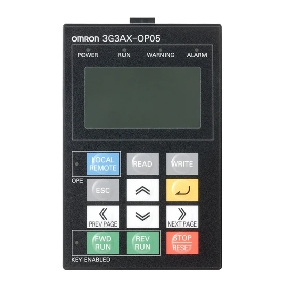
2 Part Names and Functions Part Names 3. WARNING LED 2. RUN (Operation) LED 4. ALARM LED 1. POWER LED 7. LCD display 5. Remote LED 8. Operation keys 6. RUN command LED indicator 9. RJ45 connector 10. Mounting holes (M3: 2 positions) 2 - 2 LCD Digital Operator User’s Manual (I579) -
Page 33: Operation Keys
2 Part Names and Functions Name Color Description POWER LED Green Lights when power is supplied to the LCD Digital Operator. RUN (Operation) Green Lights during Inverter operation. WARNING LED Lights when the Inverter parameter settings are incorrect. ALARM LED Lights when the Inverter trips. -
Page 34: Operation Keys
2 Part Names and Functions Operation Keys Operation keys Key image Name Function Switches between the Local and Remote modes. If the key is pressed for 2 seconds or more, the mode is switched; from Local to Remote or from Remote to Local. When the LCD LOCAL REMOTE Digital Operator is in the Local mode, the Remote (OPE) LED is lit. - Page 35 2 Part Names and Functions Key image Name Function Moves the cursor down. It is also used to decrease the parameter number or parameter Decrement key value. Moves the cursor to the left. In Navigation level display mode, moves to the previous mode. PREV PAGE key Moves the cursor to the right.
-
Page 36: Lcd Display
2 Part Names and Functions LCD Display Backlight The LCD display has two backlight colors; white and orange. The color of the backlight indicates the state of the Inverter, as shown in the following table. Backlight color State White Normal (No relation to the RUN/Stop state of the Inverter) Orange Warning (Parameter mismatch) White/Orange... - Page 37 2 Part Names and Functions Item Display item Description STOP Stop Inverter RUN status Forward Reverse Complete display Individual display of functions Setting in b037 User setting display (Display Selection) Data comparison display Basic display LCD Digital Operator User’s Manual (I579) 2 - 7...
- Page 38 2 Part Names and Functions 2 - 8 LCD Digital Operator User’s Manual (I579)
-
Page 39: Installation And Wiring
Installation and Wiring This section provides information on the installation and wiring of the LCD Digital Operator. 3-1 Installation on the Inverter ........3-2 3-1-1 Direct Installation on the Inverter (RX, LX models) . -
Page 40: Installation On The Inverter
3 Installation and Wiring Installation on the Inverter This section shows how to install the LCD Digital Operator on the RX, LX and MX2 inverter series. The installation procedure differs with installation methods. This section describes the following 2 methods. •... -
Page 41: Direct Installation On The Inverter
3 Installation and Wiring 3-1-1 Direct Installation on the Inverter (RX, LX models) This section describes the procedure for installing the LCD Digital Operator directly on the Inverter. Precautions for Correct Use Precautions for Correct Use The LCD Digital Operator cannot be installed directly on an Inverter that is already mounted with a Communications Unit. -
Page 42: Installation On The Inverter Via Cable
3 Installation and Wiring 3-1-2 Installation on the Inverter via Cable (RX, LX, MX2 models) If necessary, mount theLCD Digital Operator to the panel. Cut out the panel according to the panel cutout diagram and, using M3 screws, secure the LCD Digital Operator to the panel from the back side. -
Page 43: Checking The Operation After Installation
3 Installation and Wiring 3-1-3 Checking the Operation After Installation After checking that the system and surrounding areas are safe, turn ON the power supply to the Inverter. Check the LCD Digital Operator display. The installation is completed successfully if the following Monitor screen is displayed. However, when the power is supplied to the LCD Digital Operator for the first time after purchase, when the built-in battery is consumed, or when the power supply is turned on for the first time after battery replacement, the following screen appears, which prompts you to set the clock. -
Page 44: Date And Time Setting
3 Installation and Wiring 3-1-4 Date and Time Setting If the screen, which prompts you to set the clock, appears as shown below, press the ESC key to return to the normal screen and simultaneously press the , and keys to enter the Option Mode. Select Date and Time by pressing the key to set the current date and time. - Page 45 Operation Procedures This section provides an overview of the display modes supported by LCD Digital Operator and how to operate the LCD Digital Operator in each display mode. For the Option Mode, refer to Section 5 LCD Digital Operator Related Parameters. For the Read/Write Mode, refer to Section 6 Read/Write Functions.
-
Page 46: Operation Procedures
4 Operation Procedures Overview of Display Modes 4-1-1 Transition of Screens The basic display screens of LCD Digital Operator are displayed in four modes as shown below. Each mode has two levels: the higher Navigation level and the lower Edit level. The user can move between each mode in the Navigation level only. -
Page 47: Overview Of Each Mode
4 Operation Procedures These modes can be called at any level and in any operating state. Press the ESC key to restore the operating state before the call. Read Write Option Press three keys simultaneously. Mode Mode Mode Option Select the setting item. Mode Option Change the set values of... -
Page 48: Function Mode
4 Operation Procedures Function Mode In this mode, “F to U” group Inverter parameters can be displayed and set. The screen shows the parameter number, function name, parameter data and setting range of the parameter. Precautions for Correct Use Precautions for Correct Use In the Function Mode, “d”... -
Page 49: Changing The Display In Each Mode
4 Operation Procedures Write Mode In this mode, the Inverter parameter settings and Case: 5. R/W Storage Mode = “01 :Single” Drive Programming program data stored in the LCD Digital Operator can be all written to the Inverter. Change the number of storage data by selecting 5. R/W Storage Mode in the OPTION MODE menu. -
Page 50: Operation In The Monitor Mode A
4 Operation Procedures Operation in the Monitor Mode A At the Navigation level, press the key to select the Monitor Mode A (MONITOR-A) screen. Press the key to show the cursor on the “d” group monitor function. Press the key to select the monitor function to display on the MONITOR-A screen. -
Page 51: Operation In The Monitor Mode B
4 Operation Procedures Operation in the Monitor Mode B At the Navigation level, press the key to select the Monitor Mode B (MONITOR-B) screen. Press the key to show the cursor in the first parameter line of the “d” group monitor function. Press the key to move between the four inverter parameters. -
Page 52: Operation In The Function Mode
4 Operation Procedures Operation in the Function Mode At the Navigation level, press the key to select the Function Mode screen. Press the key. The cursor moves to the parameter number. Then, press the , or key to select the parameter No. to change. -
Page 53: Operation In The Trip Mode
4 Operation Procedures Operation in the Trip Mode At the Navigation level, press the key to select the Trip Mode screen. Press the key to show the information on the past trips (six trip errors) recorded in the Inverter and the information on the warning (one warning). The information on one trip error comprises two pages. - Page 54 4 Operation Procedures 4 - 10 LCD Digital Operator User’s Manual (I579)
-
Page 55: Parameter Setting
LCD Digital Operator Related Parameters This section describes the Inverter parameters related to the LCD Digital Operator. 5-1 Parameter Setting ..........5-2 5-1-1 Operation in the Option Mode . -
Page 56: Parameter Setting
5 LCD Digital Operator Related Parameters Parameter Setting The LCD Digital Operator parameters can be set and changed in the Option Mode. The Option Mode provides the following nine settings: 1. Language 2. Date and Time 3. Read Lock 4. INV Type Select 5. - Page 57 5 LCD Digital Operator Related Parameters Press the to move the cursor over 2. Date and Time in the second line. In 2. Date and Time, press the key. The cursor moves over the date and time data. Press the key to move among the day, month, year, and time data.
-
Page 58: Details Of Each Option Mode Parameter
5 LCD Digital Operator Related Parameters 5-1-2 Details of Each Option Mode Parameter The table below shows the setting of each Option Mode item. Item Description Setting range Default 1. Language Select the display language. 01: English 2. Date and Set the date and time for the LCD Digital Format 1: (YYYY/MM/DD) 2009/01/01... - Page 59 5 LCD Digital Operator Related Parameters Item Description Setting range Default 7. Backlight Set this to enable or disable the orange 01: Enable Flicker backlight illumination. 02: Disable 8. Operator Use this function to reset the LCD Digital 01: YES Reset Operator to its default settings.
-
Page 60: Related Inverter Parameters
5 LCD Digital Operator Related Parameters Related Inverter Parameters The table below shows the RX and MX2 Inverter parameters related to the LCD Digital Operator. For details, please refer to RX (I560-E2) or MX2 (I570-E2) User’s Manuals. Default Parameter No. Function name Data Unit... - Page 61 5 LCD Digital Operator Related Parameters The table below shows the LX Inverter parameters related to the LCD Digital Operator. For details, please refer to LX (I120E-EN) User’s Manual. Default Parameter No. Function name Data Unit value F010 STOP Key Enable 00: Enable –...
- Page 62 5 LCD Digital Operator Related Parameters 5 - 8 LCD Digital Operator User’s Manual (I579)
-
Page 63: Read/Write Functions
Read/Write Functions This section describes how to read and write Inverter parameter settings using the LCD Digital Operator. 6-1 Single READ Function ......... . 6-2 6-2 Single WRITE Function . -
Page 64: Single Read Function
6 Read/Write Functions Single READ Function The Single READ function is enabled when 5. R/W Storage Mode in the OPTION MODE menu is set to “01: Single”. The Single Read function is executed immediately just by pressing the key. The Single READ function reads a single set of Inverter parameter setting data and a Drive Programming program and stores them to the LCD Digital Operator. -
Page 65: Single Write Function
6 Read/Write Functions Single WRITE Function The Single WRITE function is enabled when 5. R/W Storage Mode in the OPTION MODE menu is set to “01: Single”. The Single WRITE function is executed immediately just by pressing the key. The Single WRITE function writes a single set of Inverter parameter setting data and a Drive Programming program stored in the LCD Digital Operator to the connected Inverter. -
Page 66: Quad Read Function
6 Read/Write Functions Quad READ Function The Quad READ function is enabled when 5. R/W Storage Mode in the OPTION MODE menu is set to “02: Quad”. The Quad READ function provides the following two operations. • Reads a single set of all Inverter parameter setting data and stores up to four sets in the specified memory number 1 to 4. - Page 67 6 Read/Write Functions After pressing the key, an overwriting confirmation message appears on the screen. To proceed, press the key. To cancel, press the key. Completed Completed After 2 seconds Precautions for Correct Use Precautions for Correct Use • The Quad READ function cannot be executed by pressing the key in the Write Mode or Option Mode.
-
Page 68: Quad Verify Function
6 Read/Write Functions Quad VERIFY Function The Quad VERIFY function is enabled when 5. R/W Storage Mode in the OPTION MODE menu is set to “02: Quad”. The Quad VERIFY function provides the following operations. • Verifies the read data of a single set of Inverter parameter setting data and the parameter data stored in a specified memory number. - Page 69 6 Read/Write Functions Automatic Automatic transition transition When the verification of the parameter setting data or Drive Programming program is completed, the result appears. • Match: matched • Unmatch: unmatched Precautions for Correct Use Precautions for Correct Use • The Quad VERIFY function cannot be executed by pressing the key in the Write Mode or Option Mode.
-
Page 70: Quad Write Function
6 Read/Write Functions Quad WRITE Function The Quad WRITE function is enabled when 5. R/W Storage Mode in the OPTION MODE menu is set to “02: Quad”. The Quad WRITE function provides the following two operations. • Writes a single set of all Inverter parameter setting data, which is stored in a specified memory number 1 to 4, to the connected Inverter. - Page 71 6 Read/Write Functions After pressing the key, you can select one of the following operations under Select data. 01: Write data (writes parameter setting data) 02: Write data+EzSQ (writes parameter setting data and a Drive Programming program) 03: Cancel (cancels the operation) Note When the memory number 2, 3, or 4 is selected, the above selecion numbers (01 and 03)
-
Page 72: Conditions For The Read/Write Operations
6 Read/Write Functions Conditions for the Read/Write Operations The read/write operations may not be executed depending on the state and setting of the Inverter. The operation conditions are shown below. Conditions for Read/Verify Operations (from Inverter to LCD Digital Operator) Parameter setting data and Inverter state and setting Parameter settings only... -
Page 73: Error Messages And Troubleshooting
Error Messages and Troubleshooting This section describes the error messages and troubleshooting of the LCD Digital Operator. 7-1 Error Messages and Remedies ........7-2 7-1-1 Inverter Error Messages . -
Page 74: Error Messages And Remedies
7 Error Messages and Troubleshooting Error Messages and Remedies The error messages that appear on the LCD Digital Operator screen are categorized into the following three: Inverter Trip Inverter Warning LCD Digital Operator Error * Screen flashes alternately in white * Screen is illuminated in orange * Screen remains in white and orange... - Page 75 7 Error Messages and Troubleshooting Message Cause Check items Remedies Reset method INV in RUN • An attempt was • The WRITE key was • Press the WRITE Press the mode made to write pressed during key when the STOP/RESET parameter data Inverter operation.
-
Page 76: Troubleshooting
7 Error Messages and Troubleshooting Message Cause Check items Remedies Reset method Read & Copy • Writing to the • In the Option Mode, • Stop the Inverter Press the only Inverter is disabled. set the INV Type and Drive STOP/RESET Select to "01: Type Programming if they... -
Page 77: Troubleshooting
7 Error Messages and Troubleshooting Troubleshooting This section describes the troubleshooting of LCD Digital Operator problems. For the troubleshooting of Inverter problems, please refer to RX (I560-E2), LX (I120E-EN) or MX2 (I570-E2) User’s Manuals. No Data is Displayed on the Screen The inverter power supply is ON. - Page 78 7 Error Messages and Troubleshooting Key Operations are Ignored The Inverter operation is normal. Reset the Inverter. The cable is connected properly Turn OFF the Inverter power supply, between the Inverter and the LCD connect the cable properly, and then Digital Operator.
- Page 79 7 Error Messages and Troubleshooting LCD Digital Operator has a Dark Screen or Displays Unreadable Characters The cable is connected properly The LCD Digital Operator is between the Inverter and the LCD defective. Replace the LCD Digital Digital Operator. Operator. The recommended cable is used.
- Page 80 7 Error Messages and Troubleshooting 7 - 8 LCD Digital Operator User’s Manual (I579)
-
Page 81: Maintenance
Maintenance This section provides information on the maintenance of the LCD Digital Operator. 8-1 Battery Replacement ......... . . 8-2 LCD Digital Operator User’s Manual (I579) 8 - 1... -
Page 82: Battery Replacement
8 Maintenance Battery Replacement The LCD Digital Operator contains a battery, which is a service part. This built-in battery is used as a backup for the clock function of the LCD Digital Operator. Below is the procedure for replacing this part. Purpose of the Built-in Battery This LCD Digital Operator has a built-in real time clock IC for the date and time information. - Page 83 8 Maintenance Remove the four screws located on the rear face of the LCD Digital Operator to disassemble the chassis. Remove the old battery using a thin slotted screwdriver. Be careful not to damage the PCB and its parts. When disposing of the old battery, insulate it using such as tape according to the specified method to prevent short-circuit.
- Page 84 8 Maintenance Precautions for Safe Use • When disposing of LCD digital operators and wasted batteries, follow the applicable ordinances of your local government. When disposing of the battery, insulate it using tape. The following display must be indicated when products using lithium primary batteries (with more than 6 ppb of perchlorate) are transport to or through the State of California, USA.
-
Page 85: Index
Index LCD Digital Operator User’s Manual (I579) Index-1... - Page 86 Index Index Backlight ................ 2-6 Function Mode ............4-4, 4-8 Monitor Mode A ............4-3, 4-6 Monitor Mode B ............4-3, 4-7 Option Mode ............4-5, 5-2 Purpose of the Built-in Battery ........8-2 Read Mode ..............4-4 Trip Mode ...............4-4, 4-9 wasted batteries ............8-4 Write Mode ..............
- Page 88 The Netherlands IL 60173-5302 U.S.A. Tel: (31)2356-81-300/Fax: (31)2356-81-388 Tel: (1) 847-843-7900/Fax: (1) 847-843-7787 © OMRON Corporation 2013 All Rights Reserved. OMRON (CHINA) CO., LTD. OMRON ASIA PACIFIC PTE. LTD. In the interest of product improvement, Room 2211, Bank of China Tower, No.
Need help?
Do you have a question about the RX Series and is the answer not in the manual?
Questions and answers