Table of Contents
Advertisement
Quick Links
Advertisement
Table of Contents

Related Manuals for Teledyne BENTHOS UDB-9000


Summary of Contents for Teledyne BENTHOS UDB-9000
- Page 1 UDB-9000 Universal Deck Box UDB-9000-M (Portable) UDB-9000-MR (Rack Mount) Configurations User’s Manual P/N M-270-10, Rev. B Teledyne Benthos, Inc. 49 Edgerton Drive North Falmouth, MA 02556 U.S.A. Tel: (508) 563-1000 Fax: (508) 563-6444 www.benthos.com...
-
Page 2: Notices
(1) year from date of shipment from Teledyne Benthos, Inc. Purchaser's receipt of any product delivered hereunder shall be an... - Page 3 INC., ITS AGENTS OR EMPLOYEES SHALL CREATE A WARRANTY OR IN ANY WAY INCREASE THE SCOPE OF THIS LIMITED WARRANTY. ANY AND ALL LIABILITY OF TELEDYNE BENTHOS, INC. IS EXPRESSLY LIMITED TO THE PRICE PURCHASER HAS PAID FOR THE PRODUCT.
-
Page 4: Liability
Title shall pass to the Buyer on delivery to the carrier at North Falmouth, Massachusetts, U.S.A. Risk of damage or loss following such delivery shall be the Buyer's, and Teledyne Benthos shall in no way be responsible for safe arrival of the shipment. Title shall so pass to the Buyer regardless of any provision for payment of freight or insurance by Teledyne Benthos, and regardless of the form of the shipping documents. -
Page 5: Preface
Benthos DS-8750, DS-8000 and DS-7000 Acoustic Deck Sets and the ATM-891 Acoustic Telemetry Modem Deck Box into one unit. This capability enables the UDB-9000 to operate with all of the Teledyne Benthos acoustic releases, transponders and pop-up buoys, and to operate with the Teledyne Benthos acoustic telemetry modems, including Compact Modems. -
Page 6: Notes And Warnings
Therefore, please contact Customer Service should you have any comments or suggestions about this manual or the UDB-9000 Universal Deck Box, or if you require service or support. Please contact us at: TELEDYNE BENTHOS, INC. Attention: Customer Service 49 Edgerton Drive North Falmouth, MA 02556 U.S.A. -
Page 7: Table Of Contents
UDB-9000 Universal Deck Box - UDB-9000-M (Portable) and UDB-9000-MR (Rack Mount) Configurations Contents Notices ........... ii Proprietary Information . - Page 8 TELEDYNE BENTHOS Physical Characteristics ....... . . 2-2 Portable Configuration Physical Characteristics .
- Page 9 UDB-9000 Universal Deck Box - UDB-9000-M (Portable) and UDB-9000-MR (Rack Mount) Configurations Adjusting the Touch Screen Display Backlight and Contrast . . . 4-11 Configuring the Power Saver ......4-11 Configuring the Serial Ports .
- Page 10 Sending Commands To Acoustic Releases ....4-40 Sending Commands to Teledyne Benthos Acoustic Releases ........4-40 Sending Commands to EdgeTech/EG&G Acoustic Releases .
-
Page 11: List Of Figures
UDB-9000 Universal Deck Box - UDB-9000-M (Portable) and UDB-9000-MR (Rack Mount) Configurations List of Figures Figure 1-1 The UDB-9000 Universal Deck Box—Portable and Rack Mount Configurations ..... . . 1-1 Figure 1-2 UDB-9000 Operator Functions and Connections—Portable Configuration . - Page 12 TELEDYNE BENTHOS Figure 4-12 Month Pop-Up ........4-9 Figure 4-13 Display Screen .
- Page 13 UDB-9000 Universal Deck Box - UDB-9000-M (Portable) and UDB-9000-MR (Rack Mount) Configurations xiii Figure 4-38 Address Keypad ....... . 4-29 Figure 4-39 Keyboard .
- Page 14 TELEDYNE BENTHOS Figure 4-64 University of Rhode Island Pop-Up ....4-44 Figure 6-1 Removing the Front Panel Screws ....6-2 Figure 6-2 Lifting the Edge of the Front Panel .
- Page 15 UDB-9000 Universal Deck Box - UDB-9000-M (Portable) and UDB-9000-MR (Rack Mount) Configurations List of Tables Table 3-1 PWR Connector Pinouts ......3-6 Table 3-2 XDCR Connector Pinouts .
-
Page 17: Overview
UDB-9000 Universal Deck Box - UDB-9000-M (Portable) and UDB-9000-MR (Rack Mount) Configurations Overview The Teledyne Benthos UDB-9000 Universal Deck Box is an all-purpose, multi-receive deck box that operates with any of the Teledyne Benthos acoustic transponders, releases and acoustic telemetry modems. The UDB-9000 is available in both a portable (UDB-9000-M) and a rack mount (UDB-9000-MR) configuration as shown in Figure 1-1. -
Page 18: General Description
EdgeTech/EG&G and the University of Rhode Island (URI). In addition, the UDB-9000 can acoustically transmit data to and receive data from any of Teledyne Benthos acoustic telemetry modems. The deck box can also send the wakeup signal required to wake up Compact Modems. -
Page 19: Udb-9000-M And Udb-9000-Mr Universal
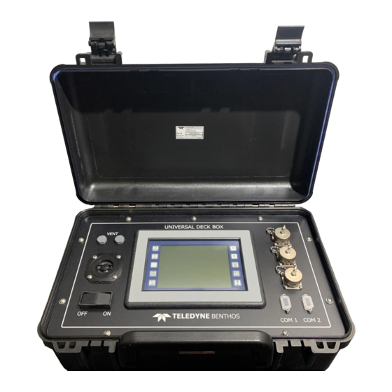
UDB-9000 Universal Deck Box - UDB-9000-M (Portable) and UDB-9000-MR (Rack Mount) Configurations UDB-9000-M and UDB-9000-MR Universal Deck Boxes The portable (UDB-9000-M) Universal Deck Box is contained in an impact resistant case with a splashproof front panel. The front panel includes a touch screen display, operator controls, connectors for making all the external connections, a speaker, and two vent plugs. -
Page 20: Aux Cable
TELEDYNE BENTHOS AUX Cable The AUX cable is optional. This cable enables the connection of headphones, external DC power and a transmit sync output. Accessories Case The accessories case contains the transducer, the transducer cable, the AC power cable, and the optional AUX cable. This manual is also included in the case for the rack mount configuration of the deck box only. -
Page 21: Operator Functions
UDB-9000 Universal Deck Box - UDB-9000-M (Portable) and UDB-9000-MR (Rack Mount) Configurations Operator Functions All of the UDB-9000 operator functions are provided on the front panel in both the portable and rack mount configurations. Operator Functions—Portable Configuration The operator functions for the portable configuration of the UDB-9000 are shown in Figure 1-2. -
Page 22: Operator Functions-Rack Mount Configuration
TELEDYNE BENTHOS Speaker: Provides an audio verification of transmitted and received data, pings and replies. Vent ports: Allow pressure relief from battery outgassing during charging without ingressing water. Operator Functions—Rack Mount Configuration The operator functions for the portable configuration of the UDB-9000 are shown in Figure 1-3. -
Page 23: Connections
UDB-9000 Universal Deck Box - UDB-9000-M (Portable) and UDB-9000-MR (Rack Mount) Configurations Connections All of the connections to the UDB-9000 are made on the front panel of the portable configuration and the rear panel of the rack mount configuration. Connections—Portable Configuration The connections to the portable configuration of the UDB-9000 are shown in Figure 1-2 on page 1-5. -
Page 24: Figure 1-4 Udb-9000 Rear Panel Connections-Rack Mount
TELEDYNE BENTHOS XDCR COM2 COM1 Figure 1-4 UDB-9000 Rear Panel Connections—Rack Mount Configuration AUX: 15-pin bulkhead connector—available for connection to headphones and to external 10–30 VDC power (optional). Also provides spare outputs and inputs and a transmit sync output. COM1: DB-9S connector—female serial port connector... -
Page 25: Specifications
UDB-9000 Universal Deck Box - UDB-9000-M (Portable) and UDB-9000-MR (Rack Mount) Configurations Specifications This section provides specifications for the UDB-9000 Universal Deck Box. All specifications are subject to change without notification. General Acoustic Telemetry Modem Frequency band: 9–14 kHz (LF), 16–21 kHz (MF), 25–30 kHz (HF), or 22–27 kHz (Band C) Data modulation: PSK and MFSK... -
Page 26: Environmental
TELEDYNE BENTHOS Environmental Temperature, operating: 14–140°F (-10°C–60°C) Temperature, nonoperating: -4–158°F (-20°C–70°C) Relative humidity, operating: 10–60% noncondensing Relative humidity, nonoperating: 100% for 72 hours w/temperature caused condensation; dry for operation Shock, operating: 3 G for 11, ±1 ms in all 3 axis Shock, nonoperating: 3 G for 11, ±1 ms in all 3 axis... -
Page 27: Rack Mount Configuration Physical Characteristics
UDB-9000 Universal Deck Box - UDB-9000-M (Portable) and UDB-9000-MR (Rack Mount) Configurations Rack Mount Configuration Physical Characteristics Case construction: Aluminum, clear anodized and painted Case type: 19-inch rack mount Dimensions: 26.7 cm (10.5 in.) high by 48.3 cm (19.0 in.) wide by 11.9 cm (4.7 in.) deep Weight: 5.5 kg (12 lb) -
Page 28: Input/Output
TELEDYNE BENTHOS Input/Output Operator functions: Power switch Touch screen display Displays and indicators: Touch screen display Speaker External connections: Power Transducer Auxiliary COM1 serial port COM2 serial port Transducer The available transducers are release band (LF), medium frequency (MF), high frequency (HF), and Band C. -
Page 29: Medium Frequency (Mf) Transducer
UDB-9000 Universal Deck Box - UDB-9000-M (Portable) and UDB-9000-MR (Rack Mount) Configurations Medium Frequency (MF) Transducer Transducer cable length: 25 m (82 ft) standard; 50 m (164 ft), 75 m (246 ft), 100 m (328 ft), or 200 m (656 ft) optional Frequency band: 16–21 kHz... -
Page 30: Band C Transducer
TELEDYNE BENTHOS Band C Transducer Transducer cable length: 25 m (82 ft) standard; 50 m (164 ft), 75 m (246 ft), 100 m (328 ft), or 200 m (656 ft) optional Frequency band: 22–27 kHz 183 (±6 dB) dB re 1 μPa @ 1m, typical... -
Page 31: Installation And Setup
The UDB-9000 is carefully packed in one or more sealed boxes, depending on the items ordered. Carefully inspect the boxes for any signs of external damage and immediately report any damage to Teledyne Benthos and to the freight carrier. After inspecting the boxes, locate and remove the packing list. -
Page 32: Figure 3-1 Udb-9000 Outline Dimensions-Portable
NOTE: Dimensions are in inches. Figure 3-1 UDB-9000 Outline Dimensions—Portable Configuration... -
Page 33: Figure 3-2 Udb-9000 Outline Dimensions-Rack Mount
NOTE: Dimensions are in inches. Figure 3-2 UDB-9000 Outline Dimensions—Rack Mount Configuration... -
Page 34: Connecting The Deck Box
TELEDYNE BENTHOS Connecting the Deck Box The portable configuration of the UDB-9000 requires only a transducer connection. However, to charge the batteries, the deck box must be connected to power. Refer to "Battery Maintenance and Charging" on page 6-2 for some charging recommendations. The rack mount configuration of the UDB-9000 must be connected to power and to the transducer. -
Page 35: Figure 3-3 Transducer Outline Dimensions
NOTE: Dimensions are in inches. NOTE: Dimensions are in inches. Figure 3-3 Transducer Outline Dimensions... -
Page 36: Figure 3-4 Pwr Connector
TELEDYNE BENTHOS To connect the deck box: 1. Connect the AC power source to the PWR connector using the AC power cable. For reference, refer to Figure 3-4 for the connector pin orientation, and to Table 3-1 for the pinout information. -
Page 37: Figure 3-6 Aux Connector
UDB-9000 Universal Deck Box - UDB-9000-M (Portable) and UDB-9000-MR (Rack Mount) Configurations 3. If using a headphone set, externally triggering the transmitter or connecting the binary inputs and outputs, make these connections using the AUX connector. An AUX cable is optionally available. Refer to Figure 3-6 for the connector pin orientation, and to Table 3-3 for the pinout information. -
Page 38: Figure 3-8 Com1 Connector
TELEDYNE BENTHOS 5. If sending and receiving acoustic telemetry modem commands and data, connect the serial port of a PC to the COM1 connector. Refer to Figure 3-8 for the connector pin orientation, and to Table 3-5 for the pinout information. -
Page 39: Operation Using The Touch Screen Display
Touch Screen Display This section provides instructions on how to use the touch screen display of the UDB-9000 Universal Deck Box to operate Teledyne Benthos acoustic transponders, releases and acoustic telemetry modems. Instructions are also provided on how to operate the deck box with EdgeTech/EG&G and URI releases. -
Page 40: Touch Screen Display Overview
In addition, from this screen a Compact Modem wakeup signal can be sent to activate the Teledyne Benthos compact acoustic telemetry modems. Transpond Data. Opens the Transpond Data screen where the received transponder reply frequencies, ranges and the round trip travel times are displayed for each transmitted ping. - Page 41 UDB-9000 Universal Deck Box - UDB-9000-M (Portable) and UDB-9000-MR (Rack Mount) Configurations RELEASE/RANGE SCREEN TRANSPOND DATA SCREEN MODEM COMMS SCREEN MODEM CONFIG SCREEN DISPLAY SCREEN Figure 4-2 UDB-9000 Touch Screen Main Screens Operation using the Touch Screen Display Touch Screen Display Overview...
-
Page 42: Save And Help Functions
TELEDYNE BENTHOS Modem Comms. Opens the Modem Comms screen where many of the functions of the Teledyne Benthos acoustic telemetry modems can be operated, including the wakeup of compact acoustic telemetry modems. Modem Config. Opens the Modem Config screen where the settings of the local and remote acoustic telemetry modems can be configured. -
Page 43: Status And Control Bar
UDB-9000 Universal Deck Box - UDB-9000-M (Portable) and UDB-9000-MR (Rack Mount) Configurations For Teledyne Benthos copyright and contact information, touch About. The About pop-up opens as shown in Figure 4-4. And for system information, touch System Info. The System Info pop-up opens which is also shown in Figure 4-4. -
Page 44: General Setup
TELEDYNE BENTHOS General Setup The general setup of the UDB-9000 involves selecting the modem address and transmit power level, adjusting the headphones and speaker volumes, setting the time and date, adjusting the touch screen display backlight and contrast, configuring the power saver and the serial ports, and selecting the audible beep and units preferences. -
Page 45: Selecting The Transmit Power Level
UDB-9000 Universal Deck Box - UDB-9000-M (Portable) and UDB-9000-MR (Rack Mount) Configurations Selecting the Transmit Power Level The transmit power level of the UDB-9000 can be selected by selecting an attenuation in decibels, or by selecting minimum for the lowest power (maximum attenuation) or maximum for the highest power (no attenuation). -
Page 46: Adjusting The Speaker Volume
TELEDYNE BENTHOS check will appear in the box. To turn the headphones back on, touch the box again. 3. Touch the check mark to close the Phones Vol pop-up and save the volume or mute setting. Adjusting the Speaker Volume The speaker volume can be adjusted or the speaker muted. -
Page 47: Figure 4-11 Set Time And Date Pop-Up
UDB-9000 Universal Deck Box - UDB-9000-M (Portable) and UDB-9000-MR (Rack Mount) Configurations 4. Tap, or touch and hold, the up or down arrow of the hours setting to set the hour. The hours setting is to the far left. 5. Tap, or touch and hold, the up or down arrow of the minutes setting to set the minute. -
Page 48: Viewing The Battery Level/Charge And External Ac/Dc Power Source Indicators
4-10 TELEDYNE BENTHOS Viewing the Battery Level/Charge and External AC/DC Power Source Indicators The Battery Level/Charge indicator provides an analog indication of the energy remaining in the two internal batteries. It also indicates when the batteries are being charged or if there are no batteries installed. The External AC/DC Power Source indicator indicates whether external AC or DC power is powering the UDB-9000. -
Page 49: Adjusting The Touch Screen Display Backlight And Contrast
Similarly, if the screen is not touched for a predetermined time, the displays will no longer be visible, but every ten seconds the Teledyne Benthos logo will appear for one second to indicate that the deck box is on. When the screen is touched, the displays will be visible again. -
Page 50: Configuring The Serial Ports
4-12 TELEDYNE BENTHOS To configure the power saver settings: 1. Touch the Display function button. The Display screen opens. 2. When in Save mode, the Screen mode button indicates Screen mode: Save. In Normal mode it indicates Screen mode: Normal. Touch the button repeatedly to select Save mode. -
Page 51: Figure 4-15 Com1 Configuration Pop-Up
UDB-9000 Universal Deck Box - UDB-9000-M (Portable) and UDB-9000-MR (Rack Mount) Configurations 4-13 3. Touch the Baud Rate setting and select the baud rate from the drop-down list box. 4. Touch the Data Bits setting and select 7 or 8 data bits. 5. -
Page 52: Selecting The Beep And Units Preferences
4-14 TELEDYNE BENTHOS 10. Touch the Flow Control setting and select Xon/Xoff, hardware or none. 11. Touch the Operation Mode setting and select Disabled, DS-7000 Deck Box Emulation or CLAM Shell pass-through. 12. Touch the check mark to close the COM2 Configuration pop-up and save the COM2 serial port settings. -
Page 53: Working With Information Windows
UDB-9000 Universal Deck Box - UDB-9000-M (Portable) and UDB-9000-MR (Rack Mount) Configurations 4-15 Working with Information Windows When using the UDB-9000 with Teledyne Benthos acoustic telemetry modems, SMART releases, SMART modems, and Compact Modems, information windows will occasionally open over the currently open screen in the touch screen display. -
Page 54: Waking Up A Compact Modem
4-16 TELEDYNE BENTHOS Waking up a Compact Modem The Teledyne Benthos Compact Modems function the same as all the other Teledyne Benthos manufactured acoustic telemetry modems, including SMART releases and SMART modems. However, because the Compact Modems are designed for long deployment, they are in a low power state most of the time. -
Page 55: Transmitting A Wakeup Signal To A
Modem The UDB-9000 can be used to acquire and display ranges to, and to acquire and display the status of, any Teledyne Benthos manufactured acoustic telemetry modem, including SMART releases and SMART modems. Before acquiring ranges or status, always ensure that the transducer is connected. -
Page 56: Acquiring And Displaying The Range To A
4-18 TELEDYNE BENTHOS NOTE Range can also be acquired and displayed in the Modem Comms screen. Refer to "Acquiring and Displaying Ranges in the Modem Comms Screen" on page 4-31. Acquiring and Displaying the Range to a Remote Modem To acquire and display the range to a remote modem: 1. -
Page 57: Figure 4-24 Transpond Parameters Pop-Up
UDB-9000 Universal Deck Box - UDB-9000-M (Portable) and UDB-9000-MR (Rack Mount) Configurations 4-19 NOTE The Range Options pop-up is also available on the Remote tabs of the Modem Comms and Modem Config screens where as many as three modem addresses can be entered, one on each tab. The ranges are displayed on the tabs in the Modem Config screen. -
Page 58: Acquiring And Displaying Ranges To A Remote Modem Continuously
4-20 TELEDYNE BENTHOS Acquiring and Displaying Ranges to a Remote Modem Continuously Ranges to a remote modem can be acquired continuously by sending the range command at the end of each timeout. To acquire and display ranges continuously, acquire and display ranges as described in "Acquiring and Displaying the Range to a Remote Modem"... -
Page 59: Releasing A Smart Release Or Modem
UDB-9000 Universal Deck Box - UDB-9000-M (Portable) and UDB-9000-MR (Rack Mount) Configurations 4-21 When the window closes, the status information is displayed in the Benthos Smart Release/ Modem pop-up along with the type of modem as shown in Figure 4-27. If the status information is not acquired, a no response indication is displayed in the window. -
Page 60: Figure 4-29 Released Confirmed-Smart Release
4-22 TELEDYNE BENTHOS The keypad closes and the release code is displayed as the Release Code or Burn Wire Code setting. WARNING Before proceeding with the next step, verify that the release code is correct. 5. Touch—and hold—Send. Three short beeps followed by a long beep will be heard, and then the Send button will become highlighted. -
Page 61: Configuring And Checking A Remote Modem
UDB-9000 Universal Deck Box - UDB-9000-M (Portable) and UDB-9000-MR (Rack Mount) Configurations 4-23 For a SMART modem, if the correct release code was received, the message "Burn wire ACTIVATED," should be displayed in the Benthos Smart Release/Modem pop-up as shown in Figure 4-30. Once the burn wire has fully burned, which may take several minutes, an alert window opens. -
Page 62: Configuring The Baud Rate And Transmit Power Level Of A Remote Modem
4-24 TELEDYNE BENTHOS 2. Touch the Remote A, Remote B or Remote C tab to open the tab. The tab label indicates the current remote modem address setting. The Remote A tab is shown in Figure 4-31 on page 4-23. -
Page 63: Checking The Baud Rate, Transmit Power Level And Firmware Version Of A Remote Modem
UDB-9000 Universal Deck Box - UDB-9000-M (Portable) and UDB-9000-MR (Rack Mount) Configurations 4-25 5. Touch Set Remote for remote transmit power level setting. An information window temporarily opens indicating that the remote modem settings are being updated. When complete, the update is confirmed, and then the Set Remote button becomes unavailable for that remote transmit power level selection only. -
Page 64: Checking The Battery Level Of A Remote Modem
4-26 TELEDYNE BENTHOS Checking the Battery Level of a Remote Modem To check the battery level of a remote modem: 1. Touch the tab in the Modem Config screen for the modem whose battery level is to be checked. 2. On the tab, touch Get Battery. -
Page 65: Testing The Acoustic Link With A Remote Modem
UDB-9000 Universal Deck Box - UDB-9000-M (Portable) and UDB-9000-MR (Rack Mount) Configurations 4-27 "Selecting the Beep and Units Preferences" on page 4-14 to select meters or feet for the range display. The same range information is also displayed on the tab. If the range is not acquired, a no response indication is displayed in the information window. -
Page 66: Communicating With A Remote Modem
4-28 TELEDYNE BENTHOS Table 4-1 PSNR Value and Required Action PSNR ACTION REQUIRED VALUE Signal quality is high. Can use a lower power level or higher acoustic baud rate. 19–25 Signal quality is good. Signal quality is acceptable. If multipath is a factor, a lower power level 14–12... -
Page 67: Sending Commands To An Instrument That Is Connected To A Remote Modem
UDB-9000 Universal Deck Box - UDB-9000-M (Portable) and UDB-9000-MR (Rack Mount) Configurations 4-29 The Remote A tab is shown in Figure 4-37 on page 4-28. 3. Touch the Address setting. The address keypad opens as shown in Figure 4-38. 4. Enter the remote modem address, two characters maximum, and then touch OK. -
Page 68: Figure 4-39 Keyboard
4-30 TELEDYNE BENTHOS 4. Touch Send Data. A keyboard opens as shown in Figure 4-39. Figure 4-39 Keyboard 5. Enter the command to be sent, a maximum of 50 characters, by touching the appropriate keys. The command is displayed immediately above the keyboard as shown in Figure 4-40. -
Page 69: Acquiring And Displaying Ranges In The Modem
UDB-9000 Universal Deck Box - UDB-9000-M (Portable) and UDB-9000-MR (Rack Mount) Configurations 4-31 7. Enter and send additional commands as required, and then touch Cancel to close the keyboard. 8. To clear the display, touch Clear. The Confirm Log Clear window opens as shown in Figure 4-42. -
Page 70: Receiving Messages From Remote Modems
4-32 TELEDYNE BENTHOS Receiving Messages from Remote Modems Messages can be received from any remote modem, and when received, they are displayed in the touch screen display—along with any ranges or sent messages—when the Modem Comms screen is open. Messages can be received regardless which screen is open at the time of receipt. -
Page 71: Clearing The Log File
2. Touch Clear Log. The log file cleared. Transponder Functions The UDB-9000 can be used to acquire and display ranges to any Teledyne Benthos manufactured acoustic transponder or release, and similarly, to those manufactured by EdgeTech/EG&G and URI, or to any transponder that replies to pings in the frequency range 7–16 kHz. -
Page 72: Figure 4-46 Release/Range Screen
4-34 TELEDYNE BENTHOS To make the transponder settings: 1. Touch the Release/Range function button. The Release/Range screen opens as shown in Figure 4-46. Figure 4-46 Release/Range Screen 2. Select the transponder type from the drop-down list. Selecting Benthos FSK opens the Benthos FSK pop-up as shown in Figure 4-47. -
Page 73: Figure 4-49 University Of Rhode Island Pop-Up
UDB-9000 Universal Deck Box - UDB-9000-M (Portable) and UDB-9000-MR (Rack Mount) Configurations 4-35 3. Touch Transpond Options to open the Transpond Options pop-up if it is not already open as shown. NOTE The Transpond Options pop-up is available in both the Transpond Data and Range/Release screens. -
Page 74: Figure 4-51 Advanced Transponder Parameters Pop-Up
4-36 TELEDYNE BENTHOS 7. Touch Advanced. The Advanced Transpond Parameters pop-up opens as shown in Figure 4-51. 8. Tap, or touch and hold, the up or down arrow to adjust the receive threshold. The receive threshold sets the number of standard deviations that... -
Page 75: Acquiring And Displaying Ranges
UDB-9000 Universal Deck Box - UDB-9000-M (Portable) and UDB-9000-MR (Rack Mount) Configurations 4-37 Acquiring and Displaying Ranges Within a single timeout, ranges to any number of transponders that have reply frequencies in the range 7–16 kHz, in 250-Hz increments, can be acquired, displayed and output on the COM2 serial port. -
Page 76: Figure 4-54 Transponder Filter Editing Pop-Up-Blocked
4-38 TELEDYNE BENTHOS If the frequency is hidden, tap the up or down arrow or drag the slider up or down to show it. To unblock a blocked frequency, select it again. Blocked frequencies are highlighted as shown in Figure 4-54. They are also shown with an "N."... -
Page 77: Acquiring And Displaying Ranges Continuously
UDB-9000 Universal Deck Box - UDB-9000-M (Portable) and UDB-9000-MR (Rack Mount) Configurations 4-39 the displayed frequencies versus range in kilometers also appear in the thumbnail graph. Tapping inside the graph changes the range scale. Four full scale ranges are available: 1, 5, 10, and 15 kilometers. If the Transpond Options pop-up is open and it is desired to display more ranges, touch Transpond... -
Page 78: Sending Commands To Acoustic Releases
Sending Commands to Teledyne Benthos Acoustic Releases In addition to release commands, for some Teledyne Benthos manufactured acoustic releases, transponder enable, disable and other commands can also be sent. However, the procedure to send all the commands is the same. -
Page 79: Figure 4-59 Command Code Keypad
UDB-9000 Universal Deck Box - UDB-9000-M (Portable) and UDB-9000-MR (Rack Mount) Configurations 4-41 4. Determine the command code for the transponder. It will be one of 13 letters, A through M. 5. Touch the Command setting. The command code keypad opens as shown in Figure 4-59. -
Page 80: Sending Commands To Edgetech/Eg&G Acoustic Releases
4-42 TELEDYNE BENTHOS The command is sent and the Transpond Data screen opens. With this screen open—and after the command has been transmitted and any acknowledgements received—ranges can be acquired and displayed by touching Transpond (Ping). In addition, touching Repeat before touching Transpond (Ping) enables continuous ranging on a released transponder for tracking purposes. -
Page 81: Figure 4-62 Edgetech/Eg&G Pop-Up
UDB-9000 Universal Deck Box - UDB-9000-M (Portable) and UDB-9000-MR (Rack Mount) Configurations 4-43 4. Using the up or down arrow for each digit, enter the release code. WARNING Before proceeding with the next step, verify that the release code is correct. 5. -
Page 82: Sending Commands To Uri Acoustic Releases
4-44 TELEDYNE BENTHOS Sending Commands to URI Acoustic Releases Release commands can be sent to URI manufactured acoustic releases. In addition, other transponder command functions, if available, can be operated as long as the same type of command coding scheme is used. - Page 83 UDB-9000 Universal Deck Box - UDB-9000-M (Portable) and UDB-9000-MR (Rack Mount) Configurations 4-45 6. Release Send. The command is sent and the Transpond Data screen opens. With this screen open—and after the command has been transmitted and any acknowledgements received—ranges can be acquired and displayed by touching Transpond (Ping).
-
Page 85: Operation Using Serial Interface Commands
UDB-9000 Universal Deck Box - UDB-9000-M (Portable) and UDB-9000-MR (Rack Mount) Configurations Operation using Serial Interface Commands This section provides instructions on how to send commands to the UDB-9000 Universal Deck Box and receive round trip travel times and status information using the same command set and syntax as that used for the DS-7000 Acoustic Deck Set. -
Page 86: Sending Commands And Receiving Data
TELEDYNE BENTHOS Flow Control: None Operation mode: DS-7000 Deck Box Emulation Sending Commands and Receiving Data For commands to be sent and for round trip travel times and status information to be received, the UDB-9000 must be on and an "@" prompt must be displayed on the monitor of the PC. -
Page 87: Table 5-1 Ds-7000 Read Commands
Table 5-1 DS-7000 Read Commands COMMAND NAME MNEMONIC RESPONSE Receive Pulse Duration RD=#.## where x is 6.25 or 12.50 in ms Receive Sensitivity RS=### where ### is 010 to 256 in standard deviations over average noise level Version Information VE=s.s f.f where s.s is the display software version and f.f is the modem firmware ver- sion Date DA=mm/dd/yy... - Page 88 Table 5-1 DS-7000 Read Commands (Continued) COMMAND NAME MNEMONIC RESPONSE List Ping Responses RT=## rx.ff xxx.xxxx for each ping in the buffer where ## is the ping identifier, rx.ff is the receive frequency, and xxx.xxxx is the reply time. ## will be 00 if no identifier was specified.
-
Page 89: Table 5-2 Ds-7000 Write Commands
Table 5-2 DS-7000 Write Commands COMMAND NAME SYNTAX RESPONSE Receive Pulse Duration RD #.## or RD=#.## RD= #.## where x is 6.25 or 12.5 in milliseconds Receive Sensitivity RS ### or RS=### RS=### where ### is 010 to 500 Date DA mm/dd/yy or DA=mm/dd/yy DA=mm/dd/yy Time... - Page 90 Table 5-2 DS-7000 Write Commands (Continued) COMMAND NAME SYNTAX RESPONSE Frequency Add FA ##.## … ##.## or FA=##.## … ##.## FA=##.## … ##.## where ##.## is 07.00 to 15.00 in .25 increments Frequency Delete FD ##.## … ##.## or FD=##.## … ##.## FD=##.## …...
-
Page 91: Care And Maintenance
UDB-9000 Universal Deck Box - UDB-9000-M (Portable) and UDB-9000-MR (Rack Mount) Configurations Care and Maintenance This section includes the recommended care and maintenance procedures for the UDB-9000 Universal Deck Box. Adherence to these recommendations will help to ensure years of continuous, reliable performance. -
Page 92: Battery Maintenance And Charging
TELEDYNE BENTHOS Battery Maintenance and Charging Depending on use, the life of the batteries in the UDB-9000 is typically two to five years. To prolong their life when storing of the UDB-9000, the deck box should be stored at a temperature of 50°F (10° C) or less. The batteries should also be charged when not in use. -
Page 93: Figure 6-2 Lifting The Edge Of The Front Panel
UDB-9000 Universal Deck Box - UDB-9000-M (Portable) and UDB-9000-MR (Rack Mount) Configurations 2. Grasp one of the connectors on the right side of the front panel, and then gently lift the edge of the panel away from the case as shown in Figure 6-2. -
Page 94: Figure 6-4 Loosening The Battery Bracket Screws
TELEDYNE BENTHOS 4. Set the electronics chassis on its side and slightly loosen—but do not remove— the battery bracket screws, three screws for each bracket, as shown in Figure 6-4. BATTERY BRACKET SCREWS (6) ELECTRONICS CHASSIS Figure 6-4 Loosening the Battery Bracket Screws 5. -
Page 95: Figure 6-6 Disconnecting The Battery
UDB-9000 Universal Deck Box - UDB-9000-M (Portable) and UDB-9000-MR (Rack Mount) Configurations 8. One at a time, slide each battery part way into the electronics chassis and connect the wires to the battery terminals. For the battery on the left side of the deck box, which is the one shown in Figure 6-6, connect... -
Page 96: Figure 6-8 Lowering The Electronics Chassis Into The Case
TELEDYNE BENTHOS 11. Carefully lower the electronics chassis into the case, being careful to ensure the battery brackets clear the inside rim as shown in Figure 6-8. 12. Install and securely tighten the 10 front panel screws. CASE Figure 6-8 Lowering the Electronics Chassis into the Case User’s Manual... -
Page 97: Calibrating The Touch Screen Display
UDB-9000 Universal Deck Box - UDB-9000-M (Portable) and UDB-9000-MR (Rack Mount) Configurations Calibrating the Touch Screen Display If when touching a control, it does not respond, the touch screen display may require calibration. To calibrate the touch screen display: NOTE If the UDB-9000 is currently turned off, touch and hold in the lower right corner of the screen while turning the deck box on.
Need help?
Do you have a question about the BENTHOS UDB-9000 and is the answer not in the manual?
Questions and answers