Table of Contents
Advertisement
Thermal Conductivity Analyzer
OPERATING INSTRUCTIONS FOR
Model 2000A-EU
Thermal Conductivity Analyzer
DANGER
HIGHLY TOXIC AND OR FLAMMABLE LIQUIDS OR GASES MAY BE PRESENT IN THIS MONITORING
SYSTEM.
PERSONAL PROTECTIVE EQUIPMENT MAY BE REQUIRED WHEN SERVICING THIS SYSTEM.
HAZARDOUS VOLTAGES EXIST ON CERTAIN COMPONENTS INTERNALLY WHICH MAY PERSIST
P/N M66182
FOR A TIME EVEN AFTER THE POWER IS TURNED OFF AND DISCONNECTED.
07/22/05
ONLY AUTHORIZED PERSONNEL SHOULD CONDUCT MAINTENANCE AND/OR SERVICING. BEFORE
ECO # 05-0131
CONDUCTING ANY MAINTENANCE OR SERVICING CONSULT WITH AUTHORIZED SUPERVISOR/
MANAGER.
i
Teledyne Analytical Instruments
Advertisement
Table of Contents

Related Manuals for Teledyne 2000A-EU


Summary of Contents for Teledyne 2000A-EU
-
Page 1: Teledyne Analytical Instruments
Thermal Conductivity Analyzer OPERATING INSTRUCTIONS FOR Model 2000A-EU Thermal Conductivity Analyzer DANGER HIGHLY TOXIC AND OR FLAMMABLE LIQUIDS OR GASES MAY BE PRESENT IN THIS MONITORING SYSTEM. PERSONAL PROTECTIVE EQUIPMENT MAY BE REQUIRED WHEN SERVICING THIS SYSTEM. HAZARDOUS VOLTAGES EXIST ON CERTAIN COMPONENTS INTERNALLY WHICH MAY PERSIST P/N M66182 FOR A TIME EVEN AFTER THE POWER IS TURNED OFF AND DISCONNECTED. - Page 2 Any safeguards required such as locks, labels, or redun- dancy, must be provided by the user or specifically requested of Teledyne at the time the order is placed.
- Page 3 Thermal Conductivity Analyzer Specific Model Information The instrument for which this manual was supplied may incorporate one or more options not supplied in the standard instrument. Commonly available options are listed below, with check boxes. Any that are incorporated in the instrument for which this manual is supplied are indicated by a check mark in the box.
- Page 4 Model 2000A-EU Model 2000A-EU complies with all of the requirements of the Commonwealth of Europe (CE) for Radio Frequency Interference, Electromagnetic Interference (RFI/EMI), and Low Voltage Directive (LVD). The following International Symbols are used throughout the In- struction Manual for your visual and immediate warnings and when...
-
Page 5: Table Of Contents
Thermal Conductivity Analyzer Table of Contents 1 Introduction 1.1 Overview ................ 1-1 1.2 Typical Applications ............1-2 1.3 Main Features of the Analyzer ........1-2 1.4 Model Designations ............1-3 1.5 Front Panel (Operator Interface) ........1-3 1.6 Recognizing Difference Between LCD & VFD ....1-5 1.7 Rear Panel (Equipment Interface) ........ - Page 6 Model 2000A-EU 3.4.5 REFERENCE Gas ..........3-15 3.4.6 ZERO Gas ............. 3-15 3.4.7 SPAN Gas .............. 3-15 3.5 Testing the System ............3-16 3.6 Warm Up at Power Up ............ 3-16 4 Operation 4.1 Introduction ..............4-1 4.2 Using the Data Entry and Function Buttons ....4-1 4.3 The System Function .............
- Page 7 Thermal Conductivity Analyzer 4.9.2 Special - Inverting Output ........4-29 4.9.3 Special - Polarity Coding ........4.29 4.9.4 Special - Nonlinear Application Gain Preset..4-29 Maintenance 5.1 Routine Maintenance ............. 5-1 5.2 System Self Diagnostic Test ........... 5-1 5.3 VFD Display ..............5-2 5.4 Fuse Replacement............
- Page 8 Model 2000A-EU viii...
-
Page 9: Introduction
2000A-EU Analyzer complies with all of the requirements of the Comonwealth of Europe (CE) for Radio Frequency Interference and Elec- tromagnetic Interfaces (RFI/EMI) protection. -
Page 10: Typical Applications
1 Introduction Model 2000A-EU Typical Applications A few typical applications of the Model 2000 are: • Power Generation • Air liquefaction • Chemical reaction monitoring • Steel manufacturing and heat treating • Petrochemical process control • Quality assurance • Refrigeration and storage •... -
Page 11: Model Designations
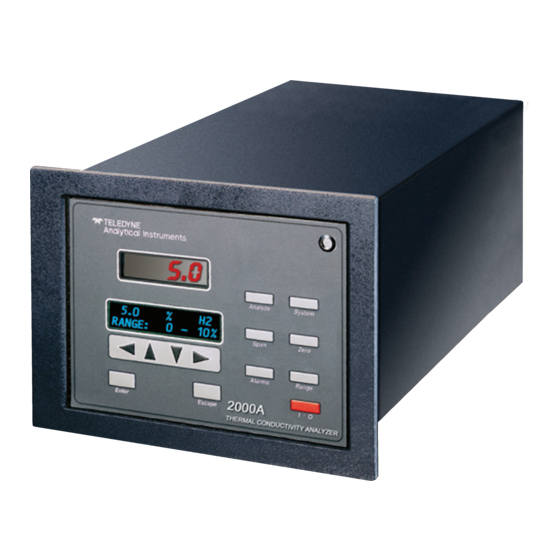
Compact and versatile design: Small footprint, yet internal components are accessible. Model Designations The Model 2000A-EU is ordinarily custom programmed at the factory to fit the customer’s application. Many parameters, including the number of channels, the gas application, the materials specification of the sampling system, and others, are options. - Page 12 1 Introduction Model 2000A-EU Figure 1-1: Model 2000A Front Panel • System Perform system-related tasks (described in detail in chapter 4, Operation.). • Span Span calibrate the analyzer. • Zero Zero calibrate the analyzer. • Alarms Set the alarm setpoints and attributes.
-
Page 13: Recognizing Difference Between Lcd & Vfd
DARK background with GREEN characters. In the case of VFD - NO CONTRAST ADJUSTMENT IS NEEDED. Rear Panel (Equipment Interface) All electrical inputs and outputs to the 2000A are made through rear- panel connectors. The connectors are described briefly here and in detail in chapter 3, Installation. Teledyne Analytical Instruments... - Page 14 1 Introduction Model 2000A-EU Figure 1-2: Model 2000A-EU Rear Panel • Power Connection Universal AC power source. • 9-Pin RS-232 Port Serial digital concentration signal output and control input. • 50-Pin Equipment Interface Port • Analog Outputs 0-1 V dc concentration plus 0-1 V dc range ID, and isolated 4-20 mA dc plus 4-20 mA dc range ID.
-
Page 15: Gas Connections
Model 2000 series analyzer below the front panel. For those customers wishing to incorporate their own sample controls, the recommended system piping schematic is included among the drawings at the rear of the manual. Teledyne Analytical Instruments... - Page 16 1 Introduction Model 2000A-EU Teledyne Analytical Instruments...
-
Page 17: Operational Theory
The resistance of the filaments depends on their temperature. These filaments are parts of the two legs of a Wheatstone bridge circuit that unbalances if the resistances of its two legs do not match. See Figure 2-1(b). Teledyne Analytical Instruments... -
Page 18: Calibration
2 Operational Theory Model 2000A-EU Figure 2-1: Thermal Conductivity Cell Operating Principle If the thermal conductivities of the gases in the two chambers are different, the Wheatstone bridge circuit unbalances, causing a current to flow in its detector circuit. The amount of this current can be an indication... -
Page 19: Effects Of Flowrate And Gas Density
The Temperature Control board is mounted on the inner face of the rear panel, under the power input receptacle. The signal processing elec- tronics including the microprocessor, analog to digital, and digital to analog converters are located on the Motherboard at the bottom of the case. Teledyne Analytical Instruments... - Page 20 2 Operational Theory Model 2000A-EU The Preamplifier board is mounted on top of the Motherboard as shown in the figure (in chapter 5). These boards are accessible after removing the back panel. Figure 2-2 is a block diagram of the Analyzer electronics.
-
Page 21: Temperature Control
CPU. These, and all of the above electrical interface signals are described in detail in chapter 3 Installation. 2.4. Temperature Control For accurate analysis the sensor of this instrument is temperature controlled to 60 Teledyne Analytical Instruments... - Page 22 2 Operational Theory Model 2000A-EU Teledyne Analytical Instruments...
-
Page 23: Installation
The standard model is designed for flush panel mounting. Figure 3-1 is an illustration of the 2000A standard front panel and mounting bezel. There Teledyne Analytical Instruments... - Page 24 3 Installation Model 2000A-EU are four mounting holes—one in each corner of the rigid frame. Figure 3-1a contains the hole pattern dimensions. See the outline drawing, at the back of this manual for overall dimensions. On special order, a 19" rack-mounting panel can be provided. For rack mounting, one or two 2000A series analyzers are flush-panel mounted on the rack panel.
-
Page 25: Electrical Connections (Rear Panel)
90-degree arc of radius 19.3 cm. See Figure 3-2. Figure 3-2: Required Front Door Clearance Electrical Connections (Rear Panel) Figure 3-3 shows the Model 2000A-EU rear panel. There are connec- tors for power, digital communications, and both digital and analog con- centration output. -
Page 26: Primary Input Power
3 Installation Model 2000A-EU For safe connections, no uninsulated wiring should be able to come in contact with fingers, tools or clothing during normal operation. CAUTION: Use Shielded Cables. Also, use plugs that provide excellent EMI/RFI protection. The plug case must... -
Page 27: Analog Outputs
To relate the signal output to the actual concentration, it is necessary to know what range the instrument is currently on, especially when the analyzer is in the autoranging mode. Teledyne Analytical Instruments... -
Page 28: Alarm Relays
3 Installation Model 2000A-EU The signal output for concentration is linear over the currently se- lected analysis range. For example, if the analyzer is set on a range that was defined as 0–10 % hydrogen, then the output would be as shown in Table 3-2. -
Page 29: Digital Remote Cal Inputs
37 System Alarm, normally open contact 3.3.3.3 Digital Remote Cal Inputs Accept 0 V (off) or 24 V dc (on) inputs for remote control of calibra- tion. (See Remote Calibration Protocol below.) See Table 3-5 for pin connections. Teledyne Analytical Instruments... - Page 30 3 Installation Model 2000A-EU Zero: Floating input. A 5 to 24 V pulse input across the + and – pins puts the analyzer into the Zero mode. Either side may be grounded at the source of the signal. A synchronous signal must open and close the gas control valves appropri- ately.
-
Page 31: Range Id Relays
Pins 13 (+) and 29 (–). 3.3.3.6 Remote Valve Connector The 2000A is a single-chassis instrument, which has no Remote Probe Unit. Instead, the Remote Valve connector is used as another method for controlling external sample/zero/span gas valves. See Figure 3-5. Teledyne Analytical Instruments... -
Page 32: Rs-232 Port
3 Installation Model 2000A-EU Figure 3-5: Remote Probe Connector Pinouts The voltage from these outputs is nominally 0 V for the OFF and 15 V dc for the ON conditions. The maximum combined current that can be pulled from these output lines is 100 mA. (If two lines are ON at the same time, each must be limited to 50 mA, etc.) If more current and/or a... -
Page 33: Gas Connections
There are no gas control valves inside the main chassis. A sample system must be provided for introduction of zero and span gas, as well as sample gas, into the sample path, and for controlling the flowrates through the sample and reference paths of the analyzer. 3-11 Teledyne Analytical Instruments... - Page 34 3 Installation Model 2000A-EU Figure 3-8: Gas Connections to the Basic Unit If you have purchased a gas control panel from Analytical Instru- ments, the drawings at the back of this manual will contain a dimension outline drawing, with the modified cutout and hole pattern for mounting, and a drawing and/or addendum showing the gas connections.
-
Page 35: Sample System Design
Values can range from one half to twice the indicated flowrate. For example: For hydrogen or helium, set the flowrate to 50 cc/min (0.1 scfh). For carbon dioxide or argon, set the flow- rate to 200 cc/min (0.4 scfh). 3-13 Teledyne Analytical Instruments... -
Page 36: Vent Exhaust
3 Installation Model 2000A-EU When installing pressure regulators on supply cylinders, crack the cylinder valves so that gas is flowing during installation. This will elimi- nate the most common cause of standardization-gas contamination: air trapped during assembly diffusing back into the cylinder. This procedure is particularly important in applications where impurity content of 1 to 2 % is the range of interest. -
Page 37: Reference Gas
100 % of the component of interest is required as a minimum. If lineariza- tion is required, intermediate concentrations of the target gas in the back- ground gas may be necessary. From one to nine separate span gases may be 3-15 Teledyne Analytical Instruments... -
Page 38: Testing The System
3 Installation Model 2000A-EU used, depending on the desired precision of the linearization. See chapter 4, Operation. Testing the System Before plugging the instrument into the power source: • Check the integrity and accuracy of the gas connections. Make sure there are no leaks. -
Page 39: Operation
Data Entry Buttons: The < > buttons select options from the menu currently being displayed on the VFD screen. The selected option blinks. When the selected option includes a modifiable item, the arrow buttons can be used to increment or decrement that modifiable item. Teledyne Analytical Instruments... - Page 40 4 Operation Model 2000A-EU The Enter button is used to accept any new entries on the VFD screen. The Escape button is used to abort any new entries on the VFD screen that are not yet accepted by use of the Enter button.
- Page 41 Thermal Conductivity Analyzer Operation 4 System Contrast Function is DISABLED (Refer to Section 1.6) Enter Enter Enter Span Zero Alarms Range Analyze Figure 4-1: Hierarchy of Functions and Subfunctions Teledyne Analytical Instruments...
-
Page 42: The System Function
4 Operation Model 2000A-EU the appropriate point in the procedure, in a type style. Pushbut- ton names are printed in Oblique type. The System Function The subfuctions of the System function are described below. Specific procedures for their use follow the descriptions: •... -
Page 43: Setting The Display
Choose System from the Function buttons. The VFD will display five subfunctions. Contrast Function is DISABLED (Refer to Section 1.6) , and press Enter . A new screen Use < > arrows to blink set appears. Teledyne Analytical Instruments... -
Page 44: Password Protection
4 Operation Model 2000A-EU ), then press Enter again. (You Press < > arrows to blink won’t be able to set OFF to ON if a zero interval is entered.) A ... (or ...) screen appears. arrows to set an interval value, then use < > arrows to move to the start-time value. -
Page 45: Installing Or Changing The Password
Press Enter to change the password (either the default or the previ- ously assigned password), or press Escape to keep the existing password and move on. If you chose Enter to change the password, the password assignment screen appears. Teledyne Analytical Instruments... - Page 46 4 Operation Model 2000A-EU Enter the password using the < > arrow keys to move back and forth between the existing password letters, and the arrow keys to change the letters to the new password. The full set of 94 characters available for password use are shown in the table below.
-
Page 47: Logging Out
Use the < > arrow keys to blink Use the < > arrow keys again to move the blinking to the and press Enter. The screen will follow the running of the diagnostic. When the testing is complete, the results are displayed. Teledyne Analytical Instruments... -
Page 48: The Model Screen
4 Operation Model 2000A-EU The module is functioning properly if it is followed by . A number indicates a problem in a specific area of the instrument. Refer to Chapter 5 Maintenance and Troubleshooting for number-code information. The results screen alternates for a time with: Then the analyzer returns to the initial System screen. -
Page 49: The Zero And Span Functions
The analyzer is calibrated using reference, zero, and span gases. Gas requirements are covered in detail in chapter 3, section 3.4 Gas Connections. Check that calibration gases are connected to the analyzer according to the instructions in section 3.4, observing all the prescribed precautions. Teledyne Analytical Instruments 4-11... -
Page 50: Zero Cal
4 Operation Model 2000A-EU Note: Shut off the gas pressure before connecting it to the analyzer, and be sure to limit pressure to 40 psig or less when turning it back on. Readjust the gas pressure into the analyzer until the flowrate through the sensor settles between 50 to 200 cc/min (approximately 0.1 to 0.4 scfh). -
Page 51: Manual Mode Zeroing
(ppm/s). Note: It takes several seconds for the true Slope value to display. Wait about 10 seconds. Then, wait until Slope is sufficiently close to zero before pressing Enter to finish zeroing. Teledyne Analytical Instruments 4-13... -
Page 52: Cell Failure
4 Operation Model 2000A-EU Generally, you have a good zero when is less than 0.05 ppm/s for about 30 seconds. Once zero settling completes, the information is stored in the analyzer’s memory, and the instrument automatically returns to the Analyze mode. -
Page 53: Manual Mode Spanning
When you have set the concentration of the span gas you are using, press Enter to begin the Span calibration. Press Enter to enter the span value into the system and begin the span calibration. Teledyne Analytical Instruments 4-15... -
Page 54: The Alarms Function
4 Operation Model 2000A-EU Once the span has begun, the microprocessor samples the output at a predetermined rate. It calculates the difference between successive samplings and displays this difference as Slope on the screen. It takes several seconds for the first Slope value to display. Slope indicates rate of change of the Span reading. - Page 55 Press enter again to set the alarm setpoints. keys to choose between % and ppm units. Then press Enter Use the to move to the next screen. Five parameters can be changed on this screen: Teledyne Analytical Instruments 4-17...
-
Page 56: The Range Function
4 Operation Model 2000A-EU • Value of the alarm setpoint, AL–1 #### • Out-of-range direction, HI or LO • Defeated? Dft:Y/N (Yes/No) • Failsafe? Fs:Y/N (Yes/No) • Latching? Ltch:Y/N (Yes/No). • To define the setpoint, use the < > arrow keys to move the blinking over to AL–1 ####. -
Page 57: Manual (Select/Define Range) Screen
If the concentration falls to below 85% of full scale of the next lower range, the instrument switches to the lower range. A correspond- ing shift in the DC concentration output, and in the range ID outputs, will be noticed. Teledyne Analytical Instruments 4-19... -
Page 58: Precautions
4 Operation Model 2000A-EU The autoranging feature can be overridden so that analog output stays on a fixed range regardless of the contaminant concentration detected. If the concen- tration exceeds the upper limit of the range, the DC output will saturate at 1 V dc (20 mA at the current output). -
Page 59: The Analyze Function
Alternatively, you can press the Analyze button at any time to return to analyzing your sample. The Analyze function screen shows the impurity concentration and the application gases in the first line, and the range in the second line. In the lower Teledyne Analytical Instruments 4-21... -
Page 60: Programming
4 Operation Model 2000A-EU indicates that the analyzer is in the Analyze right corner, the abbreviation mode. If there is an * before the , it indicates that the range is linearized. If the concentration detected is overrange, the first line of the display blinks continuously. -
Page 61: The Set Range Screen
UNLESS the application uses linearization over the selected range. To program the ranges, you must first perform the four steps indicated at the beginning of section 4.8 Programming. You will then be in the second System menu screen. Teledyne Analytical Instruments 4-23... -
Page 62: The Curve Algorithm Screen
4 Operation Model 2000A-EU Use the < > arrow keys again to move the blinking to press Enter . Use the arrow keys to increment/decrement the range number to 0, 1, 2, or 3, and press Enter . Use the < > arrow keys to move to Imp: (impurity), Bck: (background), FR: (from—lower end of range), TO: (to—upper end of range), and PPM or %. -
Page 63: Checking The Linearization
It should be the ACTU- AL concentration of the span gas being simulated. If the value shown is not correct, the linearization must be corrected. Press ESCAPE to return to the previous screen. Select and EN- to Calibration Mode screen. Teledyne Analytical Instruments 4-25... -
Page 64: Manual Mode Linearization
4 Operation Model 2000A-EU There are two ways to linearize: : The auto mode requires as many calibration gases as there will be correction points along the curve. The user decides on the number of points, based on the precision re- quired. -
Page 65: Auto Mode Linearization
6. Repeat step 5 for each of the special calibration gases, from the lowest to the highest concentrations. Press Escape when done. To end the session: If started with the RS-232, send: Teledyne Analytical Instruments 4-27... -
Page 66: Special Function Setup
4 Operation Model 2000A-EU st<enter> st<enter> to the analyzer from the computer. If started through the front panel, turn the instrument off and back on. Press the Enter key twice to return to the Analyze mode. 4.9 Special Function Setup 4.9.1 Output Signal Reversal... -
Page 67: Special - Polarity Coding
Press SPAN key. Select AUTO mode and setup the setting to span level. Press ENTER key to span. Set range switch to next range. Press SPAN key. Teledyne Analytical Instruments 4-29... - Page 68 4 Operation Model 2000A-EU Press and hold the RIGHT key for approximate 5 to 7 seconds. Select AUTO and set the reading to span gas level. Press ENTER key. Repeat steps 1 to 7 if more than two ranges need to be setup.
-
Page 69: Maintenance
3. Use the < > arrow keys to move to The following failure codes apply: Table 5-1: Self Test Failure Codes Power 5 V Failure 15 V Failure Both Failed Analog DAC A (0–1 V Concentration) DAC B (0–1 V Range ID) Both Failed (Continued) Teledyne Analytical Instruments... -
Page 70: Vfd Display
5 Maintenance Model 2000A-EU Preamp Zero too high Amplifier output doesn't match test input Both Failed Cell Failed (open filament, short to ground, no power.) Unbalance (deterioration of filaments, blocked tube) VFD Display NOTE: Vaccum Fluorescent Display is used. It does not need contrast adjustment. -
Page 71: Major Internal Components
The 2000A contains the following major components: • Analysis Section Cell Compartment Cell Block • Power Supply • Preamp and Motherboard with Microcontroller • Display Board and Displays 5 digit LED meter 2 line, 20 character, alphanumeric, VFD display • Rear Panel Board. Teledyne Analytical Instruments... - Page 72 5 Maintenance Model 2000A-EU Figure 5-3: Rear Panel Retaining Screws To detach the rear panel, remove only those screws marked with an X. Figure 5-4: Locations of Printed Circuit Board Assemblies See the drawings in the Drawings section in back of this manual for details.
-
Page 73: Cell, Heater, And/Or Thermistor Replacement
WARNING: DISCONNECT ALL POWER TO THE MODEL 2000 BEFORE PERFORMING THIS PROCEDURE. FAIL- URE TO DO SO, MAY CAUSE ELECTRIC SHOCK. Figure 5-5: Location of Cell Compartment Retaining Screws To remove the Cell Compartment: a. Disconnect gas and electrical connections to the analyzer. Teledyne Analytical Instruments... -
Page 74: Removing And Replacing The Cell Block
5 Maintenance Model 2000A-EU b. Remove analyzer from its mounting, and remove gas fittings from the gas ports on the bottom of the analyzer, so that nothing projects from the ports. c. Remove the Cell Compartment retaining screws identified in Figure 5-5. -
Page 75: Removing The Heater And/Or Thermocouple
Cell Block Cover to the Cell Block—and then pull off the cover. c. Turn the uncovered Cell Block assembly over so that the bottom faces you. The black rectangular block with four screws is the Heater Block. Teledyne Analytical Instruments... -
Page 76: Cleaning
5 Maintenance Model 2000A-EU d. The Heater is fastened to the Heater Block by a set screw as well as the silicone sealing compound. The Thermistor is fastened only by the silicone sealer. (1) To remove the Heater, use a Allen wrench to loosen the Thermistor set screw. -
Page 77: Phone Numbers
Clean the front panel as prescribed in the above paragraph. Phone Numbers Customer Service: (626) 934-1673 Environmental Health and Safety: (626) 961-9221, Extension 230 Fax: (626) 961-2538 TWX: (910) 584-1887 TDYANYL COID EMERGENCY ONLY: (24-hour pager) 1-800-759-7243 PIN # 1858192 Teledyne Analytical Instruments... - Page 78 5 Maintenance Model 2000A-EU 5-10 Teledyne Analytical Instruments...
-
Page 79: Appendix A-1 Specifications
Two 4-20 mADC isolated (concentration and range ID) Alarm: Two fully programmable concentration alarm set points and corresponding Form C, 3 amp contacts. One system failure alarm contact to detect power, calibration, zero / span and sensor failure. Teledyne Analytical Instruments... - Page 80 Appendix Models 2000A-EU System Power Requirements: 110 VAC, 50-60Hz Dimensions: 7.5”H x 10.8 “w X 13.7”D Cell Material: Nickel plated brass block with nickel alloy filaments and stainless steel plates O/P Interface: Full duplex RS-232, implement a subset of Tracs Command...
-
Page 81: Recommended 2-Year Spare Parts List
Note: Orders for replacement parts should include the part number (if available) and the model and serial number of the instrument for which the parts are intended. Orders should be sent to: TELEDYNE Analytical Instruments 16830 Chestnut Street City of Industry, CA 91749-1580 Phone (626) 961-9221, Fax (626) 961-2538 TWX (910) 584-1887 TDYANYL COID or your local representative. - Page 82 Appendix Models 2000A-EU CALIBRATION PROCEDURE FOR Models 2000 & 2010 ANALYZER For TURBINE GENERATOR APPLICATION The ranges for this analyzer are: Range 1: 0-100% Air in CO2 Range 2: 0-100% H2 in CO2 Range 3: 80-100% H2 in Air Cal Range: 0-20% N2-H2 The following instructions show how to calibrate each range in the analyzer independently.
- Page 83 Enter. Now the analyzer will do the final step which is the Software zero adjustment. No input is required and the analyzer will return automatically to the Analyze mode when done. Teledyne Analytical Instruments...
- Page 84 Appendix Models 2000A-EU When the analyzer finishes the zero, feed the span gas and purge for the time needed to get readings that are leveled. Feed H2 to the analyzer. Press the SPAN button, press the arrow > hold it until OK appears on the upper right of the VFD display.
- Page 85 Enter. Now do the Fine zero adjustment using the Up and Down button until the display reads as close to zero as possible then press Enter. Now the analyzer will do the final step which is the Software zero adjustment. Teledyne Analytical Instruments...
- Page 86 Appendix Models 2000A-EU Now the analyzer will do the final step which is the Software zero adjustment. No input is required and the analyzer will return automatically to the Analyze mode when done. When the analyzer finishes the zero, feed the span gas and purge for the time needed to get readings that are leveled.
Need help?
Do you have a question about the 2000A-EU and is the answer not in the manual?
Questions and answers