Sign In
Upload
Manuals
Brands
Teledyne Manuals
Measuring Instruments
BENTHOS UDB-9000
Teledyne BENTHOS UDB-9000 Manuals
Manuals and User Guides for Teledyne BENTHOS UDB-9000. We have
1
Teledyne BENTHOS UDB-9000 manual available for free PDF download: User Manual
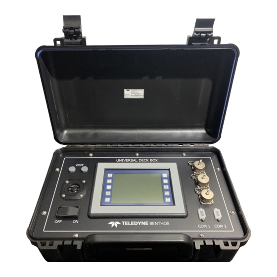
Teledyne BENTHOS UDB-9000 User Manual (98 pages)
Universal Deck Box
Brand:
Teledyne
| Category:
Measuring Instruments
| Size: 1.83 MB
Table of Contents
Notices
2
Liability
4
Title
4
Changes
4
Preface
5
Notes and Warnings
6
Customer Service
6
Table of Contents
7
List of Figures
11
Overview
17
Figure 1-1 the UDB-9000 Universal Deck Box-Portable and Rack Mount Configurations
17
General Description
18
UDB-9000-M and UDB-9000-MR Universal
19
Deck Boxes
19
Transducer
19
Transducer Cable
19
AUX Cable
20
Accessories Case
20
Operation
20
Power Requirements
20
External Connections
20
Operator Functions
21
Operator Functions-Portable Configuration
21
Figure 1-2 UDB-9000 Operator Functions and Connections-Portable Configuration
21
Operator Functions-Rack Mount Configuration
22
Figure 1-3 UDB-9000 Operator Functions-Rack Mount
22
Connections
23
Connections-Portable Configuration
23
Connections-Rack Mount Configuration
23
Figure 1-4 UDB-9000 Rear Panel Connections-Rack Mount
24
Specifications
25
General
25
Acoustic Telemetry Modem
25
Transponder
25
Environmental
26
Physical Characteristics
26
Portable Configuration Physical
26
Characteristics
26
Rack Mount Configuration Physical Characteristics
27
Power Requirements
27
Portable Configuration Power
27
Requirements
27
Rack Mount Configuration Power
27
Input/Output
28
Transducer
28
Lf/Release Band Transducer
28
Medium Frequency (MF) Transducer
29
Hi Frequency (HF) Transducer
29
Band C Transducer
30
Installation and Setup
31
Unpacking and Inspection
31
Setting up the Deck Box-Portable Configuration
31
Setting up the Deck Box-Rack Mount Configuration
31
Figure 3-1 UDB-9000 Outline Dimensions-Portable
32
Figure 3-2 UDB-9000 Outline Dimensions-Rack Mount
33
Connecting the Deck Box
34
Deploying the Transducer
34
Figure 3-3 Transducer Outline Dimensions
35
Figure 3-4 PWR Connector
36
Figure 3-5 XDCR Connector
36
Table 3-1 PWR Connector Pinouts
36
Table 3-2 XDCR Connector Pinouts
36
Figure 3-6 aux Connector
37
Figure 3-7 COM2 Connector
37
Table 3-3 aux Connector Pinouts
37
Table 3-4 COM2 Connector Pinouts
37
Figure 3-8 COM1 Connector
38
Table 3-5 COM1 Connector Pinouts
38
Operation Using the Touch Screen Display
39
Activating the Touch Screen Display
39
Figure 4-1 Opening Screen
39
Touch Screen Display Overview
40
Main Screens
40
Save and Help Functions
42
Figure 4-3 Help for the Release/Range Screen
42
Status and Control Bar
43
Figure 4-4 about and System Info Pop-Ups
43
Figure 4-5 Status and Control Bar
43
General Setup
44
Selecting the Local Modem Address
44
Figure 4-6 Modem Config Screen-Deck Box Tab
44
Figure 4-7 Modem Address Keypad
44
Selecting the Transmit Power Level
45
Adjusting the Headphones Volume
45
Figure 4-8 Transmit Power Control Drop-Down List
45
Figure 4-9 Phones Vol Pop-Up
45
Adjusting the Speaker Volume
46
Setting the Time and Date
46
Figure 4-10 Speaker Vol Pop-Up
46
Figure 4-11 Set Time and Date Pop-Up
47
Figure 4-12 Month Pop-Up
47
Viewing the Battery Level/Charge and External AC/DC Power Source Indicators
48
Viewing the Time and Date Display
48
Adjusting the Touch Screen Display Backlight and Contrast
49
Configuring the Power Saver
49
Figure 4-13 Display Screen
49
Configuring the Serial Ports
50
Figure 4-14 Timeout Drop-Down List
50
Figure 4-15 COM1 Configuration Pop-Up
51
Figure 4-16 COM2 Configuration Pop-Up
51
Selecting the Beep and Units Preferences
52
Touch Screen Calibration
52
Working with Information Windows
53
Locked Information Windows
53
Unlocked Information Windows
53
Figure 4-17 Example of a Locked Information Window
53
Figure 4-18 Example of Unlocked Information Window
53
Waking up a Compact Modem
54
Selecting the Wakeup Period for a
54
Compact Modem
54
Figure 4-19 Modem Config Screen-Wakeup Period Selected
54
Transmitting a Wakeup Signal to a
55
Compact Modem
55
Ranging to a Remote Modem
55
Figure 4-20 Compact Modem Button in the
55
Figure 4-21 Waking up a Compact Modem
55
Acquiring and Displaying the Range to a
56
Remote Modem
56
Figure 4-22 Release/Range Screen-Benthos Smart Release/Modem Selected
56
Figure 4-23 Remote Address Keypad
56
Figure 4-24 Transpond Parameters Pop-Up
57
Figure 4-25 Information Window with Displayed
57
Acquiring and Displaying Ranges to a Remote Modem Continuously
58
Acquiring and Displaying Status Information from a Remote Modem
58
Figure 4-26 Information Window Acknowledging Receipt
58
Releasing a SMART Release or Modem
59
Figure 4-27 Displayed Status Information and Type of SMART
59
Figure 4-28 Release Code Keypad
59
Figure 4-29 Released CONFIRMED-SMART Release
60
Configuring and Checking a Remote Modem
61
Selecting the Remote Modem Address
61
Figure 4-30 Burn Wire Activated-SMART Modem
61
Figure 4-31 Modem Config Screen
61
Configuring the Baud Rate and Transmit Power Level of a Remote Modem
62
Figure 4-32 Remote Address Keypad
62
Checking the Baud Rate, Transmit Power Level and Firmware Version of a Remote Modem
63
Checking the Battery Level of a Remote Modem
64
Acquiring and Displaying Ranges in the Modem
64
Config Screen
64
Figure 4-34 Information Window with Displayed Battery Level
64
Figure 4-35 Displayed Ranges in the Modem Config Screen
64
Testing the Acoustic Link with a Remote Modem
65
Figure 4-36 Acoustic Link Stats Pop-Up
65
Communicating with a Remote Modem
66
Selecting the Remote Modem Address
66
Figure 4-37 Modem Comms Screen
66
Table 4-1 PSNR Value and Required Action
66
Sending Commands to an Instrument that Is Connected to a Remote Modem
67
Figure 4-38 Address Keypad
67
Figure 4-39 Keyboard
68
Figure 4-40 Command to be Sent
68
Figure 4-41 Sent Command
68
Acquiring and Displaying Ranges in the Modem
69
Comms Screen
69
Figure 4-42 Confirm Log Clear Window
69
Figure 4-43 Range Options Pop-Up in the Modem
69
Figure 4-44 Displayed Ranges in the Modem Comms Screen
69
Receiving Messages from Remote Modems
70
Saving to a Log File
70
Limiting the Size of the Log File
70
Exporting the Log File
70
Figure 4-45 Modem Comms Logging Options Window
70
Clearing the Log File
71
Transponder Functions
71
Configuring the Transponder Settings
71
Figure 4-46 Release/Range Screen
72
Figure 4-47 Benthos FSK Pop-Up
72
Figure 4-48 Edgetech/Eg&G Pop-Up
72
Figure 4-49 University of Rhode Island Pop-Up
73
Figure 4-50 Transpond Parameters Pop-Up
73
Figure 4-51 Advanced Transponder Parameters Pop-Up
74
Acquiring and Displaying Ranges
75
Figure 4-52 Transpond Data Screen
75
Figure 4-53 Transponder Filter Editing Pop-Up
75
Figure 4-54 Transponder Filter Editing Pop-Up-Blocked
76
Figure 4-55 Transpond Data Screen-Displayed Ranges
76
Acquiring and Displaying Ranges Continuously
77
Acquiring and Displaying Ranges Using "Silent Ping
77
Figure 4-56 Transpond Data Screen-Transpond Options
77
Sending Commands to Acoustic Releases
78
Sending Commands to Teledyne Benthos
78
Acoustic Releases
78
Figure 4-57 Release/Range Screen-Benthos FSK Selected
78
Figure 4-58 Benthos FSK Pop-Up
78
Figure 4-59 Command Code Keypad
79
Figure 4-60 Duration Keypad
79
Sending Commands to Edgetech/Eg&G Acoustic Releases
80
Figure 4-61 Release/Range Screen-Edgetech/Eg&G Selected
80
Figure 4-62 Edgetech/Eg&G Pop-Up
81
Sending Commands to URI Acoustic Releases
82
Figure 4-63 Release/Range Screen-University of Rhode
82
Figure 4-64 University of Rhode Island Pop-Up
82
Operation Using Serial Interface Commands
85
COM1 Serial Port Settings
85
COM2 Serial Port Settings
85
Sending Commands and Receiving Data
86
Serial Commands
86
Table 5-1 DS-7000 Read Commands
87
Table 5-2 DS-7000 Write Commands
89
Care and Maintenance
91
Deck Box Cleaning and Inspection
91
Transducer Cleaning and Inspection
91
Battery Maintenance and Charging
92
Replacing the Batteries
92
Figure 6-1 Removing the Front Panel Screws
92
Figure 6-2 Lifting the Edge of the Front Panel
93
Figure 6-3 Lifting the Front Panel and Electronics Chassis
93
Figure 6-4 Loosening the Battery Bracket Screws
94
Figure 6-5 Removing the Battery Bracket Screws
94
Figure 6-6 Disconnecting the Battery
95
Figure 6-7 Case Gasket
95
Figure 6-8 Lowering the Electronics Chassis into the Case
96
Calibrating the Touch Screen Display
97
Figure
97
Figure 6-9 Display Screen
97
Figure 6-10 Confirm Screen Calibration Pop-Up
97
Advertisement
Advertisement
Related Products
Teledyne BENTHOS UDB-9000-M
Teledyne BENTHOS UDB-9000-MR
Teledyne UNIIQA+ series
Teledyne UA-6
Teledyne UI
Teledyne USB-PD TDMP
Teledyne 100E
Teledyne 1220
Teledyne 2000A-EU
Teledyne 2000RS
Teledyne Categories
Measuring Instruments
Analytical Instruments
Digital Camera
Test Equipment
Laboratory Equipment
More Teledyne Manuals
Login
Sign In
OR
Sign in with Facebook
Sign in with Google
Upload manual
Upload from disk
Upload from URL