
Related Manuals for Teledyne 4220


Summary of Contents for Teledyne 4220
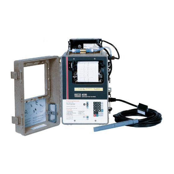
- Page 1 4220 Submerged Probe Flow Meter Installation and Operation Guide Part #60-3223-130 of Assembly #60-3224-052 Copyright © 2001. All rights reserved, Teledyne Isco, Inc. Revision T, March 6, 2006...
- Page 3 Teledyne Isco recommends that you read this manual completely before placing the equipment in service. Although Teledyne Isco designs reliability into all equipment, there is always the possi- bility of a malfunction. This manual may help in diagnosing and repairing the malfunc- tion.
- Page 5 4220 Flow Meter Safety 4220 Flow Meter Safety General Warnings Before installing, operating, or maintaining this equipment, it is imperative that all hazards and preventive measures are fully understood. While specific hazards may vary according to location and application, take heed in the following general...
- Page 6 4220 Flow Meter Safety DANGER DANGER – limited to the most extreme situations to identify an imminent hazard, which if not avoided, will result in death or serious injury. Hazard Symbols The equipment and this manual use symbols used to warn of hazards.
- Page 7 4220 Flow Meter Safety IMPORTANT – PLEASE READ WARNING The installation and use of this product may require you to work in locations where you could be seriously injured or even killed. Take whatever precautions are neces- sary to ensure your safety before entering the installation. Never work alone or unsu- pervised.
- Page 8 4220 Flow Meter Safety...
-
Page 9: Table Of Contents
4220 Flow Meter Table of Contents Section 1 Introduction 1.1 Description............1-1 1.2 Compatible Equipment . - Page 10 3.3.3 Mounting the 4220 ........
- Page 11 5.9.1 pH Probe Calibration ......... . 5-13 5.9.2 pH Probe Installation Guidelines .
- Page 12 1-2 4220 Controls and Indicators ........
- Page 13 1-1 Controls, Indicators, and Connectors ........1-7 1-2 Technical Specifications for the 4220 Flow Meter ......1-8 1-3 Technical Specifications for the 3222 Submerged Probe .
-
Page 15: Section 1 Introduction
Manual Organization This manual provides the information necessary to operate, maintain, and perform minor service on the 4220. The manual is organized into five sections: • Section 1: Introduction, operation, and specifications •... -
Page 16: Operating Principles
(weir or flume) or other open channel flow arrangement where a known relationship exists between level and flow rate. You can also use the 4220 to measure flow using the Manning equation. The level measuring device is a submerged probe. -
Page 17: Submerged Probe Operation
This transducer provides an output signal that changes proportionally to the pressure placed against it by the flow stream. The 4220 converts this signal to the flow rate with level-to-flow rate conversion formulas or tables characteristic of the primary device at the site. -
Page 18: Two Probes Available
1.3.3 Two Probes Available Teledyne Isco offers two different submerged probe level sensors for use with the 4220. The standard unit is intended for oper- ation in depths from 1 inch to 10 feet maximum. The other unit is capable of operation to depths as great as 30 feet. The difference in the probes is in the pressure transducer used inside. -
Page 19: Controls And Indicators
4220 Flow Meter Section 1 Introduction Figure 1-2 4220 Controls and Indicators... -
Page 20: Side View Showing Connectors And Pin Functions
Input Signal (+) E = Channel 3 (-) Black Temp (-) F = Channel 2 (+) Blue Temp (+) Switched 12V Input Signal (-) Submerged Ground Probe Level (+) Level (-) Ground Figure 1-3 4220 Side View Showing Connectors and Pin Functions... -
Page 21: Controls, Indicators, And Connectors
7-pin female M/S Connects flow meter to parameter sensor: temperature, pH, or D.O. Note that you can only have temperature and one parameter (pH or D.O.) at the same time. NOTE: The 270 D.O. module is no longer available from Teledyne Isco. -
Page 22: Technical Specifications
4220 Flow Meter Section 1 Introduction 1.6 Technical The technical specifications for the 4220 Flow Meter are found in Table 1-2. The anticipated longevity for a roll of paper used in the Specifications internal plotter is shown for various chart speeds in Table 1-4. -
Page 23: Technical Specifications For The 3222 Submerged Probe
4220 Flow Meter Section 1 Introduction Table 1-2 Technical Specifications for the 4220 Flow Meter (Continued) Flowlink Data Storage and Retrieval System Memory Partitions Maximum of 6 user-defined memory partitions for level or event stor- age. Data Storage Rate of data storage user-selected in 1, 2, 5, 10, 15, 30, 60, or 120 minute intervals. -
Page 24: How To Make Battery Calculations
4220 Flow Meter Section 1 Introduction Table 1-3 Technical Specifications for the 3222 Submerged Probe (Continued) Compensated Temperature Range 32° to 122°F (0° to 50° C). Temperature Error (over compen- 0.1 to 4.0 ft. (0.03 to 1.2 m) ±0.005 ft. per degree F sated temperature range) 4.0 to 10.0 ft. - Page 25 4220 Flow Meter Section 1 Introduction Battery capacity is expressed in ampere-hours. The battery manufacturer provides this information for each battery. This value is the product of a load current times an arbitrary time period, ten hours for nickel-cadmium batteries, and twenty hours for lead-acid types.
-
Page 26: Current Draw
Always operate these batteries with a reserve factor! 1.7.1 Current Draw Calculating current draw for a 4220 Flow Meter is somewhat more difficult than calculating the battery capacity. You cannot simply measure the idle current of the unit unless the printer and report generator are turned off in the program. -
Page 27: Measuring The Flow Meter Current
4220 Flow Meter Section 1 Introduction ® Fluke (or other current- averaging meter) FLUKE 87 TRUE RMS MULTIMETER 00 I 5 Flow Meter Connect Cable 60-1394-023, or you can make mA μA V Ω your own. lead – Battery, 12 Volt... - Page 28 4220 Flow Meter Section 1 Introduction 1-14...
-
Page 29: Section 2 Programming
4220 Flow Meter Section 2 Programming 2.1 Getting Started You must program the 4220 Flow Meter to accurately monitor a flow stream. You must also install the submerged probe level sensor. The 4220 will usually also need a primary measuring device, a structure placed across a stream that regulates flow. -
Page 30: Keypad Functions
4220 Flow Meter Section 2 Programming condition means that the flow meter will enable the sampler only when a certain condition or set of conditions, sensed by the flow meter, are met.) Total Flow Current Level Date (or pH/D.O.) Flow Rate Time (temperature) Following is a typical programming display on the flow meter. -
Page 31: Programming Procedure
4220 Flow Meter Section 2 Programming Print Program - Pressing this key will make the flow meter print out a complete list of the current program choices retained in memory. Print Report - One function of the flow meter is to print reports of all recorded activity at regular intervals. - Page 32 4220 Flow Meter Section 2 Programming If you want a different choice from the one that is flashing, you can move across the display by using the left and right arrow keys. Each time you press the right arrow key, the flashing selection will move one position to the right.
-
Page 33: Description Of Program Steps
4220 Flow Meter Section 2 Programming 2.3 Description of The Program Steps for the 4220 are: Program Steps 1. Operating Mode 2. Flow Conversion 3. Adjust Level/Parameters 4. Reset Totalizer 5. Sampler Pacing 6. Sampler Enable 7. Alarm Dialout 8. Printer 9. - Page 34 Step 2, Flow Conversion Type, determines how the flow meter Conversion Type calculates flow rate and total flow. For the 4220 Flow Meter, flow rate is calculated by knowing the measured level and (usually) the characteristics of a structure called a primary measuring device.
- Page 35 19th-century Irish civil engineer. There is no primary measuring device as such. Instead the pipe, with considerations for its slope and internal roughness, serves as the primary device. The 4220 Flow Meter can calculate flow in round pipes, rectangular, U-shaped, or trapezoidal channels based on this formula.
-
Page 36: The Ysi 600 Sonde
It is intended for use in research, assessment, and regulatory compliance. The sonde attaches to the modified RAIN GAUGE connector on the 4220. Flow meters having only a 4-pin rain gauge connector will not support the YSI Sonde. If you wish to upgrade your flow meter to use this system, contact the factory. - Page 37 4220 Flow Meter Section 2 Programming control. There are several possible options—DISABLE, CONDI- TIONAL, VOLUME, and FLOWLINK. DISABLE will keep the sampler from receiving a flow pulse from the flow meter. VOLUME allows the flow meter to signal the sampler whenever a specific flow volume has passed by.
- Page 38 2.3.8 Step 8 - Printer All 4220 Flow Meters have a built-in printer. The printer is more than just a printer, as it is capable of plotting linear data along with printing alphanumeric (letters and numbers) messages. In "...
- Page 39 50 history items and 200 sample events at a time. 2.4 Interpreting the Following are the program screens as they appear on the display of a 4220 Flow Meter. Explanations of most of the screens will be Program Screens provided.
- Page 40 DO/PH READING INTERVAL refers to the measurement of spe- cific aspects of the flow stream other than amount. 4220 Flow Meters support measurement of three different characteristics: temperature, pH (the relative acidity or alkalinity of a solution), and D.O., dissolved oxygen.
- Page 41 After selecting the appropriate parameter reading interval, press Enter. The Setup menu will reappear. This time select STATUS from the Setup menu. Press Enter. The following will appear: MODEL 4220 HW REV: XXXXXX SW REV X.XX ID XXXXXXXXXXX HW REV refers to the hardware revision number.
- Page 42 4220 Flow Meter Section 2 Programming Return to the Setup menu if the unit has not already done so. This time select ENABLE/ALARM HYSTERESIS from the menu. Press Enter. The following will appear: LEVEL ENABLE/ALARM HYSTERESIS X.XXX FT (or other units of measure)
- Page 43 10-50 mA (not supported by the flow meter). Teledyne Isco offers two different arrangements for the 4-20 mA control circuit. You can have either or both with the same flow meter.
- Page 44 16 mA, whether activated or not. While 4-20 mA applications are generally made in installations with com- mercial power available, Teledyne Isco suggests the following for those who have a 4-20 mA output in a battery-powered installation.
- Page 45 4220 Flow Meter Section 2 Programming occurs, return to the 4 - 2 - 0 option, and at the prompt enter 0 for the number of outputs activated. This will restore the exter- nal 4-20 mA converter capability. MANUAL CONTROL will appear if you continue moving to the right.
-
Page 46: Ascii Output Codes
The information in the following section is provided for those who can write their own software programs to process the data transmitted from the Serial Output port. Special cables may be required. Contact Teledyne Isco technical support for more information. Serial Output – Returning to the OPTIONAL OUTPUTS menu, you will see the SERIAL OUTPUt option. - Page 47 4220 Flow Meter Section 2 Programming Table 2-1 ASCII Output Codes (Continued) Code Parameter Units YCO YSI 600 Conductivity Millisiemens per centimeter YSI 600 Specific Conductance Millisiemens per centimeter YSI 600 Salinity Parts per thousand YSI 600 Total Dissolved Solids Milligrams per liter...
- Page 48 4220 Flow Meter Section 2 Programming Note It is important to use CHECKSUM if you plan to use internal modems or the interrogator. The UART is shared with these devices. If you select SERIAL OUTPUT from the OPTIONAL OUTPUTS menu, the following display will appear: PERIODIC SERIAL OUTPUT •...
- Page 49 4220 Flow Meter Section 2 Programming If you select any of these outputs, the flow meter will request that you turn them on or off. If you are running on battery and do not intend to use either of these options, select OFF. Otherwise, select ON.
- Page 50 4220 Flow Meter Section 2 Programming Select YES if you want DO/PH to appear in the report. Note that you must have the appropriate sensor connected to the flow meter to sense parameters; the flow meter is capable of sensing temperature, pH and temperature, and D.O.
- Page 51 4220 Flow Meter Section 2 Programming Press Exit to leave the program. Then press Enter and reselect SETUP. The Setup menu will reappear: SETUP OPTIONS: 'EXIT' TO QUIT • STATUS • • REPORT SETUP • • LCD BACKLIGHT • SET CLOCK, SITE ID, MEASUREMENT SETUP, PROGRAM LOCK, PROGRAM are off-screen and can be reached with the arrow keys.
- Page 52 Further changes will require entry of the password, which is the model number of the flow meter: 4220. If you select ON, there is a time-out before the lock engages. If you continue to work through the rest of the program, the lock will not engage until you are done.
- Page 53 4220 Flow Meter Section 2 Programming temperature. Press Enter. The following will appear. You will have to press the right arrow key several times to see all of the options displayed in the following menu: FLOW RATE UNITS OF MEASURE •...
- Page 54 You must have an Isco Dissolved Oxygen Probe (or approved equivalent) to sense dissolved oxygen. The probe attaches to an amplifier box, which attaches to the Parameter Port. Note The 270 D.O. module is no longer available from Teledyne Isco. 2-26...
- Page 55 YSI 600 Multi-Parameter Sonde. This probe allows you to measure several different characteristics of a flow stream at the same time. The YSI 600 Sonde attaches to the Rain Gauge con- nector on the 4220. This connector must be a special, modified connector with nine pins. Note 4220 Flow Meters with 4-pin Rain Gauge connectors cannot support the YSI 600.
- Page 56 4220 Flow Meter Section 2 Programming NO is the default. If you select YES, the following display will appear: WARNING – DO NOT DISCONNECT POWER YSI COMMUNICATION CHECK. PLEASE WAIT... CAUTION Do not disconnect either sonde or flow meter power during a communications check.
-
Page 57: Step 2, Flow Conversion Type
4220 Flow Meter Section 2 Programming This value is provided because conductivity rises (~2%/ °C) with temperature. The default setting is 1.91%. This value is the tem- perature coefficient for pure KCl (potassium chloride) in water. For other salts this value will be somewhat inaccurate, but it... - Page 58 4220 Flow Meter Section 2 Programming If you select V-NOTCH, the following will appear: SELECT V-NOTCH WEIR ANGLE (IN DEGREES) • 22.5 • • 30 • • 45 • • 60 • • 90 • • 120 • If you select RECTANGULAR, the following will appear: END CONTRACTIONS ON RECTANGULAR WEIR: •...
- Page 59 4220 Flow Meter Section 2 Programming If you select LEOPOLD-LAGCO, this will appear: LEOPOLD-LAGCO FLUME SIZE • 4" • • 6" • • 8" • • 10" • • 12" • • 15" • • 18" • • 21" •...
- Page 60 4220 Flow Meter Section 2 Programming If you select ROUND PIPE for the Manning flow conversion, the following displays will appear: MANNING ROUND PIPE SLOPE = X.XXXXX ROUGH = X.XXXX Slope is entered as a dimensionless quantity, delta Y/ delta X, not as percent slope.
- Page 61 DATA POINT flow conversion allows you to enter measured level and flow rate values for a number of different points. The 4220 Flow Meter can accept up to four sets of data points with each set containing as many as fifty points.
- Page 62 4220 Flow Meter Section 2 Programming The level- to-flow rate data for such devices is usually available from the manufacturer. From this data the flow meter can create a flow conversion based on the relationship between the level and flow rate. After the FLOW RATE UNITS menu has appeared, the...
- Page 63 4220 Flow Meter Section 2 Programming The flow meter's internal resolution and its accuracy are based on the value you enter for Maximum Head. The flow meter will display: FLOW RATE AT MAXIMUM HEAD X.XXX CFS (or other units of measure)
-
Page 64: Measuring Level In Round Pipes
4220 Flow Meter Section 2 Programming current range is selected). The flow meter will then request that you repeat the process of defining the data type and setting the minimum and maximum values for any of the other analog ports you activated previously in Setup. - Page 65 4220 Flow Meter Section 2 Programming over 14%! Errors in level measurement have a greater effect on flow cal- culations at low liquid levels. Dimensional errors tend to be more significant at higher levels. If you select pH for Parameter to Adjust, the following display will appear.
- Page 66 4220 Flow Meter Section 2 Programming Absolute barometric pressure is barometric pressure not corrected to sea level. The barometric pressure published by the U.S. Weather Bureau is adjusted to sea level. If you use their value, you must convert it to the absolute pressure for your altitude.
- Page 67 4220 Flow Meter Section 2 Programming If you select pH for the parameter to calibrate, the following display will appear: YSI 600 pH CALIBRATION • pH 4 & 7 • • pH 7 & 10 • • pH 4, 7, & 10 •...
- Page 68 4220 Flow Meter Section 2 Programming Then: PLACE PROBE IN X.XX PPT PRESS ENTER WHEN STABLE: X.XX MS/CM Then: CALIBRATING... PLEASE WAIT... There is no need to calibrate the YSI 600 temperature sensor, as it is self-calibrating. 2-40...
-
Page 69: Ysi 600 Sonde Calibration Flow Chart
4220 Flow Meter Section 2 Programming Figure 2-3 YSI 600 Sonde Calibration Flow Chart 2-41... -
Page 70: Step 4 - Reset Totalizer
4220 Flow Meter Section 2 Programming 2.4.6 Step 4 - Reset Totalizer This step allows you to reset the flow meter's internal flow totalizer. Note that there is the possibility of more than one totalizer. All models have the capability of maintaining a sep- arate totalizer for the time the sampler is enabled through the sampler enabling feature (step 6). - Page 71 4220 Flow Meter Section 2 Programming trols the flow meter remotely, via phone lines and a modem, or locally with a laptop computer and cable. In any event, if the sampler pacing definition is controlled by Flowlink, it can only be changed through Flowlink.
-
Page 72: Step 6 - Sampler Enable
4220 Flow Meter Section 2 Programming After you have determined what condition will signal the sampler and under what circumstances, the following menu will appear: SELECT OPERATOR • DONE • • OR • • AND • SELECT OPERATOR allows you to trigger the sampler from a single condition or from two conditions. - Page 73 4220 Flow Meter Section 2 Programming useful where the sampler needs to remain idle for long periods of time, such as storm water runoff applications. When you select or advance to step 6, the following display will appear: SAMPLER ENABLE MODE •...
- Page 74 4220 Flow Meter Section 2 Programming chosen from this menu before the flow meter recognizes the event as a storm. The next menu defines the interval that must pass between storm events. TIME SINCE LAST RAINFALL DAYS: X (allowable entry of 1-7)
-
Page 75: Step 7 - Alarm Dialout Mode
4220 Flow Meter Section 2 Programming determine whether both conditions are necessary for enabling (AND) or whether either condition will enable the sampler (OR). If you select FLOW RATE: FLOW RATE • GREATER THAN • • LESS THAN • • RATE OF CHANGE •... - Page 76 4220 Flow Meter Section 2 Programming Note You must have the optional internal modem installed and con- nected to a telephone network to make use of this feature. This menu will not even appear if you do not have a modem. The flow meter will automatically advance to the next step.
- Page 77 4220 Flow Meter Section 2 Programming least one of the options will be available to you. As mentioned for other program steps, some of these menu options may not appear depending on the flow meter you have and choices you made earlier in the program.
-
Page 78: Step 8 - Printer
4220 Flow Meter Section 2 Programming arranged in decreasing priority. NUM 1 carries the highest pri- ority, followed by NUM 2 and so on. After you have entered the numbers, the flow meter will request: DELAY BETWEEN DIALOUTS XX MINUTES This is the time delay between calling the first number and calling the second, etc. - Page 79 4220 Flow Meter Section 2 Programming (TEMPERATURE), (YSI pH), (YSI D.O.), (YSI CONDUC- TIVITY), and (YSI TEMP) can also appear. Remember that menus in parentheses may not appear due to previous program selections. Either pH or D. O. may appear, but not both. The various YSI options will only appear if you enabled the YSI 600 in step 1.
-
Page 80: Step 9 - Reports/History
4220 Flow Meter Section 2 Programming (TEMPERATURE), (YSI pH), (YSI D.O.), (YSI SALINITY), and (YSI TEMP) may also appear. Again, as for line A, you can select another condition to plot on the chart. The flow meter will request a full-scale value. The full-scale value can be different from that of line A. - Page 81 4220 Flow Meter Section 2 Programming The second report generator lets you program the flow meter to print two independent reports at different intervals, for example. This is useful for those who need both a weekly and a monthly summary of activity on the flow meter. If you select OFF for this step, the program will advance to the next step, and there will be no report B generated.
- Page 82 4220 Flow Meter Section 2 Programming Flow Meter History Contents: D. O. ADJUSTED pH ADJUSTED LEVEL ADJUSTED FLOW CONVERSION CHANGED PLOTTER SPEED CHANGED PLOTTER TURNED ON PLOTTER TURNED OFF TIME CHANGE FROM TIME CHANGE TO REPORT A CHANGED REPORT B CHANGED...
-
Page 83: Section 3 Installation
Section 3 Installation 3.1 Introduction This section of the manual contains detailed information on the installation of the 4220 Flow Meter. Included are sections on the power sources, mounting methods, interconnection wiring, installation of the submerged probe and setup procedure for the unit. - Page 84 However, if the blockage is inside the submerged probe's cable, the probe will have to be returned to the factory for evaluation. In some cases, Teledyne Isco’s service department can vacuum moisture from the reference line. However, if the blockage cannot be vacuumed out, or if moisture remains inside the probe for a prolonged period, the probe will be ruined beyond repair.
-
Page 85: Opening The Case
3.2.2 Isco Sampler If you combine a 4220 Flow Meter with an Isco Wastewater Sampler in a flow-proportional sampling system, you can power the flow meter from the sampler's power supply. Connect the flow meter to the sampler with the Isco flow meter-to-sampler cable. -
Page 86: Isco Nickel-Cadmium Battery
3.2.3 Isco Nickel-Cadmium Teledyne Isco offers a 4 ampere-hour 12-volt rechargeable Battery nickel-cadmium battery pack to power the flow meter. Teledyne Isco packages this battery specifically for use with Isco flow meters and samplers. Refer to the Power Products Guide accom- panying this manual for detailed information about this battery and the procedure for charging it. -
Page 87: Isco Lead-Acid Battery
“sparking” the output (shorting the terminals together with a screwdriver or other tool). 3.2.7 AC Power Supplies Teledyne Isco also offers two different AC power supplies, the High Capacity Power Pack and the Battery-Backed Power Pack to power the flow meter. These power packs are designed for operation from 120 Volts AC, 50/60 Hz commercial power sources. -
Page 88: Attaching The Power Supply
4220 Flow Meter Section 3 Installation Figure 3-2 Power Pack Installed on a Flow Meter They are both capable of powering the flow meter. The Battery-Backed Power Pack provides 12 VDC at 5 Amperes, and is backed up by a 1.2 Ampere- hour nickel-cadmium battery. This... -
Page 89: Flow Meter Mounting And Installation Procedures
Charge the battery in accor- dance with the manufacturer's instructions. Figure 3-3 4220 Flow Meter Suspended by the Handle (handles may vary) 3.3 Flow Meter Mounting Because the 4220 Flow Meter is a portable device, you may or may not install it permanently. -
Page 90: Location Of The Flow Meter
Box can be found in Section 5 of this section. 3.3.3 Mounting the 4220 The 4220 does not have any special requirements for mounting. You can locate it on any relatively flat surface either horizontally, supported by the two mounting pads and the stainless steel mounting bracket, or vertically, supported by the two plastic rails on the bottom of the case. -
Page 91: Quick-Disconnect Box For The Submerged Probe (Cover Removed)
To use the Quick-Disconnect box, you will need a cable of the correct length with an M/S connector to plug into the flow meter. Teledyne Isco will build the cable with the proper connector on one end and stripped wire ends on the other as a special order. -
Page 92: Extension Cables
3.5 Extension Cables The standard (10 foot depth) probe for the 4220 has a 25-foot cable. The 30 foot depth probe has a 50-foot cable. If these lengths are insufficient, Teledyne Isco offers extension cables for use with the probes. -
Page 93: Isco Sampler Interface
3.7 Isco Sampler Interface One of the uses of the 4220 Flow Meter is to control a sampler in a flow-paced sampling mode. Flow-paced sampling means that the flow meter is programmed to signal the sampler to take a sample after a specific volume of flow has passed through the flow stream, rather than after a particular period of time. - Page 94 4220 Flow Meter Section 3 Installation 3-12...
-
Page 95: Section 4 Submerged Probe Installation
For pipes larger than 15 inches in diameter, Teledyne Isco offers the Universal Mounting Ring. For use in similarly-sized manhole inverts, you can use the base and extension sections of the Universal Mounting Ring without the scissors section. -
Page 96: Functionality Under Solids
4.2 Submerged Probe Teledyne Isco provides three nose sections, each designed for spe- cific flow stream conditions. Nose Sections A complete list of nose sections and their part numbers can be Standard Nose found in Appendix B. -
Page 97: Mounting Rings
These mounting rings are available for use in pipes with inside diameters of 6" (15.2 cm), 8" (20.3 cm), 10" (25.4 cm), 12" (30.5 cm), and 15" (38.1 cm). The Teledyne Isco part numbers for the various size mounting rings available are listed in Appendix B. -
Page 98: Sensor Installed On A Spring Ring
4220 Flow Meter Section 4 Submerged Probe Installation Compress ring into gap to install in pipe, then..outward force of ring against pipe wall holds ring in place inside pipe. Figure 4-1 Sensor Installed on a Spring Ring Attaching the Sensor to the Attach the probe to the ring either by using two 4-40 x "... -
Page 99: Spring Ring Preparation
4220 Flow Meter Section 4 Submerged Probe Installation Figure 4-2 Spring Ring Preparation Figure 4-3 Mounting Ring in a Round Pipe CAUTION Make sure the sensor cable is securely fastened along the back (downstream) edge of the ring. Otherwise, the sensor may provide inaccurate level readings under conditions of high velocity. -
Page 100: Universal Mounting Rings
4.3.2 Universal Mounting For pipes larger than 15" in diameter, Teledyne Isco offers the Rings adjustable Universal Mounting Ring (also known as the “Scissors Ring”). - Page 101 4220 Flow Meter Section 4 Submerged Probe Installation Assembling the Rings The scissors mechanism will work best if the respective assembly is installed to allow the scissors to expand approximately in the middle of the adjustment. Do not overtighten the mech- anism.
-
Page 102: Universal Mounting Ring Parts
4220 Flow Meter Section 4 Submerged Probe Installation 9" 21.5" Extension #1 68-3000-038 31.5" (pair) 60-3004-172 (each) 41.5" 43.7 " Extension #2 68-3000-039 (pair) 60-3004-173 (each) Extension #3 3.4" min 68-3000-040 15.9 max (pair) 60-3004-174 (each) Scissors Mechanism Standard Base Section... -
Page 103: U-Channel Or Invert Mounting
4220 Flow Meter Section 4 Submerged Probe Installation To prevent debris from catching on the cable, it is important to attach the cable to the mounting ring so it offers as little resis- tance to the flow as possible. Attach the sensor cable to the down- stream edge of the ring, using the self-locking plastic ties supplied with the ring. -
Page 104: Completing The Probe Installation
4.4.3 Weirs and Flumes The 4220 Flow Meter is generally used with some type of primary measuring device, such as a weir or flume. The placement of the submerged probe in the primary device is deter- mined by the type of primary device. -
Page 105: Locating The Head-Measuring Point
4220 Flow Meter Section 4 Submerged Probe Installation the mounting ring are not suitable, you must build your own mounting hardware. Figure 4-6 shows the dimensions of the probe for your reference when building your own hardware. Figure 4-7 shows the probe installed in several primary devices. -
Page 106: Submerged Probe Dimensions
4220 Flow Meter Section 4 Submerged Probe Installation that certain flume manufacturers produce flumes with built-in cavities designed specifically for use with Isco submerged probe level sensors. Typically, these are Parshall or Palmer-Bowlus flumes. Contact the manufacturer for details on these flumes. -
Page 107: Typical Primary Device Installations
1. Handle Flume 2. Ring Base Bottom Assembly Parshall Flume Round Pipe Probe Mounted Contact the factory or your Teledyne Isco in Recess Representative for additional information about the Street Level Installation system. Figure 4-7 Typical Primary Device Installations 4-13... -
Page 108: Securing Probe With A Weighted Plate
4220 Flow Meter Section 4 Submerged Probe Installation 4.4.4 Securing Probe with a In situations with a minimal flow velocity (for example, in a Weighted Plate stilling well), you can simply attach the probe to a weighted plate and submerge it in the flow. -
Page 109: Section 5 Options And Accessories
4200 Series Flow Meter. Application-specific options are covered in the Instal- lation sections of each type of flow meter. Teledyne Isco offers the following options for use with all 4200 series flow meters: • 4200T Modems •... -
Page 110: Modems And Flowlink Software
4220 Flow Meter Section 5 Options and Accessories mode. It operates at 300/1200/2400 baud. This modem has speech and tone capabilities and comes with a connect cable to attach to the telephone line. Note The modem is disabled when an interrogator cable is con- nected to the flow meter’s interrogator port. -
Page 111: Types Of Service
“If trouble is experienced with this equipment, please contact the Teledyne Isco Customer Service Department, (800) 228-4373 or, outside the U.S.A., call (402) 464-0231, for repair and (or) warranty information. If the trouble is... -
Page 112: Connection To External Serial Device
This option (SERIAL OUTPUT) is discussed in detail in Section 2. Teledyne Isco offers a 300 baud output on the RAIN GAUGE con- nector. This port provides ASCII level and flow rate data for remote transmission to any ASCII-compatible equipment. Every... -
Page 113: External Analog Output Interface
4 mA becomes the 0% or baseline for the condition, while 20 mA becomes the 100% or full-scale of the condition. Teledyne Isco offers two different arrangements for providing the 4-20 mA outputs. -
Page 114: Internal Multiple Analog Output Board
Maximum Distance 1,500 ft. (457.3 m) using 18 AWG wire. 5.3.2 Internal Multiple For those needing more than one analog output, Teledyne Isco Analog Output Board offers the Multiple Analog Output Board, which is installed inside the flow meter. This board provides from one to three iso- lated analog outputs. -
Page 115: Tipping Bucket Rain Gauge
You may disregard these wires, as they are not connected in this application. 5.4 Tipping Bucket Rain A Tipping Bucket Rain Gauge is available from Teledyne Isco for use with 4200 Series Flow Meters. The gauge connects to the Gauge flow meter by a cable terminated in an M/S connector. -
Page 116: Isco Flowlink Software
Flowlink Software is available from its manual or from the factory. 5.6 High-Low Alarm Relay Teledyne Isco offers a control box that monitors flow rate data available from any 4200 Series Flow Meter. Alarm relays trip when the flow rate exceeds or falls below pre-selected limits. -
Page 117: Installation
Flow Meter Meter requires a cable and an M/S connector. A special cable, 25 feet long, is available from Teledyne Isco. On one end of the cable is a 4-pin, male M/S connector. Plug this connector into the Remote Printer/Rain Gauge connector on the flow meter. The... -
Page 118: Parameter Sensing With Isco 4200 Series Flow Meters
REEN DATA HITE 5.7 Parameter Sensing The Isco 4220 Flow Meter has the capability of displaying, with Isco 4200 Series recording and (if Flowlink software is used) storing data provided from parameter sensors. The parameter sensors available for the Flow Meters... -
Page 119: The Temperature Probe
4220 Flow Meter Section 5 Options and Accessories The Parameter Modules themselves plug into the Parameter Probe connector on the flow meter. CAUTION The pH and D.O. probes require continuous submersion after installation, or they will lose sensitivity. Prolonged dehydra- tion of the sensor bulb may damage or even ruin the pH probe. -
Page 120: Ph Probe (With Protective Cap)
4220 Flow Meter Section 5 Options and Accessories The dissociation constant is a number indicating the degree of ionic dissociation for a substance after it is dissolved in water. Dissociation constants vary widely for substances depending on the nature of the substance’s chemical bonds. Ionic salts tend to have higher constants. -
Page 121: Ph Probe Calibration
The flow meter determines the pH value and displays 5.9.1 pH Probe Calibration The 4220 provides a two- or three-point calibration for the pH probes with commercially-prepared calibrated buffer solutions. Calibrations of 4 and 7, 7 and 10, and 4, 7, and 10 are all pos- sible. -
Page 122: Ph Probe Installation Guidelines
4220 Flow Meter Section 5 Options and Accessories 3. Now go to step 3. PARAMETER TO ADJUST - NONE, LEVEL, pH. (Other selections may appear.) Select pH. If the pH menu does not appear in step 3, go back to step 1 to make sure you have turned it on. - Page 123 4220 Flow Meter Section 5 Options and Accessories Greasy substances, being nonconductors of electricity, weaken the electrical potentials formed between the glass mono-electrode and the solution, slowing or halting the response altogether. The pH Sensor operates satisfactorily mounted either horizon- tally or vertically in the stream.
-
Page 124: Ph Parameter Module
4220 Flow Meter Section 5 Options and Accessories Figure 5-4 pH Parameter Module Note When installing the pH probe and its sensor carrier, make sure the mounting slots on the carrier are completely pressed into the mating tabs on the ring. The probe relies on a full engage- ment between tabs and slots for secure mounting. -
Page 125: Storage And Maintenance Of Ph Probes
4220 Flow Meter Section 5 Options and Accessories The Isco amplifier box extends the allowable distance between the probe and the flow meter. The probe has a 25-foot cable, so you must mount the amplifier within this distance. The maximum distance between the amplifier box and the flow meter is 1,000 feet. -
Page 126: The Dissolved Oxygen (D.o.) Probe
4220 Flow Meter Section 5 Options and Accessories tap water could revive the electrode in more severe situations. If none of these solutions work, it may be necessary to replace the probe. 5.10 The Dissolved Oxygen (D.O.) Probe Note The 270 D.O. module has been discontinued. Probes, service kits, and accessories are still available to maintain existing field units. -
Page 127: How The D.o. Probe Works
4220 Flow Meter Section 5 Options and Accessories Tests conducted by Isco with probes installed in various waste streams have indicated that greases and solids quickly coat the probe's membrane, making it impos- sible for oxygen to enter the reaction chamber. This will result in an abnormally low reading, or no reading at all. -
Page 128: Membrane Thicknesses
4220 Flow Meter Section 5 Options and Accessories 4. Place the O-ring on top of the membrane, generally con- forming to the circumference edge of the probe. 5. Place the thumb and index finger from both hands opposite each other on the O-ring at equal distances. - Page 129 4220 Flow Meter Section 5 Options and Accessories use. Contents of the flow stream are also important, as some substances will foul the membrane very quickly. Erratic readings will result from loose, wrinkled or fouled membranes, or from large bubbles in the electrolyte reservoir.
-
Page 130: Calibrating The D.o. Probe With A Flow Meter
4220 Flow Meter Section 5 Options and Accessories probe. Use only 2-mil membranes with D.O. probes connected to Isco flow meters. Table 5-4 D.O. Probe Specifications Cathode Gold Anode Silver Membrane FEP Teflon; 2 mil standard Electrolyte Half-saturated KCl (Potassium Chloride) Temp. -
Page 131: Installation Of Parameter Probes In Mounting Rings
4220 Flow Meter Section 5 Options and Accessories Note You must use the Isco Temperature Probe with the D.O. Probe to provide temperature compensation. Wrap both the D.O. Probe and Temperature Probe in a damp cloth. Wait ten minutes for it to stabilize, then proceed. -
Page 132: The Ysi 600 Multiple Parameter Sonde
4220 Flow Meter Section 5 Options and Accessories Scissors Rings. You can also install them in other ways with custom hardware as is appropriate for your situation. For details on the Spring Rings and the Scissors Ring, refer to Section 4. -
Page 133: Ysi 600 Probe Specifications
4220 Flow Meter Section 5 Options and Accessories the flow meter. You can use the YSI 600 as deep as 200 feet below the surface, or in as little as a few inches of water. The fast sensor response of the YSI 600 makes it ideal for vertical profiling. Its small size means it can fit inside two-inch diameter monitoring wells. -
Page 134: Mechanical Totalizer
Resolution 0.1 ppt 5.13 Mechanical Totalizer A mechanical totalizer is available for the 4220 that consists of a seven-digit, non-resettable mechanical counter mounted in the front panel. It must be ordered with the flow meter. The totalizer advances according to program selections for units of measure and the maximum flow of the primary device used. -
Page 135: Section 6 Maintenance And Service
CMOS circuitry. Teledyne Isco recommends that you become familiar with the maintenance procedures presented here. While the 4220 is rug- gedly built to withstand severe field conditions, it will function best and remain most reliable if you follow these simple proce- dures. -
Page 136: Reactivation Of The Desiccators
4220 Flow Meter Section 6 Maintenance and Service 6.2 Reactivation of the The 4220 has a reusable desiccant canister held by a steel clamp on the inside of the case lid. There is also a tubular desiccant car- Desiccators tridge on the top of the case next to the connectors. The canister contains silica gel that adsorbs moisture trapped inside the flow meter's case when it is closed. -
Page 137: Regenerating The External Desiccant Cartridge
4220 Flow Meter Section 6 Maintenance and Service 6.2.2 Regenerating the Teledyne Isco uses two types of silica gel: External Desiccant • One looks like small beads or pellets that are blue-black Cartridge when dry, pale pink to transparent when saturated. -
Page 138: Care Of The Submerged Probe And Cables
4220 Flow Meter Section 6 Maintenance and Service Note Regeneration of the desiccators is extremely important. Saturated desiccators let the flow meter draw moisture inside, exposing both mechanical and electronic components to water and/or chemical contamination. The air in many installations contains fumes that will form acids in the presence of moisture. -
Page 139: Cleaning The Submerged Probe Without Disassembly
4220 Flow Meter Section 6 Maintenance and Service 6.3.2 Cleaning the Occasionally, organic materials may become jammed inside the Submerged Probe submerged probe's housing. If this material swells as it becomes Without Disassembly saturated with water, it will exert pressure on the stainless dia- phragm placed over the transducer. -
Page 140: Cable Inspection
4220 Flow Meter Section 6 Maintenance and Service Again, any deformation of the stainless steel diaphragm will per- manently disable the submerged probe. If you must remove the nose of the probe, do it very carefully. A small warning disk is located in front of the transducer. -
Page 141: Maintenance Of The Printer
4220 Flow Meter Section 6 Maintenance and Service 6.4 Maintenance of the The internal printer needs little maintenance beyond changing the chart roll and the ink ribbon. Printer Refer to the pictures provided for each section. Also refer to the label inside the cabinet. - Page 142 4220 Flow Meter Section 6 Maintenance and Service 6. Remove the feed spool by pulling on the handle extending from the right side of the printer. 7. Snap off the other white end cap as described previously. Save the white end caps; you will reuse them.
-
Page 143: Ink Ribbon Replacement
4220 Flow Meter Section 6 Maintenance and Service Figure 6-5 Changing the Ink Ribbon 6.4.2 Ink Ribbon Ribbon life will vary greatly from one installation to another Replacement depending on how often the printer has to print. When the char- acters on the chart become difficult to read, you should replace the ribbon. -
Page 144: Do Not Disassemble Or Lubricate The Printer
Teledyne Isco recommends you make no attempt to oil or disas- semble the mechanism if it malfunctions. -
Page 145: Fuse Replacement
4220 Flow Meter Section 6 Maintenance and Service Note If you disassemble the flow meter for servicing, you will also remove the aluminum chassis covers to access the circuitry. Always replace these covers when repairs have been com- pleted. The covers protect the circuit boards and also reduce signal emissions that could interfere with the operation of nearby electronic equipment. -
Page 146: Display Warnings
CAUTION This procedure will cause most programmed entries and accu- mulated data stored in the 4220 to be lost, and the flow meter will revert to factory default settings. If this operation is per- formed, it will be necessary for you to reprogram the unit to meet the specifications of your installation. -
Page 147: Preliminary Troubleshooting Steps
If these messages appear, call the Teledyne Isco Customer Service Department at (800) 228-4373. CAUTION Do not attempt to disassemble or repair the 4220 Flow Meter (other than changing fuses) unless you are skilled in the evalu- ation and repair of microprocessor-based circuitry. Teledyne Isco recommends no attempt be made to disassemble or repair the printer mechanism or display module. -
Page 148: Inspection Protocol
Following are suggested areas to check before attempting to service the 4220’s circuitry. Telephone consultation with Cus- tomer Service is strongly recommended. Look for the following: 1. Verify that the problem is in the flow meter and not caused... -
Page 149: Precautions For Servicing Cmos Circuitry
11. Check the reset circuitry to see that it is working properly. 6.7 Precautions for Most of the circuitry in the 4220 Flow Meter is made up of CMOS Servicing CMOS components. Because of the oxide gate structure of these devices,... -
Page 150: Using Flash Update
6.8 Using FLASH UPDATE Teledyne Isco manufactures a number of instruments - 4100 Series Flow Loggers, 4200 Series Flow Meters, and 6700 Series Samplers - that use circuitry based on FLASH EPROMs. Unlike... -
Page 151: Before Running Flash Update
Then, after updating the software, reprogram the instrument. • If you have Flowlink, Teledyne Isco strongly recommends using it to update 4200 Series Flow Meters. Flowlink lets you collect the data stored in the instrument before updating the software. -
Page 152: Running Flash Update
The numbers following the “V” are the software version. If several versions appear in the window, select the version with the highest number unless otherwise instructed by Teledyne Isco Technical Service. Figure 6-8 Update File Menu 6-18... -
Page 153: Options Menu
4220 Flow Meter Section 6 Maintenance and Service Options Menu Figure 6-9 Options Menu Select the COM port that corresponds to the serial port used for the Computer Connect Cable. Select Newest Version to see only the most recent update files in a directory. -
Page 154: Minimum Dos And Computer Hardware Requirements
4220 Flow Meter Section 6 Maintenance and Service Table 6-1 Minimum DOS and Computer Hardware Requirements DOS 3.3 or later versions DOS 5.0 or later versions recommended. Microsoft Windows not required. 80286, 80386, 80486 IBM PC or compatible. 80386 or 80486 recommended. -
Page 155: Appendix A Replacement Parts
4220 Flow Meter Appendix A Replacement Parts The following illustrations show replacement parts for the 4220 Flow Meter. Find their corresponding line numbers in Table A-1 for part numbers and descriptions. Replacement parts can be purchased by contacting Teledyne Isco’s Customer Service Department. - Page 156 4220 Flow Meter Appendix A Replacement Parts...
- Page 157 4220 Flow Meter Appendix A Replacement Parts...
-
Page 158: Replacement Parts List
Motor Assy Chart Drive 4200 60-3214-093 LCD Module Assy B/L 60-3224-070 Case Bottom Sub Assembly 60-3214-098 PCB Assembly Keyboard 60-3224 -071 PCB Assy 4220 CPU w/Software 60-3224-056 PCB Assembly 4220 Amplifier 60-3214-120 Wiring Assy - 12 VDC/Sampler 60-3214-122 Wiring Assy - Interrogator 60-3214-140... - Page 159 4220 Flow Meter Appendix A Replacement Parts Table A-1 Replacement Parts List (Continued) Part Number Complete Part Description O-Ring Silicone #120 .99 ID × .1 W 202-4001-20 60-3214-141 Case Latch Assy 109-0605-03 Draw Latch Assy - Small 109-0609-00 Cabinet Catch White ⁄...
- Page 160 4220 Flow Meter Appendix A Replacement Parts...
-
Page 161: Appendix B Accessories List
Caution Tag ..........................60-3003-256 Dri-Can Desiccant ........................099-0012-00 Flow Data Handbook........................ 60-3003-041 4220 Accessories 4220 Flow Meter Instruction Manual ..................60-3224-052 4220 Flow Meter Pocket Guide....................60-3223-103 Standard Nose Section ......................60-2503-086 Slanted Nose Section........................ 60-2503-097 Flume Probe Cap ........................60-2503-105 Submerged Probe, 10’... - Page 162 4220 Flow Meter Appendix B Accessories List Optional Equipment High-Low Alarm Relay Box ..................... 60-3404-028 4-20 mA Output Interface......................60-1784-039 674 Rain Gauge (0.01”) ......................60-3284-001 674 Rain Gauge (0.1mm)) ......................60-3284-006 Chart Roller ..........................60-3004-156 Spreader Bar..........................60-3004-110 pH Probe and 201 pH Module (25 ft. cable standard) ............68-4200-002 (Includes probe, built-in temperature sensor) D.O.
- Page 163 4220 Flow Meter Appendix B Accessories List Miscellaneous – for use with the YSI Sonde Calibration/Transport Bottle Kit..................... 60-0603-216 Carrying Case for YSI 600, cables, accessories, tools ............. 60-0603-217 YSI 600 Instruction Manual ....................60-0603-218 YSI 600 to Isco 4200/6700 Adapter Cable ................60-0604-001 YSI 600 and Isco 674 Rain Gauge Y-Connect Cable...............
- Page 164 4220 Flow Meter Appendix B Accessories List...
-
Page 165: Appendix C Programming Worksheets
Appendix C Programming Worksheets Use this form to make a hard copy of the program you use in your 4220. Most program steps can be completed in the shop without the flow meter being installed or at the job site. However, please note the following: •... - Page 166 4220 Flow Meter Appendix C Programming Worksheets 7. YSI 600 Reading Interval: Continuous, 15 Sec, 30 Sec, 1Min, 2 Min, 5 Min 8. Level Enable/Alarm: Hysteresis ________Feet (Or Meters) 9. Flow Rate Enable/Alarm Hysteresis _______Units______ 10. Temperature Enable/Alarm Hysteresis ______Deg. F (C) 11.
-
Page 167: Flow Conversion: Level-To-Flow Rate
4220 Flow Meter Appendix C Programming Worksheets 43. Rain Gauge: Inches, MM, Not Measured 44. pH Units Of Measure: pH, Not Measured 45. D. O. Units: MG/L, PPM, Not Measured 46. Temperature Units: Deg F, Deg. C, (Not Measured) 47. YSI-pH Units Of Measure: pH, Not Measured 48. -
Page 168: C.3 Parameter To Adjust
4220 Flow Meter Appendix C Programming Worksheets 22. Mann. Rectangular: Slope = __.____ Rough = __.____ 23. Mann. Rectangular: Width = __.____ Feet (or meters) 24. Mann. Trapezoid: Slope = __.____ Rough = __.____ 25. Mann. Trapezoid: Top Width = __.____ Feet (or meters) 26. -
Page 169: C.4 Reset Totalizer
4220 Flow Meter Appendix C Programming Worksheets 6. (YSI 600 D.O. Calibration only): D.O. Standard, Absolute Barometric Pressure, Altitude 7. Altitude Units Of Measure: Ft., M (D.O. probe only)___ (job site only) 8. (D.O. only) Enter Altitude: Altitude = _______ Feet (or meters, at job site only) 9. -
Page 170: Alarm Dialout Mode
4220 Flow Meter Appendix C Programming Worksheets 13. Printer On/off With Enable: Yes, No C.7 Alarm Dialout Mode You must have a modem installed in the flow meter for any of these menus to appear. 1. Alarm Dialout: Disable, Conditional, Storm, Flowlink 2. - Page 171 4220 Flow Meter Appendix C Programming Worksheets 8. Print Report B at Yr:_____Month:___Day:___ Hr:___ Min:___ 9. Print Flow Meter History: Yes, No 10. Print Flow Meter History: Print Since Last, Print All NOTES Additional table for Data Point Entry Data Point Set #2.
- Page 172 4220 Flow Meter Appendix C Programming Worksheets...
-
Page 173: Appendix D General Safety Procedures
The second section deals with the special problem of hazardous gases found in sewers. WARNING The 4220 Flow Meter has not been approved for use in hazardous locations as defined by the National Electrical Code. - Page 174 4220 Flow Meter Appendix D General Safety Procedures “Lifting Injuries. Unless proper tools are used to remove manhole covers, back injuries or injuries to hands or feet may result. “2. Planning. Advance planning should include arrangements for test equipment, tools, ventilating equipment, protective clothing, traffic warning devices, ladders, safety harness, and adequate number of personnel.
- Page 175 4220 Flow Meter Appendix D General Safety Procedures the manhole opening. To avoid a serious injury, a person should not be lifted out of a manhole by his arm unless it is a dire emer- gency. “When more than one person must enter a manhole, the first person should reach the bottom and step off the ladder before the next one starts down.
-
Page 176: Lethal Atmospheres In Sewers
4220 Flow Meter Appendix D General Safety Procedures “10. Field Equipment. The following equipment will be available for use: Blowers Gloves Traffic cones Breathing apparatus Hard Hats Coveralls Harnesses First aid kits Manhole irons Emergency flashers Pick axes Flashlights Rain slickers... - Page 177 4220 Flow Meter Appendix D General Safety Procedures “It seems unlikely that anyone has ever died in a sewer from suf- focation, that is, a lack of oxygen. Deaths have often been attributed to ‘asphyxiation.’ This is a word which, according to the dictionary, is used to mean death from an atmosphere that does not support life.
-
Page 178: Hazardous Gases
4220 Flow Meter Appendix D General Safety Procedures number of harmful vapors. They, too, are sensed by smell and explosimeter tests if they get into the public sewer. Such occur- rences are rare. “The attempt to instill a sense of urgency about real hazards is diluted if a man is told to give attention to a long list of things that in fact are irrelevant. - Page 179 4220 Flow Meter Appendix D General Safety Procedures Table D-1 Hazardous Gases (Continued) Specific Explosive Likely Max. Safe Simplest and Gravity Range (% by Location Most Chemical Common Physiological Safe 60 8 Hour Cheapest or Vapor vol. in air) Common...
- Page 180 4220 Flow Meter Appendix D General Safety Procedures Table D-1 Hazardous Gases (Continued) Specific Explosive Likely Max. Safe Simplest and Gravity Range (% by Location Most Chemical Common Physiological Safe 60 8 Hour Cheapest or Vapor vol. in air) Common...
- Page 181 4220 Flow Meter Appendix D General Safety Procedures Table D-1 Hazardous Gases (Continued) Specific Explosive Likely Max. Safe Simplest and Gravity Range (% by Location Most Chemical Common Physiological Safe 60 8 Hour Cheapest or Vapor vol. in air) Common...
- Page 182 4220 Flow Meter Appendix D General Safety Procedures D-10...
-
Page 183: Appendix E Material Safety Data Sheets
E.1 Overview This appendix provides Material Safety Data Sheets for the des- iccant used by the 4220 Flow Meter. Isco cannot guarantee the accuracy of the data. Specific ques- tions regarding the use and handling of the products should be... - Page 184 4220 Flow Meter Appendix E Material Safety Data Sheets Indicating Silica Gel Material Safety Data Sheet Identity (Trade Name as Used on Label) Manufacturer MULTISORB TECHNOLOGIES, INC. MSDS Number* : (formerly Multiform Desiccants, Inc.) Address: CAS Number* : 325 Harlem Road...
- Page 185 4220 Flow Meter Appendix E Material Safety Data Sheets Page 2 Section 5 - Health Hazard Data PRIMARY ROUTES Inhalation Ingestion CARCINOGEN OSHA OF ENTRY Skin Absorption Not Hazardous LISTED IN IARC Monograph Not Listed Acute HEALTH HAZARDS May cause eye, skin and mucous membrane irritation.
- Page 186 4220 Flow Meter Appendix E Material Safety Data Sheets MATERIAL SAFETY DATA SHEET March 8, 2005 Effective Date M163 MSDS Number Section 1 – Product and Company Information Product Name: Silica gel, indicating, yellow Product Use: Desiccant, absorbent Grades: Silica gel, indicating...
- Page 187 4220 Flow Meter Appendix E Material Safety Data Sheets Section 4 – First Aid Measures Eyes: Rinse the eyes well with water while lifting the eye lids. If irritation persists, consult a physician. Skin: Wash affected area with soap and water.
- Page 188 4220 Flow Meter Appendix E Material Safety Data Sheets Section 8 – Exposure Controls/Personal Protection Use exhaust ventilation to keep the airborne concentrations below the exposure Engineering Controls: limits. Respiratory Protection: Use NIOSH approved respirator when the air quality levels exceed the TLV's.
- Page 189 4220 Flow Meter Appendix E Material Safety Data Sheets Section 11 – Toxicological Information This product and its components are not listed on the NTP or OSHA Carcinogen lists. Animal Toxicology Tests for DOT Hazard classification ( Tests Conducted on finely ground silica gel) 1 - hour LC (rat) >...
- Page 190 4220 Flow Meter Appendix E Material Safety Data Sheets Section 16 – Other Information HMIS – Hazardous Materials Identification System HMIS Rating Health Flammability Reactivity 0 - minimal hazard, 1 - slight hazard, 2 - moderate hazard, 3 - serious hazard, 4 - severe hazard This MSDS was prepared by: George E.
- Page 191 4220 Flow Meter Index Numerics 4-20 mA Output, 2-15, 5-4 Indicators, 1-4 Programming, 2-35 Installation 4200T Modem, 5-1 Flow Meter, 3-7 Parameter Probes, 5-10 Submerged Probe, 4-1 U-Channel or Invert Mounting, 4-9 Accessories, 1-2, B-1 Alarm Box, 2-20, 5-8 Analog Output, 2-15, 5-4...
- Page 192 4220 Flow Meter Index Preliminary Steps, 6-13 Software Reset, 6-12 Parameter Probes, 5-10 Software D.O. (Dissolved Oxygen), 5-18 Reset, 6-12 pH Probe, 5-11 Updating, 6-16 Temperature Probe, 5-11 Specifications, 1-8 YSI 600 Sonde, 5-24 Stilling Wells, 4-10 Parameter Sensing, 5-10...
-
Page 193: Declaration Of Conformity
Mailing Address: P.O. Box 82531, Lincoln, NE 68501 Equipment Type/Environment: Laboratory Equipment for Light Industrial/Commercial Environments Trade Name/Model No: Model 4220 Submerged Probe Flow Meter Year of Issue: 2000 Standards to which Conformity is Declared: EN 50082-1 Generic Immunity for Commercial, Light Industrial... - Page 195 DECLARATION OF CONFORMITY Application of Council Directive: 89/336/EEC – The EMC Directive 73/23/EEC – The Low Voltage Directive Manufacturer's Name: Teledyne Isco, Inc. Manufacturer's Address: 4700 Superior, Lincoln, Nebraska 68504 USA Mailing Address: P.O. Box 82531, Lincoln, NE 68501 Equipment Type/Environment:...
- Page 196 Warranty...
- Page 197 * This warranty applies to the USA and countries where Teledyne Isco Inc. does not have an authorized dealer. Customers in countries outside the USA, where Teledyne Isco has an authorized dealer, should contact their Teledyne Isco dealer for warranty service.
Need help?
Do you have a question about the 4220 and is the answer not in the manual?
Questions and answers