
Subscribe to Our Youtube Channel
Related Manuals for Dahua Technology DHI-ITC237-PW6M-LZF1050


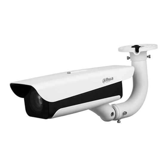
Summary of Contents for Dahua Technology DHI-ITC237-PW6M-LZF1050
- Page 1 Access ANPR Camera User's Manual ZHEJIANG DAHUA VISION TECHNOLOGY CO., LTD. V1.0.3...
-
Page 2: Foreword
The manual introduces the structure, installation, functions, and operations of the access ANPR camera (hereinafter referred to as "the Camera"). Models Model Description Focal Length Pixel DHI-ITC237-PW6M-LZF1050 DHI-ITC237-PW6M-IRLZF1050 10 mm–50 mm 2 MP DHI-ITC237-PW6M-IRLZF1050-B DHI-ITC237-PW6M-LZF1050-B Long Range Access ANPR Camera... - Page 3 User's Manual Signal Words Meaning Provides methods to help you solve a problem or save time. Provides additional information as a supplement to the text. Revision History Revision Content Release Time Revision Content V1.0.3 Updated manual format. October 2021 Updated the focal length of 437 and 415 V1.0.2 July 2021 models of camera.
-
Page 4: Important Safeguards And Warnings
User's Manual Important Safeguards and Warnings This section introduces content covering the proper handling of the device, hazard prevention, and prevention of property damage. Read carefully before using the device, comply with the guidelines when using it, and keep the manual safe for future reference. Transportation Requirements Transport the device under allowed humidity and temperature conditions. - Page 5 User's Manual ● Use the device under allowed humidity and temperature conditions. ● Do not drop or splash liquid onto the device, and make sure that there is no object filled with liquid on the device to prevent liquid from flowing into it. ●...
-
Page 6: Table Of Contents
User's Manual Table of Contents Foreword ........................................I Important Safeguards and Warnings ............................III 1 Introduction ......................................1 1.1 Overview ......................................1 1.2 Features ......................................1 2 Structure ........................................3 2.1 Long Range ANPR Camera Dimensions .......................... 3 2.2 Short Range ANPR Camera Dimensions ......................... 3 2.3 Structure ...................................... - Page 7 User's Manual 4.4.1.2 Image Downloading Attribute ........................26 4.4.1.3 PC Picture ................................27 4.4.2 Recording Search ................................27 4.4.2.1 Record ..................................27 4.4.2.2 Watermark ................................28 4.4.3 Capture Record Search ............................... 29 4.4.4 Alarm Output Search ..............................29 4.5 Setting ......................................30 4.5.1 ITC ......................................
- Page 8 User's Manual 4.5.2.1.1 General ................................. 48 4.5.2.1.2 Shutter ................................50 4.5.2.1.3 Metering Zone ............................51 4.5.2.2 Video ..................................52 4.5.2.2.1 Video ................................52 4.5.2.2.2 Snapshot ..............................53 4.5.2.2.3 Interest Area .............................. 54 4.5.3 Network ..................................... 55 4.5.3.1 TCP/IP ..................................55 4.5.3.2 Connection ................................
- Page 9 User's Manual 4.5.6.3.3 Firewall ................................. 78 4.5.6.4 Default Settings ..............................79 4.5.6.5 Import/Export ..............................79 4.5.6.6 Automatic Maintenance ..........................79 4.5.6.7 System Upgrade ..............................80 4.5.7 Information ..................................80 4.5.7.1 Version ..................................80 4.5.7.2 Log ..................................... 81 4.5.7.2.1 System Log ..............................81 4.5.7.2.2 Remote log ..............................
-
Page 10: Introduction
User's Manual 1 Introduction 1.1 Overview The access ANPR camera adopts intelligent deep learning algorithm. It supports vehicle detection, license plate recognition, logo recognition, model recognition, and color recognition, and encoding mode such as H.265. The Camera consists of protective housing, illuminator, and intelligent HD camera. The intelligent HD camera adopts progressive scanning CMOS, which owns several features such as high definition, low illuminance, high frame rate, and excellent color rendition. - Page 11 User's Manual Network Monitoring ● Transmits video data of single channel compressed by device to network terminal, and make it reappear after decompression through network. Keep delay within 500ms when bandwidth is allowed. ● Supports maximum 10 users online at the same time. ●...
-
Page 12: Structure
User's Manual 2 Structure 2.1 Long Range ANPR Camera Dimensions Figure 2-1 Camera dimensions (mm [inch]) Figure 2-2 Dimensions of camera with bracket (mm [inch]) 2.2 Short Range ANPR Camera Dimensions Figure 2-3 General camera dimensions (mm [inch]) -
Page 13: Structure
User's Manual Figure 2-4 Dimensions of camera with bracket (mm [inch]) Figure 2-5 Dimensions of camera with spherical bracket (mm [inch]) 2.3 Structure 2.3.1 Entire Device Figure 2-6 Entire device structure... -
Page 14: Rear Panel
User's Manual Table 2-1 Camera structure description Description Description Protective cover Lens Illuminator — 2.3.2 Rear Panel Figure 2-7 Rear panel structure Table 2-2 Description of rear panel structure Description Description Debugging port Hardware reset TF card — 2.4 Cable Connection Two cable connection methods are available, and might differ from the actual product. - Page 15 User's Manual Table 2-3 Cable connection description Port Function Description Connects to standard Ethernet, supports Ethernet port PoE power supply. The Camera sends out audio signal through AUDIO OUT Audio output port this port. The Camera gets audio signal through this AUDIO IN Audio input port port.
- Page 16 User's Manual Figure 2-9 Cable connection Table 2-4 Cable connection Port Function Description The Camera sends out audio signal through AUDIO OUT Audio output port this port. The Camera gets audio signal through this AUDIO IN Audio input port port. ●...
- Page 17 User's Manual Port Function Description ● Alarm output, connecting to barrier, and alarm output devices such as alarm light. Brown: ALARM_NO1 ◇ Green: ALARM_COM1 ◇ White & Purple: ALARM_NO2 ◇ Light Green: ALARM_COM2 ◇ Red: ALARM_NO3 ◇ ALARM Alarm port Black: ALARM_COM3 ◇...
-
Page 18: Installation
User's Manual 3 Installation The following installation figures are for reference only, and might differ from the actual product. 3.1 Universal Joint Installation Step 1 Use M6×14 screw to fix the universal joint on the bracket. Step 2 Use two 1/4-20×14UNC screws to fix the Camera on the universal joint. See . Figure 3-1 Universal joint installation Table 3-1 Camera structure description Description... - Page 19 User's Manual Figure 3-2 Prepare bracket housing Step 2 Cover the spherical bracket with bracket housing. Step 3 Use three M6×20 socket head cap screws to fix the bracket housing to the Camera. For the illustration after installation. Figure 3-3 Fix the bracket housing Figure 3-4 Installation completed...
-
Page 20: Web Configuration
User's Manual 4 Web Configuration It supports logging in to device web page through browser on PC, and realizes device configuration, operation, and management. The pages, and Settings are for reference only, and might differ from the actual page. 4.1 Web Login 4.1.1 Recommended Configuration Table 4-1 Recommended PC configuration PC Component... - Page 21 User's Manual Figure 4-1 Device Initialization Step 4 Enter Password, and Confirm Password. ● The new password must consist of 8 to 32 characters, and contain at least two types from upper case, lower case, number, and special characters (excluding ' " ; :, and &). ●...
- Page 22 User's Manual Figure 4-3 Login Enter the username, and password, and then click Login. Step 9 Prompt box will pop out when username or password is incorrect, see Figure 4-4, and it will remind you of remaining attempts. The account will be locked for 300 s if user enters incorrect username or password for 5 times consecutively.
-
Page 23: Login
User's Manual Figure 4-6 Web page It will pop out the prompt box of authorization failed when there is no operation on the web page for a long time. In this case, you need to log in again. Figure 4-7 Prompt 4.1.3 Login Step 1 You can log in to the web page by following the steps below. -
Page 24: Resetting Password
User's Manual ● A box pops up when the username or password is incorrect. ● If you enter invalid user name or password for five times, the account will be locked for 300 s. Figure 4-8 Invalid username or password 4.1.4 Resetting Password When you forgot your password, you can configure new password through the password reset function. - Page 25 User's Manual Figure 4-10 Information Step 3 Click OK. If you use IE browser, the system might prompt Stop running the script, click No, and continue to run the script. Step 4 Scan the QR code according to the page prompt, and send the scanning result to designated email, and acquire security code.
-
Page 26: Web Functions
User's Manual Figure 4-12 Reset password (2) Set Password, and enter your new password again in Confirm Password. Step 7 ● The new password must consist of 8 to 32 characters, and contain at least two types from upper cases, lower cases, numbers, and special characters (excluding ' " ; :, and &). ●... -
Page 27: Guide
User's Manual Button Description Recover the parameters to the value last saved. Save the settings. 4.2 Guide On the Guide page, you can configure capture scenarios, and get assistance with setting installation scenario. You can click at the upper-right corner of Guide page to exit. Step 1 Click the Guide tab. - Page 28 User's Manual 1) Drag zoom, and focus bar to adjust the video image properly. 2) When the vehicle plate comes into the green line area, click Snapshot to take a snapshot of the plate. Snapshot becomes Resume. 3) Drag the yellow plate pixel box to the position of the plate. 4) Click Zoom.
-
Page 29: Live
User's Manual Figure 4-18 Recognition Step 4 Configure recognition area. The configuration example on the right of video page can be used as a reference. 1) Click Iden Area(identification area). Click, and draw 4 lines on the video page, and the recognition area is formed. 2) Click Snap Line. -
Page 30: Video Stream
User's Manual 4.3.1 Video Stream ● Main Stream: Make sure that the Camera can record video, and carry out network surveillance when the network is normal. You can configure main stream resolution within the supported range of the Camera. ● Sub Stream: Replaces main stream to make network surveillance, and reduce the network bandwidth possession when network bandwidth is insufficient. -
Page 31: Logged Plate Number
User's Manual Icon Name Description Change the value when the image brightness is proper but Contrast contrast is not enough. The range is from 0 to 128 (64 by default). Adjust the image hue. For example, change red into blue. The default value is made by the light sensor, and normally it does not have to be adjusted. - Page 32 User's Manual Table 4-6 General function description Icons Name Description Select the check box, and the Camera automatically receives vehicle snapshots, and detects event information triggered by sources such as radar or video detection, and displays such ANPR Receive snapshots, and information at the lower part of the page. The snapshots are saved in the storage path defined by Setting >...
-
Page 33: Vehicle Snapshot
User's Manual The steps of config (LPR) are shown as follows. Step 1 Set focus, and zoom mode, which is used to recognize vehicle. Table 4-7 Focus parameter description Parameter Description Auto Focus Auto adjust camera lens, and make the scenario clearly focused. Click Regional, and then draw a box in the video image to focus the defined Regional region in the box. -
Page 34: Event List
User's Manual 4.3.8 Event List Select ANPR Receive, and the event information will be displayed, including No., event types, capture time, lanes, plates, vehicle color, speed, vehicle signs, and vehicle types. 4.4 Query Click the Query tab, and the system displays query page where you can search for pictures, and video recordings. -
Page 35: Image Downloading Attribute
User's Manual Parameter Description Select the Plate check box, take plate feature as query condition, and then inquire the pictures which conform to requirements. Plate You can also set some parameters of the plate to realize fuzzy query of plate number. Click Search, and it displays all the picture file lists which conform to query condition in Step 3 the file list. -
Page 36: Pc Picture
User's Manual Parameter Description ● Selected File: Select the needed picture (It supports selecting single picture or several pictures at the same time), click Download Mode Download, and the system will pop out the save dialog box. ● Selected Time: Click Download, and the system will automatically download all the pictures within the defined time. -
Page 37: Watermark
User's Manual Figure 4-26 Record Step 2 Click Browse, select record path, click Open, and view the video. Table 4-11 Play function description Icon Description ● : Play video. ● : Pause. Stop playing video. Slow down video playing. Speed up video playing. Skip to the next frame. -
Page 38: Capture Record Search
User's Manual Step 3 Click Watermark,and the system displays verify progress, normal watermark, and some other information. The page of Watermark Verification Completed appears after verification. 4.4.3 Capture Record Search Search for the vehicle record within the defined period, and according to the defined direction. ●... -
Page 39: Setting
User's Manual Figure 4-29 Alarm output search Click Export can export the search results to local. 4.5 Setting You can configure several parameters such as ITC, camera, network, event, storage, system, and system information. 4.5.1 ITC You can set intelligent parameters of the Camera. 4.5.1.1 Detection 4.5.1.1.1 Snapshot You can set snapshot rule of the Camera. - Page 40 User's Manual Step 2 Configure the parameters. Table 4-12 Description of capture parameters Parameter Description ● Loop: Use loop to take snapshots. ● Video: Use video to take snapshots. Work Mode ● Mixmode: Use loop and video to take snapshots. Number of Snapshots It can take 1–2 snapshot(s).
-
Page 41: Intelligence
User's Manual Table 4-13 Loop I/O parameters Parameter Description Only Loop I/O can be selected. Loop 1 Set the loop trigger mode. ● Not triggered: No capture is triggered. ● Rise Edge: Capture is triggered when the vehicle enters loop. Trigger Mode Config ●... -
Page 42: Scene
User's Manual Figure 4-32 Recognition Step 2 Configure parameters. Table 4-14 Recognition parameters description Parameter Description Car Series Select the target of recognition according to your requirements. Vehicle Sign Vehicle Brand Overseas car series not supported. Vehicle Color Same Plate Filtering Time One plate can be captured once within the defined period. -
Page 43: Advance Configuration
User's Manual Step 2 Select detection scene as needed. ● Head first: Higher recognition sensitivity towards plate on head. ● Tail first: Higher recognition sensitivity towards plate on tail. ● Bicycle (electric bicycle or motorcycle): Higher recognition sensitivity towards electric bicycle or motorcycle plate. - Page 44 User's Manual Figure 4-35 Video OSD Step 2 Select font size. Step 3 Set channel title, and coordinates. 1) Click Channel Title. 2) Select On. 3) Enter channel name. 4) Drag the yellow box or enter coordinate directly to set the location of channel title. Step 4 Set time title, and location.
-
Page 45: Snap Osd
User's Manual Figure 4-37 Custom The system supports up to 6 customized regions. Step 6 Click Confirm. 4.5.1.3.2 Snap OSD You can set OSD information of pictures. Step 1 Select Setting > ITC > OSD > Snapshot OSD. Figure 4-38 Snap OSD Step 2 Move the title box to displayed location, or manually enter coordinate value into the X/Y box in the lower-right corner of the page. -
Page 46: Cutout Configuration
User's Manual Figure 4-39 New line, and OSD separator Select the NewLine check box as needed, and then set separator types of OSD Step 6 information. You can manually enter other separators when selecting Custom from Osd Separator. Step 7 Set OSD options. -
Page 47: Face Overlap
User's Manual 4.5.1.4.2 Face Overlap In this section, you can select whether to overlap the face image of the driver and assistant driver onto the snapshot, and the overlap position and size. Step 1 Select Setting > ITC > Cutout > Face Overlap. Step 2 Configure the parameters as needed. -
Page 48: Allowlist
User's Manual Table 4-17 Allowlist parameters description Parameter Description Plate number will be matched when the first or last character of Lost 1 Character at The Ends the detected plate is missing. Plate number will be matched when one more character is Redundant 1 Character at detected before the first character or after the last character of the Ends... - Page 49 User's Manual Figure 4-44 Add 2) Enter complete plate number, and card ID. 3) Set the Begin Time, and End Time of the plate number which exists in allowlist. The vehicle will be no longer considered as allowlist vehicle beyond the defined time range.
-
Page 50: Blocklist Search
User's Manual 1) Click Template to download the template, or open the .csv file you exported, fill in the allowlist data which needs to be imported according to template format, and then save the file. 2) Click Browse…, and select the path where template file exists. 3) Click Import, and you can import the allowlist data into the system in batches. -
Page 51: Rs-485
User's Manual Table 4-18 Barrier control parameter description Parameter Description Select it, and enable the function of barrier always open. Configure Barrier Always Open the period of barrier always open. The barrier will not close during the defined period. Select it to enable barrier control, and configuration. Triggers alarm through different modes, and remotely controls the barrier opening and close. - Page 52 User's Manual Table 4-19 DHRS parameters description Parameter Description Data Bit 8 by default, and cannot change. Stop Bit 1 by default, and cannot change. The transmission speed of the code element. Options are 4800, Baud Rate 9600, 19200, 38400, 115200. Check None by default, and cannot change.
-
Page 53: Rs-485 Led Display
User's Manual Parameter Description Common Click to restore to commonly selected fields (default). Config Up/Down Click to move the field position up or down. Tag Head The tag head of data package. It is aabb by default. Tag Tail The tag tail of data package. It is aa55 by default. Encode General config Select encode type from UTF-8 (default) and GB2312. -
Page 54: Voice Broadcast
User's Manual Parameter Description Drawing Type Select display type from 2 × 2, 2 × 1, and 4 × 1. ● Rolling Speed: The rolling speed of the information on LED, including Slow, Slightly Slow, Medium, Slightly Fast (default), and Fast. Full Screen ●... -
Page 55: Volume/Encoding
User's Manual Step 3 Configure parameters. Table 4-22 Broadcast content parameters description Parameter Description Insert Before Insert an option before the selected one on the display area. Insert After Insert an option after the selected one on the display area. Click next to the broadcast option to edit the prefix, and suffix of the Edit... -
Page 56: Capturing Commissioning
User's Manual device information. Select Setting > ITC > Device Test > Device Test. Step 1 Figure 4-54 Device test Step 2 Configure parameters. Table 4-23 Device test parameter description Parameter Description Barrier Opening, and Closing Click Open or Close to test the barrier. Click Test to stimulate capture, and view the snapshot in Live Capture page. -
Page 57: Camera
User's Manual Figure 4-55 Capturing commissioning Step 3 Click Confirm. Step 4 Go to Live page, and then click to manually capture plate. On the snapshot, you can see the selected line information, and you can adjust the capture line, and others as needed. - Page 58 User's Manual Table 4-24 General parameters description Parameter Description Adjust the overall image brightness. Change the value when the image is too bright or too dark. The bright, and dark areas will have equal changes. The image becomes blurry Brightness when the value is too big.
-
Page 59: Shutter
User's Manual Parameter Description Illumination Intensity Set the illumination intensity when there are vehicles passing. when Vehicles Pass Step 3 Click Confirm. 4.5.2.1.2 Shutter This section provides guidance on configuring camera shutter, including shutter mode, exposure mode, gain mode, and scene mode. Step 1 Select Setting >... -
Page 60: Metering Zone
User's Manual Parameter Description Select the way of adjusting exposure mode. You can select from Mode Manual, and Auto. Shutter You need to set shutter when set Mode to Manual. Set the time range of shutter. Shutter Scope You need to set shutter when Customized Range is set as Shutter. Set the value range of gain. -
Page 61: Video
User's Manual Parameter Description ● Global Measure: Measure the brightness of the whole image area, and intelligently adjust the overall image brightness. ● Partial Measure: Measure the brightness of sensitive area, and Measure Mode intelligently adjust the overall image brightness. If the measured area becomes bright, then the whole area becomes dark, and vice versa. -
Page 62: Snapshot
User's Manual Parameter Description The value is the upper limit of the stream in VBR mode Bit Rate while it is fixed in CBR mode. Frame or time interval between two I frames. The bigger the interval, the smaller space taken by the I Frame Interval decompressed video. -
Page 63: Interest Area
User's Manual Parameter Description Image Size It is in accordance with resolution value. Quality Set the snapshot quality which includes 6 levels optional. Select picture coding size from 8 options, or select Custom to define the size (50–1024). Picture Coding Size (KB) You can only select one between picture quality and picture coding size to set the configuration. -
Page 64: Network
User's Manual Parameter Description Clear Delete all the configured regions. Delete the latest ROI. You can click it for several times. Right-click any position Delete in the image to realize the same effect. Step 3 Click Confirm. 4.5.3 Network You can set IP address, port, and other parameters. 4.5.3.1 TCP/IP Configure the IP address of the Camera, and DNS server so that the Camera can connect with other devices in the network. -
Page 65: Connection
User's Manual Parameter Description Network mode, including static, and DHCP. ● Static: Manually set IP, subnet mask, and gateway. Mode ● DHCP: Automatically acquire IP. At this moment, IP, subnet mask, and gateway cannot be set. MAC Address MAC address of the host. Includes IPv4, and IPv6. -
Page 66: Onvif
User's Manual Parameter Description HTTP Port HTTP communication port. It is 80 by default. RTSP Port Media streaming control port. It is 554 by default. HTTPS Port HTTPS communication port. It is 443 by default. Click Confirm. Step 3 4.5.3.2.2 ONVIF You can enable the Open Network Video page Forum (ONVIF) function to make network video products of different manufacturers interworking. -
Page 67: Smtp (Email)
User's Manual Figure 4-65 Auto register Step 3 Configure parameters. Table 4-32 Auto register parameter description Parameter Description Address The IP address of the server on which the device register. Port The port of the server for auto registration. The device ID distributed by the server for auto registration. Make sure Sub-Device ID that the ID is unique during auto registration. - Page 68 User's Manual Figure 4-66 SMTP (email) Step 2 Configure parameters. Table 4-33 SMTP (Email) parameter description Parameter Description SMTP Server IP address of the outgoing mail server that complies with SMTP protocol. Port number of the outgoing mail server complying with SMTP protocol. Port It is 25 by default.
-
Page 69: Ieee802
User's Manual Parameter Description The system sends test mail to check whether the connection succeeds. Health Mail Select the Health Mail check box, and configure the Update Period, and then the system sends test mails according to the defined period. Test whether the email function is normal. -
Page 70: Itc Push
User's Manual 4.5.3.6 ITC Push You can configure this parameter to push the captured vehicle violations information to the server. Step 1 Select Setting > Network > ITCPUSH. Figure 4-68 ITC push configuration Step 2 Configure parameters. Table 4-35 ITC push parameter description Parameter Description Select On check box to push passing vehicles information. -
Page 71: Event
User's Manual 4.5.4 Event This section provides guidance on configuring alarm, and abnormality. 4.5.4.1 Alarm 4.5.4.1.1 Relay Activation You can set several parameters of relay activation such as relay-in, period, anti-dither, and sensor type. When triggering alarm, the system sends the alarm signal to external devices to trigger, for example, buzz. -
Page 72: Relay-Out
User's Manual 2) Click Setup corresponding to the day you need to configure time period. 3) Select the period you need to enable, and enter start time, and end time of corresponding period. 4) If you need to apply this period setting to any other day, select the check box of corresponding days. -
Page 73: Abnormality
User's Manual 4.5.4.2 Abnormality Set relay-out mode of different events. When abnormality happens, system triggers alarm. Step 1 Select Setting > Event > Abnormality. Step 2 Select events from SD card, network error, illegal access, security exception and blocklist car as needed. Figure 4-72 No storage card Step 3 (Optional) Select event type. -
Page 74: Point
User's Manual 4.5.5.1 Point Set the storage path of snapshot. Step 1 Select Setting > Storage > Destination > Point. Figure 4-73 Point Step 2 Select Event Type. ● Local: Store into the TF card. ● FTP: Store into the FTP server. Step 3 Click Confirm. -
Page 75: Ftp
User's Manual 4.5.5.3 FTP FTP function can be enabled only when it is selected as destination path. When the network does not work, you can save all the files to the internal SD card for emergency. You can set picture name, and storage path. Click Help... to view naming rule. Select Setting >... -
Page 76: Client
User's Manual Parameter Description Refers to the encode mode of Chinese characters when naming pictures. Two modes are available: UTF-8, and GB2312. After configuring Server IP, Encode Type and Port, click test to check whether the FTP server works. Port The port number of FTP server. -
Page 77: System
User's Manual Step 1 Select Setting > Storage > Destination > Save Path. Figure 4-77 Storage path Step 2 According to your actual requirement, set the name of picture, and storage path. See Help... for more details. Step 3 Set the root path for recordings and snapshots. Click Confirm. -
Page 78: Date & Time
User's Manual Table 4-40 General parameters description Parameter Description Device SN The ID number of the Camera. Supports English letters, and numbers. Device Code Device Code Failed to support OSD information overlay. The language displayed on web. The language will be automatically Language switched after logging in web again. -
Page 79: Account
User's Manual Parameter Description Set current system time of the Camera. It becomes valid immediately System Time after setting. Sync PC Sync the time of the Camera with the time on PC. Enable the function, and then set begin time, and end time of DST according to date or week. - Page 80 User's Manual Figure 4-81 Add user Step 3 Configure parameters. Table 4-42 Add user parameters description Parameter Description Username It can only consist of number, letter, underline, and hyphen, the Username maximum length contains 15 characters, and it cannot be the same as the existed username.
-
Page 81: Onvif User
User's Manual ● The system supports max 8 user groups, and the default initialization user groups are admin, and user. ● You can modify, and delete the added user group, but not the initialization user group. Figure 4-82 User group Step 6 Click Add Group, and then enter the name of user group, and configure group authority. - Page 82 User's Manual page. Select Setting > System > Account > Onvif User. Step 1 Figure 4-84 Onvif user Step 2 Click Add User. Figure 4-85 Add user Step 3 Configure parameters. Table 4-43 User parameter description Parameter Description Username The unique identification of user. You cannot use existing user name. Password The password of user, and confirm password.
-
Page 83: Safety
User's Manual 4.5.6.3 Safety 4.5.6.3.1 System Service Select to enable system services as needed. Select Setting > System > Safety > System Service. Step 1 Figure 4-86 System Service Step 2 Select needed system service. Table 4-44 System service parameters description Parameter Description SSH (Secure Shell) implements data encrypted transmission, and... -
Page 84: Https
User's Manual 4.5.6.3.2 HTTPS Prerequisites ● For first-time use of HTTPS or after changing device IP address, you need to create server certificate, and install root certificate. ● After creating server certificate, and installing root certificate, if it replaces the PC, which logs in to the web page, then it needs to download, and install the root certificate again on the new PC or copy the downloaded root certificate on the new PC, and install. - Page 85 User's Manual 3. Enter the required information such as region, IP or domain name, and then click Create. The entered IP or Domain name must be the same as the IP or domain name of the Camera. 4. Click Install under Request Created, and then click Download to download root certificate.
- Page 86 User's Manual Figure 4-90 Certificate store 8. Click Next. Figure 4-91 Completing certificate import wizard 9. Click Finish. Figure 4-92 Security warning...
-
Page 87: Firewall
User's Manual 10. Click Yes, and then click OK on the pop-up window. ● If you select install signed certificate, follow the steps below. 1. Select Setting Safety > System > Safety > HTTPS. 2. Select Enable HTTPS, and Compatible with TLSv1.1, and earlier versions. 3. -
Page 88: Default Settings
User's Manual 4.5.6.4 Default Settings You can restore the device to default settings or factory defaults. Select Setting > System > Default, and then select Default or Factory Default as needed. ● Default: Restore your settings to default value. In this case, network IP address information of the Camera will not restore to default settings. -
Page 89: System Upgrade
User's Manual Table 4-45 Auto maintain parameter description Parameter Description ● Select, and set restart period, and time. Auto Reboot ● The system will automatically restart within the defined period, and time. Auto Delete Old Files Customize time, and delete all the old files before the time. Manual Reboot Manually restart the Camera. -
Page 90: Log
User's Manual ● Versions of different devices might vary, depending on the actual web page. ● Algorithm recognition is available when algorithm is authorized (when the icon is displayed in green). If algorithm is not authorized, the Camera will not be able to recognize vehicle series, model, and logo. -
Page 91: Remote Log
User's Manual Backup: Backup the searched system log information to local. The backup file is in .txt format. 4.5.7.2.2 Remote log You can save your important logs to log server. This helps provide important clues to the source of security incidents. Log server needs to be deployed in advance by a professional or system administrator. -
Page 92: Online User
User's Manual Step 5 Click Confirm. 4.5.7.3 Online User Select Setting > Information > Online User to view the information of all the online users. Figure 4-103 Online user Click Refresh to view the latest status. 4.5.7.4 Running Status Select Setting > Information > Running Status to view the system running time. Figure 4-104 Running status 4.6 Alarm Click the Alarm tab, and then you can select alarm type, operation, and alarm tone. -
Page 93: Logout
User's Manual Figure 4-105 Alarm Table 4-46 Alarm parameters description Type Parameter Description Storage Full It triggers alarm when storage card is full. Storage Error It triggers alarm when storage card fault occurs. It generates alarm through peripheral device when External Alarm alarm is triggered. -
Page 94: Faq
User's Manual 5 FAQ Question Solution Device error, unable to start or Press, and hold Reset button for 5 seconds to restore the operate normally Camera to factory default Settings. Stop recording, and image capturing, and then wait for at least TF card hot swapping 15 seconds before removing the TF card. -
Page 95: Appendix 1 Cybersecurity Recommendations
User's Manual Appendix 1 Cybersecurity Recommendations Cybersecurity is more than just a buzzword: it’s something that pertains to every device that is connected to the internet. IP video surveillance is not immune to cyber risks, but taking basic steps toward protecting and strengthening networks and networked appliances will make them less susceptible to attacks. - Page 96 User's Manual 1024–65535, reducing the risk of outsiders being able to guess which ports you are using. 6. Enable HTTPS We suggest you to enable HTTPS, so that you visit Web service through a secure communication channel. 7. MAC Address Binding We recommend you to bind the IP and MAC address of the gateway to the device, thus reducing the risk of ARP spoofing.
- Page 97 User's Manual device. More information Please visit Dahua official website security emergency response center for security announcements and the latest security recommendations.
- Page 98 User's Manual...
Need help?
Do you have a question about the DHI-ITC237-PW6M-LZF1050 and is the answer not in the manual?
Questions and answers