
Related Manuals for Dahua Technology D-ITC237-PW6M-IRLZF1050-B


Summary of Contents for Dahua Technology D-ITC237-PW6M-IRLZF1050-B
- Page 1 Access ANPR Camera User’s Manual ZHEJIANG DAHUA VISION TECHNOLOGY CO., LTD. V2.0.0...
-
Page 2: Foreword
User’s Manual Foreword General The manual introduces the structure, installation, functions, and operations of the access ANPR camera (hereinafter referred to as "the Camera"). Models Model Description Focal Length Pixel DHI-ITC237-PW6M-LZF1050 DHI-ITC237-PW6M-IRLZF1050 Long Range Access 10 mm–50 mm 2 MP ANPR Camera DHI-ITC237-PW6M-IRLZF1050-B DHI-ITC237-PW6M-LZF1050-B... - Page 3 User’s Manual Revision History Version Revision Content Release Time V2.0.0 Updated some interfaces, and functions under ITC. November 2020 V1.0.1 Added more models, and the SMTP function. May 2020 V1.0.0 First release. November 2019 About the Manual The manual is for reference only. If there is inconsistency between the Manual, and the actual product, the actual product shall prevail.
-
Page 4: Important Safeguards And Warnings
User’s Manual Important Safeguards and Warnings This section describes the contents covering proper handling of the Camera, hazard prevention, and prevention of property damage. Read these contents carefully before using the Camera, comply with them when using, and keep the manual well for future reference. Power Requirements ... - Page 5 User’s Manual there is condensed fog found on the lens after unpacking or when the desiccant turns green. (Not all models are included with the desiccant). It is recommended to use the Camera together with lightning arrester to improve lightning protection effect.
-
Page 6: Table Of Contents
User’s Manual Table of Contents Foreword ..............................I Important Safeguards, and Warnings ....................III 1 Introduction ............................1 1.1 Overview ............................1 1.2 Features ............................1 2 Structure ..............................3 2.1 Long Range ANPR Camera Dimensions ..................3 2.2 Short Range ANPR Camera Dimensions ..................3 2.3 Structure ............................ - Page 7 User’s Manual 4.5.4 Event ..........................65 4.5.5 Storage ..........................68 4.5.6 System ..........................72 4.5.7 Information ........................90 4.6 Alarm ............................93 4.7 Logout ............................94 5 FAQ ............................... 95 Appendix 1 Cybersecurity Recommendations ................... 96...
-
Page 8: Introduction
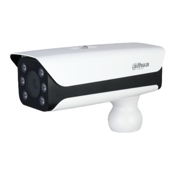
User’s Manual Introduction 1.1 Overview The access ANPR camera adopts intelligent deep learning algorithm. It supports vehicle detection, license plate recognition, logo recognition, model recognition, and color recognition, and encoding mode such as H.265. The Camera consists of protective housing, illuminator, and intelligent HD camera. The intelligent HD camera adopts progressive scanning CMOS, which owns several features such as high definition, low illuminance, high frame rate, and excellent color rendition. - Page 9 User’s Manual linkage predefined by users, and generate corresponding voice prompt (users are allowed to record voice in advance). Network Monitoring Transmits video data of single channel compressed by device to network terminal, and make it reappear after decompression through network. Keep delay within 500ms when bandwidth is allowed.
-
Page 10: Structure
User’s Manual Structure 2.1 Long Range ANPR Camera Dimensions Figure 2-1 Camera dimensions (mm [inch]) Figure 2-2 Dimensions of camera with bracket (mm [inch]) 2.2 Short Range ANPR Camera Dimensions Figure 2-1 General camera dimensions (mm [inch]) -
Page 11: Entire Device
User’s Manual Figure 2-2 Dimensions of camera with bracket (mm [inch]) Figure 2-3 Dimensions of camera with spherical bracket (mm [inch]) 2.3 Structure 2.3.1 Entire Device Figure 2-4 Entire device structure... -
Page 12: Rear Panel
User’s Manual Table 2-1 Camera structure description Description Description Protective cover Lens Illuminator — — 2.3.2 Rear Panel Figure 2-5 Rear panel structure Table 2-2 Description of rear panel structure Description Description Debugging port Hardware reset TF card — — 2.4 Cable Connection Two cable connection methods are available, and the actual product shall prevail. - Page 13 User’s Manual Table 2-3 Cable connection description Port Function Description Connects to st, andard Ethernet, supports PoE Ethernet port power supply. The Camera sends out audio signal through this AUDIO OUT Audio output port port. AUDIO IN Audio input port The Camera gets audio signal through this port.
-
Page 14: Short Range Anpr Camera Dimensions
User’s Manual Figure 2-7 Cable connection Table 2-4 Cable connection Port Function Description The Camera sends out audio signal through this AUDIO OUT Audio output port port. AUDIO IN Audio input port The Camera gets audio signal through this port. White &... -
Page 15: Structure
User’s Manual Port Function Description Inputs 24V AC power. Be sure to supply power as instructed. 24V AC Power input port Device damage will occur if power is not supplied correctly. Connects to st, andard Ethernet. Supports PoE Ethernet port power supply. -
Page 16: Installation
User’s Manual Installation The following installation figures are for reference only, and the actual product shall prevail. 3.1 Universal Joint Installation Step 1 Use M6×14 screw to fix the universal joint on the bracket. Step 2 Use two 1/4-20×14UNC screws to fix the Camera on the universal joint. See Figure 3-1. -
Page 17: Bracket Installation
User’s Manual 3.2 Bracket Installation Figure 3-2 Bracket installation Table 3-2 Bracket installation Description Adjust the Camera leftward, and rightward. Adjust the Camera upward, and downward. Adjust the Camera horizontally. Step 1 Loosen the No. 1, and No. 3 screws shown in Figure 3-2. Step 2 Insert all the camera cables into the bracket, and then pull them out from the bracket tail. - Page 18 User’s Manual Figure 3-3 Prepare bracket housing Step 2 Cover the spherical bracket with bracket housing. Step 3 Use three M6×20 socket head cap screws to fix the bracket housing to the Camera. See Figure 3-4. For the illustration after installation, see Figure 3-5. Figure 3-4 Fix the bracket housing...
- Page 19 User’s Manual Figure 3-5 Installation completed...
-
Page 20: Web Configuration
User’s Manual Web Configuration It supports logging in to device web interface through browser on PC, and realizes device configuration, operation, and management. The interfaces, and Settings are for reference only, and the actual interface shall prevail. 4.1 Web Login 4.1.1 Recommended Configuration Refer to Table 4-1 for recommended PC configuration for logging in to the web interface of the Camera. - Page 21 User’s Manual Figure 4-1 Device Initialization Step 4 Enter Password, and Confirm Password. The new password must consist of 8 to 32 characters, and contain at least two types from upper case, lower case, number, and special characters (excluding ' "...
- Page 22 User’s Manual Figure 4-3 Login Step 9 Enter the username, and password, and then click Login. The web interface is displayed. Prompt box will pop out when username or password is incorrect, see Figure 4-4, and it will remind you of remaining attempts. The account will be locked for 300 s if user enters incorrect username or password for 5 times consecutively.
-
Page 23: Login
User’s Manual After installation is completed, the web interface is displayed. See Figure 4-6. Figure 4-6 Web interface It will pop out the prompt box of authorization failed when there is no operation on the web interface for a long time. In this case, you need to log in again. Figure 4-7 Prompt 4.1.3 Login You can log in to the web interface by following the steps below. -
Page 24: Resetting Password
User’s Manual Figure 4-8 Invalid username or password 4.1.4 Resetting Password When you forgot your password, you can configure new password through the password reset function. When scanning QR code to acquire security code, one QR code supports security code acquisition up to twice. - Page 25 User’s Manual Figure 4-10 Information Step 3 Click OK. If you use IE browser, the system might prompt Stop running the script, click No, and continue to run the script. Figure 4-11 Reset password (1) Step 4 Scan the QR code according to the interface prompt, and send the scanning result to designated email, and acquire security code.
-
Page 26: Web Functions
User’s Manual Figure 4-12 Reset password (2) Step 7 Set Password, and enter your new password again in Confirm Password. The new password must consist of 8 to 32 characters, and contain at least two types from upper cases, lower cases, numbers, and special characters (excluding ' " ; :, and &). The new password must be the same as the Confirm Password. -
Page 27: Guide
User’s Manual Table 4-3 Common buttons description Button Description Restore all parameters to system defaults. Recover the parameters to the value last saved. Save the settings. 4.2 Guide On the Guide interface, you can configure capture scenarios, and get assistance with setting installation scenario. - Page 28 User’s Manual Figure 4-15 Plate pixel Step 3 You can check whether the video image is properly zoomed, and focused by checking the plate pixel. Drag zoom, and focus bar to adjust the video image properly. When the vehicle plate comes into the green line area, click Snapshot to take a snapshot of the plate.
- Page 29 User’s Manual Figure 4-16 Plate pixel size Click Check Pixel. Figure 4-17 Check plate Click Yes, and plate pixel configuration is finished. Figure 4-18 Recognition Step 4 Configure recognition area. The configuration example on the right of video interface can be used as a reference. Click Iden Area (identification area).
-
Page 30: Live
User’s Manual Click Save to complete the Settings. Step 5 Click Finish, exit Guide interface, and enter Live interface. 4.3 Live Click the Live tab. The Live interface is displayed. On this interface, it can realize several functions such as live video, live picture, real-time capture, record, and config (LPR), and more. - Page 31 User’s Manual : Adjust the image to original size or appropriate window. : Click it to switch to big window, and click on the lower-left corner to display image adjustment window. Click it again to exit big window. Figure 4-20 Big window : Click it to open image adjustment window on the right, meanwhile the button ...
-
Page 32: Logged Plate Number
User’s Manual Icon Name Description Change the value when the image brightness is proper but Contrast contrast is not enough. The range is from 0 to 128 (64 by default). Adjust the image hue. For example, change red into blue. The default value is made by the light sensor, and normally it does not have to be adjusted. - Page 33 User’s Manual Table 4-6 General function option Icons Name Description Select the check box, and the Camera automatically receives vehicle snapshots, and detects event information triggered by ANPR sources such as radar or video detection, and displays such Receive snapshots, and information at the lower part of the interface. The snapshots are saved in the storage path defined by Setting >...
- Page 34 User’s Manual Figure 4-22 Config (LPR) The steps of config (LPR) are shown as follows. Step 1 Set focus, and zoom mode, which is used to recognize vehicle. Refer to Table 4-7 for more details. Table 4-7 Focus parameter description Parameter Description Auto Focus Auto adjust camera lens, and make the scenario clearly focused.
-
Page 35: Vehicle Snapshot
User’s Manual Table 4-8 Line parameters description Parameter Description Click it, and draw the area range which needs to be detected. Iden Area The recognition area line is displayed as red box. Draw the detection line which triggers video capture, it is as functional as the line in traffic. -
Page 36: Query
User’s Manual 4.4 Query Click the Query tab, and the system displays query interface where you can search for pictures, and video recordings. 4.4.1 Image Search 4.4.1.1 SD Picture Search conditions can be set in this section. You can search for event, and plate information of the SD card within the period. - Page 37 User’s Manual Step 4 Download picture. Click to select pictures, and then click Download. Step 5 Set the storage path of picture in the prompted window. The system starts to download the pictures to local PC. Click Open or double-click the picture if you need to view the picture. If several pictures are selected at the same time, click Open to view all the pictures.
-
Page 38: Recording Search
User’s Manual Parameter Description Restore Restore the picture name to default. Help… View the naming rule of downloaded pictures. Step 3 Click Confirm. 4.4.1.3 PC Picture The section introduces the way of checking whether the watermark of PC picture is tampered. Step 1 Select Query >... - Page 39 User’s Manual Figure 4-26 Record Step 2 Click Browse, select record path, click Open, and view the video. For the function description of video play button, see the table below. Table 4-11 Play function Icon Description : Play video. : Pause.
-
Page 40: Capture Record Search
User’s Manual Figure 4-27 Watermark Step 2 Click Browse, and select a file that you want to verify. Step 3 Click Watermark, and the system displays verify progress, normal watermark, and some other information. The interface of Watermark Verification Completed appears after verification. 4.4.3 Capture Record Search Search for the vehicle record within the defined period, and according to the defined direction. -
Page 41: Alarm Output Search
User’s Manual Step 2 Set Begin Time, and End Time, and then set the Direction (vehicle movement direction, including Approaching, Departing, and Unknown). Step 3 Click Search to search for the plates that meet the search conditions. Step 4 Click Export, and then select storage path to export the results to PC. 4.4.4 Alarm Output Search Set the search conditions to search alarm output. - Page 42 User’s Manual Step 1 Select Setting > ITC > Detection > Snapshot. Figure 4-30 Snapshot Step 2 Configure the parameters. Table 4-12 Description of capture parameters Parameter Description Loop: Use loop to take snapshots. Work Mode Video: Use video to take snapshots. Mixmode: Use loop and video to take snapshots.
- Page 43 User’s Manual Parameter Description Max Pass Time: Configure the maximum time for vehicle passing. 5 s (default) means that under loop mode, the capture will not take Loop Mode snapshots when both loops are triggered within 5 s interval. Parameters Loop Cache Frame: Configure the cache frame number of loop.
- Page 44 User’s Manual Set IO snapshot scheme. Single_in_1: Lay single loop, and it will take snapshot when the vehicle enters loop. Scheme Double_in_1: Lay double loops, and it will take snapshot when the vehicle enters the first loop. Double_in_2: Lay double loops, and it will take snapshot ...
- Page 45 User’s Manual Table 4-14 Recognition parameters description Parameter Description Car Series Select the target of recognition according to your requirements. Vehicle Sign Vehicle Br, and Overseas car series not supported. Vehicle Color Same Plate Filtering One plate can be captured once within the defined period. Time Vehicle Detection Set the sensitivity of vehicle detection.
- Page 46 User’s Manual Figure 4-34 Advanced configuration Step 2 Configure parameters. Table 4-15 Advanced configuration parameter description Parameter Description Custom Algorithm Enter custom algorithm for advanced function. Click to view advanced algorithm formula. 4.5.1.3 OSD Configuration Set the overlapping OSD (On-screen Display) information on video and image. 4.5.1.3.1 Video OSD Set OSD information of video channel.
- Page 47 User’s Manual Figure 4-35 Video OSD Step 2 Select font size. Step 3 Set channel title, and coordinates. Click Channel Title. Select On. Enter channel name. Drag the yellow box or enter coordinate directly to set the location of channel title. Step 4 Set time title, and location.
- Page 48 User’s Manual Figure 4-37 Custom The system supports up to 6 customized regions. Step 6 Click Confirm. 4.5.1.3.2 Snap OSD You can set OSD information of pictures. Step 1 Select Setting > ITC > OSD > Snapshot OSD. Figure 4-38 Snap OSD Step 2 Move the title box to displayed location, or manually enter coordinate value into the X/Y box in the lower-right corner of the interface.
- Page 49 User’s Manual Figure 4-39 New line, and OSD separator Step 6 Select the NewLine check box as needed, and then set separator types of OSD information. You can manually enter other separators when selecting Custom from Osd Separator. Step 7 Set OSD Option. Table 4-16 Snap OSD parameters description Parameter Description Insert...
- Page 50 User’s Manual Figure 4-40 Snap cutout Step 2 Select On, and select Plate or Whole Vehicle, and then the function of plate cutout or whole vehicle cutout is enabled. Step 3 Click Confirm. 4.5.1.5 Blocklist and Allowlist 4.5.1.5.1 Fuzzy Matching Enable fuzzy match, and set the fuzzy match conditions.
- Page 51 User’s Manual Step 2 Select the Enable check box to enable fuzzy match, and then configure the parameters as needed. Table 4-17 Allowlist parameters description Parameter Description Lost Plate number will be matched when the first or last character of the detected Character at plate is missing.
- Page 52 User’s Manual Delete single plate number: Click of the corresponding plate number searched, and delete it from the allowlist. Delete plate number in batches: click Clear All, and then click Confirm in the dialog box to delete all the allowlist information. Adding vehicles to allowlist one by one: ...
- Page 53 User’s Manual Figure 4-44 Encrypt config Select the path of storing files. Click Save, and export allowlist to local in .csv format, which can be opened in Excel. Importing vehicles to allowlist in batches: Click Template to download the template, or open the .csv file you exported, fill in the allowlist data which needs to be imported according to template format, and then save the file.
- Page 54 User’s Manual 4.5.1.5.4 Barrier Control You can set the barrier control mode, and configure information of opening, and closing barrier. Step 1 Select Setting > ITC > Blocklist and Allowlist > Barrier Control. Figure 4-46 Barrier control Step 2 Configure parameters.
- Page 55 User’s Manual Table 4-18 Barrier control parameter description Parameter Description Select it, and enable the function of barrier always open. Configure the Barrier period of barrier always open. The barrier will not close during the defined Always Open period. Select it to enable barrier control, and configuration. Triggers alarm through different modes, and remotely controls the barrier opening and close.
- Page 56 User’s Manual Figure 4-47 DHRS parameters Table 4-19 DHRS parameters description Parameter Description Data Bit 8 by default, and cannot change. Stop Bit 1 by default, and cannot change. The transmission speed of the code element. Options are 4800, 9600, Baud Rate 19200, 38400, 115200.
- Page 57 User’s Manual Figure 4-49 Serial port push Table 4-20 Serial port push parameter description Parameter Description Quick Field Name Select fields to send to the third serial collection configuration device. Hover over the fields, you can see the explanations. Select the checkbox next to Field Name to select all the fields.
- Page 58 User’s Manual Figure 4-50 RS-485 LED display Step 2 Configure LED parameters. Table 4-21 LED parameters description Parameter Description Entrusting Select On, and then the LED will be totally controlled by superior platform. Mode The protocol must be supported by the platform. Working Platform Mode: Select this to allow platform to control LED display ...
- Page 59 User’s Manual 4.5.1.8 Voice Broadcast You can configure the voice broadcast content, volume, and encoding of the ANPR camera. 4.5.1.8.1 Broadcast Content Configure the broadcast content, and the Camera will broadcast the content when vehicles passing. Some devices do not support voice. Step 1 Select Setting >...
- Page 60 User’s Manual 4.5.1.8.2 Volume/Encoding Configure the volume of voice broadcast. Step 1 Select Setting > ITC > Voice Broadcast > Volume/Encoding. Step 2 Configure the input volume, output volume, and speaking speed as needed. Figure 4-52 Volume/Encoding Step 3 Click Confirm. 4.5.1.9 Device Test 4.5.1.9.1 Device Test You can test the barrier opening, and closing, capture, display content, voice broadcast, and...
- Page 61 User’s Manual Figure 4-53 Device test Step 2 Configure parameters. Table 4-23 Device test parameter description Parameter Description Barrier Opening, Click Open or Close to test the barrier. and Closing Capture Click Test to stimulate capture, and view the snapshot in Live interface. Display Content Click Test, and view whether the LED screen displays as configured.
-
Page 62: Camera
User’s Manual Figure 4-54 Capturing commissioning Step 3 Click Confirm. Step 4 Go to Live interface, and then click to manually capture plate. On the snapshot, you can see the selected line information, and you can adjust the capture line, and others as needed. - Page 63 User’s Manual Figure 4-55 General settings Step 2 Configure parameters. Table 4-24 General parameters description Parameter Description Adjust the overall image brightness. Change the value when the image is too bright or too dark. The bright, and dark areas will have equal changes. The image becomes blurry Brightness when the value is too big.
- Page 64 User’s Manual Parameter Description Brightness Prevalue of brightness. You can drag the slider to adjust the value. The higher Prevalue the value, the brighter the video image. Always Off: Set the IR light to always on. Always On: Set the IR light to always off. ...
- Page 65 User’s Manual Parameter Description Video Temporal video denoising. The higher the value, the fewer the flicker noise. Temporal Picture You can change the scene, and adjust the sharpness of corresponding Scene scene. Scenes available: Dawn/Dusk, Daytime, and Night. You can set the sharpness of corresponding scene. Sharpness The higher the value, the clearer the image.
- Page 66 User’s Manual Figure 4-57 Metering Zone Step 2 Configure parameters. Table 4-26 Metering zone parameter description Parameter Description Plate Light When selecting Enable, you can turn ON or OFF backlight, and frontlight according to scene requirement, and then improve the backlight image Backlight brightness.
- Page 67 User’s Manual Figure 4-58 Video Step 2 Configure parameters. Table 4-27 Video parameters description Parameter Description Stream Type Currently it supports normal stream. Currently it only supports H.264B, H.264M, H.264H, H.265, and Encode Mode MJPEG. Resolution Select resolution as needed. Frame Select frame rate as needed.
- Page 68 User’s Manual Parameter Description Include VBR, and CBR. Bit Rate Type Image quality can only be set in VBR mode. Quality Image quality can be set in VBR mode. There are 6 levels optional. The value is the upper limit of the stream in VBR mode while it is Max Bit Rate fixed in CBR mode.
-
Page 69: Network
User’s Manual It supports max 3 regions at the same time. The image quality is displayed by level: Worst, Worse, Bad, Good Better, or Best. Click Clear, and delete all the area boxes; Select one box, and then click Delete or ... - Page 70 User’s Manual Some models support dual network port. Do not set them in the same network segment; otherwise it might cause network error. Step 1 Select Setting > Network > TCP/IP. Figure 4-61 TCP/IP Step 2 Configure parameters. Table 4-30 TCP/IP parameter description Parameter Description Host Name...
- Page 71 User’s Manual Step 3 Click Confirm. 4.5.3.2 Connection 4.5.3.2.1 Port You can set the maximum number, and value of the ports. Step 1 Select Setting > Network > Connection > Port. Figure 4-62 Port Step 2 Configure each port value of the Camera. Table 4-31 Connection parameters description Parameter Description...
- Page 72 User’s Manual Figure 4-63 ONVIF Step 2 Select the Turn on check box. Step 3 Click Confirm. 4.5.3.3 Auto Register Through auto register function, when the device is connected with external network, system will report its current location to the server so that client platform can access device through server. Step 1 Select Setting >...
- Page 73 User’s Manual Parameter Description Port The port of the server for auto registration. Sub-Device The device ID distributed by the server for auto registration. Make sure that the ID is unique during auto registration. 4.5.3.4 SMTP (Email) Configure the email, and when alarms or abnormal events are triggered, an email will be sent to the recipient server through SMTP server.
- Page 74 User’s Manual Parameter Description Password Password of sender mailbox. For servers supporting anonymous email, you can log in anonymously Anonymity without entering username, password, and sender information. Sender Email address of the sender. Encryption Type Select encryption type from None, SSL, and TLS. You can enter no more than 63 characters in English letters, and Title numbers.
- Page 75 User’s Manual Table 4-34 IEEE802 parameters description Parameter Description PEAP: Ordinarily uses TLS only to authenticate the server to the client, and only the sever is required to have a public key certificate. Authentication EAP-TLS: Provides mutual authentication of client to server, and server ...
-
Page 76: Event
User’s Manual Parameter Description Password Web URL Http URLprefix information of uploaded picture data. Device ID Displays Device ID information. Time limit (0–65535) of the device requesting access to cloud sites. Http Time Out(s) Uploading data will fail if the limit is exceeded. Time peroid (0–65535) of keeping the device connected with cloud Keep Alive Time(s) sites after uploading data. - Page 77 User’s Manual Step 4 Set the period of alarm input. Click Setting. Figure 4-69 Period Click Setup corresponding to the day you need to configure time period. Select the period you need to enable, and enter start time, and end time of corresponding period.
- Page 78 User’s Manual Figure 4-70 Relay-out Step 2 Click 1, 2 or 3 to set one alarm channel. Step 3 Set alarm output. Click Trigger to output relay-out signal. For example, if the Camera connects with an external buzzer, when clicking Trigger, and the buzzer buzzes, meaning the alarm output works properly.
-
Page 79: Storage
User’s Manual Parameter Description Configure the storage available that triggers abnormality alarm. Capacity Limit Only need to configure when setting Event Type to Scarcity of Storage Space in SD Card. Configure the number of login error allowed. The range is 3–10 times. Login Error Only need to configure when setting Illegal Access. - Page 80 User’s Manual Format the SD card before use. Step 1 Select Setting > Storage > Destination > Local. Select Overwrite or Stop from Disk Full, meaning overwrite the records or stop storing new pictures or videos respectively when disk is full. ...
- Page 81 User’s Manual Figure 4-74 FTP Step 2 Configure parameters. Table 4-38 FTP configuration parameter description Parameter Description When the network disconnects or fails, snapshots will be stored in TF card. After the network is restored, the snapshots will be uploaded from the TF Offline Transfer card to FTP or client.
- Page 82 User’s Manual 4.5.5.4 Client You can set the parameters of storing to client. Step 1 Select Setting > Storage > Destination > Client. Figure 4-75 Client Step 2 Configure parameters. Table 4-39 Client configuration parameter description Parameter Description When network is disconnected or failed, you can store the picture into local storage card, and it will automatically upload to platform server after network resumes.
-
Page 83: System
User’s Manual Figure 4-76 Storage path Step 2 According to your actual requirement, set the name of picture, and storage path. See Help… for more details. Step 3 Set the root path of record, and snapshot as needed. Step 4 Click Confirm. 4.5.6 System You can configure general information, adding user, restoring default settings, and configuring import &... - Page 84 User’s Manual Figure 4-77 General Step 2 Configure parameters. Table 4-40 General parameters description Parameter Description Device SN The ID number of the Camera. Supports English letters, and numbers. Device Code Device Code Failed to support OSD information overlay. The language displayed on web. The language will be automatically Language switched after logging in web again.
- Page 85 User’s Manual Figure 4-78 Date & time Step 2 Configure parameters. Table 4-41 Date & time parameter description Parameter Description Date Format Select date format. Time Format Select 24h or 12h system. System Set current system time of the Camera. It becomes valid immediately after Time setting.
- Page 86 User’s Manual 4.5.6.2 Account 4.5.6.2.1 Account The system supports configuring operation user of web. You need to configure user group before configuring user account. Username The user with Account control authority can also change the password of other users. It is recommended to give fewer authorities to normal users than premium users to make ...
- Page 87 User’s Manual Figure 4-80 Add user Step 3 Configure parameters. Table 4-42 Add user parameters description Parameter Description Username It can only consist of number, letter, underline, and hyphen, the Username maximum length contains 15 characters, and it cannot be the same as the existed username.
- Page 88 User’s Manual Step 4 Click Save. The newly added user is displayed in the user list. After adding user, click to change user password, group, memo, and authorities; click to delete the added user, admin user cannot be deleted. Click in the admin row to change user name, and email address.
- Page 89 User’s Manual Step 3 Enter the name of user group, and configure group authority. Group Name can only consist of number, letter, underline, and hyphen, the maximum length contains 15 characters. Group cannot be repeated. Step 4 Click Save. The newly added group is displayed in the group list.
- Page 90 User’s Manual Table 4-43 User parameter description Parameter Description Username The unique identification of user. You cannot use existing user name. Password The password of user, and confirm password. The password can be set from 8 characters to 32 nonblank characters, ...
- Page 91 User’s Manual Parameter Description Multicast: It realizes point-to-multipoint network connection between Multicast/Broad sender, and receiver. cast Search Broadcast Search: Broadcast data packet in IP subnet, all the hosts in the subnet will receive these data packets. Password When you forget the password of admin user, you can set new password Reset through password reset function.
- Page 92 User’s Manual Figure 4-86 HTTPS (1) Click Create. Figure 4-87 HTTPS (2) Enter the required information such as region, IP or domain name, and then click Create. The entered IP or Domain name must be the same as the IP or domain name of the Camera.
- Page 93 User’s Manual Figure 4-88 Download root certificate Double-click the RootCert.cer icon. Figure 4-89 Certificate information Click Install Certificate…...
- Page 94 User’s Manual Figure 4-90 Certificate import wizard Click Next. The Certificate Store interface is displayed. You can select automatically select the certificate store based on the type of certificate or place all certificates in custom certificate store.
- Page 95 User’s Manual Figure 4-91 Certificate store Click Next. Figure 4-92 Completing certificate import wizard Click Finish.
- Page 96 User’s Manual Figure 4-93 Security warning 10) Click Yes. The import was successful dialog box is displayed, Figure 4-94 Import succeeded 11) Click OK. If you select install signed certificate, follow the steps below. Select Setting > System > Safety > HTTPS. Select Enable HTTPS, and Compatible with TLSv1.1, and earlier versions.
- Page 97 User’s Manual Figure 4-95 Restart device Step 3 Use HTTPS Use HTTPS to log in to the Camera. Enter https://xx.xx.xx.xx in the browser. xx.xx.xx.xx is your device IP address or domain name. Enter the username, and password to log in to the Camera. The browser will prompt certificate error if certificate is not installed.
- Page 98 User’s Manual Figure 4-97 Firewall Step 2 Select Rule Type. Network Access: Add the IP address to allowlist or blocklist to allow or restrict it to access corresponding ports of the device. PING Prohibited: IP address of your camera is prohibited from ping. This helps ...
- Page 99 User’s Manual Figure 4-98 Default settings 4.5.6.5 Import/Export Export the system configuration file to back up the system configuration; import system configuration file to make quick configuration or recover system configuration. Step 1 Select Setting > System > Import/Export. Figure 4-99 Import/Export Step 2 Click Import or Export.
- Page 100 User’s Manual 4.5.6.6 Automatic Maintenance You can set the time of auto reboot, and automatically delete old files. Step 1 Select Setting > System > Auto Maintain. Figure 4-100 Auto maintain Step 2 Configure parameters. Table 4-45 Auto maintain parameter description Parameter Description ...
-
Page 101: Information
User’s Manual Figure 4-101 System upgrade Step 2 Click Import, and import upgrade file (.bin). Step 3 Click Upgrade. The system starts to upgrade firmware. 4.5.7 Information The system supports viewing version, user, and log, and more. 4.5.7.1 Version You can view the version information of the Camera. Select Setting >... - Page 102 User’s Manual 4.5.7.2 Log 4.5.7.2.1 System Log You can view log information such as system, configuration, data, event, record, user management, and also clear log records. The earliest log records will be overwritten when the number of log records reaches 1024. Step 1 Select Setting >...
- Page 103 User’s Manual Figure 4-104 Remote log Step 2 Select On to enable remote log. Step 3 Configure the IP address, port, and device number. Step 4 Click Confirm. 4.5.7.2.3 Operation Log Collection Enable this function can collect operation log in real time, which can be used to troubleshoot in the future.
-
Page 104: Alarm
User’s Manual Figure 4-106 Online user Click Refresh to view the latest status. 4.5.7.4 Running Status Select Setting > Information > Running Status to view the system running time. Figure 4-107 Running status 4.6 Alarm Click the Alarm tab, and then you can select alarm type, operation, and alarm tone. -
Page 105: Logout
User’s Manual Figure 4-108 Alarm Table 4-46 Alarm parameters description Type Parameter Description Storage Full It triggers alarm when storage card is full. Storage Error It triggers alarm when storage card fault occurs. External It generates alarm through peripheral device when alarm is Alarm triggered. -
Page 106: Faq
User’s Manual Question Solution Device error, unable to Press, and hold Reset button for 5 seconds to restore the start or operate normally Camera to factory default Settings. Stop recording, and image capturing, and then wait for at least TF card hot swapping 15 seconds before removing the TF card. -
Page 107: Appendix 1 Cybersecurity Recommendations
Appendix 1 Cybersecurity Recommendations Cybersecurity is more than just a buzzword: it’s something that pertains to every device that is connected to the internet. IP video surveillance is not immune to cyber risks, but taking basic steps toward protecting and strengthening networks and networked appliances will make them less susceptible to attacks. - Page 108 We suggest you to change default HTTP and other service ports into any set of numbers between 1024~65535, reducing the risk of outsiders being able to guess which ports you are using. Enable HTTPS We suggest you to enable HTTPS, so that you visit Web service through a secure communication channel.
- Page 109 Enable IP/MAC address filtering function to limit the range of hosts allowed to access the device.
Need help?
Do you have a question about the D-ITC237-PW6M-IRLZF1050-B and is the answer not in the manual?
Questions and answers