
Related Manuals for Dahua Technology K Series


Summary of Contents for Dahua Technology K Series
- Page 1 Dahua K Series Cube Network Camera Quick Start Guide V 1.0.3 Dahua Vision Technology CO., LTD...
-
Page 2: Packing List
1 Packing List Device × 1 QSG ×1 Power Adapter ×1 Screw Package ×1 Installation Position Map ×1... -
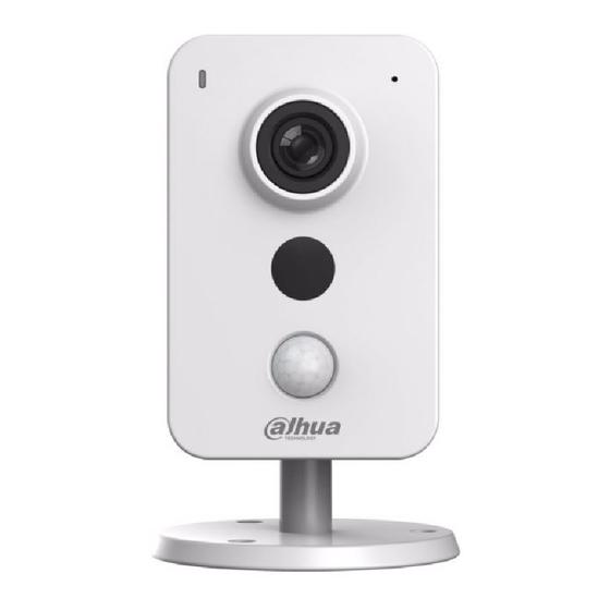
Page 3: Product Appearance
2 Product Appearance Figure 2-1 Figure 2-2 Figure 2-3 Please refer to the following sheet for more details about each port. Name Ethernet port (Wireless connection mode is available as well) Reset/WPS (Wi-Fi Protected Setup) button Digital input/output (Refer to chapter 4 for connection mode) Power port Speaker... - Page 4 Micro SD card slot Indicator light Microphone IR LED PIR (Sense IR ray, trigger alarm) Sheet 2-1 Note: For reset, long press for 8 seconds and then the light off; For WPS (Wi-Fi Protected Setup), one quick press. Please refer to the following sheet for more details about status of indicator light. Indicator light status Device status Red light stably on...
- Page 5 3 Operate by Easy4ip APP Step 1 Power on the device with power adapter. Step 2 Connect your smart phone to your Wi-Fi network. Scan the “Easy4ip” QR on the packing box, download and install the Easy4ip APP. Step 3 Open Easy4ip APP (take IOS as an example), tap login to login the APP, see Figure 3-1.
- Page 6 Figure 3-2 Step 5 Scan the QR code on the back of the camera to get the SN, you can also tap “Continue without scanning” and manually input the SN number on the next page.
- Page 7 Figure 3-3 Step 6 Fill in the Username and Password of the new camera, both of which are admin by default.
- Page 8 Figure 3-4 Step 7 Select “Yes, config Wi-Fi”, and fill in your Wi-Fi password, then tap “Next”. During the Wi-Fi connecting process, please put your smartphone and the camera within 30cm.
- Page 9 Figure 3-5 Figure 3-6 Step 8 Your Camera will be added to your account.
- Page 10 Figure 3-7 Note: If you have more cameras, please follow steps 4-8 to add them one by one. If you want to change the Wi-Fi signal, please reset the camera to factory default and repeat steps 4-8 to add the device.
- Page 11 4 External Alarm Input/Output Device IPC supports external alarm device, it can externally connect to alarm input/output device via “Digital input/output”. 4.1.1 Alarm Input Device (detector, sensor and so on) Please refer to the following figure for alarm input information. See Figure 4-1. Alarm input: When the input signal is idle or grounded, the device can collect the different statuses of the alarm input port.
- Page 12 Mode A: Level application. Alarm output high and low level, alarm output is OC; it needs to increase pull-up resistance externally to work normally. Max external pull-up level is 5V, max port current is 5mA. After external pull-up resistance is increased, the default of output signal is high level (external pull-up voltage), and it switches to low level when there is alarm output (when the working current is 5mA, output voltage is less than 0.8V).
-
Page 13: Device Installation
5 Device Installation Important: Please make sure the installation surface can min support the 3X weight of the camera and the bracket. Figure 5-1 Step 1 Paste the installation map on the installation surface such as wall, ceiling or the wood. Step 2 Dig holes in the installation surface according to the installation map. - Page 14 Note: This quick start guide is for reference only. Slight difference may be found in user interface. All the designs and software here are subject to change without prior written notice. All trademarks and registered trademarks mentioned are the properties of their respective owners.
Need help?
Do you have a question about the K Series and is the answer not in the manual?
Questions and answers