
Related Manuals for Keysight Technologies E5260 Series


Summary of Contents for Keysight Technologies E5260 Series
- Page 1 Keysight Technologies E5260/E5270 Series of Parametric Measurement Solutions User’s Guide...
- Page 2 Notices Copyright Notice U.S. Government Rights Warranty © Keysight Technologies 2004-2015 The Software is “commercial computer soft- THE MATERIAL CONTAINED IN THIS DOCU- ware,” as defined by Federal Acquisition Reg- MENT IS PROVIDED “AS IS,” AND IS SUBJECT No part of this manual may be reproduced in ulation (“FAR”) 2.101.
- Page 3 COMPLIANCE WITH GERMAN NOISE REQUIREMENTS This is to declare that this product is in conformance with the German Regulation on Noise Declaration for Machines (Lärmangabe nach der Maschinenlärminformation-Verordnung -3.GSGV Deutschland). • Herstellerbescheinigung GERÄUSCHEMISSION Lpa < 70 dB am Arbeitsplatz normaler Betrieb nach DIN 45635 T.
- Page 4 In addition, it violates safety standards of design, manufacture, and intended use of the instrument. Keysight Technologies assumes no liability for customer’s failure to comply with these requirements.
- Page 5 Instruments that appear damaged or defective should be made inoperative and secured against unintended operation until they can be repaired by qualified service personnel. Return the instrument to a Keysight Technologies sales or service office for services and repair to ensure that safety features are maintained.
- Page 6 Safety Symbols The general definitions of safety symbols used on equipment or in manuals are listed below. Direct current. Alternating current. Earth ground terminal. Protective conductor terminal. For protection against electrical shock in case of a fault. Used with field wiring terminals to indicate the terminal which must be connected to ground before operating equipment.
- Page 7 The CSA mark is a registered trademark of the Canadian Standards Association. The RCM mark is a registered trademark of the Australian Communications Authority. This signifies compliance with the Australian EMC Framework Regulations under the terms of the Radio communications Act. This ISM device complies with Canadian ICES-001.
- Page 8 Power Supply and Measurement Safety • Power Supply Safety This instrument can output high currents and voltages. Make sure that the load or device under test can safely handle the output current and voltage. Also, make sure that the connection leads can safely withstand the expected currents and are insulated for the expected voltages.
- Page 9 • Source/Monitor Terminals Source/monitor unit, SMU, can simultaneously perform DC voltage or current output and measurement. Typical SMU has the Force, Guard, Sense, and Circuit Common terminals as shown below. Normally the Force, Guard, and Sense terminals are the same potential. Voltage marked around the terminals indicates the Protection Limits. Force and Sense must be connected to a terminal of a device under test for the Kelvin connection which is effective for high current measurement and low resistance measurement.
- Page 10 High Voltage Shock Hazard Keysight E5260/E5270 can force dangerous voltages (±200 V for HPSMU and ±100 V for MPSMU/HRSMU) at the Force, Guard, and Sense terminals. To prevent electric shock hazard, the following safety precautions must be observed during the use of Keysight E5260/E5270.
- Page 11 Gefahr durch Hochspannung Von den Geräten Keysight E5260/E5270 können Spannungen an den Anschlüssen “Force”, “Guard” und “Sense” von bis zu 200 V ausgehen. Um elektrischem Schlag vorzubeugen, ist bei der Benützung der Geräte Keysight E5260/E5270 folgendes zu beachten. • Verwenden Sie ein dreiphasiges AC-Stromkabel für die Gerätsteckvorrichtung (Eingang) und schließen Sie das Instrument an eine Erdung an (Sicherheitserdung).
- Page 12 Danger de choc dû à une haute tension Une tension dangereuse (max. ± pour HPSMU; 200 Vdc, max. ± pour MPSMU/ HRSMU; 100 Vdc) émanant du dispositif Keysight E5260/E5270 peut être sortie aux bornes Force, Guard et Sense. Les précautions suivantes doivent être obserées contre commotion élec- trique accidentelle.
- Page 13 高電圧感電注意 Keysight E5260/E5270 の Force、Guard、Sense 端子には、危険電圧が出力されることが あります(HPSMU の場合は最大 ±200 Vdc、MPSMU/HRSMU の場合は最大 ±100 Vdc) 。 感電事故防止のため、必ず以下の事柄を守ってください。 • 3 極電源ケーブルを使用して本器を接地してください。 • ドアを開くことによって開放されるインターロック回路を装備し、被測定デバ イスとのインタフェースを覆うことのできるシールド・ボックスを用意してく ださい。 • 測定を開始する前にはインターロック回路を本器の Interlock 端子に接続してく ださい。 • インターロック機能が正常であることを定期的に確認してください。 • Force、Guard、Sense 端子に繋がる接続部に触れる前には、本器の電源を切断し てください。また、測定系のキャパシタを放電してください。電源を切らない 場合は、以下の事項を全て実施してください。 • OutCh、On/Off キーを押して Output インジケータが消灯したことを確認して ください。 •...
- Page 14 Product Stewardship • Waste Electrical and Electronic Equipment (WEEE) The crossed out wheeled bin symbol indicates that separate collection for waste electric and electronic equipment (WEEE) is required, as obligated by the EU DIRECTIVE and other National legislation. Please refer to http://keysight.com/go/takeback to understand your Trade in options with Keysight in addition to product takeback instructions.
- Page 15 In This Manual This manual describes the front panel operation, installation, and functions of the Keysight Technologies E5270B/E5260A/E5262A/E5263A (Keysight E5260/E5270 series). This manual consists of the following chapters: "Getting Started" This chapter briefly explains how to use the Keysight E5260/E5270 by the front panel operation.
-
Page 17: Table Of Contents
Contents 1. Getting Started 2. Introduction Keysight E5260/E5270 Series........2-3 Front View . - Page 18 Contents Installing Accessories ......... 3-13 To Connect 16442B Test Fixture .
- Page 19 Contents Setup Menus ..........4-18 Setup Menu .
- Page 20 Contents To Use Series Resistor ........5-19 To Use Filter .
- Page 21 Contents Measurement Time ..........6-16 Integration Time.
- Page 22 Contents Self-test/Calibration Error ........7-20 Keysight E5260/E5270 User’s Guide, Edition 6...
-
Page 23: Getting Started
Getting Started... - Page 24 Getting Started This chapter describes the basic operations of the Keysight E5260/E5270. Before learning details of the Keysight E5260/E5270, let’s try to use the Keysight E5260/E5270 briefly. The operations need the Keysight E5260/E5270 and power cable only. During the operations, open the measurement terminals. Basic Operations: “Turning on the Keysight E5260/E5270”...
- Page 25 Getting Started Keysight E5260/E5270 Front Panel: HIGH VOLTAGE Measure Output Edit E5270B Reset Local Meas Meas Exit Shift Range Range Stat Meas Value #1 Meas Value #2 Setting Parameter Shift 1.23456mA 1.23456mV OUT: 1.234mV Cal/Test SerRes Circuit Zero GNDU Menu Meas Single Fast...
- Page 26 Getting Started Step 1. Turning on the Keysight E5260/E5270 Connect the power cable from the Keysight E5260/E5270 to an AC power outlet, and press the switch. Line After the self-calibration, the LCD shows the following display: Stat Meas Value #1 Meas Value #2 Setting Parameter Shift...
- Page 27 Getting Started Step 3. Setting up SMU2, forcing DC voltage, and measuring DC current 1. Press the key until the S-ch status area displays 2. The SMU2 setup OutCh information is displayed in the Setting Parameter area. 2. Press the key until the M-ch status area displays 2.
- Page 28 Getting Started Step 5. Executing a spot measurement, and starting repeat measurement 1. Press the key to execute the spot measurement. Single 2. Press the key to start the repeat measurement again. Repeat The LCD changes the display as shown below. The following data is just an example.
- Page 29 Getting Started Step 7. Changing measurement item during repeat measurement 1. Press the key. The voltage measurement data is also displayed as MeasItem shown below. The following data is just an example. Stat Meas Value # 1 Meas Value # 2 Setting Parameter Shift 0.00015nA...
- Page 30 Getting Started Step 8. Stopping source output and measurement 1. Press the key. The SMU2 stops source output and measurement. On/Off Stat Meas Value # 1 Meas Value # 2 Setting Parameter Shift OUT: 1.500 V CPL: 100.0mA Lock Meas Trigger Error Integ R epeat R em ote Output...
-
Page 31: Introduction
Introduction... - Page 32 Introduction This chapter describes the basic functions and features of the Keysight E5270B/ E5260A/E5262A/E5263A (Keysight E5260/E5270 series), and consists of the following sections: • “Keysight E5260/E5270 Series” • “Front View” • “Rear View” • “Measurement Modules” • “Accessories and Options” Keysight E5260/E5270 User’s Guide, Edition 6...
-
Page 33: Keysight E5260/E5270 Series
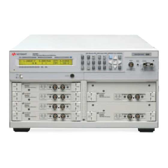
Introduction Keysight E5260/E5270 Series Keysight E5260/E5270 Series The Keysight E5260/E5270 series is an electronic instrument for the semiconductor DC parametric measurement. The Keysight E5260/E5270 provides the LCD and front panel keys for applying/measuring DC voltage or current. The Keysight E5260/E5270 also provides several functions, such as sweep output, pulse output, and trigger functions, in the GPIB remote condition. -
Page 34: Front View
Introduction Front View Front View This section describes the front view of the Keysight E5260/E5270 series. HIGH VOLTAGE Measure Output Edit E5270B Reset Local Meas Meas Exit Shift Range Range Stat Meas Value #1 Meas Value #2 Setting Parameter Shift 1.23456mA 1.23456mV OUT: 1.234mV... - Page 35 Introduction Front View • Zero Check terminal Ground reference point of the instrument. CAUTION The Zero Check terminal can be used for the service purpose only. For the normal operation, leave this terminal open and do not connect anything to this terminal. Connecting anything can damage the instrument.
- Page 36 Introduction Front View • SMU terminals The source/monitor unit (SMU) has two triaxial connectors, force and sense, for the Kelvin connections. When you use the 16442B test fixture and Kelvin connections, up to 3 SMUs can be connected to the 16442B test fixture. The medium power source/monitor unit (MPSMU) and the high resolution source/monitor unit (HRSMU) occupy one slot.
-
Page 37: Rear View
GPIB cable to connect to an external computer or equipment. • LINE input receptacle AC power cable is connected to this receptacle. • Serial number You need this serial number when using the Keysight Technologies telephone assistance program. Keysight E5260/E5270 User’s Guide, Edition 6... -
Page 38: Measurement Modules
Introduction Measurement Modules Measurement Modules The source/monitor unit (SMU) can force a constant voltage or current, and can measure a DC current or voltage. Figure 2-1 is a simplified SMU circuit diagram. The SMU can perform the following operations: • Apply voltage and measures current •... -
Page 39: Gndu - Ground Unit
Introduction Measurement Modules GNDU - Ground Unit The Keysight E5260/E5270 is equipped with the ground unit (GNDU). The GNDU is a 0 V constant voltage source, and used for the reference of measurement ground. Also the GNDU can sink up to ± 4 A (E5260A/E5270B) or ± 2.2 A (E5262A/E5263A), so it is effective for using the HPSMU (high power SMU). -
Page 40: E5280B Precision Hpsmu
Introduction Measurement Modules E5280B Precision HPSMU This section describes typical specification of the high power source/monitor unit (HPSMU) for the Keysight E5270B. The E5280B cannot be used with the E5260A. • Maximum voltage, current, output power: ± 200 V, ± 1 A, 20 W •... - Page 41 Introduction Measurement Modules Table 2-1 HPSMU Output Voltage Ranges and Resolutions Setting Maximum Range Output Value Resolution Current 0 ≤ |V| ≤ 2 V 100 μV ± 1000 mA 0 ≤ |V| ≤ 20 V 20 V 1 mV ± 1000 mA 0 ≤...
- Page 42 Introduction Measurement Modules Table 2-3 HPSMU Measurement Voltage Values and Resolutions Measurement Resolutions Measurement Range Value High Speed ADC High Resolution ADC 0 ≤ |V| ≤ 2.2 V 100 μV 2 μV 0 ≤ |V| ≤ 22 V 20 μV 20 V 1 mV 0 ≤...
-
Page 43: E5281B Precision Mpsmu
Introduction Measurement Modules E5281B Precision MPSMU This section describes typical specification of the medium power source/monitor unit (MPSMU) for the Keysight E5270B. The E5281B cannot be used with the E5260A. • Maximum voltage, current, output power: ± 100 V, ± 100 mA, 2 W •... - Page 44 Introduction Measurement Modules Table 2-5 MPSMU Output Voltage Ranges and Resolutions Setting Maximum Range Output Value Resolution Current 0 ≤ |V| ≤ 0.5 V 100 μV 0.5 V ± 100 mA 0 ≤ |V| ≤ 2 V 100 μV ± 100 mA 0 ≤...
- Page 45 Introduction Measurement Modules Table 2-7 MPSMU Measurement Voltage Values and Resolutions Measurement Resolutions Measurement Range Value High Speed ADC High Resolution ADC 0 ≤ |V| ≤ 0.55 V 25 μV 0.5 μV 0.5 V 0 ≤ |V| ≤ 2.2 V 100 μV 2 μV 0 ≤...
-
Page 46: E5287A Atto Level Hrsmu
Introduction Measurement Modules E5287A Atto Level HRSMU This section describes typical specification of the high resolution source/monitor unit (HRSMU) for the Keysight E5270B. The E5287A and the E5288A Atto Sense and Switch Unit (ASU) cannot be used with the E5260A. •... - Page 47 Introduction Measurement Modules Table 2-9 HRSMU Output Voltage Ranges and Resolutions Setting Maximum Range Output Value Resolution Current 0 ≤ |V| ≤ 0.5 V 100 μV 0.5 V ± 100 mA 0 ≤ |V| ≤ 2 V 100 μV ± 100 mA 0 ≤...
- Page 48 Introduction Measurement Modules Table 2-11 HRSMU Measurement Voltage Values and Resolutions Measurement Resolutions Measurement Range Value High Speed ADC High Resolution ADC 0 ≤ |V| ≤ 0.55 V 25 μV 0.5 μV 0.5 V 0 ≤ |V| ≤ 2.2 V 100 μV 2 μV 0 ≤...
- Page 49 Introduction Measurement Modules NOTE To connect ASU To use the ASU, it must be connected to the SMU which is connected together when the calibration is performed. The specifications are satisfied and guaranteed in this condition only. So confirm the serial number of the ASU and connect it to the dedicated SMU properly.
-
Page 50: E5290A High Speed Hpsmu
Introduction Measurement Modules E5290A High Speed HPSMU This section describes typical specification of the high power source/monitor unit (HPSMU) for the Keysight E5260A. The E5290A cannot be used with the E5270B. • Maximum voltage, current, output power: ± 200 V, ± 1 A, 20 W •... - Page 51 Introduction Measurement Modules Table 2-13 HPSMU Output Voltage Ranges and Resolutions Setting Maximum Range Output Value Resolution Current 0 ≤ |V| ≤ 2 V ± 1000 mA 1 mV 0 ≤ |V| ≤ 20 V 20 V 1 mV ± 1000 mA 0 ≤...
- Page 52 Introduction Measurement Modules Table 2-15 HPSMU Measurement Voltage Values and Resolutions Range Measurement Resolutions Measurement Value 0 ≤ |V| ≤ 2.2 V 100 μV 0 ≤ |V| ≤ 22 V 20 V 1 mV 0 ≤ |V| ≤ 44 V 40 V 2 mV 0 ≤...
-
Page 53: E5291A High Speed Mpsmu
Introduction Measurement Modules E5291A High Speed MPSMU This section describes typical specification of the medium power source/monitor unit (MPSMU) for the Keysight E5260A. The E5291A cannot be used with the E5270B. • Maximum voltage, current, output power: ± 100 V, ± 200 mA, 4 W •... - Page 54 Introduction Measurement Modules Table 2-17 MPSMU Output Voltage Ranges and Resolutions Setting Maximum Range Output Value Resolution Current 0 ≤ |V| ≤ 2 V ± 200 mA 1 mV 0 ≤ |V| ≤ 20 V 20 V 1 mV ± 200 mA 0 ≤...
- Page 55 Introduction Measurement Modules Table 2-19 MPSMU Measurement Voltage Values and Resolutions Range Measurement Resolutions Measurement Value 0 ≤ |V| ≤ 2.2 V 100 μV 0 ≤ |V| ≤ 22 V 20 V 1 mV 0 ≤ |V| ≤ 44 V 40 V 2 mV 0 ≤...
-
Page 56: Accessories And Options
Introduction Accessories and Options Accessories and Options The Keysight E5260/E5270 is furnished with the following accessories. • Power Cable, 1 ea. • Operation Summary Sheet, 1 ea. • Software CD, 1ea. Table 2-21 lists the options and the available accessories for the Keysight E5260/E5270. - Page 57 Introduction Accessories and Options Table 2-21 Options and Accessories Model Option Item Description Number E5260A 8 Slot High Speed Measurement Mainframe E5260A-050 50 Hz power line frequency E5260A-060 60 Hz power line frequency E5260A-A6J ANSI Z540 compliant calibration E5260A-UK6 Commercial cal. certificate w/ test data E5260A-ABA Manual set, English E5260A-ABJ...
- Page 58 Introduction Accessories and Options Model Option Item Description Number E5270B 8 Slot Precision Measurement Mainframe E5270B-050 50 Hz power line frequency E5270B-060 60 Hz power line frequency E5270B-A6J ANSI Z540 compliant calibration E5270B-UK6 Commercial cal. certificate w/ test data E5270B-ABA Manual set, English E5270B-ABJ Manual set, Japanese...
- Page 59 Introduction Accessories and Options Model Option Item Description Number 16442B Test Fixture 16442B-010 Add 1.5 m triaxial cables, 4 ea. 16442B-011 Add 3.0 m triaxial cables, 4 ea. 16442B-800 Extra blank PTFE board 16442B-801 Universal socket module, 0.1 inch pitch, with 10 pins 16442B-802 Universal socket module, 0.075 inch pitch, with 10 pins 16442B-803...
- Page 60 Introduction Accessories and Options Model Option Item Description Number 16493M Triaxial and D-sub Cable for ASU 16493M-001 1.5 m length 16493M-002 3.0 m length 16494A Triaxial Cable 16494A-001 1.5 m length 16494A-002 3 m length 16494A-003 80 cm length 16494B Kelvin Triaxial Cable (E5260/E5270 to E5250 input) 16494B-001 1.5 m length...
-
Page 61: Installation
Installation... - Page 62 Installation This chapter describes how to install Keysight E5260/E5270 and accessories. • “Requirements” • “Inspection and Installation” • “Installing Accessories” • “Mounting Connectors” • “Connecting Measurement Devices” • “Maintenance” WARNING To avoid electrical shock and instrument damage, turn the all instruments off before connecting or disconnecting measurement cable.
- Page 63 Installation • Confirm that the HIGH VOLTAGE indicator is not lit. • Open the Interlock terminal (open the fixture cover or the shielding box access door). • Discharge any capacitors connected to an SMU. • Warn persons working around this instrument about dangerous conditions. WARNING Une tension dangereuse (max.
-
Page 64: Requirements
Installation Requirements Requirements This section contains information on: • “Power Requirements” • “Operating Environment” • “Storaging/Shipping Environment” • “Installation Requirements” • “Power Cable” Power Requirements This instrument can operate from any single-phase AC power source supplying 100-240 V (±10 %) at 50/60 Hz. The maximum power consumption is 600 VA for the Keysight E5260A/E5270B, and 400 VA for the Keysight E5262A/E5263A. -
Page 65: Installation Requirements
Installation Requirements Installation Requirements WARNING Do not operate the instrument in dusty environment, or in the presence of flammable gasses, corrosive gasses, or fumes. Ne pas utiliser l’appareil dans un endroit poussiéreux, ou en présence de gaz inflammables, corrosifs ou de fumée. •... - Page 66 Installation Requirements Option 900 Option 901 Option 902 Option 903 • Plug: NEMA 5-15P, • Plug: IEC 60277-1, • Plug: AS/NZS 3112, • Plug: BS 1363/A, 125 V, 10 A 250 V, 10 A 250 V, 10 A 250 V, 10 A •...
- Page 67 Installation Requirements NOTE The detachable power cable may be used as an emergency disconnecting device. Removing the power cable will disconnect AC input power to the instrument. Connect the power cable to the IEC 60320 connector on the rear of the instrument. If the wrong power cable was shipped with your instrument, contact your nearest Keysight Sales and Support Office.
-
Page 68: Inspection And Installation
• water marks If you suspect any damage, notify your local Keysight Technologies sales or service office. 2. When you open the boxes that contain the instrument and accessories, check the components against the contents lists attached to the boxes. -
Page 69: To Execute Diagnostics And Self-Calibration
Installation Inspection and Installation WARNING If the Circuit Common terminal is not connected to the frame ground terminal (for floating measurement), a potential shock hazard may present. Do not touch any of measurement circuit at any time while a floating measurement is in progress. -
Page 70: To Remove Or Install Plug-In Module
For calibration, you need the dedicated equipment and accessories. Prepare the all required items or contact your nearest Keysight Technologies service center. 3-10 Keysight E5260/E5270 User’s Guide, Edition 6... - Page 71 Installation Inspection and Installation Removal 1. Turn off the mainframe, then wait at least 10 seconds. See Figure 3-2. 2. Disconnect the power cable from rear panel. 3. Disconnect all cables from the modules. 4. Loosen the screws on the plate. 5.
- Page 72 Installation Inspection and Installation Figure 3-2 Plug-in Module Removal and Installation 3-12 Keysight E5260/E5270 User’s Guide, Edition 6...
-
Page 73: Installing Accessories
Installation Installing Accessories Installing Accessories This section describes how to install the Keysight E5260/E5270 and accessories. Additional information regarding airflow can be found in the “Installation Requirements” on page 3-5. This section describes how to: • “To Connect 16442B Test Fixture” •... - Page 74 Installation Installing Accessories WARNING This instrument supports the Interlock function to prevent you from receiving an electrical shock from high voltage (more than ± 42 V). If the Interlock terminal is open, this instrument cannot apply high voltage more than ± 42 V. If you do not use the 16442A/B test fixture, install an interlock circuit (see page 3-26) and connect it to the Interlock terminal.
-
Page 75: To Connect 16442B Test Fixture
Installation Installing Accessories To Connect 16442B Test Fixture See this section if you use the Keysight 16442B Test Fixture. This section describes how to set up the 16442B and how to connect the E5260/E5270 to the 16442B. To Set up 16442B You can stabilize the 16442B as shown in the figure below. - Page 76 Installation Installing Accessories To Connect 16442B Use the following cables to connect from the E5260/E5270 connectors to the 16442B’s relative connectors. 16442B E5260/E5270 Cables Terminals Terminals Keysight 16493J Interlock Cable, 3 m or 1.5 m Intlk Interlock Keysight 16493L GNDU Cable, 3 m or 1.5 m GNDU GNDU For Kelvin connection:...
-
Page 77: To Connect Connector Plate
Installation Installing Accessories To Connect Connector Plate The connector plates available are listed in Table 3-1. Option 001 provides the through connectors except for the Interlock connector that provides the soldering patterns at the back side. For the option 002, the back of each connector is designed for soldering. - Page 78 Installation Installing Accessories Table 3-2 To Connect Connector Plate Connector E5260/E5270 Cables Plate Terminals Keysight 16493J Interlock Cable, 3 m or 1.5 m Intlk Interlock Keysight 16493L GNDU Cable, 3 m or 1.5 m GNDU GNDU For Kelvin connection: Force Keysight 16493K Kelvin Triaxial Cable, 3 m Sense or 1.5 m...
-
Page 79: To Connect Asu
Installation Installing Accessories To Connect ASU Keysight E5288A Atto Sense and Switch Unit (ASU) adds the following functions to the high resolution SMU (HRSMU). To use the ASU, it must be connected to the HRSMU which is connected together when the calibration is performed. •... - Page 80 Installation Installing Accessories To install 16495K Fix the 16495K plate to the shielding box or something that will cover the DUT interface. See Keysight 16495 Installation Guide. The 16495K is the plate that has the mechanism to block the light from the cable hole used to pass the cables in the shielding box.
- Page 81 Installation Installing Accessories To connect 4284A/ Perform the following procedure to connect the Keysight 4284A/E4980A. See E4980A to AUX Figure 3-4 Figure 3-5. Prepare a shorting bar furnished with the ASU. The shorting bar is effective for reducing the offset capacitance caused by connecting a measurement terminal to the chuck of a wafer prober.
- Page 82 Installation Installing Accessories Figure 3-4 To Connect ASU ASU #1 CMU-cur/AUX In To CMU CMU-pot Force/CMU/AUX To DUT Force Force Sense To SMU From SMU D-sub CMU Return/AUX Common ASU #2 CMU Return/AUX Common CMU-cur/AUX In To CMU CMU-pot Force/CMU/AUX To DUT Force Force...
-
Page 83: To Connect Gndu Adapter
Installation Installing Accessories To Connect GNDU Adapter The ground unit (GNDU) output is the single triaxial connector. To change it to the dual triaxial connector, use Keysight N1254A-100 GNDU to Kelvin Adapter. Attach the adapter directly to the front panel as shown below. 1. -
Page 84: Mounting Connectors
Installation Mounting Connectors Mounting Connectors Previous sections described how to install the available accessories, and Keysight 16495 Installation Guide provides the information on how to install connector plates on the shielding box. However, you may choose to mount connectors directly on your own connector plate or test fixture. - Page 85 Installation Mounting Connectors Table 3-3 Recommended Parts Usage Keysight Part No. Description Making an interlock 1252-1419 Interlock Connector (6 pin, female) circuit N1254A-402 Switch ≅ 2.1 V @ I 1450-0641 LED (V = 10 mA) Wire (24 AWG, 600 V, 150 °C) 8150-5680 Connecting GNDU 1250-2457...
-
Page 86: To Make An Interlock Circuit
Installation Mounting Connectors To Make an Interlock Circuit The interlock circuit is designed to prevent electrical shock when a user touches the measurement terminals. CAUTION You must install an interlock circuit on a shielding box to prevent hazardous voltages when the door of the shielding box is open. Figure 3-8 shows the pin assignments of the interlock connector that should be mounted on a connector plate or test fixture. - Page 87 Installation Mounting Connectors Installing the interlock circuit Install the interlock circuit as follows: 1. Mount two mechanical switches on your shielding box, so that the switches close when the door of the shielding box is closed, and open when the door is opened.
- Page 88 Installation Mounting Connectors Figure 3-10 Dimensions of the Interlock Switch (Keysight N1254A-402) 10.3 4.75 35.6 Switch off 15.3 10.3 15.9 18.8 C OM 22.2 27.8 Units: mm 3-28 Keysight E5260/E5270 User’s Guide, Edition 6...
-
Page 89: To Connect The Gndu Output
Installation Mounting Connectors To Connect the GNDU Output The following figures show connection examples for the GNDU output. Kelvin connections non-Kelvin connections Use a low-noise coaxial cable (Keysight part Short the Sense and Force on the connector as number 8121-1189) from the connector to the shown below. -
Page 90: To Connect The Smu Output
Installation Mounting Connectors To Connect the SMU Output The following figures show connection examples for the SMU output. Kelvin connections non-Kelvin connections Use low-noise coaxial cable (Keysight part The following figure is for the connection using number 8121-1191) from the connector to the Kelvin triaxial cable. - Page 91 Installation Mounting Connectors WARNING There are potentially hazardous voltages (± 200 V for HPSMU, and ± 100 V for MPSMU) present at the Force, Guard, and Sense terminals. To prevent electrical shock, do not expose these lines. Before turning the instrument on, connect the Interlock terminal to an interlock circuit.
- Page 92 Installation Mounting Connectors NOTE Low-Noise Coaxial Cable For the extended measurement paths over the connector plate, use low-noise coaxial cable (Keysight part number 8121-1191). This cable can maximize the guard effects and minimize the impression of the external noise. Following figure shows the cutting example of this cable. Key point is the isolation between the conductive layer and the center conductor.
- Page 93 Installation Mounting Connectors Figure 3-11 ASU Output Kelvin Connection Guard Wire Coaxial cable or Force to DUT 1 or Common DUT 1 high terminal Sense CMU Return Guard CMU Return or Force to DUT 2 or Common DUT 1 low terminal Sense Guard The ASU inputs can be connected to the instruments by using a control cable, a...
- Page 94 Installation Mounting Connectors Figure 3-12 ASU Output non-Kelvin Connection Guard Wire or Force Coaxial cable Wire Common to DUT 1 or DUT 1 high terminal Sense CMU Return to DUT 2 or Guard DUT 1 low terminal CMU Return or Force Common Sense Guard...
-
Page 95: Connecting Measurement Devices
Installation Connecting Measurement Devices Connecting Measurement Devices This section describes how to connect device under test (DUT) to the 16442B test fixture, and how to connect cables to the connector plate. If you use a wafer prober, see wafer prober manuals. Note that you must set the module output off when connecting or disconnecting DUTs. -
Page 96: Using Test Fixture
Installation Connecting Measurement Devices Using Test Fixture 1. Press the keys to set the output off. OutCh On/Off 2. Select a proper socket module for your DUT, then set the socket module on the test fixture. 3. Mount your DUT on the socket module. 4. - Page 97 Installation Connecting Measurement Devices WARNING To prevent electrical shock and DUT damage, do not connect or disconnect the DUT while the instrument is applying voltage or current. When you touch the DUT after measurement, devise a countermeasure of residual charge and heat to prevent electrical shock and burn. Use glove and any tool.
-
Page 98: Using Connector Plate
Installation Connecting Measurement Devices Using Connector Plate This section provides the information useful for connecting cables and probing needles to a connector plate. • “To Reduce Leakage Current” • “To Measure Low Resistance” To Reduce Leakage Current To reduce the leakage current caused by connection cables, the guard technique is effective. - Page 99 Installation Connecting Measurement Devices WARNING For safety, prepare and attach a shield cover to the connector plate to avoid touching the joints on the wiring side of connectors. And ground the cover. Wrap an insulator around the naked conductors of coaxial cable to avoid touching it.
- Page 100 Installation Connecting Measurement Devices Guarding Guarding reduces the leakage current between the measurement points and instrument. This is important when you measure low current. The following figure shows the theory of guarding. The buffer amplifier (×1) keeps the potential of the guard conductor at the same potential as the force conductor, so current does not flow between the force and guard conductors.
- Page 101 Installation Connecting Measurement Devices Example The following example connection can be used to measure low resistance. The sense line is extended to the probing pad, and contacts the force line through the pad, so the voltage drop due to the residual resistance caused by cables and test leads is canceled.
- Page 102 Installation Connecting Measurement Devices Lorsque vous touchez le MST après la mesure, élaborez une contre-mesure de la charge résiduelle et du chauffage afin d'éviter tout choc électrique et toute brûlure. Utilisez des gants et des outils. Prévoyez également du temps pour la décharge et la radiation.
-
Page 103: Maintenance
NOTE When shipping the Keysight E5260/E5270 to the service center When you ship the Keysight E5260/E5270 to the Keysight Technologies service center, do not remove the source/monitor unit (SMU) from the mainframe, and ship the mainframe with all SMU modules. -
Page 104: Self-Test And Diagnostics
Installation Maintenance Self-test and Diagnostics Keysight E5260/E5270 provides the following functions to check the operation. Perform the following functions as necessary. • Self-test Refer to “To Perform Self-test” on page 5-7. • Self-calibration Refer to “To Perform Self-Calibration” on page 5-8. -
Page 105: Front Panel Reference
Front Panel Reference... - Page 106 Front Panel Reference This chapter provides the reference information of the Keysight E5260/E5270 front panel keys and display. • “Display and Front Panel Keys” • “Front Panel Key Details” • “Setup Menus” Keysight E5260/E5270 User’s Guide, Edition 6...
-
Page 107: Display And Front Panel Keys
Front Panel Reference Display and Front Panel Keys Display and Front Panel Keys The Keysight E5260/E5270 provides an LCD and 24 front panel keys for front panel operation. This section explains the user interface. • “Display Images” • “Front Panel Key Locations” •... - Page 108 Front Panel Reference Display and Front Panel Keys The display area consists of the following sub areas that have the meanings described below. • In normal operation, or when changing source output or compliance value: Meas Data 1 Meas Data 2 Setup Data 1 Status Data Setup Data 2...
-
Page 109: Front Panel Key Locations
Front Panel Reference Display and Front Panel Keys Front Panel Key Locations The following 24 front panel keys are available. key sets the Keysight E5260/E5270 to the local condition. Local key displays a setup menu. See “Setup Menu” on page 4-18. -
Page 110: Channel Status Area
Front Panel Reference Display and Front Panel Keys Channel Status Area This area displays one of the following status codes that indicate the status of the measurement channels. If some status errors are detected, the most serious status code is displayed in this area. Table 4-1 Channel Status Code Level of... -
Page 111: Setup Data Area
Front Panel Reference Display and Front Panel Keys Setup Data Area The Setup Data 1 and Setup Data 2 areas display the source output setting, the source compliance setting, the measurement range setting, or the error code. The display item can be selected by the MON_ITEM menu, displayed by pressing the key. -
Page 112: Measurement Data Area
Front Panel Reference Display and Front Panel Keys Measurement Data Area The Meas Data 1 and Meas Data 2 areas can display the following items. The display item can be selected by pressing the key. Table 4-3 shows the MeasItem display format in the measurement data area. -
Page 113: Status Data Area
Front Panel Reference Display and Front Panel Keys Status Data Area Remote Meas Error Integ Output Repeat M- ch S- ch Lock Trigger The Status data area shows the following statuses. Label Description Remote Remote status indicator. The triangle mark appears when the Keysight E5260/E5270 is in the remote condition. -
Page 114: Front Panel Key Details
Front Panel Reference Front Panel Key Details Front Panel Key Details The front panel keys are used to change the instrument settings, apply DC bias, measure DC current or voltage, and so on. When the Change Setup area is displayed, only the Edit keys except for the Shift are available. -
Page 115: Measure Key Group
Meas Data area. The measurement item can be specified for each measurement channel. The Keysight E5260 series does not have this shift key. Available only for the (Shift+MeasItem) Keysight E5270B. This shift key operation displays the following message. - Page 116 Front Panel Reference Front Panel Key Details Integ Selects the A/D converter (ADC) operation mode (A: auto, M: manual, or P: PLC). Refer to Table 4-4. For the Keysight E5260, see the description of the H-SPEED. Press the key to specify the measurement channel, and press the MeasCh Integ repeatedly until the desired mode appears in the Integ status area.
- Page 117 Front Panel Reference Front Panel Key Details Table 4-4 AD, Integ, and IntegTime Values Integ IntegTime message and description H-SPEED [M-ch #] H-SPEED A N*Ref[pt], N= Specify the N value shown in the following formula. Available values are 1 to 1023. Initial value is 1. Number of averaging samples = N ×...
-
Page 118: Output Key Group
Front Panel Reference Front Panel Key Details Output key group The Output key group is used to set up the source condition and apply the source output. OutCh Selects the source channel effective for the data displayed in the Setup Data area. Press the key repeatedly until the desired channel number appears in the S-ch OutCh... - Page 119 Front Panel Reference Front Panel Key Details AUX On/Off The Keysight E5260 series does not have this function. This function is available for (Shift+CPL Value) the Keysight E5270B installed with the high resolution SMU (HRSMU). To use the ASU (Atto Sense and Switch Unit), connect the ASU to the HRSMU properly.
- Page 120 Front Panel Reference Front Panel Key Details Switches the source output mode, voltage output or current output. Pressing the key changes the output mode immediately. It also changes the measurement item as shown below: Source Output Mode Meas Data 1 Meas Data 2 V (voltage output) Voltage...
-
Page 121: Edit Key Group
Front Panel Reference Front Panel Key Details Edit key group The Edit key group is used to move the cursor in the display area, make the setup value effective, return to the previous menu or display, and so on. Shift Enables the sub key function. -
Page 122: Setup Menus
Front Panel Reference Setup Menus Setup Menus This section explains the following setup menus displayed in the Change Setup area. • “Setup Menu” • “Calibration and Test Menu” • “Measurement Range Setup Menu” • “Output Range Setup Menu” Setup Menu Press the key. - Page 123 Front Panel Reference Setup Menus Function Tree The setup menu provides the following functions. • CONFIG • Sets the GPIB address. ADDRESS • LINEFREQ Sets the power line frequency. • REVISION Displays the firmware revision. • Displays the module information of each slot. UNIT •...
- Page 124 Front Panel Reference Setup Menus CONFIG Displays the sub menu that provides the following functions. • ADDRESS Displays the following message. GPIB Address = Address Press the arrow key to set the desired GPIB address. Then, press the key to Enter make the setup effective, or press the key to cancel changing the setup.
- Page 125 Front Panel Reference Setup Menus • SERIAL Displays the following message. Slot#: xxxxxxxxxx where # is 1 or 2 for the 2-ch mainframe, 1, 2, ... or 8 for the 8-ch mainframe, xxxxxxxxxx is the serial number of the module installed in the slot #. If the atto sense and switch unit (ASU) is connected to the high resolution SMU (HRSMU), the following message will be displayed.
- Page 126 Front Panel Reference Setup Menus MON_ITEM Displays the sub menu that provides the following functions. • Selects the item displayed in the Setup Data 1 area. ITEM1 • Selects the item displayed in the Setup Data 2 area. ITEM2 Move the cursor to the function you want to set, and press the key.
- Page 127 Front Panel Reference Setup Menus WAIT_TIME Displays the sub menu that provides the following functions. • Sets the source wait time. SOURCE • Sets the measurement wait time. MEASURE Move the cursor to the function you want to set, and press the key.
- Page 128 Front Panel Reference Setup Menus ERROR Displays the sub menu that provides the following functions. • DISPLAY Displays the error code and error message, or No Error. A maximum of four error messages can be stored. To return to the previous menu, press the key.
-
Page 129: Calibration And Test Menu
Front Panel Reference Setup Menus Calibration and Test Menu Press the key and the key. The calibration and test menu is displayed in Shift Menu the Change Setup area as shown below. The menu is used to set the auto-calibration, to execute the self-calibration, self-test, and diagnostics, and so on. - Page 130 Front Panel Reference Setup Menus AUTO_CAL Displays the following message. Auto Calibration: ON or OFF Press the arrow key to set auto-calibration ON or OFF. Then, press the key to Enter make the setup effective, or press the key to cancel changing the setup. Exit The auto-calibration function automatically starts calibration for all modules every 30 minutes if the output switches of all modules are off for 30 minutes.
- Page 131 Front Panel Reference Setup Menus Displays the sub menu that provides the following functions. • EXECUTE Displays the following message. Calibration: ALL Press the arrow key to select the slot to calibrate. Then, press the key to Enter start self-calibration, or press the key to return to the previous menu without Exit performing self-calibration.
- Page 132 Front Panel Reference Setup Menus SELFTEST Displays the sub menu that provides the following functions. • EXECUTE Displays the following message. Selftest: ALL Press the arrow key to select the test item. Then, press the key to start the Enter self-test, or press the key to return to the previous menu without performing Exit...
- Page 133 Front Panel Reference Setup Menus DIAG Displays the sub menu that provides the following functions. • EXECUTE Displays the following message. DIAG: Item where Item is one of the following: • GPIB GPIB diagnostics • TRIGGER (BNC) Trigger In/Out diagnostics •...
- Page 134 Front Panel Reference Setup Menus Table 4-5 To Perform Diagnostics Item Description GPIB For the next message, disconnect the GPIB cable from the GPIB connector. Then, press key to start diagnostics or the key to return to the previous menu. Enter Exit Open GPIB, then press [Enter].
-
Page 135: Measurement Range Setup Menu
Front Panel Reference Setup Menus Measurement Range Setup Menu Press the key to display the measurement range setup menu. The MeasRange measurement range setup menu is displayed in the Change Setup area as shown below. The menu is used to set the voltage measurement ranging mode (V_RANGE) or the current measurement ranging mode (I_RANGE). -
Page 136: Output Range Setup Menu
Front Panel Reference Setup Menus Output Range Setup Menu Press the key to display the output range setup menu. The output range OutRange setup menu is displayed in the Change Setup area as shown below. The menu is used to set the voltage output ranging mode (V_RANGE) or the current output ranging mode (I_RANGE). -
Page 137: Front Panel Operations
Front Panel Operations... - Page 138 Front Panel Operations This chapter explains how to use the Keysight E5260/E5270 in the local mode. • “Available Functions” • “Setting Up Keysight E5260/E5270” • “Applying Source Output” • “Making Measurement” NOTE Local Key Front panel operation is available when the Keysight E5260/E5270 is being set to local mode.
-
Page 139: Available Functions
Front Panel Operations Available Functions Available Functions Table 5-1 lists the typical functions of the Keysight E5260/E5270. Table 5-1 Typical Functions Operating Condition/Mode Function Local Remote To use multiple source channels Available Available To use multiple measurement channels Not available Available To apply DC voltage or DC current Available... -
Page 140: Setting Up Keysight E5260/E5270
Front Panel Operations Setting Up Keysight E5260/E5270 Setting Up Keysight E5260/E5270 This section describes the following tasks of setting up the Keysight E5260/E5270. • “To Set Line Frequency” • “To Initialize Keysight E5260/E5270” • “To Set Beeper” • “To Apply Default Value” •... -
Page 141: To Set Line Frequency
Front Panel Operations Setting Up Keysight E5260/E5270 To Set Line Frequency 1. Press the key. Menu 2. Move the cursor to CONFIG, then press the key. Enter 3. Move the cursor to LINEFREQ, then press the key. Enter 4. Press the arrow keys to select the line frequency 50 Hz or 60 Hz. 5. -
Page 142: To Select Monitor Items
Front Panel Operations Setting Up Keysight E5260/E5270 To Select Monitor Items The following procedure selects the items displayed in the Setup Data area. 1. Press the key. Menu 2. Move the cursor to MON_ITEM, then press the key. Enter 3. Move the cursor to ITEM1 for the Setup Data 1 area, then press the key. -
Page 143: To Perform Self-Test
Front Panel Operations Setting Up Keysight E5260/E5270 To Perform Self-test 1. Open the measurement terminals of the Keysight E5260/E5270. 2. Press the key and the key. Shift Menu 3. Move the cursor to SELFTEST, then press the key. Enter 4. Move the cursor to EXECUTE, then press the key. -
Page 144: To Perform Self-Calibration
Front Panel Operations Setting Up Keysight E5260/E5270 To Perform Self-Calibration 1. Open the measurement terminals of the Keysight E5260/E5270. 2. Press the key and the key. Shift Menu 3. Move the cursor to CAL, then press the key. Enter 4. Move the cursor to EXECUTE, then press the key. -
Page 145: To Perform Diagnostics
Front Panel Operations Setting Up Keysight E5260/E5270 To Perform Diagnostics 1. Press the key and the key. Shift Menu 2. Move the cursor to DIAG, then press the key. Enter 3. Move the cursor to EXECUTE, then press the key. Enter 4. - Page 146 Front Panel Operations Setting Up Keysight E5260/E5270 To display diagnostics results 1. Press the key and the key. Shift Menu 2. Move the cursor to DIAG, then press the key. Enter 3. Move the cursor to RESULT, then press the key.
-
Page 147: To Set Auto-Calibration
Front Panel Operations Setting Up Keysight E5260/E5270 To Set Auto-Calibration 1. Press the key and the key. Shift Menu 2. Move the cursor to AUTO_CAL, then press the key. Enter 3. Press the arrow keys to select the auto-calibration ON or OFF. 4. -
Page 148: To Read Error Message
Front Panel Operations Setting Up Keysight E5260/E5270 To Read Error Message 1. Press the key. Menu 2. Move the cursor to ERROR, then press the key. Enter 3. Move the cursor to DISPLAY, then press the key to display the message. Enter 4. -
Page 149: To Display Module Information
Front Panel Operations Setting Up Keysight E5260/E5270 To Display Module Information 1. Press the key. Menu 2. Move the cursor to CONFIG, then press the key. Enter 3. Move the cursor to UNIT, then press the key. The module information is Enter displayed. -
Page 150: To Set Gpib Address
Front Panel Operations Setting Up Keysight E5260/E5270 To Set GPIB Address 1. Press the key. Menu 2. Move the cursor to CONFIG, then press the key. Enter 3. Move the cursor to ADDRESS, then press the key. Enter 4. Press the arrow keys to set the GPIB address. 5. -
Page 151: Applying Source Output
Front Panel Operations Applying Source Output Applying Source Output This section describes the following tasks to apply DC current or DC voltage. • “To Apply DC Current/Voltage” • “To Set Output/Compliance Value” • “To Set Source Output to Zero” • “To Set Output Range”... -
Page 152: To Apply Dc Current/Voltage
Front Panel Operations Applying Source Output To Apply DC Current/Voltage The following procedure applies a DC bias using a source channel. To use multiple source channels, perform the procedure for all source channels. 1. Press the key repeatedly to specify the source channel. OutCh The channel number must appear in the S-ch status area. -
Page 153: To Set Output/Compliance Value
Front Panel Operations Applying Source Output To Set Output/Compliance Value This instruction sets the source output or compliance value of the specified source channel. 1. Press the key to set the output (OUT) value. OUT Value Or press the key to set the compliance (CPL) value. CPL Value 2. -
Page 154: To Set Source Output To Zero
Front Panel Operations Applying Source Output To Set Source Output to Zero This instruction stores the present source setup of all channels, and changes the output value to 0 V. 1. Press the key. ZeroVolt 2. Press the key for the message 0 V Output:YES to perform this Enter operation, or press the key to cancel operation. -
Page 155: To Use Series Resistor
Front Panel Operations Applying Source Output To Use Series Resistor This instruction connects the series resistor to the specified channel internally. 1. Press the key and the key. Shift On/Off 2. Press the arrow keys, and select ON to connect the series resistor. 3. -
Page 156: To Switch Asu Internal Connection
Applying Source Output To Switch ASU Internal Connection The Keysight E5260 series does not have this function. This function is available for the Keysight E5270B installed with the high resolution SMU (HRSMU). To use the ASU (Atto Sense and Switch Unit), connect the ASU to the HRSMU properly. -
Page 157: Making Measurement
Front Panel Operations Making Measurement Making Measurement This section describes the following tasks to measure DC current or DC voltage. • “To Measure DC Current/Voltage” • “To Abort Measurement” • “To Select Measurement Item” • “To Select Measurement Range” • “To Set A/D Converter”... -
Page 158: To Measure Dc Current/Voltage
Front Panel Operations Making Measurement To Measure DC Current/Voltage The following procedure performs DC current or voltage measurement using the specified measurement and source channel. 1. Press the key repeatedly to specify the source and measurement channel. OutCh The channel number must appear in the S-ch status area. 2. -
Page 159: To Abort Measurement
Front Panel Operations Making Measurement To Abort Measurement This instruction aborts measurement by all measurement channels. 1. Press the key and the key. Shift Repeat 2. Press the key for the message Abort:YES to abort measurement, or Enter press the key to cancel the abort operation. -
Page 160: To Select Measurement Range
Front Panel Operations Making Measurement To Select Measurement Range This procedure sets the measurement range of the specified measurement channel. 1. Press the key. MeasRange 2. For voltage measurement, move the cursor to V_RANGE, then press Enter For current measurement, move the cursor to I_RANGE, then press Enter 3. -
Page 161: To Set A/D Converter
Front Panel Operations Making Measurement To Set A/D Converter The A/D converter (ADC) is set by the procedures below. To select A/D converter This function is not available for the Keysight E5260. Available only for the Keysight E5270B. This procedure selects the ADC type used by the specified measurement channel. - Page 162 Front Panel Operations Making Measurement To set integration time This procedure sets the number of averaging samples of the high-speed A/D converter or the integration time of the high-resolution A/D converter. The meaning of the setting value depends on the ADC type and ADC operation mode settings. The value should be increased for reliable and accurate measurement, or decreased for high speed measurement.
-
Page 163: To Set Wait Time
Front Panel Operations Making Measurement To Set Wait Time This instruction sets the source wait time and the measurement wait time. The wait time settings are effective for all modules. Refer to “WAIT_TIME” on page 4-23. 1. Press the key. Menu 2. -
Page 164: To Set Data Display Format
Front Panel Operations Making Measurement To Set Data Display Format This instruction selects the display format of the measurement data displayed in the Measurement Data area. 1. Press the key. Menu 2. Move the cursor to DSPL_FRMT, then press the key. -
Page 165: Function Details
Function Details... - Page 166 Function Details This chapter explains the following measurement functions of the Keysight E5260/E5270, and the initial settings. • “Measurement Mode” • “Ranging Mode” • “Compliance” • “SMU Pulse” • “Measurement Time” • “Atto Sense and Switch Unit” • “Filter” • “Series Resistor”...
-
Page 167: Measurement Mode
Function Details Measurement Mode Measurement Mode The Keysight E5260/E5270 provides different measurement functions for each operation mode; local and remote. Measurement Mode in Local Condition You can select one from the following measurement items: • Current (when applying voltage) or voltage (when applying current) •... -
Page 168: Measurement Mode In Remote Condition
Function Details Measurement Mode Measurement Mode in Remote Condition You can select one of the following measurement modes: • Spot Measurement Applies voltage or current, then measures voltage or current. A maximum of eight measurement channels can be used. • Staircase Sweep Measurement Applies staircase sweep voltage or current, and measures voltage or current at each sweep step. -
Page 169: Ranging Mode
Function Details Ranging Mode Ranging Mode The Keysight E5260/E5270 provides the following operation modes for the measurement range and the output range. The ranging mode must be set for each channel. • “Auto Ranging” • “Limited Auto Ranging” • “Compliance Range” •... -
Page 170: Auto Ranging
Function Details Ranging Mode Auto Ranging Range changing is performed as below. For measurement The measurement channel automatically searches for and measures at the range that channels provides the best resolution as follows: • For current measurement, the measurement channel uses the present range if the following formula is satisfied;... -
Page 171: Limited Auto Ranging
Function Details Ranging Mode Limited Auto Ranging Limited auto ranging is similar to auto ranging. However, limited auto ranging does not use the range(s) less than what you specified. For example, if you select 10 mA limited auto ranging, the measurement channel does not use the 1 mA range or less. Consequently, the measurement time for limited auto ranging is less than for auto ranging. -
Page 172: Enhanced Auto Ranging For Current Measurement
Function Details Ranging Mode Enhanced Auto Ranging for Current Measurement Expanded functions are available for the auto ranging operation of the current measurement channel. To use the functions, execute the RM command. The RM command selects the following operation mode and the rate value. The rate value defines the boundary of ranging. -
Page 173: Compliance
Function Details Compliance Compliance Compliance is the output limiter to prevent damage to the test device from overcurrent, overvoltage, or overpower. Voltage compliance is for the current output channels, and current compliance is for the voltage output channels. When a channel reaches compliance, the channel acts as a constant voltage source or a constant current source. - Page 174 Function Details Compliance Polarity of DV/DI DV and DI commands enable you to specify the polarity mode, auto or manual. output Auto Sets the compliance as described above. Initial setting. Manual Sets the compliance as described below. • Polarity of current compliance The Keysight E5260/E5270 automatically sets current compliance for both positive and negative polarity.
-
Page 175: Power Compliance
Function Details Compliance Power Compliance In addition to V compliance or I compliance, you can set power compliance for the staircase sweep source. Power compliance is set by the WI, WV, WSI, WSV, or WNX command. If you specify power compliance, the source/monitor unit (SMU) changes the current or voltage compliance value every sweep step. - Page 176 Function Details Compliance SMU output values If you specify power compliance, the SMU changes the current or voltage compliance every sweep step. Hence, the SMU can apply voltage or current with the maximum power. Figure 6-5 shows the differences between the output with power compliance and the output without power compliance, for MPSMU.
-
Page 177: To Set Compliance
Function Details Compliance To Set Compliance The following points must be noted when setting the compliance. • If the current compliance value is too low, the SMU will take a long settling time. • The SMU will reach voltage compliance if the SMU cannot force the specified current for the following reasons: •... - Page 178 Function Details Compliance Operation of SMU in Current Output The I/V characteristics of the SMU in current output is determined by the current output value (Iset) and the voltage compliance value. Refer to Figure 6-7. The SMU output depends on the SMU I/V characteristics and the characteristics of the test device (DUT).
-
Page 179: Smu Pulse
Function Details SMU Pulse SMU Pulse The source/monitor unit (SMU) can apply voltage or current pulse. The PI, PV, PWI, or PWV command is used to set the pulse output. The PT command is used to set the pulse timing parameters. The following values are available for the pulse width and pulse period: Pulse width 0.5 ms to 2 s, 0.1 ms resolution... -
Page 180: Measurement Time
Function Details Measurement Time Measurement Time Measurement time depends on integration time, measurement range, and other measurement conditions, and can be expressed by the following formula: Measurement time = Integration time + Overhead time Integration time is the time required for measurement, and does not include such factors as range changing or data compensation, which would be the overhead time. - Page 181 Function Details Measurement Time Table 6-1 Integration Time and Number of Samples Mode Description Number of averaging samples = N × reference High Speed Auto where reference is the number of averaging samples automatically set by the Keysight E5260/E5270; this cannot be changed.
-
Page 182: Overhead Time
Function Details Measurement Time Overhead Time The overhead time is the time required for range changing and so on. This time depends on the measurement condition, and cannot be specified. Major elements of the overhead time are: • Range changing time during measurement (when measurement ranging mode is set to auto or limited auto) •... -
Page 183: Wait Time
Function Details Measurement Time Wait Time Wait time is the time after starting source output until changing the source output value or until starting measurement. You can set the source wait time and the measurement wait time individually. The source wait time is the time the source channel always waits after it starts output until it changes the output value. -
Page 184: Atto Sense And Switch Unit
Atto Sense and Switch Unit Atto Sense and Switch Unit The Keysight E5260 series cannot use the Atto Sense and Switch Unit (ASU). The ASU is available for the Keysight E5270B installed with the high resolution SMU (HRSMU). To use the ASU, connect the ASU to the HRSMU properly. The ASU adds the 1 pA range to the HRSMU. - Page 185 Function Details Atto Sense and Switch Unit NOTE Before using ASU Instrument connection must be done before the Keysight E5270B is turned on. The ASU can be used with only the HRSMU that was connected to it when the performance verification was performed. See “To Display Module Serial Number”...
-
Page 186: Filter
Function Details Filter Filter The filter is mounted on each source/monitor unit (SMU) module. It assures clean source output with no spikes or overshooting. However, using a filter may increase the SMU settling time. To set the filter, refer to “To Use Filter”... -
Page 187: Series Resistor
Function Details Series Resistor Series Resistor The series resistor (approx. 1 MΩ) is mounted on each source/monitor unit (SMU) module. The series resistor may be used for the device protection, negative resistance measurement, and so on. It depends on the characteristics of test device and measurement environment. -
Page 188: Interlock Function
Function Details Interlock Function Interlock Function The interlock function is designed to prevent electrical shock when a user touches the measurement terminals. If the Interlock terminal is open, maximum output is limited to ± 42 V. To perform high voltage measurement more than ± 42 V, connect the Interlock terminal to an interlock circuit of test fixture or connector plate. -
Page 189: Auto Power Off Function
If no cable is connected to the measurement terminals of the Keysight E5260/E5270, and the line voltage is correct, the Keysight E5260/E5270 may have a defect. Contact the nearest Keysight Technologies Service Center for assistance. Keysight E5260/E5270 User’s Guide, Edition 6... -
Page 190: Initial Settings
Function Details Initial Settings Initial Settings Keysight E5260/E5270 is initialized by turning the E5260/E5270 on, the *RST command, or the device clear. Initial settings of the Keysight E5260/E5270 are shown in Table 6-2 Table 6-3. Table 6-3 fits into one page, and lists all initial settings. - Page 191 Function Details Initial Settings Setup Item Initial Setting Commands AV command parameter number=1, mode=0 Current measurement range with pulse Compliance range without pulse auto Voltage measurement range with pulse Compliance range without pulse auto Sweep source parameters cleared WV, WSV, WI, WSI Automatic sweep abort function Output after sweep measurement Start value...
- Page 192 Function Details Initial Settings Setup Item Initial Setting Commands Step delay time Trigger delay time WT, PT Trigger mode XE, TV, TI, or GET Trigger port Ext Trig In Start Measurement trigger input Ext Trig Out Measurement Completion trigger output Digital I/O cleared Trigger condition of...
- Page 193 Function Details Initial Settings Table 6-3 Initial Settings Setup Item Initial Setting Commands Measurement channel Channel assigned the lowest number. Measurement data to be displayed Data 1 Compliance side data Data 2 none Output channel Channel assigned the lowest number. Output data to be displayed Data 1 Data 2...
- Page 194 Function Details Initial Settings 6-30 Keysight E5260/E5270 User’s Guide, Edition 6...
-
Page 195: If You Have A Problem
If You Have a Problem... - Page 196 NOTE When shipping the Keysight E5260/E5270 to the service center When you ship the Keysight E5260/E5270 to the Keysight Technologies service center, do not remove the source/monitor unit (SMU) from the mainframe, and ship the mainframe with all SMU modules.
-
Page 197: When You Install The E5260/E5270
If You Have a Problem When You Install the E5260/E5270 When You Install the E5260/E5270 This section covers the following basic problems that you may encounter when you install the E5260/E5270, and the solutions. • “If the E5260/E5270 cannot be Powered on” •... -
Page 198: When You Make A Measurement
If You Have a Problem When You Make a Measurement When You Make a Measurement This section covers the following basic problems that you may encounter when you making a measurement, and the solutions. • “If Leaving Connections Damages Devices after Measurement” •... -
Page 199: If Measured Value Oscillates When Measuring High-Frequency Devices
If You Have a Problem When You Make a Measurement If Measured Value Oscillates when Measuring High-Frequency Devices When measuring parameters of high-frequency devices, such as GaAs MESFETs or high-frequency bipolar transistors, oscillation may cause measurement problems. Normal measurement cannot be performed because of oscillation. To solve this problem: •... -
Page 200: If Measured Value Oscillates When Measuring Negative Resistance
If You Have a Problem When You Make a Measurement If Measured Value Oscillates when Measuring Negative Resistance If the DUT has negative resistance characteristics, SMU may oscillate. Because SMU operates as negative feedback amplifier. To solve this problem: • For voltage controlled negative resistance device •... -
Page 201: If Noise Affects The Measured Values
If You Have a Problem When You Make a Measurement If Noise Affects the Measured Values When you measure low current of a DUT, the measured values may not be stable. To solve this problem: • Set the power line frequency correctly. The value affects the integration time. So the wrong value causes the measurement error by the power line noise. -
Page 202: If Measured Voltage Has Some Error When Forcing A Large Current
If You Have a Problem When You Make a Measurement If Measured Voltage has some Error when Forcing a Large Current Voltage measurement may have some error because of the effects of the cable resistance when forcing a large current. To solve this problem: •... -
Page 203: If Measurement Damages The Device Under Test
If You Have a Problem When You Make a Measurement If Measurement Damages the Device under Test When performing breakdown measurements, DUTs may be damaged. When voltage is forced from an SMU, the current is limited by the compliance setting, which prevents the DUT from being damaged by a large current. But when the current rapidly increases, the current limiter in the SMU cannot follow the rapid current increase, so a large amount of current may flow through the DUT for a moment, which may damage the DUT. -
Page 204: Channel Status Code
If You Have a Problem Channel Status Code Channel Status Code The channel status code indicates the following statuses of the measurement channel, and is displayed in the channel status area on the LCD. No status code is displayed if the Keysight E5260/E5270 is in the normal condition. One or more channels are oscillating. -
Page 205: Error Codes
If You Have a Problem Error Codes Error Codes If errors occur, error codes are stored in the error buffer. To read the error code, execute the “ERR?” command. To read the error message, execute the “EMG?” command. The output of the error codes is in the order that they occurred, and the first four error codes are stored in the buffer. - Page 206 If You Have a Problem Error Codes Pulse base and peak must be same polarity. The polarity of the base and peak values must be the same in the PI command. Also the polarity of the base, start, and stop values must be the same in the PWI command.
- Page 207 If You Have a Problem Error Codes Incorrect usage of internal variable. The internal variable must be %In for integer data, or %Rn for real data. where n is an integer, 0 to 99. Use %In for the integer type command parameters;...
- Page 208 If You Have a Problem Error Codes Do not specify the channel recovered by RZ. Specify the channels that have not been recovered yet by the RZ command after the DZ command. The RZ command cannot be executed if the specified channels include a channel that has already been recovered by the RZ command.
- Page 209 If You Have a Problem Error Codes Compliance must be set correctly. Compliance was not set or an incorrect compliance value was set in the WV, WI, WSV, WSI, WNX, or BDV command. Set the compliance value correctly. Sweep and sync output modes must be the same. The primary sweep channel and the synchronous sweep channel must be different, and they must be set to the same output mode (voltage or current).
- Page 210 If You Have a Problem Error Codes Program memory is full. Maximum of 2000 programs or 40000 commands can be stored in the program memory. Refer to “ST” command in Programming Guide. Invalid input for a memory program. The GPIB GET command (TRIGGER statement in HP BASIC) and an external trigger input are not allowed in a memory program (between the ST and END commands).
- Page 211 If You Have a Problem Error Codes Step must be output resolution or more. Set the search step value to the output resolution or more. Search and sync channels must be different. Set the search source and the synchronous source to different channels. Search monitor mode must be compliance side.
- Page 212 If You Have a Problem Error Codes TGP specified incorrect I/O port. Specify trigger input for the Ext Trig In port, or trigger output for the Ext Trig Out port by the TGP command. Refer to “TGP” command in Programming Guide. Specify trigger input port for PAX/WSX.
- Page 213 If You Have a Problem Error Codes Series resistor must be OFF for 1 A range. The series resistor cannot be set to ON for the measurement channels or the output channels that use 1 A range. Series resistor cannot be used with ASU. The series resistor is not available for the channel connected to the Atto Sense and Switch Unit (ASU).
- Page 214 If You Have a Problem Error Codes Self-test/Calibration Error When the Keysight E5260/E5270 fails the self-test or self-calibration, the Keysight E5260/E5270 returns the following error code and error message. In the error code, N indicates the slot number. If the module is installed in slot 1, and it fails the function test, the error code will be 1760.
- Page 215 If You Have a Problem Error Codes N760 SMU failed function test. N761 SMU failed VF/VM function test. N762 SMU failed IF/IM function test. N763 SMU failed loop status test. N764 SMU failed temperature sensor test. N765 SMU failed CMR amplifier calibration. N766 SMU failed CMR amplifier adjustment.
- Page 216 If You Have a Problem Error Codes N789 SMU failed high voltage detector test. N790 SMU failed zero voltage detector test. N791 SMU failed V hold test. N792 SMU failed V switch test. 7-22 Keysight E5260/E5270 User’s Guide, Edition 6...
- Page 218 This information is subject to change without notice. © Keysight Technologies 2004-2015 Edition 6, September 2015 *E5260-90000* E5260-90000 www.keysight.com...
Need help?
Do you have a question about the E5260 Series and is the answer not in the manual?
Questions and answers