Table of Contents
Advertisement
Quick Links
CC-Link IE Field Network Remote I/O Module
User's Manual
-NZ2GF2B1-16D
-NZ2GF2B1N-16D
-NZ2GF2S1-16D
-NZ2GFCE3-16D
-NZ2GFCE3-16DE
-NZ2GFCM1-16D
-NZ2GFCM1-16DE
-NZ2GF2B1-16T
-NZ2GF2B1N-16T
-NZ2GF2S1-16T
-NZ2GF2B1-16TE
-NZ2GF2B1N-16TE
-NZ2GF2S1-16TE
-NZ2GFCE3-16T
-NZ2GFCE3-16TE
-NZ2GFCE3-32D
-NZ2GFCE3-32T
-NZ2GFCE3-32DT
-NZ2GFCM1-16T
-NZ2GFCM1-16TE
-NZ2EX2B1-16D
-NZ2EX2B1-16T
-NZ2EX2B1-16TE
-NZ2EX2S1-16D
-NZ2EX2S1-16T
-NZ2EX2S1-16TE
Advertisement
Table of Contents
Troubleshooting

Related Manuals for Mitsubishi Electric NZ2GF2B1-16D


Summary of Contents for Mitsubishi Electric NZ2GF2B1-16D
- Page 1 CC-Link IE Field Network Remote I/O Module User's Manual -NZ2GF2B1-16D -NZ2GF2B1N-16D -NZ2GF2S1-16D -NZ2GFCE3-16D -NZ2GFCE3-16DE -NZ2GFCM1-16D -NZ2GFCM1-16DE -NZ2GF2B1-16T -NZ2GF2B1N-16T -NZ2GF2S1-16T -NZ2GF2B1-16TE -NZ2GF2B1N-16TE -NZ2GF2S1-16TE -NZ2GFCE3-16T -NZ2GFCE3-16TE -NZ2GFCE3-32D -NZ2GFCE3-32T -NZ2GFCE3-32DT -NZ2GFCM1-16T -NZ2GFCM1-16TE -NZ2EX2B1-16D -NZ2EX2B1-16T -NZ2EX2B1-16TE -NZ2EX2S1-16D -NZ2EX2S1-16T -NZ2EX2S1-16TE...
-
Page 3: Safety Precautions
SAFETY PRECAUTIONS (Read these precautions before using this product.) Before using this product, please read this manual and the relevant manuals carefully and pay full attention to safety to handle the product correctly. The precautions given in this manual are concerned with this product only. For the safety precautions of the programmable controller system, refer to the user's manual for the CPU module used. - Page 4 [Design Precautions] CAUTION ● Do not install the control lines or communication cables together with the main circuit lines or power cables. Keep a distance of 100mm or more between them. Failure to do so may result in malfunction due to noise. ●...
- Page 5 [Wiring Precautions] WARNING ● Shut off the external power supply (all phases) used in the system before wiring. Failure to do so may result in electric shock or cause the module to fail or malfunction. [Wiring Precautions] CAUTION ● Individually ground the FG terminal of the programmable controller with a ground resistance of 100 ohms or less.
- Page 6 [Startup and Maintenance Precautions] WARNING ● Do not touch any terminal while power is on. Doing so will cause electric shock or malfunction. ● Shut off the external power supply (all phases) used in the system before cleaning the module or retightening the terminal block screws or connector screws.
-
Page 7: Conditions Of Use For The Product
CONDITIONS OF USE FOR THE PRODUCT (1) Mitsubishi programmable controller ("the PRODUCT") shall be used in conditions; i) where any problem, fault or failure occurring in the PRODUCT, if any, shall not lead to any major or serious accident; ii) where the backup and fail-safe function are systematically or automatically provided outside of the PRODUCT for the case of any problem, fault or failure occurring in the PRODUCT. -
Page 8: Introduction
When applying the program examples introduced in this manual to an actual system, ensure the applicability and confirm that it will not cause system control problems. Relevant products NZ2GF2B1-16D, NZ2GF2B1N-16D, NZ2GF2S1-16D, NZ2GFCE3-16D, NZ2GFCE3-16DE, NZ2GFCM1-16D, NZ2GFCM1-16DE, NZ2GF2B1-16T, NZ2GF2B1N-16T, NZ2GF2S1-16T, NZ2GF2B1-16TE, NZ2GF2B1N-16TE, NZ2GF2S1-16TE, NZ2GFCE3-16T, NZ2GFCE3-16TE, NZ2GFCE3-32D, NZ2GFCE3-32T, NZ2GFCE3-32DT,... -
Page 9: Relevant Manuals
RELEVANT MANUALS (1) CC-Link IE Field Network (relevant) manuals When using the CC-Link IE Field Network for the first time, refer to the CC-Link IE Field Network Master/Local Module User's Manual or Simple Motion Module User's Manual first. The following shows the structure of the CC- Link IE Field Network manuals. -
Page 10: Table Of Contents
CONTENTS CONTENTS SAFETY PRECAUTIONS ............. 1 CONDITIONS OF USE FOR THE PRODUCT . - Page 11 Applicable Systems ............136 CHAPTER 7 INSTALLATION AND WIRING Station Number Setting.
- Page 12 CHAPTER 10 PROGRAMMING 10.1 Precautions for Programming ..........212 10.2 Procedure for Programming .
-
Page 13: Manual Page Organization
MANUAL PAGE ORGANIZATION In this manual, pages are organized and the symbols are used as shown below. The following illustration is for explanation purpose only, and should not be referred to as an actual documentation. "" is used for window names and items. The chapter of the current page is shown. -
Page 14: Terms
TERMS Unless otherwise specified, this manual uses the following terms. Term Description A memory in an intelligent function module, where data (such as setting values and monitoring values) exchanged with a CPU Buffer memory module are stored CC-Link IE Field Network A high-speed and large-capacity open field network that is based on Ethernet (1000BASE-T) A function by which data are periodically exchanged among stations on the same network using link devices (RX, RY, RWw, and Cyclic transmission... - Page 15 Term Description Bit data output from the master station to a slave station (For some areas in a local station, data are output in the opposite Remote output (RY) direction.) User's manual for the master/local module used Word data input from a slave station to the master station (For some areas in a local station, data are input in the opposite Remote register (RWr) direction.) ...
-
Page 16: Packing List
PACKING LIST The following items are included in the package of this product. Before use, check that all the items are included. I/O module Module (The figure above shows the main I/O module (screw terminal block).) Before Using the Product... -
Page 17: Chapter 1 Product Lineup
Main I/O module (1) Main input module Module power Module name Input specifications supply Weight Model Reference current Screw terminal block NZ2GF2B1-16D Positive Page 35, Section 4.2.1 (1) 24VDC, 16 points NZ2GF2B1N-16D common/negati 180mA 0.31kg ve common Spring clamp terminal block NZ2GF2S1-16D Page 37, Section 4.2.1 (2) - Page 18 (3) Main I/O combined module Module power Input specifications, output Module name supply Weight Model Reference specifications current Input part: e-CON Positive 24VDC, 16 points common type input/transistor 180mA 0.35kg NZ2GFCE3-32DT Page 76, Section 4.2.3 (1) e-CON output module Output part: 12 to 24VDC, 0.5A/1 point, 16 Sink type points...
-
Page 19: Extension I/O Module
CHAPTER 1 PRODUCT LINEUP Extension I/O Module (1) Extension input module Module power Module name Input specifications supply Weight Model Reference current Screw terminal block Positive Page 80, Section 4.3.1 (1) NZ2EX2B1-16D 24VDC, 16 points DC input common/negati 20mA 0.19kg module ve common Spring clamp terminal block... -
Page 20: How To Read A Model Name
How to Read a Model Name This section describes how to read a model name of an I/O module. I/O specifications Number of I/O points Module specific specification Wire type External load connection method Module category Item Symbol Description Input (positive common, positive common/negative common shared type) Input (negative common) I/O specifications Transistor output (sink type) -
Page 21: Separately-Sold Parts
ECN-M014R 0.14 to 0.30 1.0 to 1.2mm ECN-M024Y Yellow (26 to 24 AWG) 1.2 to 1.6mm ECN-M034OR Orange Mitsubishi Electric System & Service Co., Ltd. 2.0A 1.0 to 1.2mm ECN-M044GN Green 0.30 to 0.50 1.2 to 1.6mm ECN-M054BL Blue (22 to 20 AWG) 1.6 to 2.0mm... -
Page 22: Chapter 2 I/O Module
CHAPTER 2 I/O MODULE This chapter describes the applications and features of the I/O module. Application This module exchanges signals with the external devices and communicates with the master module in CC-Link IE Field Network as follows. Master station Master station CC-Link IE Field Network CC-Link IE Field Network Push button switch... -
Page 23: Features
CHAPTER 2 I/O MODULE Features (1) Flexible system configuration available Adopting the connection block type enables the combination of the main module and extension module. With the combination of the input and output modules, a flexible configuration can be achieved. In addition, a poor contact can be found promptly because the main module always monitors the connection status of the extension module. - Page 24 (5) Fast I/O control available with a single module With the combination of the input and output modules or only with the main I/O combined module, the output with the communication without a master module is available when the set specific input condition is satisfied. (Fast logic function) With this function, the fast I/O control is provided out of the effect of sequence scan and link scan.
- Page 25 CHAPTER 2 I/O MODULE (9) CC-Link IE Field Network synchronous communication function available I/O operations can be performed together with the synchronization cycle of the master station that supports the CC-Link IE Field Network synchronous communication function. This enables the I/O module to operate at the same timing of other slave stations on the same network. (...
- Page 26 (15)No need for retightening screws (spring clamp terminal block type) Because tightening screws is not needed, the man-hour for wiring can be reduced. In addition, because screws would not be loosened, periodic maintenance of retightening screws is not needed. (16)Easy sensor connection (e-CON) Because the e-CON connector is adopted, 2-wire or 3-wire sensor can be connected directly.
-
Page 27: Chapter 3 Part Names
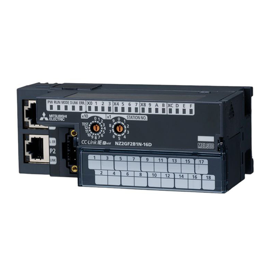
CHAPTER 3 PART NAMES CHAPTER 3 PART NAMES This section describes part names of the I/O module. • Main I/O module (screw terminal block type) *1 Do not remove this seal because it is used for a maintenance purpose. - Page 28 • Main I/O module (spring clamp terminal block type) *1 Do not remove this seal because it is used for a maintenance purpose.
- Page 29 CHAPTER 3 PART NAMES • Main I/O module (e-CON (16-point module)) *1 Do not remove this seal because it is used for a maintenance purpose.
- Page 30 • Main I/O module (e-CON (32-point module))
- Page 31 CHAPTER 3 PART NAMES • Main I/O module (MIL connector) *1 Do not remove this seal because it is used for a maintenance purpose.
- Page 32 • Extension I/O module (screw terminal block type) *1 Do not remove this seal because it is used for a maintenance purpose. *2 Do not remove this cover because it is used for a maintenance purpose.
- Page 33 CHAPTER 3 PART NAMES • Extension I/O module (spring clamp terminal block type) *1 Do not remove this seal because it is used for a maintenance purpose. *2 Do not remove this cover because it is used for a maintenance purpose.
- Page 34 Name Application A rotary switch for the following setting and test. • Station Number Setting ( Page 138, Section 7.1) Station number setting switch • Unit Test (Page 246, Section 12.4) When operating the station number setting switch, use a flathead screwdriver with 3.5mm or less width of the tip. Indicates the ON/OFF status of the inputs.
- Page 35 CHAPTER 3 PART NAMES (1) I/O module status and LED status The following table lists the correspondence between the I/O module status and the LED status. LED status I/O module status Data link status PW LED RUN LED MODE LED D LINK LED ERR.
-
Page 36: Chapter 4 Specifications
CHAPTER 4 SPECIFICATIONS This chapter describes the specifications of the I/O module. General Specifications Item Specifications Operating ambient 0 to 55 temperature Storage ambient -25 to 75 temperature Operating ambient humidity 5 to 95%RH, non-condensing Storage ambient humidity Constant Frequency Half amplitude Number of sweeps acceleration... -
Page 37: Main I/O Module Specifications
Main I/O Module Specifications 4.2.1 Main input module (1) NZ2GF2B1(N)-16D main DC input module (screw terminal block, positive common/negative common shared type) Item NZ2GF2B1-16D, NZ2GF2B1N-16D Station type Remote device station Number of input points 16 points Rated input voltage 24VDC (ripple rate: 5% or less) (Allowable voltage range: 20.4 to 28.8VDC) Rated input current 6.0mA TYP. - Page 38 Item NZ2GF2B1-16D, NZ2GF2B1N-16D Availability of connecting extension module Connectable (Max. one module) Voltage 24VDC (ripple rate: 5% or less) (Allowable voltage range: 20.4 to 28.8VDC) Module power supply Current 180mA or less (24VDC, all points ON) Weight 0.31kg If the input response time is set to "0ms", the actual input response time is 80s at OFF ON, and 140s at ON OFF.
- Page 39 CHAPTER 4 SPECIFICATIONS (2) NZ2GF2S1-16D main DC input module (spring clamp terminal block, positive common/negative common shared type) Item NZ2GF2S1-16D Station type Remote device station Number of input points 16 points Rated input voltage 24VDC (ripple rate: 5% or less) (Allowable voltage range: 20.4 to 28.8VDC) Rated input current 6.0mA TYP.
- Page 40 For how to calculate the processing time of the remote device station (input), refer to the point in the following. Page 35, Section 4.2.1 (1) If the input response time is set to "0ms", the actual input response time is 90s at OFF ON, and 140s at ON OFF. It is the noise immunity of when the input response time setting value is other than "0ms".
- Page 41 CHAPTER 4 SPECIFICATIONS (3) NZ2GFCE3-16D main DC input module (sensor connector (e-CON), positive common type) Item NZ2GFCE3-16D Station type Remote device station Number of input points 16 points Rated input voltage 24VDC (ripple rate: 5% or less) (Allowable voltage range: 20.4 to 28.8VDC) Rated input current 4.0mA TYP.
- Page 42 External connection Pin number Signal name CON A One-touch connector for power supply and FG Signal name +24V (UNIT) CON A Non-insulated UNIT POWER CABLE (IN) CON B 24G (UNIT) Module +24V (UNIT) power supply +24V (I/O) 24G (UNIT) +24V (I/O) I/O power supply 24G (I/O) 24G (I/O)
- Page 43 CHAPTER 4 SPECIFICATIONS External connection Derating chart • When an online connector is connected CON A One-touch connector for power supply and FG Signal name 16 points, 50 16 points, 55 UNIT POWER CABLE (IN) Module +24V (UNIT) power supply 12 points, 55 24G (UNIT) I/O power...
- Page 44 (4) NZ2GFCE3-32D main DC input module (sensor connector (e-CON), positive common type) Item NZ2GFCE3-32D Station type Remote device station Number of input points 32 points Rated input voltage 24VDC (ripple rate: 5% or less) (Allowable voltage range: 20.4 to 28.8VDC) Rated input current 4.0mA TYP.
- Page 45 CHAPTER 4 SPECIFICATIONS External connection Pin number Signal name CON A One-touch connector for power supply and FG Signal name +24V (UNIT) CON A Non-insulated UNIT POWER CABLE (IN) CON B 24G (UNIT) Module +24V (UNIT) power supply +24V (I/O) 24G (UNIT) +24V (I/O) I/O power supply...
- Page 46 External connection When an online connector is connected +24V +24V CON 9 (X8) (X18) CON A One-touch connector for power supply and FG Signal name +24V +24V UNIT POWER CABLE (IN) Module +24V (UNIT) power supply 24G (UNIT) (X9) (X19) I/O power +24V (I/O) supply...
- Page 47 CHAPTER 4 SPECIFICATIONS (5) NZ2GFCE3-16DE main DC input module (sensor connector (e-CON), negative common type) Item NZ2GFCE3-16DE Station type Remote device station Number of input points 16 points Rated input voltage 24VDC (ripple rate: 5% or less) (Allowable voltage range: 20.4 to 28.8VDC) Rated input current 4.0mA TYP.
- Page 48 External connection Pin number Signal name CON A One-touch connector +24V (UNIT) for power supply and FG Signal name CON A Non-insulated UNIT POWER CABLE (IN) CON B 24G (UNIT) Module +24V (UNIT) +24V (I/O) power supply 24G (UNIT) I/O power supply +24V (I/O) 24G (I/O) 24G (I/O)
- Page 49 CHAPTER 4 SPECIFICATIONS External connection Derating chart • When an online connector is connected CON A One-touch connector for power supply and FG Signal name 16 points, 50 16 points, 55 UNIT POWER CABLE (IN) Module +24V (UNIT) power supply 12 points, 55 24G (UNIT) I/O power...
- Page 50 (6) NZ2GFCM1-16D main DC input module (MIL connector, positive common type) Item NZ2GFCM1-16D Station type Remote device station Number of input points 16 points Rated input voltage 24VDC (ripple rate: 5% or less) (Allowable voltage range: 20.4 to 28.8VDC) Rated input current 4.0mA TYP.
- Page 51 CHAPTER 4 SPECIFICATIONS External connection CON A One-touch connector for power supply and FG Signal name Non-insulated UNIT POWER CABLE (IN) Module +24V (UNIT) • One-touch connector for power supply and FG power supply 24G (UNIT) I/O power +24V (I/O) supply 24G (I/O) I/O POWER CABLE (IN)
- Page 52 External connection Derating chart • When an online connector is connected CON A One-touch connector for power supply and FG Signal name 16 points, 50 16 points, 55 UNIT POWER CABLE (IN) Module +24V (UNIT) power supply 12 points, 55 24G (UNIT) I/O power Maximum...
- Page 53 CHAPTER 4 SPECIFICATIONS (7) NZ2GFCM1-16DE main DC input module (MIL connector, negative common type) Item NZ2GFCM1-16DE Station type Remote device station Number of input points 16 points Rated input voltage 24VDC (ripple rate: 5% or less) (Allowable voltage range: 20.4 to 28.8VDC) Rated input current 4.0mA TYP.
- Page 54 External connection CON A One-touch connector for power supply and FG Signal name Non-insulated UNIT POWER CABLE (IN) Module +24V (UNIT) • One-touch connector for power supply and FG power supply 24G (UNIT) I/O power +24V (I/O) supply 24G (I/O) I/O POWER CABLE (IN) CON B One-touch connector...
- Page 55 CHAPTER 4 SPECIFICATIONS External connection Derating chart • When an online connector is connected CON A One-touch connector for power supply and FG Signal name 16 points, 50 16 points, 55 UNIT POWER CABLE (IN) Module +24V (UNIT) power supply 12 points, 55 24G (UNIT) I/O power...
-
Page 56: Main Output Module
4.2.2 Main output module (1) NZ2GF2B1(N)-16T main transistor output module (screw terminal block, sink type) Item NZ2GF2B1-16T, NZ2GF2B1N-16T Station type Remote device station Number of output points 16 points Rated load voltage 12/24VDC (ripple rate: 5% or less) (Allowable voltage range: 10.2 to 28.8VDC) Max. - Page 57 CHAPTER 4 SPECIFICATIONS Item NZ2GF2B1-16T, NZ2GF2B1N-16T 16 points (1 + number of extension modules) RX/RY points Cyclic transmission RWr/RWw points 20 points An Ethernet cable that meets the 1000BASE-T standard: Communication cable Category 5e or higher (double shielded, STP), straight cable Availability of connecting extension module Connectable (Max.
- Page 58 External connection Connector for module Terminal block mounting screw power supply and FG UNIT POWER Signal name Non-insulated CABLE +24V Module power Terminal block mounting screw supply Terminal block Terminal block Pin number for output Signal name CTL+ Load Pin number Signal name COM- External power supply...
- Page 59 CHAPTER 4 SPECIFICATIONS (2) NZ2GF2S1-16T main transistor output module (spring clamp terminal block, sink type) Item NZ2GF2S1-16T Station type Remote device station Number of output points 16 points Rated load voltage 12/24VDC (ripple rate: 5% or less) (Allowable voltage range: 10.2 to 28.8VDC) Max.
- Page 60 Item NZ2GF2S1-16T Availability of connecting extension module Connectable (Max. one module) Voltage 24VDC (ripple rate: 5% or less) (Allowable voltage range: 20.4 to 28.8VDC) Module power supply Current 190mA or less (24VDC, all points ON) Weight 0.31kg For how to calculate the processing time of the remote device station (output), refer to the point in the following. (...
- Page 61 CHAPTER 4 SPECIFICATIONS (3) NZ2GF2B1(N)-16TE main transistor output module (screw terminal block, source type) Item NZ2GF2B1-16TE, NZ2GF2B1N-16TE Station type Remote device station Number of output points 16 points Rated load voltage 12/24VDC (ripple rate: 5% or less) (Allowable voltage range: 10.2 to 28.8VDC) Max.
- Page 62 Item NZ2GF2B1-16TE, NZ2GF2B1N-16TE Availability of connecting extension module Connectable (Max. one module) Voltage 24VDC (ripple rate: 5% or less) (Allowable voltage range: 20.4 to 28.8VDC) Module power supply Current 190mA or less (24VDC, all points ON) Weight 0.31kg For how to calculate the processing time of the remote device station (output), refer to the point in the following. (...
- Page 63 CHAPTER 4 SPECIFICATIONS (4) NZ2GF2S1-16TE main transistor output module (spring clamp terminal block, source type) Item NZ2GF2S1-16TE Station type Remote device station Number of output points 16 points Rated load voltage 12/24VDC (ripple rate: 5% or less) (Allowable voltage range: 10.2 to 28.8VDC) Max.
- Page 64 Item NZ2GF2S1-16TE Voltage 24VDC (ripple rate: 5% or less) (Allowable voltage range: 20.4 to 28.8VDC) Module power supply Current 190mA or less (24VDC, all points ON) Weight 0.31kg For how to calculate the processing time of the remote device station (output), refer to the point in the following. (...
- Page 65 CHAPTER 4 SPECIFICATIONS (5) NZ2GFCE3-16T main transistor output module (sensor connector (e-CON), sink type) Item NZ2GFCE3-16T Station type Remote device station Number of output points 16 points Rated load voltage 12/24VDC (ripple rate: 5% or less) (Allowable voltage range: 10.2 to 28.8VDC) Max.
- Page 66 External connection Pin number Signal name CON A One-touch connector +24V (UNIT) CON A for power supply and FG Signal name Non-insulated CON B UNIT POWER CABLE (IN) 24G (UNIT) Module +24V (UNIT) +24V (I/O) power supply 24G (UNIT) 24G (I/O) +24V (I/O) I/O power supply...
- Page 67 CHAPTER 4 SPECIFICATIONS External connection • When an online connector is connected CON A One-touch connector for power supply and FG Signal name UNIT POWER CABLE (IN) Module +24V (UNIT) power supply 24G (UNIT) I/O power +24V (I/O) supply 24G (I/O) I/O POWER CABLE (IN) CON B One-touch connector...
- Page 68 (6) NZ2GFCE3-32T main transistor output module (sensor connector (e-CON), sink type) Item NZ2GFCE3-32T Station type Remote device station Number of output points 32 points Rated load voltage 12/24VDC (ripple rate: 5% or less) (Allowable voltage range: 10.2 to 28.8VDC) Max. load current 0.5A/point, 6A/common Isolation method Photocoupler isolation...
- Page 69 CHAPTER 4 SPECIFICATIONS For how to calculate the processing time of the remote device station (output), refer to the point in the following. ( Page 54, Section 4.2.2 (1)) For details, refer to "Recommended Connector List". ( Page 19, Section 1.5) For how to calculate the current consumption when an extension module is connected, refer to "Calculating Current Consumption".
- Page 70 External connection When an online connector is connected +24V +24V CON 9 (Y8) (Y18) CON A One-touch connector for power supply and FG Signal name +24V +24V UNIT POWER CABLE (IN) Module +24V (UNIT) power supply 24G (UNIT) I/O power (Y9) (Y19) +24V (I/O)
- Page 71 CHAPTER 4 SPECIFICATIONS (7) NZ2GFCE3-16TE main transistor output module (sensor connector (e-CON), source type) Item NZ2GFCE3-16TE Station type Remote device station Number of output points 16 points Rated load voltage 12/24VDC (ripple rate: 5% or less) (Allowable voltage range: 10.2 to 28.8VDC) Max.
- Page 72 External connection Pin number Signal name CON A One-touch connector +24V (UNIT) CON A for power supply and FG Signal name CON B 24G (UNIT) Non-insulated UNIT POWER CABLE (IN) Module +24V (I/O) +24V (UNIT) power supply 24G (UNIT) 24G (I/O) I/O power +24V (I/O) supply...
- Page 73 CHAPTER 4 SPECIFICATIONS External connection • When an online connector is connected CON A One-touch connector for power supply and FG Signal name UNIT POWER CABLE (IN) Module +24V (UNIT) power supply 24G (UNIT) I/O power +24V (I/O) supply 24G (I/O) I/O POWER CABLE (IN) CON B One-touch connector...
- Page 74 (8) NZ2GFCM1-16T main transistor output module (MIL connector, sink type) Item NZ2GFCM1-16T Station type Remote device station Number of output points 16 points Rated load voltage 12/24VDC (ripple rate: 5% or less) (Allowable voltage range: 10.2 to 28.8VDC) Max. load current 0.5A/point, 2A/common Isolation method Photocoupler isolation...
- Page 75 CHAPTER 4 SPECIFICATIONS External connection CON A One-touch connector for power supply and FG Signal name Non-insulated UNIT POWER CABLE (IN) Module +24V (UNIT) power supply 24G (UNIT) I/O power +24V (I/O) supply 24G (I/O) I/O POWER CABLE (IN) CON B One-touch connector for power supply and FG Signal name...
- Page 76 (9) NZ2GFCM1-16TE main transistor output module (MIL connector, source type) Item NZ2GFCM1-16TE Station type Remote device station Number of output points 16 points Rated load voltage 12/24VDC (ripple rate: 5% or less) (Allowable voltage range: 10.2 to 28.8VDC) Max. load current 0.5A/point, 2A/common Isolation method Photocoupler isolation...
- Page 77 CHAPTER 4 SPECIFICATIONS External connection CON A One-touch connector for power supply and FG Signal name UNIT POWER CABLE (IN) Non-insulated Module +24V (UNIT) power supply 24G (UNIT) I/O power +24V (I/O) supply 24G (I/O) I/O POWER CABLE (IN) CON B One-touch connector for power supply and FG Signal name...
-
Page 78: I/O Combined Module
4.2.3 I/O combined module (1) NZ2GFCE3-32DT main DC input/transistor output module (sensor connector (e-CON), positive common, sink type) NZ2GFCE3-32DT Item Input specifications Output specifications Station type Remote device station Number of input points 16 points 24VDC (ripple rate: 5% or less) (Allowable voltage Rated input voltage range: 20.4 to 28.8VDC) Rated input current... - Page 79 CHAPTER 4 SPECIFICATIONS NZ2GFCE3-32DT Item Input specifications Output specifications Applicable DIN rail TH35-7.5Fe, TH35-7.5Al (compliant with IEC 60715) 0.66 to 0.98 (18 AWG) [Finishing outer diameter: 2.2 to 3.0mm (A6CON-PW5P), 2.0 to 2.3mm (A6CON-PW5P-SOD)] For power supply Strand diameter: 0.16mm or larger Applicable wire size Insulating coating material: PVC (heat resistant vinyl) 0.08 to 0.5...
- Page 80 External connection Pin number Signal name CON A One-touch connector +24V (UNIT) CON A for power supply and FG Signal name Non-insulated CON B UNIT POWER CABLE (IN) 24G (UNIT) Module +24V (UNIT) +24V (I/O) power supply 24G (UNIT) 24G (I/O) +24V (I/O) I/O power supply...
- Page 81 CHAPTER 4 SPECIFICATIONS External connection When an online connector is connected +24V +24V CON 9 (X8) (Y18) CON A One-touch connector for power supply and FG Signal name UNIT POWER CABLE (IN) +24V +24V Module +24V (UNIT) power supply 24G (UNIT) I/O power +24V (I/O) (X9)
-
Page 82: Extension I/O Module Specifications
Extension I/O Module Specifications 4.3.1 Extension input module (1) NZ2EX2B1-16D extension DC input module (screw terminal block, positive common/negative common shared type) Item NZ2EX2B1-16D Number of input points 16 points Rated input voltage 24VDC (ripple rate: 5% or less) (Allowable voltage range: 20.4 to 28.8VDC) Rated input current 6.0mA TYP. - Page 83 CHAPTER 4 SPECIFICATIONS ● How to calculate the processing time of the remote device station (input) The processing time of the remote device station (input) is the time period for internal processing of the remote device station (input). The value of the processing time of the remote device station (input) is used in the calculation for the delay time of the cyclic transmission from the remote device station (input) to the master station (RX/RWr).
- Page 84 (2) NZ2EX2S1-16D extension DC input module (spring clamp terminal block, positive common/negative common shared type) Item NZ2EX2S1-16D Number of input points 16 points Rated input voltage 24VDC (ripple rate: 5% or less) (Allowable voltage range: 20.4 to 28.8VDC) Rated input current 6.0mA TYP.
- Page 85 CHAPTER 4 SPECIFICATIONS For how to calculate the processing time of the remote device station (input), refer to the point in the following. (Page 80, Section 4.3.1 (1)) If the input response time is set to "0ms", the actual input response time is 90s at OFF ON, and 140s at ON OFF. It is the noise immunity of when the input response time setting value is other than "0ms".
-
Page 86: Extension Output Module
4.3.2 Extension output module (1) NZ2EX2B1-16T extension transistor output module (screw terminal block, sink type) Item NZ2EX2B1-16T Number of output points 16 points Rated load voltage 12/24VDC (ripple rate: 5% or less) (Allowable voltage range: 10.2 to 28.8VDC) Max. load current 0.5A/point, 4A/common Isolation method Photocoupler isolation... - Page 87 CHAPTER 4 SPECIFICATIONS ● How to calculate the processing time of the remote device station (output) The processing time of the remote device station (output) is the time period for internal processing of the remote device station (output). The value of the processing time of the remote device station (output) is used in the calculation for the delay time of the cyclic transmission from the master station (RY/RWw) to the remote device station (output).
- Page 88 (2) NZ2EX2S1-16T extension transistor output module (spring clamp terminal block, sink type) Item NZ2EX2S1-16T Number of output points 16 points Rated load voltage 12/24VDC (ripple rate: 5% or less) (Allowable voltage range: 10.2 to 28.8VDC) Max. load current 0.5A/point, 4A/common Isolation method Photocoupler isolation Max.
- Page 89 CHAPTER 4 SPECIFICATIONS For how to calculate the processing time of the remote device station (output), refer to the point in the following. Page 84, Section 4.3.2 (1) Using bar solderless terminals is recommended for wiring. Only one wire can be connected to a wire insertion opening. Multiple wires cannot be connected to a terminal. Connecting two or more wires may cause a poor contact.
- Page 90 (3) NZ2EX2B1-16TE extension transistor output module (screw terminal block, source type) Item NZ2EX2B1-16TE Number of output points 16 points Rated load voltage 12/24VDC (ripple rate: 5% or less) (Allowable voltage range: 10.2 to 28.8VDC) Max. load current 0.5A/point, 4A/common Isolation method Photocoupler isolation Max.
- Page 91 CHAPTER 4 SPECIFICATIONS External connection Terminal block Terminal block mounting screw for output Load Terminal block mounting screw Terminal block Pin number Signal name COM+ Pin number Signal name CTL- Load power supply Load COM+ CTL- Constant-voltage External power circuit supply for the output part Load...
- Page 92 (4) NZ2EX2S1-16TE extension transistor output module (spring clamp terminal block, source type) Item NZ2EX2S1-16TE Number of output points 16 points Rated load voltage 12/24VDC (ripple rate: 5% or less) (Allowable voltage range: 10.2 to 28.8VDC) Max. load current 0.5A/point, 4A/common Isolation method Photocoupler isolation Max.
- Page 93 CHAPTER 4 SPECIFICATIONS For how to calculate the processing time of the remote device station (output), refer to the point in the following. Page 84, Section 4.3.2 (1) Using bar solderless terminals is recommended for wiring. Only one wire can be connected to a wire insertion opening. Multiple wires cannot be connected to a terminal. Connecting two or more wires may cause a poor contact.
-
Page 94: Calculating Current Consumption
Calculating Current Consumption (1) Total current consumption of modules The total current consumption of the modules is calculated by summing the module power supply current in the main module and extension module. The total current consumption must not exceed 0.36A. For the value of the module power supply current, refer to the specifications of each module. - Page 95 CHAPTER 4 SPECIFICATIONS (2) Precautions for transition wiring of the one-touch connector for power supply and FG Current flows in the modules when they are transition wired through one-touch connectors for power supply and FG. Design the system so that the current equals to or lower than the maximum rated current shown below. Input module (example: NZ2GFCE3-16D) Output module (example: NZ2GFCE3-16T) CON A...
-
Page 96: Function List
Function List This section lists the functions of I/O modules. : Available, : Not available Availability Extension Main Main Main I/O Extension Item Description Reference Digital input output combined input Output module module module module Module The number of input points or output points Extension module can be increased by connecting an extension ... - Page 97 CHAPTER 4 SPECIFICATIONS Availability Extension Main Main Main I/O Extension Item Description Reference Digital input output combined input Output module module module module Module This function performs I/O operations with a synchronization cycle of the master station CC-Link IE Field that supports the CC-Link IE Field Network Page 198, Network synchronous...
-
Page 98: List Of Remote I/O Signals
List of Remote I/O Signals This section lists I/O signals for a master/local module. The I/O signals shown are the example with the remote I/O signals of the I/O module assigned to the I/O numbers of RX0 to RX2F and RY0 to RY2F. Remote input (RX) indicates the input signal from the I/O module to the master/local module. -
Page 99: Main I/O Module
CHAPTER 4 SPECIFICATIONS 4.6.1 Main I/O module (1) Main input module (a) 16-point module Remote input Remote output Signal direction: Input module Master/local module Signal direction: Master/local module Input module Device number Description Device number Description External input signal X0 External input signal X1 External input signal X2 External input signal X3... - Page 100 (b) 32-point module Remote input Remote output Signal direction: Input module Master/local module Signal direction: Master/local module Input module Device number Description Device number Description External input signal X0 External input signal X1 External input signal X2 External input signal X3 External input signal X4 External input signal X5 External input signal X6...
- Page 101 CHAPTER 4 SPECIFICATIONS (2) Main output module (a) 16-point module Remote input Remote output Signal direction: Output module Master/local module Signal direction: Master/local module Output module Device number Description Device number Description External output signal Y0 External output signal Y1 External output signal Y2 External output signal Y3 External output signal Y4...
- Page 102 (b) 32-point module Remote input Remote output Signal direction: Output module Master/local module Signal direction: Master/local module Output module Device number Description Device number Description External output signal Y0 External output signal Y1 External output signal Y2 External output signal Y3 External output signal Y4 External output signal Y5 External output signal Y6...
- Page 103 CHAPTER 4 SPECIFICATIONS (3) Main I/O combined module Remote input Remote output Signal direction: I/O module Master/local module Signal direction: Master/local module I/O module Device number Description Device number Description External input signal X0 External input signal X1 External input signal X2 External input signal X3 External input signal X4...
-
Page 104: Extension I/O Module
4.6.2 Extension I/O module (1) Extension input module (a) When connected to a main I/O module (16-point module) Remote input Remote output Signal direction: Input module Master/local module Signal direction: Master/local module Input module Device number Description Device number Description RX10 External input signal X10... - Page 105 CHAPTER 4 SPECIFICATIONS (b) When connected to a main I/O module (32-point module) Remote input Remote output Signal direction: Input module Master/local module Signal direction: Master/local module Input module Device number Description Device number Description RX20 External input signal X20 RY20 RX21 External input signal X21...
- Page 106 (2) Extension Digital Output Module (a) When connected to a main I/O module (16-point module) Remote input Remote output Signal direction: Output module Master/local module Signal direction: Master/local module Output module Device number Description Device number Description RX10 RY10 External output signal Y10 RX11...
- Page 107 CHAPTER 4 SPECIFICATIONS (b) When connected to a main I/O module (32-point module) Remote input Remote output Signal direction: Output module Master/local module Signal direction: Master/local module Output module Device number Description Device number Description RX20 RY20 External output signal Y20 RX21 RY21 External output signal Y21...
-
Page 108: List Of Remote Register
List of Remote Register This section lists remote registers for a master/local module. The remote registers shown are the example with the remote registers of the I/O module assigned to the remote registers of RWr0 to RWr33 and RWw0 to RWw33. The remote registers are assigned in station-based units regardless of the main module or extension module. - Page 109 CHAPTER 4 SPECIFICATIONS Remote register (RWr) Remote register (RWw) Signal direction: I/O module Master/local module Signal direction: Master/local module I/O module Device number Name Device number Name Synchronous input timing information X6 OFF to ON RWw20 Use prohibited RWr20 Synchronous input timing information X6 ON to OFF RWw21...
- Page 110 (2) Main output module Remote register (RWr) Remote register (RWw) Signal direction: I/O module Master/local module Signal direction: Master/local module I/O module Device number Name Device number Name RWr0 Module status area RWw0 Module operation area RWr1 Error code RWw1 Use prohibited RWr2...
- Page 111 CHAPTER 4 SPECIFICATIONS Remote register (RWr) Remote register (RWw) Signal direction: I/O module Master/local module Signal direction: Master/local module I/O module Device number Name Device number Name RWr2B Use prohibited Synchronous output timing setting YB ON to OFF RWw2B RWr2C Use prohibited...
- Page 112 (3) Main I/O combined module Remote register (RWr) Remote register (RWw) Signal direction: I/O combined module Master/local module Signal direction: Master/local module I/O combined module Device No. Name Device number Name RWr0 Module status area RWw0 Module operation area RWr1 Error code RWw1...
- Page 113 CHAPTER 4 SPECIFICATIONS Remote register (RWr) Remote register (RWw) Signal direction: I/O combined module Master/local module Signal direction: Master/local module I/O combined module Device No. Name Device number Name RWr2E Use prohibited RWw2E Use prohibited RWr2F Use prohibited RWw2F Use prohibited RWr30...
-
Page 114: List Of Remote Buffer Memory
List of Remote Buffer Memory This section lists the remote buffer memory areas of the I/O module. The remote buffer memory areas of the main I/O module and extension I/O module are assigned as shown below. Main I/O module Extension I/O module 1 Example of the remote buffer memory in the manual Input response time setting (address: 0000H) Address of a main I/O module... - Page 115 CHAPTER 4 SPECIFICATIONS For details on the remote buffer memory, refer to the following. • Details of Remote Buffer Memory Addresses ( Page 269, Appendix 3) : Available, : Not available Address Access method REMFR instruction, CC IE Field Area Target REMTO Decimal...
-
Page 116: Main I/O Module
4.8.1 Main I/O module (1) Parameter area (address: 0000H to 04FFH) For the parameter area, parameters can be set by means of the CC IE Field configuration of the engineering tool, or the REMTO instruction. The parameter in the parameter area is backed up to the nonvolatile memory. However, Fast logic setting Y... - Page 117 CHAPTER 4 SPECIFICATIONS (a) Main input module Address Input module Type Decimal Hexadecimal Name Default value Read/Write 0000H Input response time setting 0005H 0001H Output HOLD/CLEAR setting 0000H 0002H Cyclic data update watch time setting 0000H Station-based parameter 0003H Mode switch 0009H data 0004H...
- Page 118 Address Input module Type Decimal Hexadecimal Name Default value Read/Write 0130H 0131H 0132H 0133H 0134H 0135H 0136H 0137H 0138H 0139H 013AH 013BH 013CH 013DH 013EH Input OFF delay setting X10 013FH to X1F (use prohibited for Main module modules other than the 0140H Module-based parameter NZ2GFCE3-32D)
- Page 119 CHAPTER 4 SPECIFICATIONS (b) Main output module Address Output module Type Decimal Hexadecimal Name Default value Read/Write 0000H Input response time setting 0005H 0001H Output HOLD/CLEAR setting 0000H 0002H Cyclic data update watch time setting 0000H Station-based parameter 0003H Mode switch 0009H data 0004H...
- Page 120 (c) Main I/O combined module Address I/O module Type Decimal Hexadecimal Name Default value Read/Write 0000H Input response time setting 0005H 0001H Output HOLD/CLEAR setting 0000H 0002H Cyclic data update watch time setting 0000H Station-based parameter 0003H Mode switch 0009H data 0004H Initial operation setting...
- Page 121 CHAPTER 4 SPECIFICATIONS Address I/O module Type Decimal Hexadecimal Name Default value Read/Write 0130H 0131H 0132H 0133H 0134H 0135H 0136H 0137H Fast logic setting Main module 0138H Module-based parameter 0139H data 013AH 013BH 013CH 013DH 013EH 013FH 0140H to 320 to 511 System area ...
- Page 122 (2) Monitoring area (address: 0500H to 09FFH) (a) Main input module Address Input module Type Decimal Hexadecimal Name Default value Read/Write 0500H to Station-based monitor data 1280 to 1535 System area 05FFH Main module 0600H to 1536 to 1791 System area Module-based monitor data...
- Page 123 CHAPTER 4 SPECIFICATIONS (b) Main output module Address Output module Type Decimal Hexadecimal Name Default value Read/Write 0500H to Station-based monitor data 1280 to 1535 System area 05FFH 1536 0600H System area 1537 0601H 1538 0602H Fast logic enable status 0603H to...
- Page 124 Address Output module Type Decimal Hexadecimal Name Default value Read/Write 1589 0630H 1590 0631H 1591 0632H 1592 0633H 1593 0634H 1594 0635H 1595 0636H 1596 0637H 1597 0638H 1598 0639H 1599 063AH 1600 063BH 1601 063CH ...
- Page 125 CHAPTER 4 SPECIFICATIONS (c) Main I/O combined module Address I/O module Type Decimal Hexadecimal Name Default value Read/Write 0500H to Station-based monitor data 1280 to 1535 System area 05FFH 0600H to 1536 to 1538 System area 0602H ...
- Page 126 (3) Error history area (address: 0A00H to 0FFFH) (a) Main input module, main output module, and main I/O combined module Address Input module and output module Type Decimal Hexadecimal Name Default value Read/Write 2560 0A00H Error code 0000H 2561 0A01H Order of generation 0000H [Error time] First two digits of...
- Page 127 CHAPTER 4 SPECIFICATIONS This is the value of factory default or the value of initialization by Error history clear command (address: 1000H). This shows whether reading/writing data from/to a program is possible. R: Readable W: Writable (4) Module control data area (address: 1000H to 14FFH) (a) Main input module Address Input module...
- Page 128 (b) Main output module Address Output module Type Decimal Hexadecimal Name Default value Read/Write 4096 1000H Error history clear command 0000H 4097 1001H Error history clear completed 0000H 4098 1002H Parameter area initialization command 0000H 4099 1003H Parameter area initialization completed 0000H Module operation information initialization Station-based control data...
- Page 129 CHAPTER 4 SPECIFICATIONS (c) Main I/O combined module Address I/O module Type Decimal Hexadecimal Name Default value Read/Write 4096 1000H Error history clear command 0000H 4097 1001H Error history clear completed 0000H 4098 1002H Parameter area initialization command 0000H 4099 1003H Parameter area initialization completed 0000H...
-
Page 130: Extension I/O Module
4.8.2 Extension I/O module (1) Parameter area (address: 0200H to 02FFH) (a) Extension input module Address Input module Type Decimal Hexadecimal Name Default value Read/Write 0200H Extension module identification code 0000H 0201H to 513 to 527 System area 020FH 0210H X10, X20... - Page 131 CHAPTER 4 SPECIFICATIONS (b) Extension output module Address Output module Type Decimal Hexadecimal Name Default value Read/Write 0200H Extension module identification code 0000H 0201H System area Number of ON times integration function 0202H 0000H enable 0203H to ...
- Page 132 (2) Monitoring area (address: 0700H to 07FFH) (a) Extension input module Address Input module Type Decimal Hexadecimal Name Default value Read/Write 1792 0700H Extension module identification code Module-based monitor data 0701H to 1793 to 2047 System area 07FFH Default values are not determined in the monitoring area.
- Page 133 CHAPTER 4 SPECIFICATIONS (b) Extension output module Address Output module Type Decimal Hexadecimal Name Default value Read/Write 1792 0700H Extension module identification code 1793 0701H System area 1794 0702H Fast logic enable status 0703H to ...
- Page 134 (3) Module control data area (address: 1200H to 12FFH) (a) Extension input module Address Input module Type Decimal Hexadecimal Name Default value Read/Write 1200H to Module-based control data 4608 to 4863 System area 12FFH This is the value for when the module power supply is turned off and on or at the remote reset. This shows whether reading/writing data from/to a program is possible.
-
Page 135: Chapter 5 Procedures Before Operation
CHAPTER 5 PROCEDURES BEFORE OPERATION CHAPTER 5 PROCEDURES BEFORE OPERATION This chapter describes the procedures before operation. Check box Station number setting Page 138, Section 7.1 Set the station number for an I/O module. Installation Page 139, Section 7.2 When using an extension module, connect the extension module to the Page 141, Section 7.3 main module. - Page 136 Memo...
-
Page 137: Chapter 6 System Configuration
CHAPTER 6 SYSTEM CONFIGURATION CHAPTER 6 SYSTEM CONFIGURATION This chapter describes system configuration using an I/O module. For CC-Link IE Field Network configuration, refer to the following. User's manual for the master/local module used I/O Module System Configuration The following shows system configuration using an I/O module. Main I/O module Extension I/O module... -
Page 138: Applicable Systems
Configuring and diagnosing the I/O module requires GX Works2 or GX Works3. Install GX Works2 or GX Works3 with the following version in accordance with the I/O module used. Software version Main I/O module GX Works2 GX Works3 NZ2GF2B1-16D NZ2GF2B1N-16D Version 1.91V or later NZ2GF2B1-16T Version 1.000A or later NZ2GF2B1N-16T NZ2GF2B1-16TE Version 1.98C or later... - Page 139 CHAPTER 6 SYSTEM CONFIGURATION Software version Extension I/O module GX Works2 GX Works3 NZ2EX2B1-16D Version 1.91V or later NZ2EX2B1-16T Version 1.000A or later NZ2EX2B1-16TE Version 1.98C or later NZ2EX2S1-16D NZ2EX2S1-16T Version 1.530C or later Version 1.007H or later NZ2EX2S1-16TE...
-
Page 140: Chapter 7 Installation And Wiring
CHAPTER 7 INSTALLATION AND WIRING This chapter describes the installation and wiring of the I/O module. Station Number Setting (1) Setting procedure Set the station number with the rotary switch on the front of the module. The setting value of the station number becomes valid when the module is powered on. -
Page 141: Installation Environment And Installation Position
CHAPTER 7 INSTALLATION AND WIRING Installation Environment and Installation Position 7.2.1 Installation environment (1) Installation location Do not install the I/O module to the place where: • Ambient temperature is outside the range of 0 to 55; • Ambient humidity is outside the range of 10 to 90% RH; •... -
Page 142: Installation Direction
7.2.3 Installation direction The I/O module can be installed in six directions. Use the DIN rail to install the module. Downward installation DIN rail Horizontal installation Vertical installation Horizontal installation (upside down) Upward installation... -
Page 143: Installation
CHAPTER 7 INSTALLATION AND WIRING Installation 7.3.1 Connecting extension modules (1) Connecting procedure Remove the cover on the side of the main module. Do not dispose the removed cover, but store it. Release the module joint levers (two points) on the side of the extension module. - Page 144 (2) Removal procedure Disconnect the modules by reversing the procedure above. ● Shut off the external power supply for the system in all phases before connecting or disconnecting extension modules. ● Lock the module joint levers securely. Failure to do so may cause malfunction, failure, or drop of the module.
-
Page 145: Mounting The Modules On A Din Rail
CHAPTER 7 INSTALLATION AND WIRING 7.3.2 Mounting the modules on a DIN rail An example of the use of the DIN rail stopper is described in the following procedure. Fix the module according to the manual of the DIN rail stopper used. (1) Mounting procedure Pull down all DIN rail hooks on the back of the modules. - Page 146 Hitch the upper hook of the DIN rail stopper to the Hitch the hook to top of the DIN rail. top of the DIN rail. Slide the DIN rail stopper up to the left side of the DIN rail modules. stopper Hold the DIN rail stopper in the direction opposite to DIN rail...
- Page 147 CHAPTER 7 INSTALLATION AND WIRING (2) Removal procedure Remove the modules from the DIN rail by reversing the above procedure. (3) Applicable DIN rail model (compliant with IEC 60715) • TH35-7.5Fe • TH35-7.5Al (4) Interval between DIN rail mounting screws Tighten the screws at intervals of 200mm or less.
-
Page 148: Wiring With Terminal Block For Module Power Supply And Fg
Wiring with Terminal Block for Module Power Supply and FG 7.4.1 Wiring with Terminal Block for Module Power Supply and FG (1) Tightening torque Tighten the terminal block screws within the following specified torque range. Tightening the screws too much may damage the module case. Screw type Tightening torque range Terminal block mounting screw (M2.5 screw) - Page 149 CHAPTER 7 INSTALLATION AND WIRING (4) Connecting and disconnecting the cable To connect a cable, with the terminal screw loosened using a flathead screwdriver, insert the wire and then tighten the terminal screw. To disconnect the cable, with the terminal screw loosened using a flathead screwdriver, pull out the wire. (5) Processing method of the cable terminal Strip the cable about 10mm from the top.
-
Page 150: Wiring For Spring Clamp Terminal Block Type
7.4.2 Wiring for Spring Clamp Terminal Block Type (1) Tightening torque Tighten the terminal block mounting screws within the following specified torque range. Tightening the screws too much may damage the module case. Screw type Tightening torque range Terminal block mounting screw (M2.5 screw) 0.2 to 0.3 Nm (2) Wire to be used The following table describes the wire to be connected to the terminal block for module power supply and FG. - Page 151 CHAPTER 7 INSTALLATION AND WIRING To disconnect the cable, push in the open/close button with a Phillips screwdriver or flathead screwdriver. With the button pushed in, pull out the wire having a bar solderless terminal. (a) Precautions • Use a bar solderless terminal for the wiring to the push-in type spring clamp terminal block. If a stripped wire is inserted into a wire insertion opening, the wire cannot be securely clamped.
- Page 152 AI 0.5-8WH, AI 0.5-10WH 0.5 AI 0.75-8GY, AI 0.75-10GY 0.75 CRIMPFOX6 Phoenix Contact Co., Ltd. AI 1-8RD, AI 1-10RD 1.0 AI 1.5-8BK, AI 1.5-10BK 1.5 FA-VTC125T9 0.3 to 1.65 Your local Mitsubishi Electric FA-NH65A sales office or representative FA-VTCW125T9 0.3 to 1.6...
-
Page 153: Wiring Of The One-Touch Connector For Power Supply And Fg
CHAPTER 7 INSTALLATION AND WIRING Wiring of the One-touch Connector for Power Supply and FG (1) Wiring procedure Check that the plug cover is engaged with the plug Plug cover body. Plug body Do not push the plug cover into the plug body before inserting cables. - Page 154 Example of correct crimping Check that the plug body and plug cover are aligned horizontally seen from the wire side. The floating part of the plug cover must be within 0.2mm. As shown in the example of incorrect crimping, if the plug cover is lifted aslant or protruded from the plug body by more than 0.2mm, it may result in improper crimping.
-
Page 155: Wiring Of Ethernet Cable
CHAPTER 7 INSTALLATION AND WIRING Wiring of Ethernet Cable (1) Connecting the Ethernet cable (a) Connecting Power off the power supplies of the main I/O module and the external device. Push the Ethernet cable connector into the main I/O module until it clicks. Pay attention to the connector's direction. - Page 156 ● PORT1 and PORT2 need not to be distinguished. When only one connector is used in star topology, either PORT1 or PORT2 can be connected. Either one can be used. ● When two connectors are used in line topology or ring topology, an Ethernet cable can be connected to the connectors in any combination.
- Page 157 CHAPTER 7 INSTALLATION AND WIRING (2) Precautions (a) Laying Ethernet cables • Place the Ethernet cable in a duct or clamp them. If not, dangling cable may swing or inadvertently be pulled, resulting in damage to the module or cables or malfunction due to poor contact. •...
-
Page 158: Wiring Of External Device And I/O Terminal Block
Wiring of External Device and I/O Terminal Block 7.7.1 Wiring for the screw terminal block type (1) Tightening torque Tighten the terminal block screws within the following specified torque range. Tightening the screws too much may damage the module case. Screw type Tightening torque range Terminal screw (M3 screw ... - Page 159 CHAPTER 7 INSTALLATION AND WIRING (b) Installation procedure Open the terminal cover to install the terminal block. Tighten the terminal block mounting screws. Terminal block mounting screw (3) Wiring of the external device and terminal block (a) Signal name and wiring For the signal names of the terminal block and wiring of the external device, refer to the section about external connection in specifications of each module.
-
Page 160: Wiring For Spring Clamp Terminal Block Type
7.7.2 Wiring for Spring Clamp Terminal Block Type (1) Tightening torque Tighten the terminal block mounting screws within the following specified torque range. Tightening the screws too much may damage the module case. Screw type Tightening torque range Terminal block mounting screw (M3.5 screw) 0.68 to 0.92Nm The following table shows applicable bar solderless terminals connected to the terminal block. - Page 161 CHAPTER 7 INSTALLATION AND WIRING (3) Wiring of the external device and terminal block (a) Signal name and wiring For the signal names of the terminal block and wiring of the external device, refer to the section about external connection in specifications of each module. (...
-
Page 162: Chapter 8 Various Settings
● To select a main module listed below in the "CC IE Field Configuration" window, select the following models from the "Module List" window. Module model name Selection for the "CC IE Field Configuration" window. NZ2GF2B1N-16D NZ2GF2B1-16D NZ2GF2B1N-16T NZ2GF2B1-16T NZ2GF2B1N-16TE NZ2GF2B1-16TE... - Page 163 CHAPTER 8 VARIOUS SETTINGS (1) Precautions (a) Precautions before parameter settings • Write or read the parameter settings of this module when the CPU module is in STOP status. The parameter settings cannot be written or read when the CPU module is in RUN status. •...
- Page 164 (2) Operation procedure Open the "CC IE Field Configuration" window. • For the master/local module QJ71GF11-T2 Project window [Parameter] [Network Parameter] [Ethernet/CC IE/MELSECNET] button • For the master/local module LJ71GF11-T2 Project window [Parameter] [Network Parameter] [Ethernet/CC IE Field] ...
- Page 165 CHAPTER 8 VARIOUS SETTINGS Double-click the item to change the setting, and input the setting value. • Items to input from the pull-down list Double-click the item to set, to display the pull-down list. Select the item. • Items to input from the text box Double-click the item to set, and input the setting value.
- Page 166 Module type Setting item Reference Input OFF delay setting X10 Input OFF delay setting X11 Input OFF delay setting X12 Input OFF delay setting X13 Input OFF delay setting X14 Input OFF delay setting X15 Input OFF delay setting X16 Main input module, Input OFF delay setting X17 main I/O combined...
- Page 167 CHAPTER 8 VARIOUS SETTINGS Module type Setting item Reference Number of ON times integration function enable Y10 Number of ON times integration function enable Y11 Number of ON times integration function enable Y12 Number of ON times integration function enable Y13 Number of ON times integration function enable Y14 Number of ON times integration function enable Y15 Number of ON times integration function enable Y16...
- Page 168 Module type Setting item Reference Extension 1_Number of ON times integration function enable Y0 Extension 1_Number of ON times integration function enable Y1 Extension 1_Number of ON times integration function enable Y2 Extension 1_Number of ON times integration function enable Y3 Extension 1_Number of ON times integration function enable Y4 Extension 1_Number of ON times integration function...
- Page 169 CHAPTER 8 VARIOUS SETTINGS Click the button and the following window is displayed. Click the button. The parameter is written to the I/O module. ● Set all the items for the parameter. If any blank exists, the parameter cannot be written to the I/O module. ●...
-
Page 170: Changing The Parameter
Changing the Parameter This section describes the procedure for changing the parameter. The precautions for changing the parameter are the same as those in the following section. • Precautions ( Page 161, Section 8.1 (1)) 8.2.1 Changing the network configuration When changing the network configuration diverting the created project, set the parameter in the following procedure. - Page 171 CHAPTER 8 VARIOUS SETTINGS Select the I/O module in "List of stations" on the "CC IE Field Configuration" window. List of stations Open the "Parameter Processing of Slave Station" window. [CC IE Field Configuration] [Online] [Parameter Processing of Slave Station] Set "Method selection"...
- Page 172 Set "Method selection" to "Parameter write". Set "Write Value". The following are the procedure. • Click the title cell of "Read Value" to select all the items and copy them. • Click the title cell of "Write Value" to select all the items and paste the copy. •...
- Page 173 CHAPTER 8 VARIOUS SETTINGS Click the button to display the refresh parameter setting window. Set the refresh parameter. Change the value as necessary. Write the set parameter to the CPU module of the master station and reset the CPU module. RESET Change the status of the CPU module of the master station to RUN.
-
Page 174: Changing The Parameter Without Changing The Network Configuration
8.2.2 Changing the parameter without changing the network configuration To change only the created module parameter of the slave station without changing the network configuration, set the parameter in the following procedure. Open the "CC IE Field Configuration" window. • For the master/local module QJ71GF11-T2 Project window ... - Page 175 CHAPTER 8 VARIOUS SETTINGS Click the button and the following window is displayed. Click the button. The parameter is read from the I/O module. Set "Method selection" to "Parameter write". Set "Write Value". The following are the procedure. • Click the title cell of "Read Value" to select all the items and copy them. •...
- Page 176 Click the button and the following window is displayed. Click the button. The parameter is written to the I/O module. The module parameter setting of the slave station is completed.
-
Page 177: Chapter 9 Functions
CHAPTER 9 FUNCTIONS CHAPTER 9 FUNCTIONS This chapter describes the details of the functions available in the I/O module, and the setting procedures for those functions. For details on remote I/O signals, remote registers, and remote buffer memory, refer to the following. •... -
Page 178: Drive Mode Switch
Drive Mode Switch The drive modes of the I/O module are the normal mode and synchronous communication mode. The following table lists the type and the operation of the mode. Type Operation Normal mode I/O is performed based on the internal clock of the I/O module. I/O is performed with a synchronization cycle of the master station that supports the CC-Link IE Field Network Synchronous communication mode synchronous communication function. - Page 179 CHAPTER 9 FUNCTIONS Check that "0204H" is stored in Latest warning code (RWr2). [Online] [Monitor] [Device/Buffer Memory Batch] The main I/O module starts operating in the set drive mode by turning off and on the power or performing the remote reset. ●...
-
Page 180: Error Notification Function
Error Notification Function When an error or warning occurs, the I/O module notifies the master station of it using remote registers. Remark The notification of the error or warning can be checked on the LED on the front of the module. For details, refer to the following. - Page 181 CHAPTER 9 FUNCTIONS (a) Method for clearing a warning Error type Clearing an error Minor error Warning A warning is cleared five seconds after the error cause is removed. A warning results in the following state five seconds after the error cause is removed. •...
- Page 182 (3) Method for clearing an error by executing the command of the slave station The following shows how to clear an error by executing the command of the slave station. Select the main I/O module in "List of stations" on the "CC IE Field Configuration"...
-
Page 183: Input Off Delay Function
CHAPTER 9 FUNCTIONS Input OFF Delay Function This function turns off an X signal after a predetermined time passed from when an actual input becomes off from on. With the input OFF delay function, even an input whose ON time is extremely short can be surely recognized on a program. - Page 184 ● The delay time does not include the hardware response time. ● The accuracy of the delay time is 0 to 400s. (1) Setting procedure Set "Method selection" to "Parameter write". "CC IE Field Configuration" window Select a main I/O module in "List of stations". [CC IE Field Configuration] ...
-
Page 185: Input Response Time Setting Function
CHAPTER 9 FUNCTIONS Input Response Time Setting Function This function prevents an incorrect input due to noise by setting the response time until the module recognizes an actual input as the X signal. The input response time can be set from the module parameter setting window of the engineering tool or the program. (1) Setting procedure Set "Method selection"... -
Page 186: Output Hold/Clear Setting Function
Output HOLD/CLEAR Setting Function When the I/O module is disconnected from data link, or the CPU module operating status is STOP, whether to hold or clear the last output value can be set. Set whether to hold or clear the values for all the output points of the module in a batch from the module parameter setting window of the engineering tool or the program. -
Page 187: Cyclic Data Update Watch Function
CHAPTER 9 FUNCTIONS Cyclic Data Update Watch Function The update intervals of cyclic data are monitored. The last output value is held or cleared when the cyclic transmission stop status continues longer than the set monitoring time. The cyclic transmission stop status is the status that the D LINK LED is flashing (Data link in operation (cyclic transmission stopped)) or off (Data link not performed (disconnected)). -
Page 188: Number Of On Times Integration Function
Number of ON Times Integration Function The number of ON times of each output point is counted within the range of 0 to 2147483647. The integration value remains even though the output module is powered off. Whether to enable or disable the function can be set for each output point from the module parameter setting window of the engineering tool or the program. - Page 189 CHAPTER 9 FUNCTIONS (2) Checking and clearing the number of ON times The number of ON times can be checked and cleared on the program. Item Description Reference Program Example • Page 214, Section 10.3 Number of ON times integration value Y Stores the integration value of the number of ON times integration Details of Remote Buffer Memory (address: 0610H to 064FH, 0710H to 072FH)
-
Page 190: Output On/Off Information Hold Function
The output on/off information hold function cannot be used depending on the combination of the I/O module and software package used. For details, refer to the following. Module Serial number (first five digits) Version of GX Works2 Version of GX Works3 NZ2GF2B1-16D NZ2GF2B1-16T "15102" or later Version 1.501X or later NZ2GF2B1-16TE NZ2GFCE3-16D... -
Page 191: External Power Supply Monitoring Function
CHAPTER 9 FUNCTIONS 9.10 External Power Supply Monitoring Function By using this function, the I/O module monitors the ON/OFF status of the external power supply and shows it on the I/O PW LED on the output module. By using External power supply monitor request flag (RWw3.b0), a moderate error is generated when the external power supply is off. -
Page 192: Fast Logic Function
9.11 Fast Logic Function This function controls output according to the input status inside the I/O module and without communication with the master station. High-speed output control can be performed with this function. In a combination of a main module and an extension module, one must be an input module, and the other must be an output module. - Page 193 CHAPTER 9 FUNCTIONS (2) Setting the fast logic function In the fast logic setting, the combination of input signal A and B, and their output conditions for each output signal is fixed. When the input OFF delay function is used, a fast logic output is executed using the X signal for which the input OFF delay process has been executed.
- Page 194 (b) When the main module is an input module When the main module is an input module, an extension module must be an output module. The following lists the combinations of output conditions and input signals for each output signal. •...
- Page 195 CHAPTER 9 FUNCTIONS (3) Setting procedure Set "Method selection" to "Parameter write". "CC IE Field Configuration" window Select a main I/O module in "List of stations". [CC IE Field Configuration] [Online] [Parameter Processing of Slave Station] Set whether to enable or disable the fast logic function in "Fast logic setting Y".
- Page 196 (4) Response time with the fast logic function The following determines the total response time of the fast logic function from input to output. Input response time + Response time of the fast logic function + Output response time Input response time, output response time: Refer to the following. •...
-
Page 197: Initial Operation Setting Function
The initial operation setting function cannot be used depending on the combination of the I/O module and software package used. For details, refer to the following. Module Serial number (first five digits) Version of GX Works2 Version of GX Works3 NZ2GF2B1-16D NZ2GFCE3-16D NZ2GFCE3-16DE NZ2GFCM1-16D NZ2GFCM1-16DE NZ2GF2B1-16T "16042"... - Page 198 (a) When "0: With initial processing" is set When the data link is established, Initial processing request flag (RWr0.b8) turns on. When Initial processing completion flag (RWw0.b8) is turned on, Initial processing request flag (RWr0.b8) turns off and Remote READY (RWr0.b11) turns on. The external I/O function of the I/O module cannot be used until initial processing is completed.
- Page 199 CHAPTER 9 FUNCTIONS (b) When "1: Without initial processing" is set • When the data link is established, Remote READY (RWr0.b11) turns on. • At the data link establishment, the external I/O function of the I/O module becomes enabled. Controlled by the I/O module Controlled by the program Data link is established.
-
Page 200: Cc-Link Ie Field Network Synchronous Communication Function
(a) When the master station is the simple motion module: Serial number (first five digits) of Module Serial number (first five digits) Version of GX Works2 simple motion module NZ2GF2B1-16D NZ2GF2B1-16T "15102" or later Version 1.501X or later NZ2GF2B1-16TE NZ2GFCE3-16D... - Page 201 CHAPTER 9 FUNCTIONS (2) Restrictions This section describes restrictions to use the CC-Link IE Field Network synchronous communication function. (a) Restrictions to use this function with other functions Function name Restrictions Input OFF delay function The input OFF delay function cannot be used. Fast logic function The fast logic function cannot be used.
- Page 202 (c) SB/SW signals used with the CC-Link IE Field Network synchronous communication function To check the operating status of the I/O module (synchronous or asynchronous), use the following link special register (SW) on the master station. • Synchronous/asynchronous operation status information (each station) (SW01C8 to SW01CF) For details, refer to the following.
- Page 203 CHAPTER 9 FUNCTIONS (5) Setting procedure (I/O module) Select an I/O module in "List of stations" on the "CC IE Field Configuration" window, and set the values as follows. • When the master station is the simple motion module, set "Station No." to 17 or more. •...
-
Page 204: Protection Function
9.14 Protection Function The output module has the overload protection function and the overheat protection function. The following describes the operation of each function. (1) Overload protection function If the output module detects overcurrent, the module performs the current limiting operation (that imposes a limit on the output current to a constant value and keeps the output). -
Page 205: Cc-Link Ie Field Network Diagnostic Function
Display in "CC IE Field Diagnostics" window NZ2GF2B1N-16D NZ2GF2B1-16D NZ2GF2B1N-16T NZ2GF2B1-16T NZ2GF2B1N-16TE NZ2GF2B1-16TE Whether the module is the NZ2GF2B1-16D, NZ2GF2B1-16T, NZ2GF2B1-16TE or the NZ2GF2B1N-16D, NZ2GF2B1N-16T, NZ2GF2B1N-16TE is not distinguished by the engineering tool. Check the model name of the module itself. - Page 206 (1) How to use The following instructions assume the use of GX Works2 as the engineering tool. Connect GX Works2 to the CPU module. Start CC-Link IE Field Network diagnostics from the menu of GX Works2. [Diagnostics] [CC IE Field Diagnostics] Item to be diagnosed Description Reference...
- Page 207 CHAPTER 9 FUNCTIONS Some of items cannot be diagnosed depending on the master/local module or the simple motion module used. For details, refer to the following. User's manual for the master/local module used MELSEC-Q QD77GF Simple Motion Module User's Manual (Network) (a) Remote operation Select a slave station to be reset and click the button.
-
Page 208: Synchronous Output Timing Setting Function
9.16 Synchronous Output Timing Setting Function This function sets the output timing of the main output module that operates synchronously using CC-Link IE Field Network synchronous communication function. The ON/OFF of output signal is changed at any timing, regardless of the synchronization cycle, using the function. - Page 209 CHAPTER 9 FUNCTIONS (1) Setting method for the synchronous output timing setting function (a) Setting of number of link register points Select a main output module in "List of stations" on the "CC IE Field Configuration" window, and set 52 in "Point" of "RWw/RWr Setting". "CC IE Field Configuration"...
- Page 210 (3) Operation using the synchronous output timing setting function The following figure shows the operation example of the function with the synchronization cycle of the master station set to 3ms (3000.0s) and External output Y0 of the main output module used (3000.0μs) Synchronization cycle of the master station...
-
Page 211: Synchronous Input Timing Acquisition Function
CHAPTER 9 FUNCTIONS 9.17 Synchronous Input Timing Acquisition Function This function acquires the input timing of the main input module that operates synchronously using the CC-Link IE Field Network synchronous communication function. The timing is acquired in increments of 0.1s. With this function, the accurate timing when an input signal has changed can be acquired regardless of the synchronization cycle. - Page 212 (b) Setting the synchronous input timing acquisition function to be enabled Open the "Parameter Processing of Slave Station" window and set "Method selection" to "Parameter write". "CC IE Field Configuration" window Select a main input module in "List of stations". [CC IE Field Configuration] ...
- Page 213 CHAPTER 9 FUNCTIONS (2) Input timing • The input timing is stored in "Synchronous input timing information X0 OFF to ON" to "Synchronous input timing information XF ON to OFF" (RWr14 to RWr33). • The timing when an input has turned on from off and turned off from on is stored in increments of 0.1s, per synchronization cycle.
-
Page 214: Chapter 10 Programming
CHAPTER 10 PROGRAMMING This chapter describes the programming of the I/O module. 10.1 Precautions for Programming This section describes precautions to create CC-Link IE Field Network programs. (1) Cyclic transmission program For a cyclic transmission program, interlock with the following link special relay (SB) and link special register (SW). - Page 215 CHAPTER 10 PROGRAMMING (3) Program for Initial processing completion flag (RWw0.b8) When "Initial operation setting" is set to "1: Without initial processing", the program for Initial processing request flag (RWr0.b8) is not necessary. However, when setting parameters using Initial processing request flag (RWr0.b8) as an interlock as shown in the program example, set "Initial operation setting"...
-
Page 216: Procedure For Programming
Program Example (1) System configuration Power supply module CPU module (Q10UDHCPU) Master module (QJ71GF11-T2) Station No.1 Input module (QX10) Main input module (NZ2GF2B1-16D) Output module (QY10) Extension output module (NZ2EX2B1-16T) Network No.1 Y30 Error lamp Y10 Lamp Y31 Warning lamp... - Page 217 CHAPTER 10 PROGRAMMING (a) Assignment of link devices Master station (Station No.0) Remote device station (Station No.1) Main input module CPU module Master module Extension output module Device X Remote input RX Remote input RX X1000 to X100F RX0 to RX0F Input signal RX0 to RX0F X1010 to X101F RX10 to RX1F...
- Page 218 (2) Programming condition When X0 of the main input module is turned on, Y0 of the extension output module is turned on. The number of ON times of the extension output module is read. When an error or a warning occurs, an output module (QY10) outputs a digital signal. (3) Initial setting description (a) Main input module Item...
- Page 219 CHAPTER 10 PROGRAMMING (4) Devices used by user Device Description Error clear switch QX10 (X20 to X2F) Number of ON times read switch NZGF2B1-16D X1000 X0 input signal (pressing button) of the main module (X1000 to X100F) Error lamp QY10 (Y30 to Y3F) Warning lamp NZEX2B1-16T...
- Page 220 Display the network parameter setting window and configure the setting as follows. Project window [Parameter] [Network Parameter] [Ethernet/CC IE/MELSECNET] Display the "CC IE Field Configuration" window and configure the configuration and station number of the slave station as follows. button Close the "CC IE Field Configuration"...
- Page 221 CHAPTER 10 PROGRAMMING Display the refresh parameter setting window and configure the setting as follows. button Write the set parameter to the CPU module of the master station and reset the CPU module, or turn off and on the power supply. [Online] ...
- Page 222 Set "Write Value". The following are the procedure. • Click the title cell of "Initial Value" to select all the items and copy them. • Click the title cell of "Write Value" to select all the items and paste the copy. •...
- Page 223 CHAPTER 10 PROGRAMMING (6) Program example Create the following program with GX Works2. Check the data link status (station No.1) (I/O module). Initial processing Turn on Y10 of the extension output module when X0 of the main input module turns on. Store Latest error code in D100.
- Page 224 Put the CPU module of the master station into RUN. (a) Initial processing Use either of the following programs. • When parameters are not set at initializing (parameters are preset) Turn on Initial processing completion flag (RWw0.b8). Turn off Initial processing completion flag (RWw0.b8).
- Page 225 CHAPTER 10 PROGRAMMING • When parameters are set at initializing Input response time setting (address: 0000H): 1.0ms (2H) Output HOLD/CLEAR setting (address: 0001H): CLEAR (0H) Cyclic data update watch time setting (address: 0002H): 200ms Extension module identification code (address: 0200H): 16 points output module Number of ON times integration function enable (0102H, 0202H):...
-
Page 226: Program Example For The Number Of On Times Integration Function
Power supply module CPU module (Q10UDHCPU) Master module (QJ71GF11-T2) Station No.1 Input module (QX10) Main input module (NZ2GF2B1-16D) Extension output module (NZ2EX2B1-16T) Network No.1 X22 Number of ON times clear switch (a) Assignment of link devices The assignment of link devices is the same as that in the following section. - Page 227 CHAPTER 10 PROGRAMMING (4) Devices used by user Device Description Number of ON times clear switch QX10 (X20 to X2F) D145 Number of ON times clear target device specification D146 Number of ON times integration value clear completed confirmation D147 Number of ON times clear target device specification clear M30 to M41 Contact for clearing the number of ON times...
- Page 228 Write the program to the CPU module of the master station, and reset the CPU module, or turn off and on the power supply. RESET or Power OFF Put the CPU module of the master station into RUN. Turning on X22 clears Number of ON times Y10 of the extension output module.
-
Page 229: Program Example For The Fast Logic Function
10.5.1 Program example for the fast logic function (1) System configuration Power supply module Station No.1 CPU module (Q10UDHCPU) Main input module (NZ2GF2B1-16D) Master module (QJ71GF11-T2) Extension output module (NZ2EX2B1-16T) Network No.1 Y11 Lamp Y12 Lamp X2 Pressing button... - Page 230 (3) Initial setting description (a) Main input module Item Description Input response time setting 1.0ms Output HOLD/CLEAR setting CLEAR Cyclic data update watch time setting 200ms Mode switch Automatical judgment mode Input OFF delay setting X0 to XF (b) Extension output module Item Description Extension module identification code...
- Page 231 CHAPTER 10 PROGRAMMING (6) Program example Create the following program with GX Works2. Input response time setting (address: 0000H): 1.0ms (2H) Output HOLD/CLEAR setting (address: 0001H): CLEAR (0H) Cyclic data update watch time setting (address: 0002H): 200ms Extension module identification code (address: 0200H): 16 points output module Fast logic setting Y11 (0212H, 0213H):...
- Page 232 Write the program to the CPU module of the master station, and reset the CPU module, or turn off and on the power supply. RESET or Power OFF Put the CPU module of the master station into RUN.
-
Page 233: Program Example For Checking The Fast Logic Enable Or Disable Status
(1) System configuration Power supply module CPU module (Q10UDHCPU) Master module (QJ71GF11-T2) Station No.1 Main input module (NZ2GF2B1-16D) Input module (QX10) Extension output module (NZ2EX2B1-16T) Network No.1 X23 Fast logic enable status read switch (a) Assignment of link devices The assignment of link devices is the same as that in the following section. - Page 234 (6) Program example Create the following program with GX Works2. Fast logic enable status read flag Read Fast logic enable status (address: 0702H). Write the program to the CPU module of the master station, and reset the CPU module, or turn off and on the power supply.
-
Page 235: Chapter 11 Maintenance And Inspection
CHAPTER 11 MAINTENANCE AND INSPECTION CHAPTER 11 MAINTENANCE AND INSPECTION The I/O module has no special item to be inspected. However, to maintain the best condition of the system, perform the inspection in accordance with the items described in the user's manual of the CPU module used. - Page 236 Memo...
-
Page 237: Chapter 12 Troubleshooting
CHAPTER 12 TROUBLESHOOTING CHAPTER 12 TROUBLESHOOTING This chapter describes error contents that may occur while the I/O module is used and those troubleshooting. 12.1 Checking for the Error Codes and the Warning Codes Error codes can be checked by any of the following methods: •... - Page 238 In the window that appears (shown left), click button. In the window that appears (shown left), click button. The error history of the I/O module is displayed in "Execution Result". Item Contents Error and Solution The action for the error is displayed. Order of generation The order of error occurrence is displayed.
- Page 239 CHAPTER 12 TROUBLESHOOTING ● The error history registers 15 errors at a maximum. If 16 or more errors occur, errors are deleted from the oldest. ● If the same error occurs continuously, only the error that occurred first is stored to the error history. ●...
-
Page 240: Error Code List
12.2 Error Code List This section describes error codes. Error codes are classified by error number as follows. Error code Classification Reference 0000H to 3FFFH I/O module error Page 238, Section 12.2 (1) D529H, D52BH D000H to DFFFH CC-Link IE Field Network error Page 242, Section 12.2 (2) (D529H and D52BH excluded) (1) Error code list (0000H to 3FFFH, D529H, D52BH) - Page 241 CHAPTER 12 TROUBLESHOOTING Error code Classification Error name Description and cause Action (hexadecimal) • Set Not commanded (0), Commanded (1), and Not commanded (0) in Module operation information initialization command (address: 1004H) and set the parameters of the non-volatile memory to default. Note Non-volatile memory The module working information Moderate...
- Page 242 Error code Classification Error name Description and cause Action (hexadecimal) • The module will be automatically recovered immediately after the error occurs. Note that the error history of the The error history data stored in errors that have occurred will be lost. Non-volatile memory 0201H Minor error...
- Page 243 CHAPTER 12 TROUBLESHOOTING Error code Classification Error name Description and cause Action (hexadecimal) ■When the main module is a 16-point module Correct the parameter settings. • Correct the set value in Input OFF delay setting X (address: 0110H to 012FH, 0210H to 022FH) to a value within the setting range (0 to 150000).
- Page 244 When multiple errors occur, only the latest error code is stored in Error code (RWr1). The errors that have occurred in the past can be checked in the error history of the engineering tool. For error history, refer to the following. •...
-
Page 245: Checking The Leds
CHAPTER 12 TROUBLESHOOTING 12.3 Checking the LEDs This section describes how to troubleshoot the system by the LEDs. (1) When the PW LED does not turn on Check item Action When any LED other than the PW LED turns on, the possible cause is a hardware Is any LED other than the PW LED turned on? failure. - Page 246 (5) When the D LINK LED turns off Check item Action Connect the engineering tool to the master station, and then check that a data link is Does the own station in network operate normally? established in the own station by using CC IE Field diagnostics. (...
- Page 247 CHAPTER 12 TROUBLESHOOTING (8) When the LINK LED turns off Check item Action • Check that 1000BASE-T-compliant Ethernet cables are used. ( User's manual for the master/local module used) Are Ethernet cables normal? • Check that the station-to-station distance is 100m or less. •...
-
Page 248: Unit Test
12.4 Unit Test Run a unit test to check if there is any abnormality in the main I/O module. Power off the module. Connect the PORT1 and PORT2 connectors of the main I/O module with an Ethernet cable. Ethernet cable Set the station number setting switch as follows. -
Page 249: Troubleshooting For Each Phenomenon
CHAPTER 12 TROUBLESHOOTING 12.5 Troubleshooting for Each Phenomenon This section describes troubleshooting for each phenomenon. Perform troubleshooting for each phenomenon when the I/O module does not operate properly with no error. If an error occurs in the I/O module, identify the cause of the error using the engineering tool. Check the following items in the order from the top. - Page 250 (2) When the ON/OFF status of an external output cannot be changed Check item Action Take corrective action according to the following. Is the I/O PW LED turned on? • When the I/O PW LED does not turn on ( Page 243, Section 12.3 (2)) Is the corresponding LED (Y0 LED to YF LED) of If the LED turns on, there is a problem on the output wiring.
- Page 251 CHAPTER 12 TROUBLESHOOTING (3) When parameter read or write or CC-Link IE Field Network diagnostics fails by engineering tool Check item Action Check the D LINK LED of the main module. When the D LINK LED is not on, refer to the following to perform troubleshooting.
-
Page 252: Examples Of Troubles With The I/O Module
12.6 Examples of Troubles with the I/O Module 12.6.1 Troubleshooting for input circuit This section describes the troubleshooting for input circuit. (1) An input signal does not turn off No.1 Cause Action Connect an appropriate resistor as shown below so that a current through the input module may become lower than the OFF current. - Page 253 CHAPTER 12 TROUBLESHOOTING OFF voltage when the resistor (R) is connected becomes 5.77V. This satisfies that the OFF voltage of the input module is 8V or lower. 3[mA] = 5.77[V] 3.9[k ] 3.8[k ] (2) An input signal does not turn off No.2 Cause Action By using two power supplies, a sneak path is configured.
-
Page 254: Troubleshooting For Output Circuit
12.6.2 Troubleshooting for output circuit This section describes the troubleshooting for output circuit. (1) A load momentarily turns on when the external power supply is powered on Cause Action Before turning on or off the external power supply, check that the rise time of the external power supply is 10ms or more. - Page 255 CHAPTER 12 TROUBLESHOOTING (2) A load momentarily turns on from off when the system is powered off Cause Action Take one of two actions shown below. To suppress the back electromotive force, connect a diode parallel to the load where back electromotive force is generated. •...
- Page 256 (3) When an LED is connected as a load, the LED lights dimly with the output module off Case Action The load is operated by leakage current when the output module is off. Output module Countermeasure Sink output Connect a resistor of 5 to 50k in parallel with the LED load. 24VDC power supply...
- Page 257 CHAPTER 12 TROUBLESHOOTING (5) When an output is turned on, the load connected to other outputs is turned on simultaneously Case Action When a non-wiring state occurs due to, for example, a shutoff or disconnection between 0V of the external power supply and the common of a load, a current flows across the load that is off through an unexpected circuit of the output element that is off.
-
Page 258: Appendices
APPENDICES Appendix 1 Details of Remote I/O Signals The following describes the details of the remote I/O signals assigned to the master/local module. The assignment of each device number is for the case when the remote I/O signals of the I/O module are assigned as follows. -
Page 259: Appendix 2 Details Of Remote Registers
APPENDICES Appendix 2 Details of Remote Registers This section describes details of remote registers for a master/local module. The described assignment of device numbers assumes that the remote registers of the main I/O module are assigned to RWr0 to RWr33 and RWw0 to RWw33. - Page 260 (1) Module status area (RWr0) (a) Initial processing request flag (RWr0.b8) The operations of Initial processing request flag (RWr0.b8) and Initial processing completion flag (RWw0.b8) vary depending on the setting value of Initial operation setting (address: 0004H). • When With initial processing (0) is set After the module is powered on, Initial processing request flag (RWr0.b8) turns on.
- Page 261 APPENDICES • When Without initial processing (1) is set Initial processing request flag (RWr0.b8) does not turn on. The I/O module becomes operable (the update of external I/O becomes enabled) without Initial processing completion flag (RWw0.b8) being turned on. When the module is powered on, Remote READY (RWr0.b11) turns on and the initial processing is completed.
- Page 262 (b) Operation condition setting completion flag (RWr0.b9) After writing parameter data to the remote buffer memory with the REMTO instruction, turn on Operation condition setting request flag (RWw0.b9). After the operating condition is changed, Operation condition setting completion flag (RWr0.b9) turns on. When the following settings are changed, the flag is used as a trigger condition to turn Operation condition setting request flag (RWw0.b9) on and off.
- Page 263 APPENDICES (c) Error status flag (RWr0.b10) Error status flag (RWr0.b10) turns on when a moderate error or major error occurs. To clear Error code (RWr1), turn on and off Error clear request flag (RWw0.b10)). • When a moderate error occurs Controlled by the I/O module Controlled by the program Error...
- Page 264 (e) Remote READY (RWr0.b11) This signal is used as an interlock condition when the master station reads/writes data from/to the remote register or remote buffer memory areas of the I/O module. With Initial operation setting (address: 0004H) being set to With initial processing (0), Remote READY (RWr0.b11) turns on when initial processing is completed after powering on of the module.
- Page 265 APPENDICES (4) Function selection status flag (RWr3) (a) External power supply monitor state flag (RWr3.b0) When the external power supply monitoring function is valid by External power supply monitor request flag (RWw3.b0), this flag is on. Controlled by the I/O module Changed by Changed by the user...
- Page 266 (6) Output Y ON information Y (RWr8, RWr9, RWrA) Whether output Y has been turned on or not can be checked with Output Y ON information Y (RWr8, RWr9, RWrA). However, when the synchronous output timing setting function is enabled, a bit of Output Y ON information Y (RWr8) corresponding to the synchronous output timing setting function is fixed to OFF.
- Page 267 APPENDICES (7) Output Y OFF information Y (RWrC, RWrD, RWrE) Whether output Y has been turned off or not can be checked with Output Y OFF information Y (RWrC, RWrD, RWrE). However, when the synchronous output timing setting function is enabled, a bit of Output Y OFF information Y (RWrC) corresponding to the synchronous output timing setting function is fixed to OFF.
- Page 268 (9) Module operation area (RWw0) (a) Initial processing completion flag (RWw0.b8) Turning on this flag completes the initial processing and turns on Remote READY (RWr0.b11). For the timing of turning the flag on and off, refer to the following. • Initial processing request flag (RWr0.b8) ( Page 258, Appendix 2 (1) (a)) (b) Operation condition setting request flag (RWw0.b9) After writing parameter data to the remote buffer memory, turn on Operation condition setting request flag (RWw0.b9).
- Page 269 APPENDICES (11)Output Y ON information clear request (RWw8, RWw9, RWwA) This signal is used to clear Output Y ON information Y (RWr8, RWr9, RWwA). Clear processing continues while the bit of Output Y ON information clear request (RWw8, RWw9, RWwA) is on. b15 b14 b13 b12 b11 b10 b9 b8 b7 b6 b5 b4 b3 b2 b1...
- Page 270 (13)Synchronous output timing setting Y0 OFF to ON to Synchronous output timing setting YF ON to OFF (RWw14 to RWw33) These areas are to set the output timing in the synchronization cycle when the synchronous output timing setting function is used. The timing when output is turns on from off and turns off from on in one synchronization cycle is set in increments of 0.1s.
-
Page 271: Appendix 3 Details Of Remote Buffer Memory Addresses
APPENDICES Appendix 3 Details of Remote Buffer Memory Addresses This section describes the details of remote buffer memory addresses of the I/O module. (1) Input response time setting (address: 0000H) Set the input response time of the input module. Input response time Setting value 0.2ms 1.0ms... - Page 272 (3) Cyclic data update watch time setting (address: 0002H) Set the time to monitor the update intervals of cyclic transmission data (watch time). When the cyclic transmission remains stopped longer than the cyclic data update watch time, the I/O module is regarded as disconnected from data link and the output status is held or cleared by Output HOLD/CLEAR setting (address: 0001H).
- Page 273 APPENDICES (5) Initial operation setting (address: 0004H) Set whether the initial processing using the program is necessary or not when the data link is established. Initial operation setting Description Setting value Set it when the initial processing using the program is necessary. •...
- Page 274 (7) Synchronous output timing setting function enable (address: 0104H) Set whether to enable or disable the synchronous output timing setting function. b15 b14 b13 b12 b11 b10 b9 b8 b7 b6 b5 b4 b3 b2 b1 Data for b1 to b15 are fixed to "0". 0: Disable 1: Enable For details on the synchronous output timing setting function, refer to the following.
- Page 275 APPENDICES (9) Input OFF delay setting X (address: 0110H to 014FH, 0210H to 022FH) Set whether to enable or disable the input OFF delay function and set the delay time. Address Module type 0110H to 014FH Main module 0210H to 022FH Extension module b15 b14 b13 b12 b11 b10 b9 b8 b7 b6 b5 b4 b3 b2 b1...
- Page 276 (a) When the main module is an output module When the main module is an output module, an extension module must be an input module. The following lists the combinations of output conditions and input signals for each output signal. •...
- Page 277 APPENDICES The following lists the combinations of output conditions and input signals for each output signal when the NZ2GFCE3-32D is used. • X0 to XF: Input signals of the NZ2GFCE3-32D • Y20 to Y27: Output signals of the extension output module Item Logic (output condition) Output signal Y...
- Page 278 (11)Extension module identification code (address: 0200H) Set the identification code to specify the extension module type. This remote buffer memory is provided only for extension modules. b15 b14 b13 b12 b11 b10 b9 b8 b7 b6 b5 b4 b3 b2 b1 Module type Point Module type...
- Page 279 APPENDICES (13)Number of ON times integration value Y (address: 0610H to 064FH, 0710H to 072FH) The integration value of the number of ON times integration function is stored as signed 32-bit binary. Address Output 0610H Main output module Y0 0611H ...
- Page 280 (15)Error history data (address: 0A00H to 0AEFH) Up to 15 errors generated in the module are recorded. The following table and figure show the storage data for Error history data 1 (address: 0A00H to 0A0FH). b8 b7 Error code 0A00H Order of generation 0A01H...
- Page 281 APPENDICES (b) Error code details (address: 0A06H to 0A0FH) For the following errors, each of additional error information is stored in Error code details (address: 0A06H to 0A0FH). The following table describes Error code details for Error history data 1 (address: 0A00H to 0A0FH). Error Information to be stored Error code details 4 to...
- Page 282 The information of an error detection module is stored in the following data format. b15 b14 b13 b12 b11 b10 b9 b8 b7 b6 b5 Error code details 1 (address: 0A06H) Data for b2 to b15 are fixed to "0". 0: The extension module 1 is normal.
- Page 283 APPENDICES (18)Parameter area initialization command (address: 1002H) Set the parameters stored in a remote buffer memory and nonvolatile memory to the default value. The module can be restored using this command when Nonvolatile memory data error (parameter) occurs. b15 b14 b13 b12 b11 b10 b9 b8 b7 b6 b5 b4 b3 b2 b1 Data for b1 to b15 are fixed to "0".
- Page 284 (20)Module operation information initialization command (address: 1004H) The module operation information stored in a nonvolatile memory is initialized. The module operation information can be initialized only when Nonvolatile memory data error (module operation information) has occurred. b15 b14 b13 b12 b11 b10 b9 b8 b7 b6 b5 b4 b3 b2 b1 Data for b1 to b15 are fixed to "0".
- Page 285 APPENDICES (22)Number of ON times integration value clear command Y (address: 1100H, 1102H, 1200H) This remote buffer memory area is used to clear Number of ON times integration value Y (address: 0610H to 064FH, 0710H to 072FH). Address Module type 1100H and 1102H Main output module 1200H...
- Page 286 (b) Clearing by turning on Number of ON times integration value clear command The number of ON times integration value is cleared only once when the specified bit of Number of ON times integration value clear command Y (address: 1100H, 1102H, 1200H) is set to Commanded (1). The number of ON times integration function is executed while the specified bit remains set to Commanded (1).
- Page 287 APPENDICES (23)Number of ON times integration value clear completed Y (address: 1101H, 1103H, 1201H) This remote buffer memory area shows whether Number of ON times integration value Y (address: 0610H to 064FH, 0710H to 072FH) is cleared or not. Address Module type 1101H, 1103H Main output module...
-
Page 288: Appendix 4 Emc And Low Voltage Directives
"CE mark" on their products. (1) Sales representative in EU member states Authorized representative in EU member states is shown below. Name: Mitsubishi Electric Europe BV Address: Gothaer Strasse 8, 40880 Ratingen, Germany Appendix 4.1 Measures to comply with the EMC Directive The EMC Directive specifies that "products placed on the market must be so constructed that they do not cause... - Page 289 APPENDICES (b) Immunity requirements Specifications Test item Test details Standard value EN61000-4-2 Immunity test in which electrostatic • 8kV Air discharge Electrostatic discharge is applied to the cabinet of the • 4kV Contact discharge equipment. immunity EN61000-4-3 80% AM modulation@1kHz Radiated, radio- Immunity test in which electric fields •...
- Page 290 (2) Installation in a control panel The module is open type devices and must be installed inside a control panel. This ensures safety as well as effective shielding of programmable controller-generated electromagnetic noise. (a) Control panel • Use a conductive control panel. •...
- Page 291 APPENDICES (3) Cables Use shielded cables for the cables which are connected to the module and run out from the control panel. If a shielded cable is not used or not grounded correctly, the noise immunity will not meet the specified value. (a) Cables for the CC-Link IE Field Network The precautions for using CC-Link IE Field Network cables are described below.
- Page 292 (5) Others (a) Ferrite core A ferrite core has the effect of reducing radiated noise in the 30MHz to 100MHz band. It is recommended to attach ferrite cores if shielded cables coming out of the control panel do not provide sufficient shielding effects.
-
Page 293: Appendix 4.2 Requirements To Compliance With The Low Voltage Directive
APPENDICES Appendix 4.2 Requirements to compliance with the Low Voltage Directive The module operates at the rated voltage of 24VDC. The Low Voltage Directive is not applied to the modules that operate at the rated voltage of less than 50VAC and 75VDC. -
Page 294: Appendix 5 How To Check Serial Number And Function Version
Appendix 5 How to Check Serial Number and Function Version The serial number and function version of the I/O module can be checked on the rating plate. Relevant regulation standards MODEL MAC address Serial number Function version 161010000000000-A SERIAL MADE IN JAPAN... -
Page 295: Appendix 6 Addition And Change Of Functions
The following table lists the functions added to the I/O module and an engineering tool and the serial number and software version of the products that support the additional functions. (1) NZ2GF2B1-16D, NZ2GF2B1-16T, NZ2GF2B1-16TE Serial number (first five Additional function... -
Page 296: Appendix 6.2 Change Of Function
Appendix 6.2 Change of function The following table lists the changed functions of the I/O module and the operation differences between the modules with different serial numbers. Serial number (first five digits) is 15101 Serial number (first five digits) is 15102 Changed function Reference or earlier... -
Page 297: Appendix 7 External Dimensions
APPENDICES Appendix 7 External Dimensions (1) Main module The following figures show the external dimensions of the main module. (a) NZ2GF2B1(N)-16 remote I/O module DIN rail center (74.5) (Unit: mm) (b) NZ2GF2S1-16 remote I/O module DIN rail center (Unit: mm) (c) NZ2GFCE3-16... - Page 298 (d) NZ2GFCE3-32 remote I/O module DIN rail center (Unit: mm) (e) NZ2GFCM1-16 remote I/O module DIN rail center (Unit: mm)
- Page 299 APPENDICES (2) Extension module (a) NZ2EX2B1-16 extension module 84.5 DIN rail center (74.5) (Unit: mm) (b) NZ2EX2S1-16 extension module 84.5 DIN rail center (Unit: mm)
- Page 300 Memo...
-
Page 301: Index
INDEX ..... . 295 External dimensions ..297 External dimensions (Extension module) ..... . . 136 Applicable systems . - Page 302 ....112 List of remote buffer memory Output Y ON information clear request ....96 .
- Page 303 . . . 32 Terminal block for module power supply and FG ......32 Terminal cover .
-
Page 304: Revisions
Japanese manual version SH-081113-H This manual confers no industrial property rights or any rights of any other kind, nor does it confer any patent licenses. Mitsubishi Electric Corporation cannot be held responsible for any problems involving industrial property rights which may occur as a result of using the contents noted in this manual. -
Page 305: Warranty
WARRANTY Please confirm the following product warranty details before using this product. 1. Gratis Warranty Term and Gratis Warranty Range If any faults or defects (hereinafter "Failure") found to be the responsibility of Mitsubishi occurs during use of the product within the gratis warranty term, the product shall be repaired at no cost via the sales representative or Mitsubishi Service Company. -
Page 306: Trademarks
TRADEMARKS Microsoft, Windows, Windows Vista, Windows NT, Windows XP, Windows Server, Visio, Excel, PowerPoint, Visual Basic, Visual C++, and Access are either registered trademarks or trademarks of Microsoft Corporation in the United States, Japan, and other countries. Intel, Pentium, and Celeron are either registered trademarks or trademarks of Intel Corporation in the United States and other countries. - Page 308 SH(NA)-081114ENG-H(1509)MEE MODEL: CCIEF-IO-U-E MODEL CODE: 13JZ82 HEAD OFFICE : TOKYO BUILDING, 2-7-3 MARUNOUCHI, CHIYODA-KU, TOKYO 100-8310, JAPAN NAGOYA WORKS : 1-14 , YADA-MINAMI 5-CHOME , HIGASHI-KU, NAGOYA , JAPAN When exported from Japan, this manual does not require application to the Ministry of Economy, Trade and Industry for service transaction permission.
Need help?
Do you have a question about the NZ2GF2B1-16D and is the answer not in the manual?
Questions and answers