Table of Contents
Advertisement
Quick Links
Slice Remote I/O Module User's Manual
-NZ2FT-GN
-NZ2FT-BT
-NZ2FT-PN
-NZ2FT-PBV
-NZ2FT-MT
-NZ2FT-EIP
-NZ2FTS4-4DE
-NZ2FTS3-8DE
-NZ2FTS1-16DE
-NZ2FTS4-4D
-NZ2FTS3-8D
-NZ2FTS1-16D
-NZ2FTS2-4A
-NZ2FTS4-4TE
-NZ2FTS2-8TE
-NZ2FTS1-16TE
-NZ2FTS4-4T
-NZ2FTS2-8T
-NZ2FTS1-16T
-NZ2FTS3-4R
-NZ2FTS-60AD4
-NZ2FTS-60DA4
-NZ2FTS-60RD4
-NZ2FTS-60TD4
-NZ2FTS-D62P2
-NZ2FTS-D66D1
-NZ2FT-C24
-NZ2FTPDI
-NZ2FTPDO
Advertisement
Table of Contents
Troubleshooting

Related Manuals for Mitsubishi Electric NZ2FTGN


Summary of Contents for Mitsubishi Electric NZ2FTGN
- Page 1 Slice Remote I/O Module User's Manual -NZ2FT-GN -NZ2FTS4-4DE -NZ2FT-BT -NZ2FTS3-8DE -NZ2FT-PN -NZ2FTS1-16DE -NZ2FT-PBV -NZ2FTS4-4D -NZ2FT-MT -NZ2FTS3-8D -NZ2FT-EIP -NZ2FTS1-16D -NZ2FTS2-4A -NZ2FTS4-4TE -NZ2FTS2-8TE -NZ2FTS1-16TE -NZ2FTS4-4T -NZ2FTS2-8T -NZ2FTS1-16T -NZ2FTS3-4R -NZ2FTS-60AD4 -NZ2FTS-60DA4 -NZ2FTS-60RD4 -NZ2FTS-60TD4 -NZ2FTS-D62P2 -NZ2FTS-D66D1 -NZ2FT-C24 -NZ2FTPDI -NZ2FTPDO...
-
Page 3: Copyright
Mitsubishi Electric Corporation. PRECAUTIONS REGARDING WARRANTY AND SPECIFICATIONS The slice remote I/O module was jointly developed and manufactured by Mitsubishi Electric and Weidmüller Interface GmbH & Co.KG. Note that there are some precautions regarding warranty and specifications of this product. • Warranty... -
Page 4: Safety Precautions
SAFETY PRECAUTIONS (Read these precautions before using this product.) Before using this product, please read this manual and the relevant manuals carefully and pay full attention to safety to handle the product correctly. The precautions given in this manual are concerned with this product only. For the safety precautions of the programmable controller system, refer to the user's manual for the CPU module used. - Page 5 [Security Precautions] WARNING ● To maintain the security (confidentiality, integrity, and availability) of the programmable controller and the system against unauthorized access, denial-of-service (DoS) attacks, computer viruses, and other cyberattacks from external devices via the network, take appropriate measures such as firewalls, virtual private networks (VPNs), and antivirus solutions.
- Page 6 [Wiring Precautions] CAUTION ● Individually ground the FG terminal of the programmable controller with a ground resistance of 100 ohms or less. Failure to do so may result in electric shock or malfunction. ● Check the rated voltage and terminal layout before wiring to the module, and connect the cables correctly.
- Page 7 [Wiring Precautions] CAUTION ● For the cable with connector, hold the connector part of the cable. Pulling the cable connected to the module may result in malfunction or damage to the module or cable. ● When an overcurrent caused by an error of an external device or a failure of the programmable controller flows for a long time, it may cause smoke and fire.
- Page 8 [Startup and Maintenance Precautions] WARNING ● Do not touch any terminal while power is on. Doing so will cause electric shock or malfunction. ● Shut off the external power supply (all phases) used in the system before cleaning the module or retightening the terminal block screws or connector screws.
- Page 9 [Startup and Maintenance Precautions] CAUTION ● Do not disassemble or modify the module. Doing so may cause failure, malfunction, injury, or a fire. ● Do not drop or apply strong shock to the module. Doing so may damage the module. ●...
-
Page 10: Conditions Of Use For The Product
Notwithstanding the above restrictions, Mitsubishi Electric may in its sole discretion, authorize use of the PRODUCT in one or more of the Prohibited Applications, provided that the usage of the PRODUCT is limited only for the specific applications agreed to by Mitsubishi Electric and provided further that no special quality assurance or fail-safe, redundant or other safety features which exceed the general specifications of the PRODUCTs are required. -
Page 11: Introduction
INTRODUCTION Thank you for purchasing the slice remote I/O module. This manual describes the specifications, procedures before operation, system configuration, parameter settings, functions, and troubleshooting of the relevant products listed below. Before using this product, please read this manual and the relevant manuals carefully and develop familiarity with the functions and performance of the couplers and I/O modules to handle the product correctly. -
Page 12: Table Of Contents
CONTENTS COPYRIGHT ................1 PRECAUTIONS REGARDING WARRANTY AND SPECIFICATIONS . - Page 13 Wiring ................. 43 Connection diagram .
- Page 14 IP address setting switch..............98 Performance Specifications .
- Page 15 Concept of data length ..............151 Number of I/O modules that can be mounted per station .
- Page 16 Rotary switch ................228 PROFIBUS interface .
- Page 17 Response message when completed with an error..........320 11.8 Access to Process Data .
- Page 18 CHAPTER 14 DIGITAL INPUT MODULE 14.1 NZ2FTS4-4DE................416 Part names .
- Page 19 Performance specifications ..............448 Substitute value setting function and parameter setting .
- Page 20 Process data ................484 Troubleshooting .
- Page 21 CHAPTER 21 SERIAL COMMUNICATION MODULE 21.1 NZ2FT-C24 ................558 Part names .
-
Page 22: Relevant Manuals
RELEVANT MANUALS Manual name [manual number] Description Available form Slice Remote I/O Module User's Manual Specifications, procedures before operation, system configuration, wiring, Print book [SH-082115ENG] (this manual) functions, programming, and troubleshooting of the slice remote I/O module e-Manual MELSEC iQ-R CC-Link IE TSN User's Manual Specifications, procedures before operation, system configuration, wiring, Print book (Startup) - Page 23 [SH-081915ENG] signals, and buffer memory of the EtherNet/IP network interface module e-Manual refers to the Mitsubishi Electric FA electronic book manuals that can be browsed using a dedicated tool. e-Manual has the following features: • Required information can be cross-searched in multiple manuals.
-
Page 24: Terms
TERMS Unless otherwise specified, this manual uses the following terms. Term Description Buffer memory A memory in an intelligent function module, where data (such as setting values and monitoring values) exchanged with a CPU module are stored CC-Link A high-speed field network that can handle control and information at the same time CC-Link IE TSN An integrated network that includes the CC-Link IE Field Network and SSCNET III/H Network Cyclic transmission... -
Page 25: Generic Terms And Abbreviations
GENERIC TERMS AND ABBREVIATIONS Generic term/abbreviation Description Analog module A generic term for the NZ2FTS-60AD4 and NZ2FTS-60DA4 Coupler A generic term for the NZ2FT-GN, NZ2FT-BT, NZ2FT-PBV, NZ2FT-PN, NZ2FT-MT, NZ2FT-EIP Data link A generic term for cyclic transmission and transient transmission Digital I/O module A generic term for the digital input module and digital output module Digital input module... - Page 26 MEMO...
- Page 27 PART 1 SYSTEM CONFIGURATION AND WEB SERVER This part consists of the following chapters. 1 PRODUCT LINEUP 2 OVERVIEW OF NZ2FT SYSTEM 3 INSTALLATION AND WIRING 4 WEB SERVER 5 MAINTENANCE AND INSPECTION...
-
Page 28: Chapter 1 Product Lineup
PRODUCT LINEUP The NZ2FT system consists of a coupler for communications with a master station and I/O modules for connection with external devices. For the contents common to the NZ2FT system, refer to chapters 2 to 5. Coupler For the contents of each coupler, refer to the following. Item Model Reference... -
Page 29: Temperature Input Module
Temperature input module Item Model Reference 4ch analog temperature input module (RTD) NZ2FTS-60RD4 Page 498 NZ2FTS-60RD4 4ch analog temperature input module (thermocouple) NZ2FTS-60TD4 Page 509 NZ2FTS-60TD4 High-speed counter module Item Model Reference 2ch counter input module NZ2FTS-D62P2 Page 521 NZ2FTS-D62P2 Absolute encoder module Item Model... -
Page 30: Chapter 2 Overview Of Nz2Ft System
OVERVIEW OF NZ2FT SYSTEM This chapter describes the system configuration of the NZ2FT system. When the coupler (2) of the NZ2FT system (1) is the NZ2FT-EIP The NZ2FT system acts as a slave station and communicates with the corresponding master station at regular intervals for input/output data and at arbitrary timing. -
Page 31: Coupler And I/O Modules
Coupler and I/O Modules The NZ2FT system consists of a coupler for communications with a master station and I/O modules for connection with external devices. The system can be connected to various networks by changing the coupler. Name Description Coupler Communicates with the master station. -
Page 32: General Specifications
General Specifications Item Specifications • -20 to 60 (when 2 8A is Operating ambient temperature Coupler For horizontal installation supplied) • -20 to 55 (when 2 10A is supplied) • -20 to 55 (when 2 6A is For vertical installation supplied) •... -
Page 33: Power Supply
Power Supply Power is supplied to all modules only by supplying power from the external power supply to the coupler and extension power supply module. The NZ2FT system has the U circuit for supplying power to the output circuit, U circuit for supplying power to the input circuit, and U circuit for the system. -
Page 34: Calculation Of Current Consumption
Calculation of current consumption The current consumption of the slave station is calculated based on the current consumption of each module and devices connected with the I/O module and the simultaneity factor g. Calculate the total current consumption of each module and determine whether an additional extension power supply module is required for the current circuit. - Page 35 Current consumption of each module : For system, I : For input circuit, I : For output circuit, I : External device (input circuit), I : External device (output circuit) Model Coupler NZ2FT-GN 140mA ...
-
Page 36: Calculation Of Power Loss
Calculation example of current consumption The following shows a calculation example of the current consumption using the NZ2FT-PBV, 4 modules of the NZ2FTS4- 4DE, 8 modules of the NZ2FTS2-8TE, and the NZ2FTPDO. Model Total current consumption Input Output circuit circuit Coupler Extension power supply module... -
Page 37: End Bracket And End Plate
End Bracket and End Plate They are used to fix the NZ2FT system to a DIN rail. ( Page 38 Installation procedure of modules) (1) End bracket (2) End plate 2 OVERVIEW OF NZ2FT SYSTEM 2.4 End Bracket and End Plate... -
Page 38: Chapter 3 Installation And Wiring
INSTALLATION AND WIRING This chapter describes the installation environment, mounting on the DIN rail, installation of modules, and wiring. Installation Environment and Installation Position of Module Installation environment Installation location Install the module according to the installation environment shown in the general specifications. ( Page 30 General Specifications). - Page 39 ■For vertical installation 20 mm 35 mm 35 mm 40 mm 20 mm Precautions for installation and installation environment • Do not touch any terminals or connectors while power is on. Doing so may lead to electric shock. • Prevent foreign matter such as dust or wire chips from entering the module. Such foreign matters can cause fire, failure, or malfunction.
-
Page 40: Installation
Installation The NZ2FT system is installed to a DIN rail. Mount a DIN rail on the inner mounting plate in advance. • Use a DIN rail made from steel or galvanized steel compliant with EN60715 standard. • Fix the DIN rail to the inner plate every 20cm to protect it against vibration and shock. •... - Page 41 Slide the coupler to the left until it contacts with the end bracket completely. At the same time, press the coupler to the DIN rail so that the coupler is not titled. Mount the I/O module on the DIN rail and slide it to the left. Press the I/O module to the coupler until it clicks. The slice remote I/O module clicks when connected with the DIN rail or adjacent module correctly.
-
Page 42: Removal Procedure Of Modules
Removal procedure of modules Loosen the screw at the end plate on the right with a 3mm flathead screwdriver. Slide the end plate to the right or remove it. Lift the DIN rail fixing lever of the right end module (1) and slide the module to the right (2). -
Page 43: Wiring Products
Wiring Products This section describes the wiring products to be used. Power cable and I/O cable Use a cable that meets the following specifications for wiring. Available Wire diameter Type Material Peeling length device 10mm 1mm All modules 0.14 to 1.5 (26 to 16 •... -
Page 44: Wiring Products For Nz2Ft-Bt
Wiring products for NZ2FT-BT Use a product that meets the following standards for wiring. Network type Name Connector Standard CC-Link Ver.1.10-compatible Socket for 5-pole PCB plug-in connector (screw Shielded twisted pair cable CC-Link dedicated connection) CC-Link Partner Association website: http://www.cc- cable link.org/ ... -
Page 45: Wiring
Wiring This section describes wiring of the power cable, I/O cable, and network cable and precautions. Connection diagram The power line wiring is common to all couplers. Wiring precautions • When the power supply exceeds 8A and the ambient temperature exceeds 55, wire the power supply with cables of 1.5. -
Page 46: Connector Part
Connector part The connector in the coupler refers to a power supply connector, and the connector in the I/O module refers to a power cable or I/O cable connector. Name Description Wire insertion opening Insert a cable. For the available cables and bar solderless terminals, refer to the following. Page 41 Wiring Products Open/close button Push the button to remove the cable. -
Page 47: Wiring Of Power Cable And I/O Cable
Wiring of power cable and I/O cable The following describes how to connect and disconnect the power cable and I/O cable. Wiring procedure ■Connection Check that the external power supply is not on. Insert the bar solderless terminals into the wire insertion openings. After the wiring is finished, pull the bar solderless terminal lightly to check that it is clamped securely. -
Page 48: Wiring Of Network Cable
Wiring of network cable This section describes how to connect and disconnect the network cable. Ethernet cable ■Connection Power off the module. Push the Ethernet cable into the coupler until it clicks. Pay attention to the orientation. Power on the module. Power on the external device. - Page 49 CC-Link cable ■Connection Power off the module. Pay attention to the terminal arrangement and insert the CC-Link dedicated cable into the connector insertion port, and tighten the screw (M2.5 screw) within the tightening torque range of 0.4 to 0.5Nm. (If the NZ2FT-BT is located at the end of the CC-Link system, connect a terminating resistor between DA and DB.) Attach the connector to the NZ2FT-BT and tighten the screws (M2.5 screws) within the tightening torque range of 0.4 to 0.5Nm.
- Page 50 ■Wiring precautions Keep the PROFIBUS cable (1) as far away as possible from the power cable of the NZ2FT-PBV (2) and I/O cable of the I/O module (2). Do not install the I/O cables or PROFIBUS cables together with the main circuit lines or power cables. Keep a distance of 100mm or more between them.
-
Page 51: Module Replacement
Module Replacement Coupler This section describes the procedure for replacing the coupler. NZ2FT-GN replacement procedure Saving parameters Save the current parameters from the Web server. ( Page 80 Saving/loading parameter files) Power-off Turn off the NZ2FT-GN. Removal Remove the NZ2FT-GN to be replaced from the DIN rail. ( Page 38 Installation) Connection Mount the NZ2FT-GN on the DIN rail, and converge it with the I/O module by reversing the removal procedure. - Page 52 NZ2FT-PN replacement procedure Since the NZ2FT-PN receives parameters from the master station, it does not save/read parameter files. Power-off Turn off the NZ2FT-PN. Removal Remove the NZ2FT-PN to be replaced from the DIN rail. ( Page 38 Installation) Connection Mount the NZ2FT-PN on the DIN rail, and converge it with the I/O module by reversing the removal procedure. Wiring the Ethernet cable Wire the Ethernet cable to the replaced NZ2FT-PN.
-
Page 53: I/O Module
I/O module This section describes the procedure for replacing adding, and removing I/O modules and changing the number of I/O points. • Page 51 Replacing I/O modules • Page 52 Adding I/O modules / Increase in the number of I/O points •... - Page 54 Adding I/O modules / Increase in the number of I/O points To prevent hazardous situations, power off the I/O module before removing the module. Mount a new I/O module on the DIN rail, and converge it with the coupler. Set the I/O module parameters. Configure the communication setting on the master station.
-
Page 55: Hot Swap
Hot swap Hot swap is a function provided to replace I/O modules during power-on. An I/O module that fails during operation can be replaced with the I/O module of the same model. Only the electronic unit parts of I/O modules can be replaced. Relevant product Hot swap can be used only for I/O modules having the same model name (excluding the NZ2FTS2-4A and NZ2FTS3-4R). - Page 56 LED indications during Hot swap The following shows the LED of the coupler and the I/O module during Hot swap. Module Status Before During removal Replacement Contact failure replacement completed NZ2FT-GN SF LED On in red On in red BF LED Flashing in red Flashing in red NZ2FT-BT...
- Page 57 Procedure for Hot swap The following describes the procedure for Hot swap. ■Removing electronic unit part Unlock the connector frame open button. Open the plug-in unit part. 3 INSTALLATION AND WIRING 3.5 Module Replacement...
- Page 58 Open the removal lever of the electronic unit part. 3 INSTALLATION AND WIRING 3.5 Module Replacement...
- Page 59 Pull the electronic unit part forward and remove it. ■Mounting electronic unit part Hold the top and bottom of the electronic unit parts and insert it into the base unit until it clicks. 3 INSTALLATION AND WIRING 3.5 Module Replacement...
- Page 60 Restore the plug-in unit part until it clicks. 3 INSTALLATION AND WIRING 3.5 Module Replacement...
-
Page 61: Chapter 4 Web Server
When the Web server is accessed, the NZ2FT system can be monitored and set and the functions can be performed from the following window. Web browsers supported by Web server For accessing the Web server, operation of the following Web browsers has been checked by Mitsubishi Electric. • Microsoft Internet Explorer 11 • Google Chrome 9.0 or later... -
Page 62: Connection With A Personal Computer
Connection with a Personal Computer When the personal computer and the coupler are connected and the Web server is accessed from a Web browser, the Web server window is displayed. There are two connection methods: via the USB port and via the Ethernet port. On the NZ2FT-GN, when installing 10 or more I/O modules or performing cyclic transmission with a communication cycle of less than 1ms, if the connection is made to a personal computer via the Ethernet port, the performance of the Web server may deteriorate and the access may be slow. - Page 63 For the first time, enter the following default URL in the Web browser of the personal computer to display the Web server window. Coupler Default URL Setting range of the parameter of the coupler "IP address USB port" NZ2FT-GN http://192.168.1.202 •...
-
Page 64: Via Ethernet Port
Enter the folder where the USB drivers (usb8023.inf and merndis.inf) are stored and click "Next" to install the USB driver. Precautions Do not assign the IP address from 192.168.1.202 to 192.168.5.202 to the device in the subnetwork to be used. Otherwise, a network error may occur. -
Page 65: Startup Window
Startup window If the following window is not displayed or the following message is displayed, refer to the following. Page 89 Cannot access the Web server The NZ2FT coupler is not accessible. Please check the power supply and data connection. The page will be reloaded. 4 WEB SERVER 4.1 Connection with a Personal Computer... -
Page 66: Login/Logout
Login/Logout Authenticate/clear access to the Web server. Functions that require login cannot be used before login. When the [Login] button on the menu bar is clicked, the "Login" window is displayed. • For the first time, enter the default "User name" and "Password", and click the [Login] button. Item Default "User name"... - Page 67 No login For No Login state, remove the functional restrictions to all users. ■When changing to the No Login state Display the coupler in "Component view", and click the [Change login] button. Enter the "User name" and "Password" of "Current login", and click the [No login data] button. "New user name"...
- Page 68 Change of "User name" and "Password" "User name" and "Password" can be changed. ■Operating procedure Display the coupler in "Component view", and click the [Change login] button. Enter "User name" and "Password" of "Current login", and enter "New user name", "New password", and "Repeat new password"...
-
Page 69: Https Setting
HTTPS setting This function provides encrypted communications in the transport layer between the Web server and client to ensure the reliability of the Web server and the consistency and confidentiality of send data. The HTTPS communications are set with the parameter "HTTPS setting" of the coupler. HTTPS server and connection When connecting to the Web server using HTTPS, specify the following URLs in the Web browser. - Page 70 ■Change procedure of TLS/SSL certificate The following shows the procedure to change the TLS/SSL certificate. Start the Web server and log in. Click the [Extras] menu [Exchange TLS / SSL certificate] to display the "exchange TLS-/SSL-Certificate" window. 1) Private key 2) Server certificate 3) CA certificate Click [Select file] and select the private key, server certification, and CA certification to be replaced.
-
Page 71: Window Layout
Window Layout The following figure shows the window layout of the Web server. (10) (11) Item Description Reference "Overview" Displays the configuration of the coupler and I/O Page 70 "Overview" modules. [Station data] menu Process data Displays the "Process data" window. Page 72 "Process data"... -
Page 72: Overview
"Overview" Displays the coupler and I/O modules. This window is displayed when the Web server starts. • The display is switched to "Component view" by clicking a coupler or an I/O module. ( Page 71 "Component view") • The LED indication of the coupler or I/O module can be checked. However, the LED indication on this window and the on/ flashing status of the LEDs on the NZ2FT system may not match. -
Page 73: Component View
"Component view" This view is displayed by clicking a coupler or an I/O module in "Overview". It can be displayed by selecting a coupler or an I/O module from "Component list". Item Description Reference Module Used to check the LED indication of the coupler or I/O module. ... -
Page 74: Process Data
"Process data" Click "Process data" from "Station data" of "Overview" to display it. Process data of all I/O modules is displayed. Process data can be checked in "Component view". ( Page 71 "Component view") 4 WEB SERVER 4.2 Window Layout... -
Page 75: Changing The Language
Changing the language The factory default options are Chinese, English, and German. The default display is English. Switching the display language Select the language from the [Language] menu to switch the display language. If the coupler is reset, the display language will return to English. Replacing language files Languages other than Chinese, English, and German can be displayed by replacing the language file. -
Page 76: Functions To Set On The Web Server
Functions to Set on the Web Server This section describes the functions that can be achieved by operating the Web server window. Parameter setting Set the parameters of the coupler and I/O module. The coupler parameters are saved in non-volatile memory, and they are retained even when the module is turned off. Operating procedure Select the target coupler or I/O module from Component list or Overview. -
Page 77: Module Parameter Function
Module parameter function Records the I/O module parameters in the non-volatile memory of the coupler. Operate from the "Module parameters" window that is displayed when the [Module parameters] button is clicked from the "Component view" window. The following chart shows the operations that can be performed from the "Module parameters" window. Button name Operation Restore default values... -
Page 78: Force Mode
Force mode This mode forcibly changes the input/output values at any time without being affected by the input from an external device or the operation result (cyclic data) of the program. DO 1 = ON DO 1 = OFF DI 1 = OFF DI 1 = ON The following cannot be performed during Force mode. - Page 79 ■When changing data in "Overview" Click the channel of the I/O module to be changed. The changed channel is displayed in the red box. For data other than bit data, the entry window is displayed. ■When changing the data on the "Station" window Select "Station"...
- Page 80 ■Exiting Force mode Select "Disable" from the [Force] menu. Force mode is terminated and the I/O value operated in Force mode are cleared. The SF LED stops flashing in red and returns to the module status display. (For the NZ2FT-GN, flashing of the ERR. LED in red will also stop.) Also, exiting the Web server terminates Force mode.
-
Page 81: I/O Value Setting For Hot Swap
I/O value setting for Hot swap Set the I/O value of the I/O module of when replacing the I/O module while the power is on. ( Page 53 Hot swap) The setting is selected by the parameter "Module behaviour on hot swap" of each coupler. •... -
Page 82: Saving/Loading Parameter Files
Saving/loading parameter files When replacing the coupler, save the parameters of the coupler and I/O module in a file. Also, load the saved parameters from the file. Operating procedure ■Saving parameter files Select "Stations parameters" or "Save/load configuration" from the [Extras] menu. Click the [Save] button. - Page 83 ■NZ2FT-BT Parameter Save/load IP address USB port Power up baud rate Protocol Version Number of Occupied Stations Extended-Cyclic-Messaging-Factor HTTPS setting Output behaviour on fieldbus error Module behaviour on hot swap Data format ...
- Page 84 ■NZ2FT-EIP Parameter Save/load IP configuration IP address Subnet mask Gateway IP address USB port Webserver via Ethernet Save module parameters on coupler HTTPS setting Process alarm Diagnostic alarm Output behaviour on fieldbus error ...
-
Page 85: Tag Name Function
Tag name function Set an arbitrary character string as the channel name of the I/O module. On the "Overview" window, hovering the mouse over the connector displays the Tag name. (Not displayed on the NZ2FT-C24) When the Tag name of Channel 0 is set to Device01_Ready in the NZ2FTS4-4DE whose mounting position is the first (in order of proximity to the coupler) Operating procedure ■Editing and uploading Tag name files... -
Page 86: Saving/Loading Customisation Files
■Deleting a Tag name file Select "Tag names" or "User-defined tag names" from the [Extras] menu. Click the [Delete] button to return to the character string in the template file. Precautions The Tag name file cannot be uploaded or deleted while in communication with the master station. Saving/Loading customisation files Save/load the parameter file and Tag name file at the same time. -
Page 87: I&M Data Function
I&M data function I&M data (Identification & Maintenance) can record the installation location and installation date of the system. Click the [+]/[-] button of "I&M data" from "Component view" of the coupler to display the detailed information. The characters that can be input in each item are as follows. Other characters cannot be saved correctly. •... -
Page 88: Initialization Of The Coupler
Initialization of the coupler Restores the coupler to the factory default setting from the Web server. The following items are reset to the factory default setting. • Parameters of the coupler and I/O module • Login data (User name and Password) •... -
Page 89: Firmware Update
Firmware update Updates the firmware of the coupler or I/O module. The language files can be replaced during the operating procedure. ( Page 73 Changing the language) The file names of the firmware files used for firmware update are as follows. [Model]-[Major version]_[Minor version]_[revision version]-[No.].extension Module type Update target module... -
Page 90: Acquisition Of The Service File
■Procedure for Multiple update In Multiple update, multiple firmware files of the coupler and I/O module can be selected and updated simultaneously. Click [Firmware] on the menu bar. Click the [Click here] button of "For multi-update" on the "Single Update" window. The language file can also be replaced at the same time when the [Select firmware /language file] button is selected. -
Page 91: Troubleshooting
Troubleshooting If problems that occur on the Web server, perform the following. Troubleshooting by symptom Cannot access the Web server Check the following items in order from the top. Item Action Is the PW LED of the coupler lit in green? If the PW LED of the coupler is off, check the following and take corrective action. - Page 92 Cannot log in to the Web server Check the following item. Item Action Check User name/Password. If User name/Password is forgotten, reset them by the following procedure. (1) Power off the coupler. (2) Remove I/O modules but leave the coupler only. (3) Power on the coupler.
-
Page 93: Chapter 5 Maintenance And Inspection
MAINTENANCE AND INSPECTION Although the NZ2FT system does not require any specific check items, follow the check items described in the user's manual of the CPU module to ensure that the system is always used in the best condition. 5 MAINTENANCE AND INSPECTION... - Page 94 MEMO 5 MAINTENANCE AND INSPECTION...
-
Page 95: Part 2 Coupler
PART 2 COUPLER This part consists of the following chapters. 6 OVERVIEW OF COUPLER 7 NZ2FT-GN 8 NZ2FT-BT 9 NZ2FT-PN 10 NZ2FT-PBV 11 NZ2FT-MT 12 NZ2FT-EIP... -
Page 96: Chapter 6 Overview Of Coupler
OVERVIEW OF COUPLER Coupler Common Part Names The section describes the name of each part of the coupler. For the NZ2FT-EIP (13) (10) (11) (14) (12) (15) Name Description DIN rail fixing lever Removes/attaches the module from/to a DIN rail. ( Page 38 Installation procedure of modules) Network interface Connect a network cable. - Page 97 Name Description Coupler LED Input power supply Indicates the power supply status. common part LED 3.1 On in green: No error Off: Supply voltage of the input power supply < 18VDC Input power supply Indicates the power supply status. LED 3.2 On in red: Supply voltage of the input power supply <...
-
Page 98: Chapter 7 Nz2Ft-Gn
NZ2FT-GN This chapter describes the details of the CC-Link IE TSN compatible coupler. CC-Link IE TSN Configuration The NZ2FT system using the NZ2FT-GN operates as a remote station for CC-Link IE TSN. It uses an Ethernet cable and hub. ( Page 41 Wiring products for coupler that use the Ethernet cable) When the master module is the RJ71GN11-T2 It consists of a master station (1), an inverter device (2), a remote station (3), and an Ethernet device (4). -
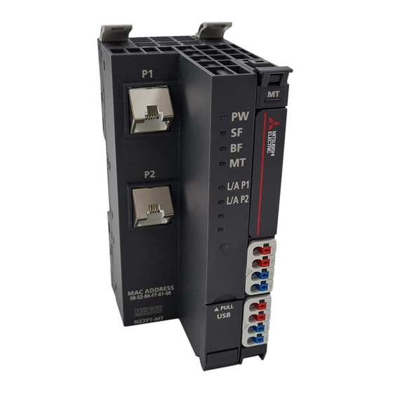
Page 99: Part Names
Part Names This section describes the LEDs of the NZ2FT-GN. ( Page 94 Coupler Common Part Names) (1)(2)(3)(4)(5)(6)(7)(8) (10) (10) Name Description PW LED Displays the power supply status of the NZ2FT-GN. On in green: Power-on Flashing in green: Initializing the NZ2FT-GN Off: Power-off SF LED Displays the status of the NZ2FT-GN. -
Page 100: Ip Address Setting Switch
Name Description USB port and IP address A cover for the USB port and IP address setting switch setting switch cover • USB port: To use the Web server, open this cover and connect a USB cable. • IP address setting switch: Set the fourth octet of the IP address. ( Page 98 IP address setting switch) When not in use, close this cover to prevent entrance of foreign material such as dust. -
Page 101: Performance Specifications
Performance Specifications This section describes the performance specifications of the NZ2FT-GN. ( Page 30 General Specifications). Item Specifications Connection 2RJ45 Network CC-Link IE TSN Station type Remote station Authentication Class Authentication Class B device Number of connectable stations per master station 20 stations maximum Input data size RX: 1024 points maximum... -
Page 102: Functions
Functions This section describes the functions of the NZ2FT-GN. Function list Item Description Reference Fieldbus communication The CC-Link IE TSN communicates with the master station as follows. Page 101 Cyclic transmission • Periodic communication: Cyclic transmission Page 101 Communications • Communication at any time: Communication using the SLMP using the SLMP IP address setting switch settings Set the 4th octet of the IP address with the IP address setting switch. -
Page 103: Cyclic Transmission
Troubleshooting Item Description Reference LED indication The status of the NZ2FT-GN is displayed in LED. Page 97 Part Names Page 123 Checking with LEDs CC-Link IE TSN/CC-Link IE Field Use GX Works3 to check the status of the CC-Link IE TSN system and for any Page 126 CC-Link IE TSN/ diagnostics errors that occurred in the NZ2FT-GN. -
Page 104: Ip Address Duplication Detection
IP address duplication detection When adding NZ2FT-GN to the network, if there are stations with the same IP address on the network, the added NZ2FT-GN will detect duplicate IP addresses. (RAS MELSEC iQ-R CC-Link IE TSN User's Manual (Application)) The NZ2FT-GN checks if another station with the same IP address as its own station exists in the network when P1 or P2 links up. -
Page 105: Output Value Setting For Fieldbus Error
Output value setting for fieldbus error Set the output value of the I/O module for each case, such as when the CPU module status of the master station changes or a fieldbus error occurs. The output value changes depending on the following five settings. ... - Page 106 NZ2FT-GN parameter "Output behaviour on fieldbus error" setting Status of master station (RJ71GN11- 0: All outputs off 1: Enable substitute value (A substitute 2: Hold last value NZ2FT-GN RY refresh target: other (All outputs are value is output.) (The last output than CPU module device Y turned off.)
-
Page 107: Checking Warning Output (Process Alarm)
Checking warning output (Process alarm) Checks whether Process alarm has occurred from the I/O module corresponding to the warning output, and reads Process alarm data of the content. The I/O modules that support the alarm output and their details are as follows. •... -
Page 108: Procedures Before Operation
Procedures Before Operation IP address setting Set the IP address of the NZ2FT-GN. ( Page 98 IP address setting switch) Installation Attach the NZ2FT system to the DIN rail and install it in a suitable environment. ( Page 36 Installation Environment and Installation Position of Module, Page 38 Installation) Wiring Connect the power cable and Ethernet cable to the NZ2FT-GN. -
Page 109: Parameter Setting
Parameter Setting Register the CC-Link IE TSN profile and set the parameters of the RJ71GN11-T2, NZ2FT-GN, and I/O module. Use the following window of GX Works3 of the master station or the Web server. Parameter setting content Relevant product Reference Master station RJ71GN11-T2 Page 107 Settings by GX Works3... - Page 110 ■"CC-Link IE TSN Configuration" window Open the "CC-Link IE TSN Configuration" window. [Navigation window] [Parameter] [Module Information] [RJ71GN11-T2] [Basic Settings] [Network Configuration Settings] Select NZ2FT-GN from "Module List" and drag and drop it onto the network map to set the network configuration. Set "RX Setting", "RY Setting", "RWr Setting", and "RWw Setting"...
-
Page 111: Nz2Ft-Gn And I/O Module Setting
NZ2FT-GN and I/O module setting Set these settings on the Web server or GX Works3 of the master station. Setting by the Web server Set the parameters of the NZ2FT-GN and I/O module on the Web server. ( Page 112 Parameter list) Turn off the master station and configure the settings while communications are not being performed with the master station. - Page 112 ■"Extension Module Configuration" window Open the "CC-Link IE TSN Configuration" window. [Navigation window] [Parameter] [Module Information] [RJ71GN11-T2] [Basic Settings] [CC-Link IE TSN Configuration] Open the "Extension Module Configuration" window. "CC-Link IE TSN Configuration" window Right click on the NZ2FT-GN icon [Open System Configuration] [Open Extension Module Configuration] Select an I/O module from the "Module List"...
- Page 113 ■"Parameter of Slave Station" window (I/O module) Open the "Parameter of Slave Station" window. The operation is the same as the parameter setting of NZ2FT-GN. ( Page 109 "Parameter of Slave Station" window (NZ2FT-GN)) "Extension Module Configuration" window Right-click on the icon for each I/O module [Parameter of Slave Station] When "Parameter write"...
-
Page 114: Parameter List
Parameter list These parameters can be set in the NZ2FT-GN from the Web server or GX Works3 of the master station. : Can be set, : Cannot be set Item Description Setting range Default server Works3 IP address Set the IP address of the USB port. -
Page 115: Access To Process Data
Access to Process Data This section describes the cyclic transmission data of the NZ2FT-GN, including Process data (I/O module input/output data). Data configuration Process data and Status word are placed in the link devices RX, RY, RWr, and RWw, and are stored in the CPU module device of the master station for each NZ2FT-GN station number by cyclic transmission. - Page 116 Master Station Link Item Data size Description station number device CPU module System area 4 words device W Process data Variable length Word output data for the I/O module with station number 1 (In order of (word) proximity to the NZ2FT-GN) ...
-
Page 117: Allocation Of Master Station Cpu Module To Device
Allocation of master station CPU module to device The following system configuration describes the allocation of the master station CPU module device using the RJ71GN11-T2 and the data structure of Process data of the NZ2FT-GN. NZ2FT-GN RJ71GN11-T2 (1) (2) (3) (4) (5) (6) (7) (8) (9)(10)(11)(12)(13) (1) NZ2FTS4-4DE (2) NZ2FTS4-4TE (3) NZ2FTS3-8DE... - Page 118 Master station CPU module NZ2FT-GN Device Station I/O module name Process data number W100 to W103 System area (4 words) RWw0 to RWw3 W104 to W107 NZ2FTS-60DA4 RWw4 to RWw7 W108 to W115 NZ2FTS-D62P2 RWw8 to RWw15 • Process data of I/O modules can also be checked from the Web server. ( Page 72 "Process data"). •...
-
Page 119: Program Example
Program Example Precautions for programming For cyclic transmission, configure an interlock program. The following shows an example example of an interlock program. Classification Label name Description Device Module label GN11_1.bSts_DataLinkError Data link error status of own station SB0049 GN11_1.bnSts_DataLinkError_Station[1] Data link status of each station (station SW00B0.0 number 1) 7 NZ2FT-GN... -
Page 120: Example Using The Nz2Fts-60Ad4
Example using the NZ2FTS-60AD4 The following example is for a program to read AI values that are obtained from A/D conversion performed on AI 0 (Channel 0) to AI 3 (Channel 3) of the analog input module. System configuration NZ2FT-GN RJ71GN11-T2 Item Model... - Page 121 Click the [Setting Change] button and set to use the module label. Set the RJ71GN11-T2 as follows. [Navigation window] [Parameter] [Module Information] Right-click [Add New Module] Click the [OK] button to add a module label of the RJ71GN11-T2. The following window will be displayed.
- Page 122 Set the network configuration of the RJ71GN11-T2 and NZ2FT-GN on the "CC-Link IE TSN Configuration" window. [Navigation window] [Parameter] [Module Information] [NZ2FT-GN] [Basic Settings] [Network Configuration Settings] Set the NZ2FT-GN on the "Parameter of Slave Station" window. "CC-Link IE TSN Configuration"...
- Page 123 Set the configuration of the NZ2FT-GN and NZ2FTS-60AD4 on the "Extension Module Configuration" window. "CC-Link IE TSN Configuration" window Right click on the NZ2FT-GN icon [Open System Configuration] [Open Extension Module Configuration] Set the NZ2FTS-60AD4 on the "Parameter of Slave Station" window. ( Page 484 Parameter settings) "Extension Module Configuration"...
- Page 124 Write the set parameters to the master station CPU module, and reset or power off and on the CPU module. [Online] [Write to PLC] Device/label to be used Device Description D1000 Cyclic transmission D1001 D1002 D1003 GN11_1.bSts_DataLinkError Data link error status of own station GN11_1.bnSts_DataLinkError_Station[1] Data link status of each station X1000 to X101F...
-
Page 125: Troubleshooting
Troubleshooting This section describes troubleshooting of the NZ2FT-GN. If troubleshooting does not solve the problem, acquire the service file, and please consult your local Mitsubishi representative. ( Page 88 Acquisition of the service file) Checking with LEDs When the PW LED turns off Check the following items in order from the top. - Page 126 When the BF LED turns on in red Check the following items in order from the top. Item Action Are the Ethernet cables between the master station, hub, NZ2FT- Push in the Ethernet cable of each connection section until it clicks. GN (or between the master station and NZ2FT-GN directly connected) inserted as far as they will go? Has the Ethernet cable been disconnected?
- Page 127 When the D LINK LED is flashing in green Check the following items in order from the top. Item Action Is the target NZ2FT-GN set as the reserved station in the master In the network configuration setting of the master station, set "No Setting" for "Reserved/ station setting? Error Invalid Station".
-
Page 128: Cc-Link Ie Tsn/Cc-Link Ie Field Diagnostics
CC-Link IE TSN/CC-Link IE Field diagnostics Use GX Works3 to check the status of the CC-Link IE TSN system and for any errors that occurred in the NZ2FT-GN. (Checking the network status MELSEC iQ-R CC-Link IE TSN User's Manual (Application)) Item Description Network map monitor... - Page 129 Follow the instructions on the window to display the "Error History" window. Item Description Error History Reads the error history held inside the NZ2FT-GN. In the error history, up to 16 errors are recorded in the order of new occurrence. If the List number of errors exceeds 16, the oldest errors are deleted in order.
-
Page 130: Confirmation By Status Information (Status Word)
Confirmation by status information (Status word) There are two types of data that indicate the status of the NZ2FT-GN: Status word1 and Status word2. ( Page 113 Access to Process Data) Data configuration Status word1 is stored in Process data (RX(n~n+3)) of each station. Status word2 is stored in Process data (RWr(n+3)) of each station. -
Page 131: Troubleshooting By Symptom
Troubleshooting by symptom Cannot communicate with the master station Check the following item. Item Action Are the LINK P1 LED and LINK P2 LED on? If they are off, perform troubleshooting. Also, check other LEDs. ( Page 123 Checking with LEDs) Is the BF LED off? If it is not turned off, perform troubleshooting. - Page 132 Error Error Error name Error description and Action code type cause D80DH Minor Voltage UOUT error The external power supply Set the voltage of the output power supply (24VDC) within the range of voltage for output is abnormal. performance specifications. D80EH Moderate Voltage UIN error...
-
Page 133: Chapter 8 Nz2Ft-Bt
NZ2FT-BT This chapter describes the details of the CC-Link compatible coupler. CC-Link Configuration A CC-Link system is configured with a master station (1), remote I/O station (2), remote device station (3), intelligent device station (4), local station (5), and terminating resistor (6). The NZ2FT system using the NZ2FT-BT supports CC-Link Ver.1.10 and Ver.2.00 and operates as a remote device station. -
Page 134: Part Names
Part Names This section describes the LEDs of the NZ2FT-BT. ( Page 94 Coupler Common Part Names) (1)(2)(3)(4)(5)(6)(7)(8) (10) Name Description PW LED Displays the power supply status of the NZ2FT-BT. On in green: Power-on Off: Power-off SF LED Displays the status of the NZ2FT-BT. On in red: Error (... -
Page 135: Rotary Switch
Name Description BC LED Displays the transmission speed auto-tracking status. ( Page 137 Transmission speed auto-tracking) Flashing in red/green (every 0.5 seconds): Transmission speed auto-tracking in progress On in green: Transmission speed auto-tracking complete On in red: Fieldbus error Off: Power-off or station number error Rotary switch Set the CC-Link station number. -
Page 136: Connector
Connector This section describes the CC-Link interface connector. The following figure shows the wiring to the terminal block. Connect a Ver.1.10-compatible CC-Link dedicated cable as shown below. Ver.1.10-compatible CC-Link dedicated cable Terminal to connect DA line (blue) DB line (white) DG line (yellow) Shield wire •... -
Page 137: Performance Specifications
Performance Specifications This section describes the performance specifications of the NZ2FT-BT. ( Page 30 General Specifications). Item Specifications Connection Socket for 5-pole PCB plug-in connector (screw connection) Network CC-Link Supported version of CC-Link Ver.1.11, Ver.2.00 Station type Remote device station Number of occupied stations Ver.1.11: 2 to 4 stations, Ver.2.00: 1 to 4 stations Number of connectable stations per master station... -
Page 138: Functions
Functions This section describes the functions of the NZ2FT-BT. Function list Item Description Reference Fieldbus communication The CC-Link communicates with the master module as follows. • Periodic communication: Cyclic transmission • Communication at any time: Dedicated instruction RDMSG Station number setting Set the station number by two rotary switches. -
Page 139: Transmission Speed Auto-Tracking
Transmission speed auto-tracking The transmission speed set by the master station is automatically followed, and the NZ2FT-BT has the same transmission speed. Set the NZ2FT-BT parameter "Power up baud rate" to "Auto baud" (default). ( Page 145 Parameter list) The conditions under which transmission speed auto-tracking operates are as follows. It takes about 5 seconds for the transmission speed to be confirmed. -
Page 140: Output Value Setting For Fieldbus Error
Output value setting for fieldbus error Set the output value of the I/O module for each case, such as when the CPU module status of the master station changes or a fieldbus error occurs. The output value changes depending on the following five settings. ... - Page 141 Status of master station (RJ61BT11/ NZ2FT-BT parameter "Output behaviour on fieldbus error" setting QJ61BT11N/FX5-CCL-MS) 0: All outputs off 1: Enable substitute value (A substitute 2: Hold last value NZ2FT-BT RY refresh target: other (All outputs are value is output.) (The last output than CPU module device Y turned off.)
-
Page 142: Checking Warning Output (Process Alarm)
Checking warning output (Process alarm) Check whether Process alarm has occurred from the I/O module corresponding to the warning output, and read the Process alarm data of the content. The I/O modules that support the alarm output and their details are as follows. •... - Page 143 If the second Process alarm is detected on the same channel of the same I/O module before reading Process alarm data, the second Process alarm data will not be stored correctly. If Process alarm is detected, read Process alarm data. 8 NZ2FT-BT 8.4 Functions...
-
Page 144: Procedures Before Operation
Procedures Before Operation Station number setting Set the station number of the NZ2FT-BT. ( Page 133 Rotary switch) Installation Attach the NZ2FT system to the DIN rail and install it in a suitable environment. ( Page 36 Installation Environment and Installation Position of Module, Page 38 Installation) Wiring Connect the power cable and CC-Link cable to the NZ2FT-BT. -
Page 145: Parameter Setting
Parameter Setting Register the CC-Link profile and set the parameters of the CC-Link master module, NZ2FT-BT, and I/O module. Use the software package of the master station or the Web server. For details on parameter settings of each master module, refer to the following. •... -
Page 146: Nz2Ft-Bt And I/O Module Setting
NZ2FT-BT and I/O module setting Set these settings on the Web server or GX Works3 of the master station. Setting by the Web server Set the parameters of the NZ2FT-BT and I/O module on the Web server. ( Page 145 Parameter list) Turn off the master station and configure the settings while communications are not being performed with the master station. -
Page 147: Parameter List
Parameter list This parameter can be set in the NZ2FT-BT from the Web server or GX Works3/GX Works2 of the master station. : Can be set, : Cannot be set Item Description Setting range Default server Works3/2 IP address USB Set the IP address of the USB port. - Page 148 Item Description Setting range Default server Works3/2 Reset Device Set the resetting of the NZ2FT-BT. • no action no action • no action: Not reset • restart • restart: Reset 8 NZ2FT-BT 8.6 Parameter Setting...
-
Page 149: Access To Process Data
Access to Process Data This section describes the cyclic transmission data of the NZ2FT-BT, including Process data (I/O module input/output data). Data configuration Process data and Status word are placed in the link devices RX, RY, RWr, and RWw, and are stored in the CPU module device of the master station for each NZ2FT-BT station number by cyclic transmission. - Page 150 Master Station Link Item Data size Description station number device device System area 4 words Process data Variable length Word output data for the I/O module with station number 1 (In order of (word) proximity to the NZ2FT-BT) ...
-
Page 151: Allocation Of Master Station Cpu Module To Device
Allocation of master station CPU module to device For details on each master module, refer to the following. • RJ61BT11: Communication example between the master station and remote device station ( MELSEC iQ-R CC-Link System Master/Local Module User's Manual (Startup)) •... - Page 152 Master station CPU module NZ2FT-BT Device Station I/O module name Process data number Y1000 to Y100F System area (16 bits) RY0 to RYF Y1010 to Y101F NZ2FTS4-4TE RY10 to RY1F Y1020 to Y102F NZ2FTS2-8TE RY20 to RY2F Y1030 to Y103F NZ2FTS2-8TE RY30 to RY3F Y1040 to Y104F...
-
Page 153: Concept Of Data Length
Concept of data length The data length is determined by the following three parameters. • Parameter "Number of occupied stations" • Parameter "Protocol version" • Parameter "Extended-Cyclic-Messaging-Factor" The following describes how to calculate the data length. Calculate the data length for each device according to the system configuration. ( Page 148 Data width used by the I/O module) Mounting module Data length per device... -
Page 154: Number Of I/O Modules That Can Be Mounted Per Station
Number of I/O modules that can be mounted per station For each device, calculate how many I/O modules can be mounted in the NZ2FT-BT of one station. However, the total is up to 64 units. Digital input module Number of mountable modules = (Total data size of Process data - Status word (16 bits) - System area (16 bits)) / Data width of I/O module Parameter "Number Device... - Page 155 High-speed counter / serial communication module Number of mountable modules = (Total data size of Process data - System area (4 words)) / Data width of I/O module Parameter "Number Device Data width of Protocol version / Parameter "Extended-Cyclic-Messaging-Factor" of occupied I/O modules Ver.1.11 Ver.2.00 / 1x...
-
Page 156: Program Example
Program Example Precautions for programming In the CC-Link transmission program, interlock is provided with Data link status of other station (SW0080 to SW0083). The following shows an example of interlocking between two stations. Classification Label name Description Device Module label BT11_1.bnSts_DataLinkError_Other[1] Data link status of other stations SW0080.0... -
Page 157: Example Using The Nz2Fts-60Ad4
Example using the NZ2FTS-60AD4 The following example is for a program to read in the master station AI values that are obtained from A/D conversion performed on AI 0 (Channel 0) to AI 3 (Channel 3) of the analog input module. System configuration NZ2FT-BT RJ61BT11... - Page 158 Master station setting Connect the software package to the master station CPU module and set the parameters. Set the CPU module as follows. [Project] [New] Click the [Setting Change] button and set to use the module label. Set the RJ61BT11 as follows. [Navigation window] ...
- Page 159 Click the [OK] button to add a module label of the RJ61BT11. Set the network configuration as follows. [Navigation window] [Parameter] [Module Information] [RJ61BT11] [Basic Settings] [Network Configuration Settings] Set the link refresh settings as follows. [Navigation window] ...
- Page 160 Remote device station setting Set the parameters of the NZ2FT-BT and NZ2FTS-60AD4. ( Page 144 NZ2FT-BT and I/O module setting) Set the following values for the parameters of the NZ2FTS-60AD4. ( Page 484 Parameter settings) Parameter Setting value AI 0 (Channel 0) AI 1 (Channel 1) AI 2 (Channel 2) AI 3 (Channel 3)
-
Page 161: Example Using The Nz2Fts-60Rd4
Example using the NZ2FTS-60RD4 This program reads Process alarm data when Process alarm occurs in RTD 0 (Channel 0) to RTD 3 (Channel 3) of the temperature input module. System configuration NZ2FT-BT RJ61BT11 Item Model Master station (station number 0) CPU module R04CPU Power supply module... - Page 162 Master station setting The parameter setting method at the master station is the same as that in the example using the NZ2FTS-60AD4. ( Page 156 Master station setting) Remote device station setting Set the parameters of the NZ2FT-BT and NZ2FTS-60RD4. ( Page 144 NZ2FT-BT and I/O module setting) Set the following values for the parameters of the NZ2FTS-60RD4.
- Page 163 8 NZ2FT-BT 8.8 Program Example...
-
Page 164: Troubleshooting
Troubleshooting This section describes troubleshooting of the NZ2FT-BT. If troubleshooting does not solve the problem, acquire the service file, and please consult your local Mitsubishi representative. ( Page 88 Acquisition of the service file) Checking with LEDs This section describes troubleshooting with LEDs of the NZ2FT-BT. ( Page 132 Part Names) When the PW LED turns off Check the following items in order from the top. - Page 165 When the BF LED turns on in red Check the following items in order from the top. Item Action Is the CC-Link cable between the master station Fix the cable firmly by the screw. and the NZ2FT-BT inserted as far as it will go? Has the CC-Link cable been disconnected? Replace the CC-Link cable.
- Page 166 When the RUN LED turns off Check the following items in order from the top. Item Action Is the external power supply (24VDC) wired? Wire the external power supply (24VDC). Is the external power supply (24VDC) turned on? Turn on the external power supply (24VDC). Is the voltage of the external power supply Set the voltage of the external power supply within the range of performance specifications.
-
Page 167: Cc-Link Diagnostics
When the following LEDs turn on in red • Power supply LED • Input power supply LED 3.2 • Output power supply LED 4.2 • Input power supply internal protection circuit LED 3.4 • Output power supply internal protection circuit LED 4.4 Check the following item. -
Page 168: Confirmation By Status Information (Status Word)
Confirmation by status information (Status word) There are two types of data that indicate the status of the NZ2FT-BT: Status word1 and Status word2. ( Page 147 Data configuration) Data configuration Status word1 is stored in Process data (RX(n~n+3)) of each station. Status word2 is stored in Process data (RWr(n+3)) of each station. -
Page 169: Troubleshooting By Symptom
How to check Status word ■GX Works3 Read the corresponding device W of "Status word2" in "Device/Buffer Memory Batch Monitor". ( Page 149 Allocation of master station CPU module to device) ■Web server "Status word2" is displayed in decimal in "Coupler status" of "General information" of the NZ2FT-BT. ( Page 71 "Component view") Troubleshooting by symptom Cannot communicate with the master station... -
Page 170: Chapter 9 Nz2Ft-Pn
NZ2FT-PN This chapter describes the details of the PROFINET compatible coupler. PROFINET Configuration PROFINET consists of an RJ71PN92 (1) and IO devices (2). The NZ2FT system using the NZ2FT-PN operates as an IO device. Corresponding master module and software package The master module corresponding to the NZ2FT-PN and the software package corresponding to the master module are shown. -
Page 171: Part Names
Part Names This section describes the LEDs of the NZ2FT-PN. ( Page 94 Coupler Common Part Names) (1)(2)(3)(4)(5)(6)(7)(8) (10) Name Description PW LED Indicates the status of the module power supply. On in green: Power-on Off: Power-off SF LED Indicates the module status. On in red: Error (... -
Page 172: Performance Specifications
Performance Specifications This section describes the performance specifications of the NZ2FT-PN. ( Page 30 General Specifications) Item Specifications Connection 2RJ45 Network PROFINET IO (IRT, RT) Number of NZ2FT-PN connections per RJ71PN92 20 stations maximum Input data size 512 bytes maximum Output data size 512 bytes maximum Parameter data... -
Page 173: Functions
Functions This section describes the functions of the NZ2FT-PN. Function list Item Description Reference Fieldbus communication The PROFINET IO protocol communicates with the RJ71PN92 as follows. Page 171 Service interface • Fixed cycle communication: I/O data communication function • Communication at any time: Service interface function Parameter setting Set the parameters of the NZ2FT-PN and IO module with GX Configurator-PN and Page 200 Parameter Setting... - Page 174 Web server functions The following are the functions operated by the Web server. Set the communication parameters of the NZ2FT-PN and I/O module in the RJ71PN92 software package. ( Page 200 GX Configurator-PN setting procedure) Item Description Reference Web server connection Connect from a personal computer via the USB port or Ethernet port.
-
Page 175: Output Value Setting For Fieldbus Error
Output value setting for fieldbus error Set the output value of the I/O module for each case, such as when the CPU module status of the master station changes or a fieldbus error occurs. The output value changes depending on the following two settings. •... -
Page 176: Option Handling
Option handling Set each I/O module to stop/operate while the NZ2FT system is operating. If I/O control is not to be performed for a specific I/O module for a certain period of time, set that I/O module to stop. By doing so, an error resulting from disconnecting the electronic unit part can be suppressed. - Page 177 ■Operation of each module Module Location of Operation description operation After disconnecting the electronic unit part After writing Dataset and set to be stopped NZ2FT-PN SF LED On in red (configuration error) BF LED Flashing in red (configuration error) Status word Bit 6: 1 Bit 6: 0 I/O-Configuration error (There is a difference between the...
- Page 178 Operation until restart The following describes the operations to be performed to restart the I/O module in stopped state, including those to be performed after the electronic unit part is connected and after Dataset is written and the operation is set. ( Page 57 Mounting electronic unit part) The "Overview"...
- Page 179 ■Operation of each module Module Location of Operation description operation After disconnecting the electronic unit part After writing Dataset and set to be stopped NZ2FT-PN SF LED On in red (configuration error) BF LED Flashing in red (configuration error) Status word Bit 6: 1 Bit 6: 0 I/O-Configuration error (There is a difference between the...
- Page 180 Dataset The following is the configuration information for sorting the I/O modules to be set to stop/operate. Address Data Description Setting value length 1 byte Dataset length Number of fixed areas (4 bytes) + number of connected I/O modules 1 byte ...
- Page 181 Stop procedure and setting example The following case is described. • NZ2FT-PN IO device ID: 1 • Buffer memory address: Service request area 1 (C350H to CB77H) of the service interface function Precautions ■Reverse procedure Disconnect the electronic unit part before writing Dataset. Conversely, if the electronic unit part is disconnected after Dataset is written, the SF LED turns on in red, the BF LED flashes in red, and the I/O module will continue to operate.
- Page 182 Write Dataset to the NZ2FT-PN based on the setting value in procedure 2. To write Dataset, use the service interface function "Acyclic communication - Explicit write data record". ( MELSEC iQ-R PROFINET IO Controller Module User's Manual (Application)) Buffer Item Setting Description memory...
- Page 183 Restart procedure and setting example The following case is described. • NZ2FT-PN IO device ID: 1 • Buffer memory address: Service request area 1 (C350H to CB77H) of the service interface function Precautions ■Installation and Dataset write Connect the electronic unit part before writing Dataset. Conversely, if the electronic unit part is connected after Dataset is written, the SF LED turns on in red, the BF LED flashes in red, and the I/O module will not restart the operation.
- Page 184 Option handling program example The following shows an example of a program that executes Option handling for general purposes. Set the slot number (1 to 64) whose operation is to be stopped or restarted to D100, and turn on M10 to read, create, and write Dataset.
- Page 185 ■Program example of Dataset read 9 NZ2FT-PN 9.4 Functions...
- Page 186 9 NZ2FT-PN 9.4 Functions...
- Page 187 ■Program example of Dataset creation 9 NZ2FT-PN 9.4 Functions...
- Page 188 9 NZ2FT-PN 9.4 Functions...
- Page 189 9 NZ2FT-PN 9.4 Functions...
- Page 190 9 NZ2FT-PN 9.4 Functions...
- Page 191 ■Program example of Dataset write 9 NZ2FT-PN 9.4 Functions...
-
Page 192: Acyclic Communication - Implicit Read Data Record
Acyclic communication - Implicit read data record The NZ2FT-PN specified by the IP address responds to the service request (Record data read) from the RJ71PN92 and sends the service response. The data that can be read is as follows. • Dataset used in Option handling •... - Page 193 ■Details of read/write data Classification Item Setting value when reading/writing Dataset used in Option handling Header 00000000H SlotNumber 0000H SubslotNumber 0001H Index 00C4H Data Data If Dataset is not written, addresses 0 to 3 of Dataset are read. ( Page 178 Dataset) 9 NZ2FT-PN 9.4 Functions...
-
Page 194: Acyclic Communication - Explicit Write Data Record
Acyclic communication - Explicit write data record The NZ2FT-PN specified by the IO device ID responds to the service request (Record data write) from the RJ71PN92 and sends the service response. The data that can be written is as follows. •... -
Page 195: Acyclic Communication - Explicit Read Data Record
Acyclic communication - Explicit read data record The NZ2FT-PN specified by the IO device ID responds to the service request (Record data read) from the RJ71PN92 and sends the service response. The data that can be read is as follows. •... -
Page 196: Alarm Request
Alarm request This function reads the alarm information accumulated in the RJ71PN92 to the CPU module. To execute the alarm request, set the corresponding IO device to manual alarm processing in the 'IO device alarm management area' (Un\G17025 to Un\G17032) of the RJ71PN92 in advance. (Alarm acquisition function MELSEC iQ-R PROFINET IO Controller Module User's Manual (Application)) If the alarm request is executed in a state where no alarm has occurred, the error response is sent from the RJ71PN92 to the CPU module. - Page 197 Service response format The following describes the response format for alarm requests. It is sent from the RJ71PN92 to the CPU module and stored in the service response area. Classification Item Size Description Stored value Header RequestID 4 bytes RequestID set in the service request format is stored.
-
Page 198: Alarm Ack
Alarm ACK In response to the alarm ACK from the RJ71PN92, the alarm generated on the NZ2FT-PN is cleared and the alarm ACK response is sent to the RJ71PN92. Also, alarm information accumulated in the RJ71PN92 is cleared. To execute the alarm ACK, set the corresponding IO device ID (station number) to manual alarm processing in the 'IO device alarm management area' (Un\G17025 to Un\G17032) of the RJ71PN92 in advance. - Page 199 Alarm ACK response format The following describes the response format for the alarm ACK. It is sent from the NZ2FT-PN to RJ71PN92 and stored in the service response area. The alarm ACK service does not have a stored value unique to the NZ2FT. Classification Item Size...
-
Page 200: Alarm Log Acquisition
Alarm log acquisition This function reads the alarm log accumulated in the RJ71PN92 to the CPU module. If multiple alarms occur in the same NZ2FT-PN, acquire the alarm log multiple times also. Service request format The following describes the request format of the alarm log acquisition from the CPU module to RJ71PN92. Set the following values in the service request area. -
Page 201: Procedures Before Operation
Procedures Before Operation Installation Attach the NZ2FT system to the DIN rail and install it in a suitable environment. ( Page 36 Installation Environment and Installation Position of Module, Page 38 Installation) Wiring Connect the power cable and Ethernet cable to the NZ2FT-PN. ( Page 45 Wiring of power cable and I/O cable, Page 46 Ethernet cable) Connect the I/O cables to the I/O module. -
Page 202: Parameter Setting
Parameter Setting The parameters for the RJ71PN92 and IO device (NZ2FT-PN and I/O module) are set using GX Works3 and GX Configurator- PN. (Parameter setting procedure MELSEC iQ-R PROFINET IO Controller Module User's Manual (Application)) GX Works3 setting The parameters of the RJ71PN92 (other than communication parameters) are set in GX Works3. ( Page 215 GX Works3 setting) For use with GX Configurator-PN, set the IP address of the RJ71PN92 in advance and write it to the CPU module. - Page 203 Select "Add all the GSDML from the Directory" with the radio button, click the [Browse] button, specify the GSDML folder, and click the [Next] button. The result of the GSDML file addition to "Device Library" is displayed. Click the [Next] button. Click the [Finish] button on the displayed window to close the "GSDML Management"...
- Page 204 Device Name setting In PROFINET, set Device Name corresponding to the station number on the "Devices on the Network" window. (Window layout MELSEC iQ-R PROFINET IO Controller Module User's Manual (Application)) [Network Detection] tab Right click on "Network" [Network] [Online Action] When the "Devices on the Network"...
- Page 205 Network configuration setting Set the NZ2FT-PN and I/O module in the "RJ71PN92" tree of the network configuration setting. (Window layout MELSEC iQ-R PROFINET IO Controller Module User's Manual (Application)) ■NZ2FT-PN On the [Device Library] tab, right-click either "NZ2FT-PN Profinet Device" or "NZ2FT-PN Profinet Device with Status Word"...
- Page 206 Item Description Device Name Set a name for each IO device to be used in GX Configurator-PN. The same name cannot be set for multiple IO devices. Use Designation a unique string such as NZ2FT_PN_001. (Default: NZ2FT_PN) Number Select the IO device ID. IO device IDs are numbers used by the RJ71PN92 to manage IO devices. They are used to distinguish IO devices by specifying the buffer memory bits.
- Page 207 ■I/O module Open the [Module Configuration] tab on the "NZ2FT-PN Profinet Device" window. Select the I/O module installed in the NZ2FT-PN from "Available Modules" and click the [] button. The selected I/O module is added to "Configured Modules". When the I/O module is deleted, the segment becomes [empty].
- Page 208 ■RJ71PN92 In the [Parameters] tab of the "NZ2FT-PN Profinet Device" window, set "Refresh Period", "Device Data Order", and "Watchdog Factor". Click the [OK] button to register the NZ2FT-PN and I/O module in "Module Configuration" in the "RJ71PN92" tree of the network configuration setting.
- Page 209 Slave parameter setting Set the parameters of the NZ2FT-PN and I/O module in the RJ71PN92. After setting, when the RJ71PN92 and NZ2FT-PN start I/O data communication, the parameters are reflected in the NZ2FT- PN and I/O module. ■NZ2FT-PN Set the parameters of the NZ2FT-PN with the software package of the RJ71PN92. Parameter item Software package Setting location...
- Page 210 ■I/O module In "Module Configuration" in the "RJ71PN92" tree of the network configuration setting, right-click "000 NZ2FT-PN Profinet Device" and select "Properties". The "NZ2FT-PN Profinet Device" window opens. Select the parameter to be set from the [Parameters] tab and click the [OK] button.
-
Page 211: Parameter List
Parameter list The following shows the parameters that can be set for the NZ2FT-PN. Web server The following are parameters to be set on the Web server. ( Page 74 Parameter setting) Parameters other than the following are set by GX Configurator-PN of the RJ71PN92, so do not set them by the Web server. Item Description Setting range... - Page 212 Item Description Setting range Default Lock force mode Set whether to enable or disable to switch to the Force mode. ( Page 207 Slave • Force mode unlocked Force mode parameter setting) • Force mode locked unlocked • Force mode unlocked: Switch to the Force mode is enabled. •...
-
Page 213: Access To Process Data
Access to Process Data The I/O data of the I/O module is stored in Process data of the NZ2FT-PN and data communication is performed with the RJ71PN92. Data configuration For each IO device, Process data and Status word are placed in Output data and Input data. Status word is data indicating the status of the NZ2FT-PN. -
Page 214: Assignment Of The Rj71Pn92 To The Buffer Memory
Data width used by the I/O module The following table shows the data width used by each I/O module in the NZ2FT-PN during I/O data communication (constant periodic communications). I/O module Process data Reference Input Output NZ2FTS4-4DE 16 bits Page 420 Process data NZ2FTS3-8DE 16 bits... - Page 215 The following system configuration describes the assignment of the RJ71PN92 to the buffer memory and the data structure of Process data of the NZ2FT-PN. NZ2FT-PN RJ71PN92 (1) (2) (3) (4) (5) (6) (7) (8) (9)(10)(11)(12)(13) (1) NZ2FTS4-4DE (2) NZ2FTS4-4TE (3) NZ2FTS3-8DE (4) NZ2FTS2-8TE (5) NZ2FTS3-8DE (6) NZ2FTS2-8TE...
-
Page 216: Program Example
Program Example Precautions for programming In PROFINET transmission programs, interlock is provided in a communication program with the following device. • I/O data communication function start command (M1000) • Service interface execution signal (M2000) When the I/O data communication function start command (M1000) of the NZ2FT-PN turns on, I/O data communication is executed. - Page 217 Device assignment The following figure shows the device allocation for I/O data communication. ( Page 212 Data width used by the I/O module) Master station Slave station CPU module RJ71PN92 NZ2FT-PN NZ2FTS-60AD4 Buffer memory Process data Input data (input data area) Byte Content Byte...
- Page 218 Set the RJ71PN92 as follows. [Navigation window] [Parameter] [Module Information] Right-click [Add New Module] Set the items in "Basic Setting" as follows. [Navigation window] [Parameter] [Module Information] [RJ71PN92] [Module Parameter] [Basic Setting] 9 NZ2FT-PN 9.8 Program Example...
- Page 219 GX Configurator-PN setting The parameters of the NZ2FT-PN and NZ2FTS-60AD4 are set with GX Configurator-PN of the master station. ( Page 200 GX Configurator-PN setting procedure) Start GX Configurator-PN from GX Works3. [Navigation window] [Parameter] [Module Information] [RJ71PN92] [PROFINET Module Setting] Set Device Name of the RJ71PN92 to "nz2ft-pn".
- Page 220 On the [Module Configuration] tab of the "NZ2FT-PN Profinet Device" window, select the I/O module from "Available Modules" and click the [] button. Set the parameters of the NZ2FTS-60AD4 as follows. ( Page 207 Slave parameter setting) Parameter Setting value AI 0 (Channel 0) AI 1 (Channel 1) AI 2 (Channel 2)
- Page 221 Program example ■Device/label to be used Device Description Module Ready U0\G17000.0 I/O data communication start request U0\G17118.0 Parameter setting status U0\G17119.0 Module error U0\G17153.1 IO device communication status U0\G17161.1 IO device error D1000 I/O data communication D1001 D1002 D1003 D1010 IO device error details ■Program example of I/O data communication function Changing the CPU module status STOP to RUN executes I/O data communication.
-
Page 222: Troubleshooting
Troubleshooting This section describes troubleshooting of the NZ2FT-PN. If troubleshooting does not solve the problem, acquire the service file, and please consult your local Mitsubishi representative. ( Page 88 Acquisition of the service file) Checking with LEDs The status of the NZ2FT-PN is displayed in LED. ( Page 169 Part Names) When the PW LED turns off Check the following items in order from the top. - Page 223 When the BF LED turns on in red Check the following items in order from the top. Item Action Is the Ethernet cable between the RJ71PN92, Push in the Ethernet cable of each connection section until it clicks. hub, and NZ2FT-PN inserted as far as it will go? Has the Ethernet cable been disconnected? Replace the Ethernet cable.
- Page 224 When the following LEDs turn on in red • Power supply LED • Input power supply LED 3.2 • Output power supply LED 4.2 • Input power supply internal protection circuit LED 3.4 • Output power supply internal protection circuit LED 4.4 Check the following item.
-
Page 225: Confirmation By Status Information (Status Word)
Confirmation by status information (Status word) Check the Status word indicating the status of the NZ2FT-PN with the RJ71PN92 or Web server. ( Page 211 Input data) Data configuration The Status word is added to the start of Input data of each IO device by the GX Configurator-PN setting. ( Page 201 Device Library) Item Description... - Page 226 How to check Status word ■GX Works3 Check Un\G36000 of "Status word" on the monitor. ( Page 212 Assignment of the RJ71PN92 to the buffer memory) ■Web server It is displayed in decimal in "Coupler status" of "General information" of the NZ2FT-PN. ( Page 71 "Component view") 9 NZ2FT-PN 9.9 Troubleshooting...
-
Page 227: Troubleshooting By Symptom
Troubleshooting by symptom Cannot communicate with the RJ71PN92 Check the following items. Item Action Are the LINK1 LED and LINK2 LED of the NZ2FT- If it is not turned on, perform troubleshooting. Also, check other LEDs. ( Page 221 When the LINK1 PN on? LED and LINK2 LED turn off) Is the BF LED on the NZ2FT-PN off? -
Page 228: Chapter 10 Nz2Ft-Pbv
NZ2FT-PBV This chapter describes the details of the PROFIBUS-DP compatible coupler. 10.1 PROFIBUS-DP configuration PROFIBUS-DP consists of a DP-Master (1), DP-Slave (2), and terminating resistor (3). The NZ2FT system using the NZ2FT-PBV operates as a DP-Slave. Corresponding master module and software package The master module corresponding to the NZ2FT-PBV and the software package corresponding to each master module are shown. -
Page 229: Part Names
10.2 Part Names This section describes the LEDs of the NZ2FT-PBV. ( Page 94 Coupler Common Part Names) (1)(2)(3)(4) Name Description PW LED Indicates the status of the module power supply. On in green: Power-on Off: Power-off SF LED Indicates the module status. On in red: Error (... -
Page 230: Rotary Switch
Rotary switch Use the rotary switch to set the FDL address of the NZ2FT-PBV. When setting the FDL address, turn off the NZ2FT-PBV. Rotary switch H indicates the 16s place in 2-digit hexadecimal, and rotary switch L indicates the 1s place in 2-digit hexadecimal. -
Page 231: Profibus Interface
PROFIBUS interface Use a PROFIBUS compatible cable. ( Page 42 Wiring products for NZ2FT-PBV) Pin layout Name Application SHIELD Shield, protection ground Data B Receive/send data-P DGND Data ground VP +5V Voltage+ Data A Receive/send data-N ... -
Page 232: Performance Specifications
10.3 Performance Specifications This section describes the performance specifications of the NZ2FT-PBV. ( Page 30 General Specifications) Item Specifications Connection D-Sub9 pin connector Network PROFIBUS-DP V0, PROFIBUS DP-V1 Number of connectable stations per DP-Master 20 stations maximum Input data width 244 bytes maximum Output data width Parameter data... -
Page 233: Functions
10.4 Functions This section describes the functions of the NZ2FT-PBV. Function list Item Description Reference Fieldbus communication The PROFIBUS-DP protocol is used to communicate with the master module as Page 226 PROFIBUS-DP follows. configuration • Fixed cycle communication: I/O data communication •... -
Page 234: Dp Alarm Mode Switching
DP alarm mode switching This function switches the DP alarm mode of PROFIBUS-DP between "V0" and "V1". Set in the parameter "DP alarm mode" of the software package of the master module. • When "V0" is set, the alarm trigger is set with the parameter. The parameter "Process alarm" can be set to enable (default) or disable, and is valid only in V0 mode. -
Page 235: Output Value Setting For Fieldbus Error
Output value setting for fieldbus error Set the output value of the I/O module for each case, such as when the CPU module status of the DP-Master changes or a fieldbus error occurs. The output value changes depending on the following two settings. •... -
Page 236: Checking Warning Output (Process Alarm)
Checking warning output (Process alarm) Check whether Process alarm has occurred from the I/O module corresponding to the warning output, and read Process alarm data of the content. The I/O modules that support the warning output and their details are as follows. •... - Page 237 ■Reading Process alarm data The following describes the example where the master module is the RJ71PB91V. Check if Process alarm has been detected. ( Page 234 Checking for the presence of Process alarm). Use the alarm read request (with ACK) to read Process alarm data. When the alarm read (with ACK) request code and FDL address are set in the buffer memory of the RJ71PB91V and the alarm read request signal (Y18) is turned off and on, Process alarm data of each DP-Slave is stored in the alarm response area.
- Page 238 When alarms are read and Process alarm data is stored in the alarm response area (for the RJ71PB91V) (1) The response code when an alarm read (with ACK) request is completed successfully: A502H (2) FDL address of the DP-Slave (3) Completed status (4) Alarm data length: 4 (5) Process alarm: A511H (6) Mounting position of the I/O module (4th I/O module in the above figure)
-
Page 239: Procedures Before Operation
10.5 Procedures Before Operation FDL address setting Set the FDL address of the NZ2FT-PBV. ( Page 228 Rotary switch) Installation Attach the NZ2FT system to the DIN rail and install it in a suitable environment. ( Page 36 Installation Environment and Installation Position of Module, Page 38 Installation) Wiring Connect the power cables and PROFIBUS cables to the NZ2FT-PBV. -
Page 240: Parameter Setting
10.6 Parameter Setting Set the communication parameters of the master module, NZ2FT-PBV, and I/O module from the software package of the master module. RJ71PB91V and QJ71PB92V setting Start PROFIBUS Configuration Tool or GX Configurator-DP and configure the PROFIBUS-DP communication settings and the parameter settings of the NZ2FT-PBV and I/O module. - Page 241 ■Parameters of the NZ2FT-PBV and I/O module Set the parameters of the NZ2FT-PBV and I/O module on the "Slave Settings" window. [PROFIBUS Network] Right click on NZ2FT-PBV [Slave Settings] Set the FDL address of the NZ2FT-PBV. Enter the FDL address set with the rotary switch of the NZ2FT-PBV for "FDL address" on the "Slave Settings" window. Set the structure of the DP-Slave.
- Page 242 Check "DP V1 support enabled" to use the PROFIBUS-DPV1 function. Precautions • If the set I/O module configuration and the DP-Slave configuration are different, an error occurs on the NZ2FT-PBV and the I/O module. • The PROFIBUS-DPV2 function cannot be used on the NZ2FT-PBV. 10 NZ2FT-PBV 10.6 Parameter Setting...
-
Page 243: Parameter List
Parameter list Set the parameters from the software package of the master module. ( Page 238 Parameter Setting) The following table lists the parameters that can be set to the NZ2FT-PBV. Item Description Setting range Default DP alarm mode Set the alarm mode. ( Page 232 DP alarm mode switching) •... -
Page 244: Access To Process Data
10.7 Access to Process Data Process data is I/O data of the I/O module stored in the NZ2FT-PBV during I/O data communication (constant periodic communications) with the master module. Data configuration Process data consists of Input data and Output data. Item Data size Description... - Page 245 Assignment of the master module to the buffer memory Process data of the NZ2FT-PBV is stored in the following buffer memory addresses of the master module by I/O data communication. Item Buffer memory address Description Input data area (for mode 3) Un\6144 to Un\10239 The area that stores Input data received from each DP-Slave Output data area (for mode 3)
- Page 246 The following system configuration describes the assignment of the RJ71PB91V to the buffer memory and the data structure of Process data of the NZ2FT-PBV. (1) (2) (3) (4) (5) (6) (7) (8) (9) (10) (11) (12) (13) (1) NZ2FTS4-4DE (2) NZ2FTS4-4TE (3) NZ2FTS3-8DE (4) NZ2FTS2-8TE (5) NZ2FTS3-8DE...
- Page 247 Buffer memory Input data NZ2FTS3-8DE NZ2FTS4-4DE Address Station No.1 NZ2FTS1-16DE NZ2FTS3-8DE 1800H NZ2FTS1-16DE Station No.20 (maximum) NZ2FTS-60AD4 NZ2FTS3-8DE NZ2FTS-D62P2 Output data NZ2FTS2-8TE NZ2FTS4-4TE Station No.1 NZ2FTS1-16TE NZ2FTS2-8TE 3800H NZ2FTS1-16TE Station No.20 (maximum) NZ2FTS-60DA4 NZ2FTS2-8TE NZ2FTS-D62P2 ■Input data • Process data of each I/O module is arranged in order of mounting position proximity to the NZ2FT-PBV and with no clearance.
-
Page 248: Program Example Of Nz2Ft-Pbv
10.8 Program Example of NZ2FT-PBV Precautions for programming In NZ2FT-PBV transmission programs, interlock is provided with the following device. • I/O data communication start command (M1000) The following shows an example of interlock being provided in a communication program through the use of I/O data communication start command (M1000). - Page 249 Device assignment The following figure shows the device allocation for I/O data communication. ( Page 243 Assignment of the master module to the buffer memory) Master station Slave station CPU module RJ71PB91V NZ2FT-PBV NZ2FTS-60AD4 Buffer memory Input data Process data Device/label memory (input data area) Byte...
- Page 250 Device used Device Description Data exchange start completed signal Diagnostic information detection signal Communication READY signal Module ready signal Data exchange start request signal D1000 I/O data exchange function D1001 D1002 D1003 FDL address 1 normal communication detection M1000 I/O data exchange start command Program example When data exchange starts, the reading of AI values starts automatically.
-
Page 251: Example Using The Nz2Fts-60Rd4
Example using the NZ2FTS-60RD4 This program reads Process alarm data when Process alarm occurs in RTD 0 (Channel 0) to RTD 3 (Channel 3) of the temperature input module (Resistance Temperature Detector). System configuration NZ2FT-PBV RJ71PB91V Item Model DP-Master (FDL address 0) CPU module R04CPU Power supply module... - Page 252 Parameter Setting Use PROFIBUS Configuration Tool to set the communication parameters of the RJ71PB91V and the parameters of the NZ2FT-PBV and NZ2FTS-60AD4. ( Page 238 RJ71PB91V and QJ71PB92V setting) ■NZ2FT-PBV Set the parameters as shown below. ( Page 241 Parameter list) Item Description DP alarm mode...
- Page 253 Device used Device Description Data exchange start completed signal Communication READY signal Module ready signal Data exchange start request signal D1000 I/O data exchange RTD 0 function D1001 RTD 1 D1002 RTD 2 D1003 RTD 3 FDL address 1 normal communication detection M1000 I/O data exchange start command Alarm acquisition...
- Page 254 Program example When data exchange starts, the reading of RTD values starts automatically. The values of RTD 0 to RTD 3 are stored in D1000 to D1003. Turning on the alarm acquisition request issues an alarm read (with ACK) request. High alarm and Low alarm of RTD 0 to RTD 3 are stored in D2007, and 16 Bit Time stamp is stored in D2008.
-
Page 255: Troubleshooting
10.9 Troubleshooting This section describes troubleshooting of the NZ2FT-PBV. If troubleshooting does not solve the problem, acquire the service file, and please consult your local Mitsubishi representative. ( Page 88 Acquisition of the service file) Checking with LEDs When the PW LED turns off Check the following items in order from the top. - Page 256 When the BF LED turns on in red Check the following items in order from the top. Item Action Is the PROFIBUS cable between the DP-Master The PROFIBUS cable is not connected. Fix the cable firmly by the screw. and NZ2FT-PBV inserted as far as it will go? Has the PROFIBUS cable been disconnected? Replace the PROFIBUS cable.
-
Page 257: Confirmation By Status Information (Standard/Extended Diagnosis)
Confirmation by status information (Standard/Extended Diagnosis) Standard Diagnosis shows the status of the NZ2FT-PBV, and Extended Diagnosis shows the I/O module status and alarm occurrence. Standard/Extended Diagnosis is automatically stored asynchronously in the buffer memory of the master module. Assignment of the master module to the buffer memory The following describes the situation where the master module is the RJ71PB91V. - Page 258 Buffer memory Diagnostic information (4 bytes) Diagnostic information area FDL address 1 Status 3 NZ2FT-PBV FDL address 5A20H Status 1 Status 2 FDL address 20 (maximum) 5B1AH Extended diagnostic information (93 bytes maximum) Extended diagnostic information area 5B20H Latest extended NZ2FT-PBV FDL address diagnostic information Data size (byte length)
- Page 259 For details on the buffer memory of the master module, refer to the following. RJ71PB91V: MELSEC iQ-R PROFIBUS-DP Module User's Manual (Application) QJ71PB92V: PROFIBUS-DP Master Module User's Manual (Details) ■Allocation of Standard Diagnosis Standard Diagnosis of the NZ2FT-PBV is assigned to the diagnostic information area of the buffer memory of the RJ71PB91V as shown below.
- Page 260 Data configuration ■Standard Diagnosis Address Item Description Detected (byte) Status 1 I/O data communication with the NZ2FT-PBV is disabled. DP-Master The NZ2FT-PBV is not ready for I/O data communication. DP-Slave The I/O bytes parameter received from the DP-Master does not match that of the NZ2FT- DP-Slave PBV.
- Page 261 ■Identifier Related Diagnosis Address (byte) Description b0 to b5 Size of Identifier Related Diagnosis (byte length) b6 to b7 1: Identifier Related Diagnosis b0 to b7 The presence or absence of Diagnosis Data is notified from I/O modules at the mounting position 1 to 8. b0 to b7 The presence or absence of Diagnosis Data is notified from I/O modules at the mounting position 9 to 16.
- Page 262 ■Module Status Address (byte) Description b0 to b5 Size of Module Status (byte length) b6 to b7 0: Device Related Diagnosis b0 to b6 2: Module Status 1: Status b0 to b7 0: Data type Unsigned8 b0 to b1 0: no further differentiation Extended b2 to b7 System area b0 to b1...
- Page 263 ■Channel Related Diagnosis Address (byte) Description b0 to b5 Mounting position of the I/O module b6 to b7 2: Channel Related Diagnosis b0 to b5 Channel number b6 to b7 I/O selection 0: Reserved 1: Input 2: Output 3: I/O b0 to b4 Error type 0: Reserved...
-
Page 264: Troubleshooting By Symptom
Troubleshooting by symptom Cannot communicate with the DP-Master Check the following items. Item Action Is the BF LED on the NZ2FT-PBV off? If it is not turned off, perform troubleshooting. Also, check other LEDs. ( Page 254 When the BF LED turns on in red, Page 254 When the BF LED is flashing in red) Is the voltage of the power supply (24VDC) of the Set the voltage value within the range of performance specifications. -
Page 265: Chapter 11 Nz2Ft-Mt
NZ2FT-MT This chapter describes the details of the MODBUS/TCP coupler. 11.1 MODBUS/TCP Configuration MODBUS/TCP is communication that uses the MODBUS protocol via an Ethernet cable, and is consisted of MODBUS/TCP master devices and MODBUS/TCP slave devices. The NZ2FT system that uses the NZ2FT-MT supports MODBUS/TCP master devices that use the RJ71EN71 or QJ71MT91, and operates as MODBUS/TCP slave devices. -
Page 266: Part Names
11.2 Part Names This section describes the LEDs of the NZ2FT-MT. ( Page 94 Coupler Common Part Names) (1)(2)(3)(4)(5)(6) Name Description PW LED Indicates the status of the module power supply. On in green: Power-on Off: Power-off SF LED Indicates the module status. On in red: Error (... -
Page 267: Performance Specifications
11.3 Performance Specifications This section describes the performance specifications of the NZ2FT-MT. ( Page 30 General Specifications). Item Specifications Connection 2RJ45 Network MODBUS/TCP Number of connectable stations per master station 20 stations maximum Open multi-client connection 64 maximum Process data 1K bytes maximum Parameter data 1K bytes maximum... -
Page 268: Functions
11.4 Functions This section describes the functions of the NZ2FT-MT. Function list Item Description Reference Fieldbus communication Communicates with the master station using the MODBUS/TCP protocol. • Page 263 When the When the master station is the RJ71EN71, perform the following. MODBUS/TCP master •... - Page 269 Web server functions Item Description Reference Web server connection Access the Web server via the USB port or the Ethernet port. Page 60 Connection with a Personal Computer Webserver via Ethernet Set whether to enable or disable the access to the Web server via the Ethernet Page 304 Parameter list port.
-
Page 270: Additional Tcp Port Function
Additional TCP port function The TCP port number of MODBUS/TCP for the slave station is 502 by default. Setting a port number for the parameter "Additional TCP port" allows opening of another TCP port which can be used to connect only one more master station. Additional port numbers are set with the parameter "Additional TCP port". -
Page 271: Modbus Automatic Communication Timeout Monitoring
Modbus automatic communication timeout monitoring This function monitors the automatic communication of Process data with the master station. When the TCP/IP connection is disconnected due to a timeout, a fieldbus error occurs. The monitoring time is set with the parameter "Modbus connection timeout". ( Page 304 Parameter list) Modbus connection timeout 30000s Counting... -
Page 272: Check Reference List Before Data Exchange
Check reference list before data exchange To detect a configuration error, the coupler verifies the I/O module configuration information (Reference list) defined in the master station with the I/O module configuration information (Current module list) held by the coupler. The coupler verifies Module ID for each I/O module. - Page 273 ■Verification procedure The following describes how to verify Reference list. Create protocol configuration data. ( Page 272 Creating protocol setting data) Create a connection number. ( Page 277 Creating a connection number) Create Reference list. ( Page 278 Creating Reference list) Write Reference list to the NZ2FT-MT.
- Page 274 ■Creating protocol setting data The following describes how to create protocol setting data. For details on the predefined protocol support function and protocol setting data, refer to the following. MELSEC iQ-R Ethernet User's Manual (Application) Start the predefined protocol support function of the engineering tool. [Tool] ...
- Page 275 Set the following on the "Add Protocol" window and click the [OK] button. Item Setting details Type Predefined protocol library Protocol number 1 (Specify a unique number for each protocol setting data.) Manufacturer General purpose protocol Model MODBUS/TCP Protocol name 16: WR Multi Registers Repeat procedures 4 and 5 to also add the following settings.
- Page 276 On the "Packet Setting" window, click "Variable unset error" in "Element Setting". Set the device to "Data Storage Area Specification". The following is a device that can be used in Check reference list before data exchange (for R04CPU by default). Set it so that it does not overlap with other data storage areas.
- Page 277 Repeat procedures 7 and 8 to set the following. Protocol number Packet name Element name Data storage area specification Request Transaction ID D1000 Module ID D1001 Head holding register number D1002 Write points D1003 Device data D1004 Normal response Transaction ID D2000 Module ID D2001...
- Page 278 Select [Online] and [Write to Module]. Set the following on the "Module Write" window. • Set "Module Selection" to "0000:RJ71EN71(E+E)". • Set "Target Memory" to "CPU Built-in Memory". After setting, click the [Execute] button to write the protocol setting data. When writing, put the CPU module in the STOP state. 11 NZ2FT-MT 11.4 Functions...
- Page 279 ■Creating a connection number The connection number is created in the connection configuration setting of the external device in the engineering tool. ( MELSEC iQ-R Ethernet User's Manual (Application)) [Navigation window] [Parameter] [Module Information] [RJ71EN71] [Port 1 Module Parameter (Ethernet)] [Basic Settings] ...
- Page 280 ■Creating Reference list Create Reference list in the latched area. The following describes how to create Reference list using an example of creating a file register (ZR) of the CPU module. In GX Works3, set the file register as follows. [Parameter] ...
- Page 281 ■Writing Reference list The following describes a program for writing Reference list to the coupler using the dedicated instruction GP.ECPRTCL. For details on the dedicated instruction GP.ECPRTCL, refer to the following. MELSEC iQ-R Programming Manual (Module Dedicated Instruction) • Device to be used Device Description M1010...
- Page 282 Device Description D2050 Normal response Transaction ID: Transaction ID specified in Request (protocol number 2) D2051 Module ID: 0000H D2052 Head holding register number: Head holding register number (2840H) specified in Request D2053 Write points: Write points specified in Request D3050 Error response (protocol Transaction ID: Transaction ID specified in Request...
- Page 283 • Reference list write program example When Module ID is set in Reference list and M1010 (Reference list send request flag) is turned on according to the I/O module configuration of the slave station, the program is executed and Reference list is written to the coupler. 11 NZ2FT-MT 11.4 Functions...
- Page 284 11 NZ2FT-MT 11.4 Functions...
- Page 285 11 NZ2FT-MT 11.4 Functions...
- Page 286 If F0 (error occurrence flag) is turned on, check the following. Item Action A value other than the normal value (0000H) is stored in U0\G100 Refer to the following and take action. MELSEC iQ-R Ethernet User's Manual (Application) (error code). ■When C000H to CFBFH is stored A value other than the normal value (0000H) is stored in D111 (state at the time of instruction completion).
- Page 287 For the QJ71MT91 The following describes how to verify Reference list against Current module list. Operation until verification File Master station NZ2FT-MT register Reference list ZR0000 Module ID No.1 ZR0002 · · Module ID No.64 (maximum) Write Data Register register address Reference list Reference list...
- Page 288 ■Verification procedure The following describes how to verify Reference list. Create Reference list. ( Page 287 Creating Reference list) Write Reference list to the NZ2FT-MT. ( Page 288 Writing Reference list) Each procedure is explained using the following system configuration as an example. (2) (3) (4) (5) (6) Model Module ID...
- Page 289 ■Creating Reference list Create Reference list in the latched area. The following describes how to create Reference list using an example of creating a file register (ZR) of the CPU module. In GX Works2, set the file register as follows. [Parameter] ...
- Page 290 ■Writing Reference list The following describes a program for writing Reference list to the coupler using the dedicated instruction Z(P).MBRW. For details on the dedicated instruction Z(P).MBRW, refer to the following. MODBUS/TCP Interface Module User's Manual (Details) • Device to be used Device Description M1010...
- Page 291 • Reference list write program example When Module ID is set in Reference list and M1010 (Reference list send request flag) is turned on according to the I/O module configuration of the slave station, the program is executed and Reference list is written to the coupler. In the program below, if the number of I/O modules set in Reference list is 61 or more, Reference list is written in two steps.
- Page 292 If F0 (error occurrence flag) is turned on, check the following. Item Action A value other than the normal value (0000H) is stored in D101. Refer to the following and take action. MODBUS/TCP Interface Module User's Manual (Details) A value other than the normal value (0000H) is stored in D102. Refer to the following and take action.
-
Page 293: Modbus Dual Lan Mode
Modbus Dual LAN Mode This mode allows communication to be performed with two different networks. MAC addresses are assigned to each port automatically. Operating procedure Disconnect the Ethernet cable of the NZ2FT-MT. Set the parameter "Modbus Dual LAN Mode" to "Enabled" and reset the NZ2FT-MT. Set the parameters for each Ethernet port from the Web server. -
Page 294: Output Value Setting For Fieldbus Error
Output value setting for fieldbus error Set the output value of the I/O module for each case, such as when the CPU module status of the master station changes or a fieldbus error occurs. The output value changes depending on the following three settings. •... - Page 295 For the NZ2FTS-60DA4 (master module: RJ71EN71) Master station status NZ2FT-MT parameter "Output behaviour on fieldbus error" setting 0: All outputs off 1: Enable substitute value (A substitute 2: Hold last value (All outputs are value is output.) (The last output turned off.) value is held.) Data link in...
-
Page 296: Checking Warning Output (Process Alarm)
Checking warning output (Process alarm) Check whether Process alarm has occurred from the I/O module corresponding to the warning output, and read Process alarm data of the content. The I/O modules that support the warning output and their details are as follows. •... - Page 297 Checking method The following describes how to check whether Process alarm has occurred and how to read Process alarm data. Use the following dedicated instruction at the master station to read Collective process alarm message for I/O modules (4 words from the register address 101CH) from the NZ2FT-MT register. 1 indicates that there is an unacknowledged Process alarm.
- Page 298 The following describes the packet settings for Request. Element number Element type Element name Element setting Variable without conversion Transaction ID 0000H Fixed data Protocol ID Length Length Variable without conversion Module ID 0000H Fixed data Function Code B000H + 32 words (I/O module mounting Variable without conversion Head input register number position where Process alarm is detected -1)
- Page 299 When the dedicated instruction GP.ECPRTCL is executed, the data length of Process alarm data and Process alarm data are stored in the Device data section of Normal response. For details on the dedicated instruction GP.ECPRTCL, refer to the following. MELSEC iQ-R Programming Manual (Module Dedicated Instruction) ■Z.MBRW settings When using the dedicated instruction Z.MBRW, set as follows.
-
Page 300: Procedures Before Operation
11.5 Procedures Before Operation Installation Attach the NZ2FT system to the DIN rail and install it in a suitable environment. ( Page 36 Installation Environment and Installation Position of Module, Page 38 Installation) Wiring Connect the power cable and Ethernet cable to the NZ2FT-MT. ( Page 45 Wiring of power cable and I/O cable, Page 41 Wiring products for coupler that use the Ethernet cable) Connect the I/O cables to the I/O module. -
Page 301: Parameter Settings
11.6 Parameter Settings This section describes the parameters to be set for the master station (RJ71EN71 or QJ71MT91) and slave station (NZ2FT- MT and I/O module). Settings on the master station (RJ71EN71) Use GX Works3 to set automatic communication (constant periodic communication) using the simple CPU communication function among the MODBUS/TCP master functions. - Page 302 Item Description Communication Set the IP address (NZ2FT-MT) and port number (NZ2FT-MT, RJ71EN71). Destination (IP Address) • For "Device Type", select "MODBUS/TCP compatible device". • For "IP Address", set the IP address of the NZ2FT-MT. • "Port No." is the port number set in the parameter "Additional TCP port" of 502 or the NZ2FT-MT. ( Page 304 Parameter list) •...
- Page 303 ■Word device Depending on what was selected in "Communication Pattern", the contents to be set for "Source" and "Target" differ. For the device and address value of the RJ71EN71 or CPU module, see Simple CPU communication function. ( MELSEC iQ-R Ethernet User's Manual (Application)) Communication Transfer source Transfer destination...
-
Page 304: Settings On The Master Station (Qj71Mt91)
Settings on the master station (QJ71MT91) Use GX Works2 to set up MODBUS/TCP communication. MODBUS/TCP Interface Module User's Manual (Details) This section describes the case where the QJ71MT91 is the master station and the NZ2FT-MT and I/O module are the slave stations. -
Page 305: Slave Station Setting
Item Description Response Monitoring Timer Value The time from when the QJ71MT91 sends a request message to the NZ2FT-MT until the QJ71MT91 receives a response message from the NZ2FT-MT Setting time = Response monitoring timer value 500ms The response monitoring timer starts when the QJ71MT91 sends a request message to the NZ2FT-MT. When the response monitoring timer is completed, the QJ71MT91 determines that an error has occurred in the NZ2FT- MT and disconnects the connection. -
Page 306: Parameter List
Parameter list These parameters can be set in the NZ2FT-MT from the Web server. ( Page 74 Parameter setting) Configure the settings while communications are not being performed with the master station. Use any of the following methods to stop communications. •... - Page 307 Item Description Setting range Default Save module parameters on Records the I/O module parameter settings in the non-volatile memory • No coupler of the NZ2FT-MT. • Yes When reset, the recorded parameter settings are loaded into the I/O • Default module before operation.
- Page 308 When there is no DHCP server on the network and the coupler parameter "IP configuration" is set to "DHCP and Static", communication will start after the following time. • When the master station is the RJ71EN71: Time of the master module parameter "Monitoring Time At Error(s) ...
-
Page 309: Modbus Standard Functions And Modbus Devices
11.7 MODBUS Standard Functions and MODBUS Devices The NZ2FT-MT uses the MODBUS standard function to specify a MODBUS device and access the master station. The MODBUS device can be specified as a bit address for reading/writing registers in units of bits and a register address for reading/writing in units of words. - Page 310 Function code Function Processing Master module: RJ71EN71 Master module: QJ71MT91 name description (Hexadecimal) (Decimal) Simple CPU ECPRTCL Automatic MBRW MBREQ communication instruction communication instruction instruction Write Writes a value to single a single holding register register.
-
Page 311: Bit Address
Bit address The NZ2FT-MT accesses Packed process data of inputs and Packed process data for outputs stored in the bit address in units of bits by specifying the bit address. Bit address Possible Specification method Data width Item access Master module: RJ71EN71 Master module: QJ71MT91 (Hexadecimal) (Decimal) - Page 312 Register address list Values can be written to register addresses that can be read/written or can only be written, but values outside the range cannot be written. Register address Possible Specification method Data width Item access Master module: RJ71EN71 Master module: QJ71MT91 (Hexadecimal) (Decimal) Communication...
- Page 313 Register address Possible Specification method Data width Item access Master module: RJ71EN71 Master module: QJ71MT91 (Hexadecimal) (Decimal) Communication Register Target MODBUS pattern type device type specification Page 315 1121H (4385) 1121H 4385 Read/write Read Holding 0500h: Read Word Register Holding Registers Data exchange Modbus watchdog, reset register Write...
- Page 314 Register address Possible Specification method Data width Item access Master module: RJ71EN71 Master module: QJ71MT91 (Hexadecimal) (Decimal) Communication Register Target MODBUS pattern type device type specification Page 317 1134H (4404) 1134H 4404 Read/write Read Holding 0500h: Read Word Register Holding Registers Diagnostic alarm Do not change the default Write...
- Page 315 Register address Possible Specification method Data width Item access Master module: RJ71EN71 Master module: QJ71MT91 (Hexadecimal) (Decimal) Communication Register Target MODBUS pattern type device type specification 27FFH 10239 Read only Read Input 0400h: Read Input Word Number of entries in the Register Registers reference list...
- Page 316 Register address details ■1028H to 102FH (4136 to 4143) Module status The status of each detected I/O module is displayed. It is displayed in 2 bits per module in the corresponding position of the 128 bits. 00: Valid data from the normal I/O module, or the I/O module not mounted 01: Invalid data or I/O module hardware failure 10: Invalid data or I/O module with an electronic unit part that is different from the one in operation 11: Invalid data, I/O module disconnected during operation, or I/O module with an electronic unit part removed during...
- Page 317 ■1121H (4385) Data exchange Modbus watchdog, reset register Only b0 can be operated during Watchdog monitoring. Only b8 can be operated during the Watchdog timeout. Manipulating bits from a state that is not Watchdog monitoring or Watchdog timeout will not work. When b0 is turned off and on, the values are stored from 1120H (4384) Modbus watchdog, predefined time to 1030H (4144) Modbus watchdog, current time, and Watchdog monitoring is reset.
- Page 318 ■1126H to 1127H (4390 to 4391), 1142H to 1143H (4418 to 4419) Changing subnet mask via fieldbus The setting is the same as that from the NZ2FT-MT parameters "Subnet mask 1" and "Subnet mask 2". The subnet mask can be checked and changed via the network. 1126H to 1127H (4390 to 4391) indicates the subnet mask of P1, and 1142H to 1143H (4418 to 4419) indicates the subnet mask of P2.
- Page 319 ■1134H (4404) Diagnostic alarm Do not change the default value (0). ■1135H (4405) Output behaviour on fieldbus error The setting is the same as that from the NZ2FT-MT parameter "Output behaviour on fieldbus error". Set the output operation when a fieldbus error or an error of Reference list occurs. Value Description All outputs are 0.
- Page 320 ■2800H to 287FH (10240 to 10367) Reference list Module ID (identifier) of each module is stored in 4 bytes (2 register areas). ( Page 270 Check reference list before data exchange) When 1 is set for 1132H (4402) Check reference list before data exchange, Reference list and Current module list must match before the data communication starts.
- Page 321 ■B000H to B7FFH (45056 to 47103) Process alarms For Process alarms of each module, 64 bytes (32 register areas) are reserved. For example, if the mounting position of the module is the third in order of proximity to the NZ2FT-MT, the third module starts at address B040H and 4 bytes are stored. If there is a bit that is turned on in register address 101CH to 101FH (4124 to 4127) Collective process alarm message for I/O modules, Process alarm is checked by reading the corresponding Process alarms.
-
Page 322: Response Message When Completed With An Error
Response message when completed with an error When a request message from the master station is completed with an error in the NZ2FT-MT, the function code and MODBUS abnormal response code (error code common to the MODBUS protocol) are stored in the response message. The following indicates the format of the response message when completed with an error. - Page 323 MODBUS abnormal response code The following indicates the MODBUS abnormal response codes stored in the lower byte of the response message when completed with an error. MODBUS Error name Error definition and Action abnormal cause Master station NZ2FT-MT response code Function code The NZ2FT-MT received an Check the function code supported by the...
-
Page 324: Access To Process Data
11.8 Access to Process Data The I/O data of the I/O module is stored in Process data in the NZ2FT-MT MODBUS device, and data is communicated with the buffer memory or device of the master module by automatic communication (constant periodic communication). Data configuration The MODBUS device can be specified as a bit address and a register address. -
Page 325: Data Width Used By The I/O Module
Data width used by the I/O module The following table shows the data width used by each I/O module in the NZ2FT-MT during automatic communication (constant periodic communication). I/O module Packed Process data Process data Input Output Input Output NZ2FTS4-4DE 8 bits 32 words... -
Page 326: Allocation Of Master Station (Rj71En71) Cpu Module To Device
Allocation of master station (RJ71EN71) CPU module to device When the master station is the RJ71EN71, Process data in the NZ2FT-MT register is stored in the CPU module device of the master station by automatic communication (constant periodic communication) using the simple CPU communication. If the same port number is specified for the simple CPU communication setting, set 64, and if a different port number is specified for the simple CPU communication setting, set up to 8. - Page 327 When assigning the following in the register address of the register of the NZ2FT-MT (in units of words) to station 1 of the CPU module device • (1) "Packed process data for inputs" of the digital input module • (2) "Packed process data for outputs" of the digital output module •...
- Page 328 The following system configuration describes the assignment of the master station CPU module to a device and the data structure of Process data. NZ2FT-MT RJ71EN71 (1) (2) (3) (4) (5) (6) (7) (8) (9)(10)(11)(12)(13) (1) NZ2FTS4-4DE (2) NZ2FTS4-4TE (3) NZ2FTS3-8DE (4) NZ2FTS2-8TE (5) NZ2FTS3-8DE (6) NZ2FTS2-8TE...
- Page 329 Packed process data for inputs This section describes the assignment of Packed process data for inputs to the CPU module and the data structure of the NZ2FT-MT register. The following shows the assignment to the input (X) of the CPU module. Input (X) to CPU module NZ2FT-MT Address...
- Page 330 • The size of Packed process data (Input) of each I/O module depends on the I/O module. ( Page 323 Data width used by the I/O module) • There is no digital output module assigned to the input (X). • For details on assignment of the I/O module with Packed process data (Output) to the link register (W), refer to the following.
- Page 331 • In the simple CPU communication settings, assign the register address of the I/O module that has the word Packed process data (Output) to the link register (W) of the CPU module. (Setting No.7) • If multiple I/O modules with word Packed process data (Output) are installed consecutively, they can be collectively assigned to the link register (W).
- Page 332 Process data outputs This section describes the assignment of Process data outputs to the CPU module and the data structure of the NZ2FT-MT register. Link register (W) of CPU module NZ2FT-MT Address Address (offset) 9000H NZ2FTS4-4TE n+20H 9020H NZ2FTS4-4TE n+40H 9040H n+60H NZ2FTS2-8TE...
-
Page 333: Assignment Of The Master Station (Qj71Mt91) To The Buffer Memory
Assignment of the master station (QJ71MT91) to the buffer memory When the master station is the QJ71MT91, Process data in the NZ2FT-MT register is stored in the following buffer memory addresses of the QJ71MT91 by automatic communication. Data read from Process data of the NZ2FT-MT can be assigned freely to the read area. Similarly, data to be written to Process data of the NZ2FT-MT can be assigned freely to the write area. - Page 334 The following system configuration describes the assignment of the QJ71MT91 to the buffer memory and the data structure of Process data of the NZ2FT-MT. (1) (2) (3) (4) (5) (6) (7) (8) (9) (10) (11) (12) (13) (1) NZ2FTS4-4DE (2) NZ2FTS4-4TE (3) NZ2FTS3-8DE (4) NZ2FTS2-8TE (5) NZ2FTS3-8DE...
- Page 335 Packed process data for inputs The following indicates the assignment of the QJ71MT91 to the buffer memory and the data structure of the NZ2FT-MT register. QJ71MT91 NZ2FT-MT Address Address (offset) NZ2FTS3-8DE NZ2FTS4-4DE 0000H NZ2FTS3-8DE NZ2FTS4-4DE n+1H NZ2FTS3-8DE 0001H NZ2FTS3-8DE n+2H NZ2FTS1-16DE 0002H NZ2FTS1-16DE...
- Page 336 Process data inputs The following indicates the assignment of the QJ71MT91 to the buffer memory and the data structure of the NZ2FT-MT register. QJ71MT91 NZ2FT-MT Address Address (offset) NZ2FTS4-4DE 8000H NZ2FTS4-4DE n+20H 8020H n+40H NZ2FTS3-8DE 8040H NZ2FTS3-8DE n+60H 8060H n+80H NZ2FTS3-8DE 8080H NZ2FTS3-8DE...
- Page 337 Packed process data for outputs The following indicates the assignment of the QJ71MT91 to the buffer memory and the data structure of the NZ2FT-MT register. QJ71MT91 NZ2FT-MT Address Address (offset) NZ2FTS2-8TE NZ2FTS4-4TE 0800H NZ2FTS2-8TE NZ2FTS4-4TE n+1H NZ2FTS2-8TE 0801H NZ2FTS2-8TE n+2H NZ2FTS1-16TE 0802H NZ2FTS1-16TE...
- Page 338 Process data outputs The following indicates the assignment of the QJ71MT91 to the buffer memory and the data structure of the NZ2FT-MT register. QJ71MT91 NZ2FT-MT Address Address (offset) 9000H NZ2FTS4-4TE n+20H 9020H NZ2FTS4-4TE n+40H 9040H n+60H NZ2FTS2-8TE 9060H NZ2FTS2-8TE n+80H 9080H n+A0H NZ2FTS2-8TE...
-
Page 339: Program Example Of Nz2Ft-Mt
11.9 Program Example of NZ2FT-MT The following program examples are shown. Page 338 Example using the NZ2FTS-60AD4 (master module: RJ71EN71) Page 342 Example using the NZ2FTS-60RD4 (master module: RJ71EN71) Page 346 Example using the NZ2FTS-60AD4 (master module: QJ71MT91) Page 351 Example using the NZ2FTS-60RD4 (master module: QJ71MT91) Precautions for programming In MODBUS/TCP transmission programs, interlock is provided with the following device. -
Page 340: Example Using The Nz2Fts-60Ad4 (Master Module: Rj71En71)
Example using the NZ2FTS-60AD4 (master module: RJ71EN71) The following example is for a program to read AI values that are obtained from A/D conversion performed on AI 0 (Channel 0) to AI 3 (Channel 3) of the analog input module. System configuration NZ2FT-MT RJ71EN71... - Page 341 Master station setting For the parameter settings of the RJ71EN71, refer to the following. • Automatic communication by simple CPU communication function (constant periodic communication): Page 299 Settings on the master station (RJ71EN71) • Communication using the predefined protocol at any time (ECPRTCL instruction): MELSEC iQ-R Ethernet User's Manual (Application) Slave station setting Set the parameters of the NZ2FTS-60AD4 as follows.
- Page 342 Device Description M1000 Dedicated instruction GP.ECPRTCL instruction start command GP.ECPRTCL GP.ECPRTCL instruction completion signal GP.ECPRTCL instruction error signal D2300 GP.ECPRTCL instruction control data D2000 Request: Transaction ID D2001 Request: Module ID D2002 Request: Head input register number D2003 Request: Read points D2010 Normal response: Transaction ID D2011...
- Page 343 ■Dedicated instruction GP.ECPRTCL program example MODBUS devices are read from the slave station specified with the target IP address. The values of AI 0 to AI 3 are stored in D2013 to D2016. 11 NZ2FT-MT 11.9 Program Example of NZ2FT-MT...
-
Page 344: Example Using The Nz2Fts-60Rd4 (Master Module: Rj71En71)
Example using the NZ2FTS-60RD4 (master module: RJ71EN71) This program reads Process alarm data when Process alarm occurs in RTD 0 (Channel 0) to RTD 3 (Channel 3) of the temperature input module. System configuration NZ2FT-MT RJ71EN71 Item Model Master station (IP address: 192.168.1.100) Power supply module R61P CPU module... - Page 345 Master station setting For the parameter settings of the RJ71EN71, refer to the following. • Communication using the predefined protocol at any time (ECPRTCL instruction): MELSEC iQ-R Ethernet User's Manual (Application) Slave station setting Set the slave station parameters as follows. ■NZ2FT-MT Item Description...
- Page 346 Program example ■Device to be used Device Description D1000 Command (BMOV) CH0 to CH3 High alarm, Low alarm D1001 16 Bit Time stamp D1010 Command (MOV) Simple CPU communication error code Simple CPU Word device CH0 to CH3 High alarm, Low alarm communication function Word device 16 Bit Time stamp U0\G721896...
- Page 347 ■Dedicated instruction GP.ECPRTCL program example MODBUS devices are read from the slave station specified with the target IP address. High alarm and Low alarm of RTD 0 to RTD 3 are stored in D2013, and 16 Bit Time stamp is stored in D2014. 11 NZ2FT-MT 11.9 Program Example of NZ2FT-MT...
-
Page 348: Example Using The Nz2Fts-60Ad4 (Master Module: Qj71Mt91)
Example using the NZ2FTS-60AD4 (master module: QJ71MT91) The following example is for a program to read AI values that are obtained from A/D conversion performed on AI 0 (Channel 0) to AI 3 (Channel 3) of the analog input module. System configuration Item Model... - Page 349 Program example Use the following devices. Device Description Module ready signal Automatic Automatic communication function operating status communication function Automatic communication function error status D1000 AI 0 D1001 AI 1 D1002 AI 2 D1003 AI 3 D1010 Automatic communication function error code U0\G3104.0 Automatic communication function operating status storage area Dedicated instruction...
- Page 350 Device Description Dedicated instruction Presence of basic parameter registration Z.MBREQ Z.MBREQ instruction completion Z.MBREQ instruction result M2000 Z.MBREQ instruction start command D3002 AI 0 D3003 AI 1 D3004 AI 2 D3005 AI 3 D3100 Execution type D3101 Completion status D3102 (Fixed value) D3103 Target IP address (lower order)
- Page 351 ■Dedicated instruction Z.MBRW program example MODBUS devices are read from the slave station specified with the target IP address. The values of AI 0 to AI 3 are stored in D2000 to D2003. (1) Processing when completed successfully (2) Processing when completed with an error 11 NZ2FT-MT 11.9 Program Example of NZ2FT-MT...
- Page 352 ■Dedicated instruction Z.MBREQ program example The slave station specified with the target IP address is communicated in the request message format of PDU (protocol data unit). The values of AI 0 to AI 3 are stored in D3002 to D3005. (1) Processing when completed/responded successfully (2) Processing when completed successfully with an abnormal response (3) Processing when completed with an error...
-
Page 353: Example Using The Nz2Fts-60Rd4 (Master Module: Qj71Mt91)
Example using the NZ2FTS-60RD4 (master module: QJ71MT91) This program reads Process alarm data when Process alarm occurs in RTD 0 (Channel 0) to RTD 3 (Channel 3) of the temperature input module. System configuration Item Model Master station (IP address: 192.168.1.100) CPU module Q04UDHCPU Power supply module... - Page 354 Master station setting For the setting method of master station parameters, refer to the following. Page 302 Settings on the master station (QJ71MT91) Slave station setting The following table lists the parameter settings of the slave station. ■NZ2FT-MT Item Description IP address 192.168.1.200 Subnet mask...
- Page 355 ■NZ2FTS-60RD4 Item Description RTD 0 (Channel 0) RTD 1 (Channel 1) RTD 2 (Channel 2) RTD 3 (Channel 3) Temperature unit Degree Celsius Measurement range PT100 -200 ... 850 NI100 -60 ... 250 Degree Cu10 -100 ... 260 Degree Resistance 40 Ohm Degree Celsius Celsius Celsius...
- Page 356 Device Description Dedicated instruction Presence of basic parameter registration Z.MBREQ Z.MBREQ instruction completion Z.MBREQ instruction result M2000 Z.MBREQ instruction start command D3002 CH0 to CH3 High alarm, Low alarm D3003 16 Bit Time stamp D3100 Execution type D3101 Completion status D3102 (Fixed value) D3103...
- Page 357 ■Dedicated instruction Z.MBRW program example MODBUS devices are read from the slave station specified with the target IP address. High alarm and Low alarm of RTD 0 to RTD 3 are stored in D2000, and 16 Bit Time stamp is stored in D2001. (1) Processing when completed successfully (2) Processing when completed with an error 11 NZ2FT-MT...
- Page 358 ■Dedicated instruction Z.MBREQ program example The slave station specified with the target IP address is communicated in the request message format of PDU (protocol data unit). High alarm and Low alarm of RTD 0 to RTD 3 are stored in D3002, and 16 Bit Time stamp is stored in D3003. (1) Processing when completed/responded successfully (2) Processing when completed successfully with an abnormal response (3) Processing when completed with an error...
-
Page 359: Troubleshooting
11.10 Troubleshooting This section describes troubleshooting of the NZ2FT-MT. If troubleshooting does not solve the problem, acquire the service file, and please consult your local Mitsubishi representative. ( Page 88 Acquisition of the service file) Checking with LEDs This section describes troubleshooting with LEDs of the NZ2FT-MT. ( Page 264 Part Names) When the PW LED turns off Check the following items in order from the top. - Page 360 When the BF LED turns on in red Check the following items in order from the top. Item Action Are the Ethernet cables between the master Push in the Ethernet cable of each connection section until it clicks. station, hub, NZ2FT-MT (or between the master station and NZ2FT-MT directly connected) inserted as far as they will go? Has the Ethernet cable been disconnected?
- Page 361 When the L/A P1 LED and L/A P2 LED turn off Check the following items in order from the top. Item Action Is the Ethernet cable connected correctly? Push in the Ethernet cable of each connection section until it clicks. Has the Ethernet cable been disconnected? Replace the Ethernet cable.
-
Page 362: Confirmation By Status Information (Coupler Status)
Confirmation by status information (Coupler status) This section describes troubleshooting with status information (Coupler status) of the NZ2FT-MT. For details on how to read devices from the master station, refer to the following. • When the master station is the RJ71EN71: Simple CPU communication function ( MELSEC iQ-R Ethernet User's Manual (Application)) •... - Page 363 Data configuration ■Coupler status Item Description Error bit 0 System area Module sequence not clear 0: Normal (A disconnected I/O module has been reconnected.) 1: Two or more I/O modules are disconnected during operation. Error bit 2 System area System bus error System bus status 0: Normal 1: Error...
-
Page 364: Troubleshooting By Symptom
Troubleshooting by symptom Cannot communicate with the master station Check the following items. Item Action Are the L/A P1 LED and L/A P2 LED of the NZ2FT- If they are off, check them using LEDs. Also, check other LEDs. ( Page 357 Checking with LEDs) MT on or flashing? Is the BF LED on the NZ2FT-MT off? If it is not turned off, check it using LEDs. -
Page 365: Chapter 12 Nz2Ft-Eip
NZ2FT-EIP This chapter describes the details of the EtherNet/IP coupler. 12.1 EtherNet/IP Configuration An EtherNet/IP system consists of a scanner (master station) with the RJ71EIP91 as the master module (1) and an adapter (slave station) for the EtherNet/IP device (2). The NZ2FT system using the NZ2FT-EIP operates as an adapter. -
Page 366: Part Names
12.2 Part Names This section describes the LEDs of the NZ2FT-EIP. ( Page 94 Coupler Common Part Names) (1)(2)(3)(4)(5)(6)(7)(8) (10) Name Description PW LED Indicates the status of the module power supply. On in green: Power-on Off: Power-off SF LED Indicates the module status. - Page 367 Name Description NS LED Indicates the communication status. On in red: IP address duplicated ( Page 408 When the NS LED turns on in red) Flashing in red: Communication timed out ( Page 409 When the NS LED is flashing in red) On in green: At least one EtherNet/IP connection established Flashing in green: EtherNet/IP connection not established (...
-
Page 368: Performance Specifications
12.3 Performance Specifications This section describes the performance specifications of the NZ2FT-EIP. ( Page 30 General Specifications). Item Specifications Connection 2RJ45 Network EtherNet/IP Number of connectable stations per RJ71EIP91 20 stations maximum 2 494 bytes maximum Process data 64 64 bytes maximum Parameter data Number of connectable I/O modules (excluding extension power supply modules) 64 modules maximum... -
Page 369: Functions
12.4 Functions This section describes the functions of the NZ2FT-EIP. Function list Item Description Reference Fieldbus communication Communicates with the RJ71EIP91 using the EtherNet/IP protocol. Page 363 EtherNet/IP Communication is performed with the RJ71EIP91 via the Class1 instance Configuration communications (constant periodic communications) or UCMM message communications (communications at arbitrary timing). - Page 370 Troubleshooting Item Description Reference LED indication Displays the status of the NZ2FT-EIP with LED. Page 364 Part Names Status management Manages the status of the NZ2FT-EIP. Page 410 Confirmation by status information (Status word) Acquisition of the service file If troubleshooting does not solve the problem, analyzes the failure by obtaining the Page 88 Acquisition of the service file.
-
Page 371: Output Value Setting For Fieldbus Error
Output value setting for fieldbus error Set the output value of the I/O module for each case, such as when the CPU module status of the master station changes or a fieldbus error occurs. The output value changes depending on the following two settings. •... -
Page 372: Checking Warning Output (Process Alarm)
Checking warning output (Process alarm) Checks whether Process alarm has occurred from the I/O module corresponding to the warning output, and reads Process alarm data of the content. The I/O modules that support the warning output and their details are as follows. •... - Page 373 Check the I/O module that has detected Process alarm Output data Input data Address Address 30000H 10000H Process Data Process Data 3000FH 1000FH 30010H 10010H 30011H 10011H 30012H 10012H 37FFFH 17FFFH (1) Set b0 of Control word to 1. (2) Set Diagnostic data control word to 0. (3) There is an unacknowledged Process alarm.
-
Page 374: Cip Object List
CIP object list The following table lists the object supported by the NZ2FT-EIP. Object Reference Identity Page 373 Identity Message Router Page 374 Message Router Assembly Page 375 Assembly Connection Manager Page 377 Connection Manager SNMP Page 378 SNMP TCP/IP Interface Page 379 TCP IP Interface Ethernet Link Page 381 Ethernet Link... - Page 375 Identity Object name Class ID Identity 01H (1) ■Instance ID: 00H (0) : Available, : Not available Attribute ID Access Data Data type Name Description held Hexadecimal Decimal UINT Revision Object revision UINT Max Instance Maximum instance ID ...
- Page 376 Message Router Object name Class ID Message Router 02H (2) ■Instance ID: 00H (0) : Available, : Not available Attribute ID Access Data Data type Name Description held Hexadecimal Decimal UINT Revision Object revision UINT Max Instance Maximum instance ID...
- Page 377 Assembly Object name Class ID Assembly 04H (4) ■Instance ID: 00H (0) : Available, : Not available Attribute ID Access Data Data type Name Description held Hexadecimal Decimal UINT Revision Object revision UINT Max Instance Maximum instance ID ...
- Page 378 For the CLP setting, 7AH (122) and 7BH (123) of Configuration assembly are sent when a connection is established. The size of the 7AH (122) differs depending on the I/O module configuration. The size of 7BH (123) is fixed to 400 bytes. Two connections using 7BH (123) are defined in the EDS file.
- Page 379 Connection Manager Object name Class ID Connection Manager 06H (6) ■Instance ID: 00H (0) : Available, : Not available Attribute ID Access Data Data type Name Description held Hexadecimal Decimal UINT Revision Object revision UINT Max Instance Maximum instance ID...
- Page 380 SNMP Object name Class ID SNMP 52H (82) ■Instance ID: 00H (0) : Available, : Not available Attribute ID Access Data Data type Name Description held Hexadecimal Decimal UINT Revision Object revision UINT Max Instance Maximum instance ID ...
- Page 381 TCP IP Interface Object name Class ID TCP IP Interface F5H (245) ■Instance ID: 00H (0) : Available, : Not available Attribute ID Access Data Data type Name Description held Hexadecimal Decimal UINT Revision Object revision ...
- Page 382 Attribute ID Access Data Data type Name Description held Hexadecimal Decimal Struct {USINT, Mcast Config Multicast setting USINT, UINT, Byte 1: UDINT} • 0 = Auto generation • 1 = Depends on this parameter setting • 2 = Not used Byte 2: Not used Byte 3 to 4: Number of multicast addresses Byte 5 to 7: First address...
- Page 383 Ethernet Link Object name Class ID Ethernet Link F6H (246) ■Instance ID: 00H (0) : Available, : Not available Attribute ID Access Data Data type Name Description held Hexadecimal Decimal UINT Revision Object revision UINT Max Instance Maximum instance ID...
- Page 384 Attribute ID Access Data Data type Name Description held Hexadecimal Decimal USINT Admin State Administration status • 0 = Reserved • 1 = Enabled • 2 = Disabled SHORT_STRING Interface Label Interface label (port 1/port 2/built-in) 12 NZ2FT-EIP 12.4 Functions...
- Page 385 Gateway Object name Class ID Gateway 64H (100) ■Instance ID: 00H (0) : Available, : Not available Attribute ID Access Data Data type Name Description held Hexadecimal Decimal UINT Revision Object revision UINT Max Instance Maximum instance ID ...
- Page 386 Slot Object name Class ID Slot 65H (101) ■Instance ID: 00H (0) : Available, : Not available Attribute ID Access Data Data type Name Description held Hexadecimal Decimal UINT Revision Object revision UINT Max Instance Maximum instance ID ...
- Page 387 Process Data Object name Class ID Process Data 66H (102) ■Instance ID: 00H (0) : Available, : Not available Attribute ID Access Data Data type Name Description held Hexadecimal Decimal UINT Revision Object revision UINT Max Instance Maximum instance ID...
- Page 388 Module Parameter Object name Class ID Module Parameter 67H (103) ■Instance ID: 00H (0) : Available, : Not available Attribute ID Access Data Data type Name Description held Hexadecimal Decimal UINT Revision Object revision UINT Max Instance Maximum instance ID...
-
Page 389: Procedures Before Operation
12.5 Procedures Before Operation Installation Attach the NZ2FT system to the DIN rail and install it in a suitable environment. ( Page 36 Installation Environment and Installation Position of Module, Page 38 Installation) Wiring Connect the power cable and Ethernet cable to the NZ2FT-EIP. ( Page 45 Wiring of power cable and I/O cable, Page 46 Ethernet cable) Connect the I/O cables to the I/O module. -
Page 390: Parameter Setting
12.6 Parameter Setting EtherNet/IP network interface module When performing EtherNet/IP communication with RJ71EIP91, start EtherNet/IP Configuration Tool for RJ71EIP91 and configure the EtherNet/IP communication settings. (Parameter setting procedure MELSEC iQ-R EtherNet/IP Network Interface Module User's Manual (Application)) Setting item ■IP address of the RJ71EIP91 Set on the "Element Properties"... - Page 391 ■Connection type at establishment of the connection On the [Connections] tab in the EtherNet/IP device setting window, set the connection type at establishment of the connection. Select [Add] [Connection to Add] and select the connection type of the NZ2FT-EIP. ■Input Size and Output Size On the [Connections] tab in the EtherNet/IP device setting window, set "Input Size"...
-
Page 392: Slave Station Setting
When a single NZ2FTS-60AD4 is connected to the NZ2FT-EIP Item Data size Input Size Input Size is 18 bytes because Process data in Input of the NZ2FTS-60AD4 is 4 words (8 bytes). 2 bytes + 8 bytes + 8 bytes = 18 bytes Output Size Output Size is 10 bytes because there is no Process data in Output of the NZ2FTS-60AD4. - Page 393 Item Description Setting range Default Output behaviour on fieldbus error Set the output operation when a fieldbus error occurs. • All outputs off (0) All outputs off • All outputs off: All outputs are turned off. • Enable substitute values •...
-
Page 394: Access To Process Data
12.7 Access to Process Data I/O data of the I/O module is stored in Process data, and data communication with the buffer memory of the RJ71EIP91 is performed. Data configuration Process data consists of Input data and Output data. In NZ2FT-EIP, Process data is included in each of Input data and Output data. Item Data size Description... - Page 395 Assignment to the RJ71EIP91 buffer memory Process data of the NZ2FT-EIP is stored in the following addresses of the RJ71EIP91 buffer memory by data communication. Item Buffer memory address Description Class1 input data area 10000H to 17FFFH The area that stores input data received from each NZ2FT-EIP Class1 output data area 30000H to 37FFFH The area that stores output data sent to each NZ2FT-EIP...
- Page 396 Input data and Output data of the buffer memory of the RJ71EIP91 are stored for each NZ2FT-EIP station as shown in the following data configuration. Buffer memory Input process data of each I/O module Address Input data 10000H Station No.1 Status word (2 bytes) NZ2FTS3-8DE NZ2FTS3-8DE...
-
Page 397: Program Example Of Nz2Ft-Eip
12.8 Program Example of NZ2FT-EIP Precautions for programming In EtherNet/IP transmission programs, interlock is provided with the following device. • UCMM communication stop command (M10) The following shows an example of interlock being provided in a communication program through the use of UCMM communication request stop command (M10) of the RJ71EIP91. - Page 398 Device assignment The following figure shows the device assignment in Class1 instance communications. ( Page 393 Assignment to the RJ71EIP91 buffer memory) Master station Slave station CPU module RJ71EIP91 NZ2FT-EIP NZ2FTS-60AD4 Buffer memory Process data Device/label memory Input data (input data area) Byte Content Byte...
- Page 399 Device Description D3000 UCMM message AI 0 communications D3001 AI 1 D3002 AI 2 D3003 AI 3 UCMM communication stop command M100 UCMM command send request U0\G393281 UCMM communication request command Target IP address (lower order) U0\G393282 UCMM communication request command Target IP address (higher order) U0\G393283 UCMM communication request command Service...
- Page 400 Program example ■Program example of Class1 instance communications Changing the CPU module status STOP to RUN executes Class1 instance communications. The values of AI 0 to AI 3 are stored in D1001 to D1004. 12 NZ2FT-EIP 12.8 Program Example of NZ2FT-EIP...
- Page 401 ■Program example of UCMM message communications Turning on UCMM command send request executes UCMM message communications. The values of AI 0 to AI 3 are stored in D3000 to D3003. 12 NZ2FT-EIP 12.8 Program Example of NZ2FT-EIP...
- Page 402 12 NZ2FT-EIP 12.8 Program Example of NZ2FT-EIP...
-
Page 403: Example Using The Nz2Fts-60Rd4
Example using the NZ2FTS-60RD4 This program reads Process alarm data when Process alarm occurs in RTD 0 (Channel 0) to RTD 3 (Channel 3) of the temperature input module (Resistance Temperature Detector). System configuration NZ2FT-EIP RJ71EIP91 Item Model Scanner (master station) CPU module R04CPU IP address: 192.168.5.10... - Page 404 Scanner (master station) setting To refer to Process alarm data, set the connection type at establishment of the EtherNet/IP connection to "Exclusive Owner, Diagnosis Interface". For the setting method of parameters, refer to the following. Page 388 EtherNet/IP network interface module Adapter (slave station) settings ■NZ2FT-EIP Set the parameters as follows.
- Page 405 Device used Device Description Module ready signal EtherNet/IP communication start request Communication ready signal EtherNet/IP communication start request signal D1100 to D1103 UCMM message I/O module mounting position check communications D1004 I/O module mounting position setting D1105 UCMM communication request command Instance setting D3000 CH0 to 3 High alarm, Low alarm D3001...
- Page 406 Program example ■Program example of UCMM communications The following example shows a program to execute UCMM message communications by turning on the Process alarm occurrence area detection request. High alarm and Low alarm of RTD 0 to RTD 3 are stored in D3000, and 16 Bit Time stamp is stored in D3001. To read Process alarm, set b0 in "Control word"...
- Page 407 12 NZ2FT-EIP 12.8 Program Example of NZ2FT-EIP...
- Page 408 12 NZ2FT-EIP 12.8 Program Example of NZ2FT-EIP...
-
Page 409: Troubleshooting
12.9 Troubleshooting This section describes troubleshooting of the NZ2FT-EIP. If troubleshooting does not solve the problem, acquire the service file, and please consult your local Mitsubishi representative. ( Page 88 Acquisition of the service file) Checking with LEDs When the PW LED turns off Check the following items in order from the top. - Page 410 When the BF LED is flashing in red Check the following items in order from the top. Item Action Is the latest EDS file in use? Use the latest EDS file. Are the station settings matched with the actual Match the station settings with the actual settings. settings? Is the electronic unit part detached? Insert the electronic unit part.
- Page 411 When the NS LED is flashing in red The possible cause is a timeout of the Exclusive Owner connection Check the following items in order from the top. Item Action Is the Ethernet cable of the RJ71EIP91 inserted Push in the Ethernet cable of the RJ71EIP91 until it clicks. as far as it will go? Is heavy load applied to the network? Divide the network.
-
Page 412: Confirmation By Status Information (Status Word)
Confirmation by status information (Status word) The following describes assignment to the buffer memory, data configuration, and referring method of Status word of the NZ2FT-EIP. Assignment of the master module to the buffer memory Status word is stored in the start of Input data. Buffer memory Address Input data... - Page 413 Item Description Voltage U error Detection of an error in the external power supply voltage for output/input 0: Normal Voltage U error 1: Error Power supply voltage (V) Normal Normal 18VDC Error Error Voltage U Normal Voltage U The threshold is less than the power supply voltage 18VDC. Error bit 15 System area How to check Status word...
-
Page 414: Troubleshooting By Symptom
Troubleshooting by symptom Cannot communicate with RJ71EIP91 Check the following item. Item Action Are the L/A P1 LED and L/A P2 LED of the NZ2FT- If they are off, perform troubleshooting by checking the LEDs. Also, check other LEDs. ( Page 407 EIP on or flashing? Checking with LEDs) Is the BF LED on the NZ2FT-EIP off? -
Page 415: Part 3 I/O Module
PART 3 I/O MODULE This part consists of the following chapters. 13 OVERVIEW OF I/O MODULES 14 DIGITAL INPUT MODULE 15 DIGITAL OUTPUT MODULE 16 ANALOG INPUT MODULE 17 ANALOG OUTPUT MODULE 18 TEMPERATURE INPUT MODULE 19 HIGH-SPEED COUNTER MODULE 20 ABSOLUTE ENCODER MODULE 21 SERIAL COMMUNICATION MODULE 22 EXTENSION POWER SUPPLY MODULE... -
Page 416: Chapter 13 Overview Of I/O Modules
OVERVIEW OF I/O MODULES 13.1 I/O Module Common Part Names This section describes the names of the parts common to each I/O module. For the NZ2FTS4-4DE Name Description DIN rail fixing lever Removes/attaches the module from/to a DIN rail. ( Page 38 Installation procedure of modules) Connector frame open button Opens the connector frame. - Page 417 MEMO 13 OVERVIEW OF I/O MODULES 13.1 I/O Module Common Part Names...
-
Page 418: Chapter 14 Digital Input Module
DIGITAL INPUT MODULE This chapter describes the details of each digital input module. 14.1 NZ2FTS4-4DE This is a 4-wire digital input module with 24VDC negative common input at four input points. Part names This section describes the name of each LED of the NZ2FTS4-4DE. ( Page 414 I/O Module Common Part Names) Name Description Module status LED... -
Page 419: Performance Specifications
Connection diagram The following figure shows the connection diagram between the NZ2FTS4-4DE and external devices. DI 0 DI 1 DI 2 24VDC DI 3 To supply 24V from an external power supply, connect 24G of the external power supply to 24G of a coupler. Performance specifications This section describes the performance specifications of the NZ2FTS4-4DE. - Page 420 Current-voltage characteristic The following figure shows the current-voltage characteristic of the NZ2FTS4-4DE. [mA] (1) The input signal turns off. (2) 7.9 to 9.9V is the hysteresis width. (3) The input signal turns on. Block diagram The following figure shows the internal block diagram of the NZ2FTS4-4DE. DI 0 System μC...
-
Page 421: Input Delay Function And Parameter Setting
Input delay function and parameter setting The input module may take in noise as an input depending on the pulse width of the signal. To avoid taking in such noise, set the Input delay time in the parameter setting of the NZ2FTS4-4DE. Item Description Setting range... -
Page 422: Process Data
Process data The following table lists the Process data of the NZ2FTS4-4DE. Input/ Address Description Output (byte) Input DI 0 (Channel 0) DI 1 (Channel 1) DI 2 (Channel 2) DI 3 (Channel 3) System area System area System area System area Troubleshooting For troubleshooting the NZ2FTS4-4DE, refer to the following. -
Page 423: Nz2Fts3-8De
14.2 NZ2FTS3-8DE This is a 3-wire digital input module with 24VDC negative common input at eight input points. Part names This section describes the name of each LED of the NZ2FTS3-8DE. ( Page 414 I/O Module Common Part Names) Name Description Module status LED Indicates the communication and operating status of the I/O module. -
Page 424: Performance Specifications
Connection diagram The following figure shows the connection diagram between the NZ2FTS3-8DE and external devices. DI 0 DI 1 DI 2 DI 3 DI 4 DI 5 24VDC DI 6 DI 7 To supply 24V from an external power supply, connect 24G of the external power supply to 24G of a coupler. Performance specifications This section describes the performance specifications of the NZ2FTS3-8DE. - Page 425 Current-voltage characteristic The following figure shows the current-voltage characteristic of the NZ2FTS3-8DE. [mA] (1) The input signal turns off. (2) 7.9 to 9.9V is the hysteresis width. (3) The input signal turns on. Block diagram The following figure shows the internal block diagram of the NZ2FTS3-8DE. DI 0 System μC...
-
Page 426: Input Delay Function And Parameter Setting
Input delay function and parameter setting The input module may take in noise as an input depending on the pulse width of the signal. To avoid taking in such noise, set the Input delay time in the parameter setting of the NZ2FTS3-8DE. Item Description Setting range... -
Page 427: Process Data
Process data The following table lists the Process data of the NZ2FTS3-8DE. Input/ Address Description Output (byte) Input DI 0 (Channel 0) DI 1 (Channel 1) DI 2 (Channel 2) DI 3 (Channel 3) DI 4 (Channel 4) DI 5 (Channel 5) DI 6 (Channel 6) DI 7 (Channel 7) Troubleshooting... -
Page 428: Nz2Fts1-16De
14.3 NZ2FTS1-16DE This is a 1-wire digital input module with 24VDC negative common input at 16 input points. Part names This section describes the name of each LED of the NZ2FTS1-16DE. ( Page 414 I/O Module Common Part Names) Name Description Module status LED Indicates the communication and operating status of the I/O module. -
Page 429: Performance Specifications
Connection diagram The following figure shows the connection diagram between the NZ2FTS1-16DE and external devices. 24VDC DI 0 DI 1 DI 2 DI 3 DI 4 DI 5 DI 6 DI 7 DI 8 DI 9 DI 10 DI 11 DI 12 DI 13 DI 14... -
Page 430: Parameter Setting
Current-voltage characteristic The following figure shows the current-voltage characteristic of the NZ2FTS1-16DE. [mA] (1) The input signal turns off. (2) 7.9 to 9.9V is the hysteresis width. (3) The input signal turns on. Block diagram The following figure shows the internal block diagram of the NZ2FTS1-16DE. System μC DI 0... -
Page 431: Process Data
Process data The following table lists the Process data of the NZ2FTS1-16DE. Input/ Address Description Output (byte) Input DI 0 (Channel 0) DI 1 (Channel 1) DI 2 (Channel 2) DI 3 (Channel 3) DI 4 (Channel 4) DI 5 (Channel 5) DI 6 (Channel 6) DI 7 (Channel 7) DI 8 (Channel 8) -
Page 432: Nz2Fts4-4D
14.4 NZ2FTS4-4D This is a 4-wire digital input module with 24VDC positive common input at four input points. Part names This section describes the name of each LED of the NZ2FTS4-4D. ( Page 414 I/O Module Common Part Names) Name Description Module status LED Indicates the communication and operating status of the I/O module. -
Page 433: Performance Specifications
Connection diagram The following figure shows the connection diagram between the NZ2FTS4-4D and external devices. DI 0 DI 1 DI 2 DI 3 Performance specifications This section describes the performance specifications of the NZ2FTS4-4D. ( Page 30 General Specifications) Item NZ2FTS4-4D System bus transfer speed 48Mbps... -
Page 434: Input Delay Function And Parameter Setting
Block diagram The following figure shows the internal block diagram of the NZ2FTS4-4D. DI 0 System μC • DI 0 • DI 3 Type 3 DI 1 24G (IN) DI 2 24V (IN) DI 3 Input delay function and parameter setting The input module may take in noise as an input depending on the pulse width of the signal. -
Page 435: Process Data
Process data The following table lists the Process data of the NZ2FTS4-4D. Input/Output Address (byte) Description Input DI 0 (Channel 0) DI 1 (Channel 1) DI 2 (Channel 2) DI 3 (Channel 3) b4 to b7 System area Troubleshooting For troubleshooting the NZ2FTS4-4D, refer to the following. Page 445 Troubleshooting for Digital Input Modules 14 DIGITAL INPUT MODULE 14.4 NZ2FTS4-4D... -
Page 436: Nz2Fts3-8D
14.5 NZ2FTS3-8D This is a 3-wire digital input module with 24VDC positive common input at eight input points. Part names This section describes the name of each LED of the NZ2FTS3-8D. ( Page 414 I/O Module Common Part Names) Name Description Module status LED Indicates the communication and operating status of the I/O module. -
Page 437: Performance Specifications
Connection diagram The following figure shows the connection diagram between the NZ2FTS3-8D and external devices. DI 0 DI 1 DI 2 DI 3 DI 4 DI 5 DI 6 DI 7 Performance specifications This section describes the performance specifications of the NZ2FTS3-8D. ( Page 30 General Specifications) Item NZ2FTS3-8D System bus transfer speed... -
Page 438: Input Delay Function And Parameter Setting
Block diagram The following figure shows the internal block diagram of the NZ2FTS3-8D. DI 0 System μC • DI 0 • • • DI 1 • • DI 2 Type 3 DI 7 DI 3 DI 4 24G (IN) DI 5 DI 6 24V (IN) DI 7... -
Page 439: Process Data
Process data The following table lists the Process data of the NZ2FTS3-8D. Input/Output Address (byte) Description Input DI 0 (Channel 0) DI 1 (Channel 1) DI 2 (Channel 2) DI 3 (Channel 3) DI 4 (Channel 4) DI 5 (Channel 5) DI 6 (Channel 6) DI 7 (Channel 7) Troubleshooting... -
Page 440: Nz2Fts1-16D
14.6 NZ2FTS1-16D This is a 1-wire digital input module with 24VDC positive common input at 16 input points. Part names This section describes the name of each LED of the NZ2FTS1-16D. ( Page 414 I/O Module Common Part Names) Name Description Module status LED Indicates the communication and operating status of the I/O module. -
Page 441: Performance Specifications
Connection diagram The following figure shows the connection diagram between the NZ2FTS1-16D and external devices. DI 0 DI 1 DI 2 DI 3 DI 4 DI 5 DI 6 DI 7 DI 8 DI 9 DI 10 DI 11 DI 12 DI 13 DI 14 DI 15... -
Page 442: Parameter Setting
Block diagram The following figure shows the internal block diagram of the NZ2FTS1-16D. System μC DI 0 DI 0 DI 1 • DI 2 • DI 3 • • DI 4 • DI 5 • DI 6 • DI 7 •... -
Page 443: Nz2Fts2-4A
14.7 NZ2FTS2-4A This is a 2-wire digital input module for 110 to 230VAC with four input points. Part names This section describes the name of each LED of the NZ2FTS2-4A. ( Page 414 I/O Module Common Part Names) Name Description Module status LED Indicates the communication and operating status of the I/O module. - Page 444 Connection diagram The following figure shows the connection diagram between the NZ2FTS2-4A and external devices. DI 0 DI 1 DI 2 DI 3 A fuse (1) is required for wiring the NZ2FTS2-4A. Install a 4A slow fuse between the power supply on the L1 side and the switch.
-
Page 445: Performance Specifications
Performance specifications This section describes the performance specifications of the NZ2FTS2-4A. ( Page 30 General Specifications) Item NZ2FTS2-4A System bus transfer speed 48Mbps Galvanic insulator Channel-to-power supply and between channels: 4kV Voltage between wires 400V Number of points Input type Negative common type, compliant with IEC 61131-2 Type 3 Input filter Input delay time: 10ms... -
Page 446: Process Data
Process data The following table lists the Process data of the NZ2FTS2-4A. Input/Output Address (byte) Description Input DI 0 (Channel 0) DI 1 (Channel 1) DI 2 (Channel 2) DI 3 (Channel 3) System area System area System area System area Troubleshooting For troubleshooting the NZ2FTS2-4A, refer to the following. -
Page 447: Troubleshooting For Digital Input Modules
14.8 Troubleshooting for Digital Input Modules If problems occur on the digital input module, perform the following. Checking with LEDs When the module status LED turns on in red Check the following items in order from the top. Item Action Is the external power supply (24VDC) wired? Wire the external power supply (24VDC). -
Page 448: Chapter 15 Digital Output Module
DIGITAL OUTPUT MODULE This chapter describes the details of each digital output module. 15.1 NZ2FTS4-4TE This is a 4-wire digital output module with 24VDC (0.5A) transistor output (source type) at four output points. Part names This section describes the name of each LED of the NZ2FTS4-4TE. ( Page 414 I/O Module Common Part Names). Name Description Module status LED... - Page 449 Connection diagram The following figure shows the connection diagram between the NZ2FTS4-4TE and external devices. DO 0 DO 1 DO 2 DO 3 When using an inductive load, consider installing a flyback diode externally. Power is fed back through the channels when the inductive loads are switched off. The output modules shut off the energy depending on the switching frequency, resulting in energy loss.
-
Page 450: Performance Specifications
Performance specifications This section describes the performance specifications of the NZ2FTS4-4TE. ( Page 30 General Specifications). Item NZ2FTS4-4TE System bus transfer speed 48Mbps Number of points Output type Source output type Load type Resistive load, inductive load, lamp load L H: 100s Response time H ... -
Page 451: Substitute Value Setting Function And Parameter Setting
Substitute value setting function and parameter setting The following table lists the parameters that can be set for the NZ2FTS4-4TE. Item Description Setting range DO 0 (Channel 0) Substitute value Sets the output ON/OFF state when a fieldbus error has occurred. •... -
Page 452: Nz2Fts2-8Te
15.2 NZ2FTS2-8TE This is a 2-wire digital output module with 24VDC (0.5A) transistor output (source type) at eight output points. Part names This section describes the name of each LED of the NZ2FTS2-8TE. ( Page 414 I/O Module Common Part Names). Name Description Module status LED... - Page 453 Connection diagram The following figure shows the connection diagram between the NZ2FTS2-8TE and external devices. DO 0 DO 1 DO 2 DO 3 DO 4 DO 5 DO 6 DO 7 When using an inductive load, consider installing a flyback diode externally. Power is fed back through the channels when the inductive loads are switched off.
-
Page 454: Performance Specifications
Performance specifications This section describes the performance specifications of the NZ2FTS2-8TE. ( Page 30 General Specifications). Item NZ2FTS2-8TE System bus transfer speed 48Mbps Number of points Output type Source output type Load type Resistive load, inductive load, lamp load L H: 100s Response time H ... -
Page 455: Substitute Value Setting Function And Parameter Setting
Substitute value setting function and parameter setting The following table lists the parameters that can be set for the NZ2FTS2-8TE. Item Description Setting range DO 0 (Channel 0) Substitute value Sets the output ON/OFF state when a fieldbus error has occurred. •... -
Page 456: Nz2Fts1-16Te
15.3 NZ2FTS1-16TE This is a 1-wire digital output module with 24VDC (0.5A) transistor output (source type) at 16 output points. Part names This section describes the name of each LED of the NZ2FTS1-16TE. ( Page 414 I/O Module Common Part Names). Name Description Module status LED... - Page 457 Connection diagram The following figure shows the connection diagram between the NZ2FTS1-16TE and external devices. Connect GND of the external load to 24G of the output power supply connector of a coupler. DO 0 DO 1 DO 2 DO 3 DO 4 DO 5 DO 6...
-
Page 458: Performance Specifications
Performance specifications This section describes the performance specifications of the NZ2FTS1-16TE. ( Page 30 General Specifications). Item NZ2FTS1-16TE System bus transfer speed 48Mbps Number of points Output type Source output type Load type Resistive load, inductive load, lamp load L H: 100s Response time H ... -
Page 459: Parameter Setting
Parameter setting No parameters can be set for the NZ2FTS1-16TE. Process data The following table lists the Process data of the NZ2FTS1-16TE. Input/ Address Description Output (byte) Output DO 0 (Channel 0) DO 1 (Channel 1) DO 2 (Channel 2) DO 3 (Channel 3) DO 4 (Channel 4) DO 5 (Channel 5) -
Page 460: Nz2Fts4-4T
15.4 NZ2FTS4-4T This is a 4-wire digital output module with 24VDC (0.5A) transistor output (sink type) at four output points. Part names This section describes the name of each LED of the NZ2FTS4-4T. ( Page 414 I/O Module Common Part Names) Name Description Module status LED... - Page 461 Connection diagram The following figure shows the connection diagram between the NZ2FTS4-4T and external devices. DO 0 DO 1 DO 2 DO 3 When using an inductive load, consider installing a flyback diode externally. Power is fed back through the channels when the inductive loads are switched off. The output modules shut off the energy depending on the switching frequency, resulting in energy loss.
-
Page 462: Performance Specifications
Performance specifications This section describes the performance specifications of the NZ2FTS4-4T. ( Page 30 General Specifications) Item NZ2FTS4-4T System bus transfer speed 48Mbps Number of points Output type Sink type output Load type Resistive load, inductive load, lamp load Response time LH: 100s HL: 250s Maximum output current... -
Page 463: Substitute Value Setting Function And Parameter Setting
Substitute value setting function and parameter setting The following table lists the parameters that can be set for the NZ2FTS4-4T. Item Description Setting range DO 0 (Channel 0) Substitute value Sets the output ON/OFF state when a fieldbus error has occurred. •... -
Page 464: Nz2Fts2-8T
15.5 NZ2FTS2-8T This is a 2-wire digital output module with 24VDC (0.5A) transistor output (sink type) at eight output points. Part names This section describes the name of each LED of the NZ2FTS2-8T. ( Page 414 I/O Module Common Part Names) Name Description Module status LED... - Page 465 Connection diagram The following figure shows the connection diagram between the NZ2FTS2-8T and external devices. DO 0 DO 1 DO 2 DO 3 DO 4 DO 5 DO 6 DO 7 When using an inductive load, consider installing a flyback diode externally. Power is fed back through the channels when the inductive loads are switched off.
-
Page 466: Performance Specifications
Performance specifications This section describes the performance specifications of the NZ2FTS2-8T. ( Page 30 General Specifications) Item NZ2FTS2-8T System bus transfer speed 48Mbps Number of points Output type Sink type output Load type Resistive load, inductive load, lamp load Response time LH: 100s HL: 250s Maximum output current... -
Page 467: Substitute Value Setting Function And Parameter Setting
Substitute value setting function and parameter setting The following table lists the parameters that can be set for the NZ2FTS2-8T. Item Description Setting range DO 0 (Channel 0) Substitute value Sets the output ON/OFF state when a fieldbus error has occurred. •... -
Page 468: Nz2Fts1-16T
15.6 NZ2FTS1-16T This is a 1-wire digital output module with 24VDC (0.5A) transistor output (sink type) at 16 output points. Part names This section describes the name of each LED of the NZ2FTS1-16T. ( Page 414 I/O Module Common Part Names) Name Description Module status LED... - Page 469 Connection diagram The following figure shows the connection diagram between the NZ2FTS1-16T and external devices. DO 0 DO 1 DO 2 DO 3 DO 4 DO 5 DO 6 DO 7 DO 8 DO 9 DO 10 DO 11 DO 12 DO 13 DO 14 DO 15...
-
Page 470: Performance Specifications
Performance specifications This section describes the performance specifications of the NZ2FTS1-16T. ( Page 30 General Specifications) Item NZ2FTS1-16T System bus transfer speed 48Mbps Number of points Output type Sink type output Load type Resistive load, inductive load, lamp load Response time LH: 100s HL: 250s Maximum output current... -
Page 471: Parameter Setting
Parameter setting No parameters can be set for the NZ2FTS1-16T. Process data The following table lists the Process data of the NZ2FTS1-16T. Input/Output Address (byte) Description Output DO 0 (Channel 0) DO 1 (Channel 1) DO 2 (Channel 2) DO 3 (Channel 3) DO 4 (Channel 4) DO 5 (Channel 5) DO 6 (Channel 6) -
Page 472: Nz2Fts3-4R
15.7 NZ2FTS3-4R This is a 3-wire digital output module with contact output 255VAC/24VDC, 6A at four output points. Part names This section describes the name of each LED of the NZ2FTS3-4R. ( Page 414 I/O Module Common Part Names) Name Description Module status LED Indicates the communication and operating status of the I/O module. - Page 473 Connection diagram The following figure shows the connection diagram between the NZ2FTS3-4R and external devices. NC 0 COM 0 NO 0 NC 1 COM 1 NO 1 NC 2 COM 2 NO 2 NC 3 COM 3 NO 3 Controls up to 4 actuators with a 6A maximum. Power is supplied to the relay coil from the output current path (I Precautions When using the module in an environment where there is a risk of explosion, observe the following.
-
Page 474: Performance Specifications
Performance specifications This section describes the performance specifications of the NZ2FTS3-4R. ( Page 30 General Specifications) Item NZ2FTS3-4R System bus transfer speed 48Mbps Number of points Output type Relay output Response time 20ms Maximum output current Per channel Between 55 and 60: 5A 55... -
Page 475: Substitute Value Setting Function And Parameter Setting
Block diagram The following figure shows the internal block diagram of the NZ2FTS3-4R. System μC NC 0 NC 0 COM 0 COM 0 COM 0 COM 0 NO 0 NO 0 NC 1 NC 1 COM 1 COM 1 COM 1 COM 1 NO 1 NO 1... -
Page 476: Troubleshooting For Digital Output Modules
15.8 Troubleshooting for Digital Output Modules If problems occur on the digital output module, perform the following. Checking with LEDs When the module status LED turns on in red Check the following items in order from the top. Item Action Is the external power supply (24VDC) wired? Wire the external power supply (24VDC). -
Page 477: Chapter 16 Analog Input Module
ANALOG INPUT MODULE This chapter describes the details of the analog input module. 16.1 NZ2FTS-60AD4 This is a 4ch analog input module. Part names This section describes the name of each LED of NZ2FTS-60AD4. ( Page 414 I/O Module Common Part Names) Name Description Module status LED... - Page 478 Connection diagram The following figure shows the connection diagram between the NZ2FTS-60AD4 and external devices. AI 0 AI 1 AI 2 AI 3 Each input channel is protected against voltage surges and overcurrent. However, voltage over 30V may damage the module.
-
Page 479: Performance Specifications
Performance specifications This section describes the performance specifications of the NZ2FTS-60AD4. ( Page 30 General Specifications) Item NZ2FTS-60AD4 System bus transfer speed 48Mbps Number of points Input range ■Voltage • 0 to 5V • -5 to 5V • 0 to 10V •... - Page 480 Input characteristics and maximum resolution This section describes input characteristics and maximum resolution for each parameter setting of the NZ2FTS-60AD4. ■Voltage input characteristics When the parameter "Data format" is "Normal resolution format" Practical analog input range 32761 19268 16384 (1)(2) (3)(4) AI value -3277...
- Page 481 When the parameter "Data format" is "High resolution format" Practical analog input range 32767 32511 27648 (1)(2) (3)(4) AI value -4864 -27648 -32511 -32768 5.88 11.76 -11.76 -5.88 0.59 5.70 11.41 0.30 Analog input voltage (V) Measurement range AI value Maximum resolution 0 ...
- Page 482 ■Current input characteristics When the parameter "Data format" is "Normal resolution format" Practical analog input range 32761 19268 16384 AI value -3277 -16384 -19268 -32765 23.52 22.82 Analog input current (mA) Measurement range AI value Maximum resolution 0 ... 20mA 0 to 16384 9765.7nA 4 ...
- Page 483 When the parameter "Data format" is "High resolution format" Practical analog input range 32767 32511 27648 AI value -4864 -27648 -32511 -32768 23.52 1.19 22.81 Analog input current (mA) Measurement range AI value Maximum resolution 0 ... 20mA 0 to 27648 723.4nA 4 ...
-
Page 484: Functions
Functions This section describes the functions of the NZ2FTS-60AD4. Function list Item Description Reference Noise filter function Eliminates external noises through noise filtering. Page 482 Noise filter function Resolution mode function Sets the resolution of AI values by switching the resolution mode according to the Page 483 Resolution application. - Page 485 Resolution mode function This function sets the resolution of AI values according to the application. The resolution is set with the parameter "Data format" for each channel. ( Page 484 Parameter settings) ■For "Normal resolution format" The following table shows the data configuration of AI values when "Normal resolution format" is set. Data bit Byte 0 (High byte) Byte 1 (Low byte)
-
Page 486: Parameter Settings
Parameter settings The following table lists the parameters that can be set for the NZ2FTS-60AD4. Item Description Setting range General Frequency suppression Eliminates external noises through noise filtering. • Disabled (0) • 50Hz (1) • 60Hz (2) • Average over 16 values (3) •... -
Page 487: Troubleshooting
Troubleshooting If problems occur on the NZ2FTS-60AD4, perform the following. Checking with LEDs ■When the module status LED turns on in red Check the following items in order from the top. Item Action Is the external power supply (24VDC) wired? Wire the external power supply (24VDC). - Page 488 Troubleshooting by symptom ■AI values cannot be read Check the following items in order from the top. Item Action Is there any problem with the wiring, such as looseness or disconnection of Check the faulty area by checking the signal line visually or conductively. analog signal lines? Is the CPU module in the STOP state? Change the CPU module to the RUN state.
-
Page 489: Chapter 17 Analog Output Module
ANALOG OUTPUT MODULE This chapter describes the details of the analog output module. 17.1 NZ2FTS-60DA4 This is a 4ch analog output module. Part names This section describes the name of each LED of NZ2FTS-60DA4. ( Page 414 I/O Module Common Part Names) Name Description Module status LED... - Page 490 Connection diagram The following figure shows the connection diagram between the NZ2FTS-60DA4 and external devices. S 0 + Sense 0 + Sense 0 – S 0 – S 1 + Sense 1 + Sense 1 – S 1 – S 2 + Sense 2 + Sense 2 –...
-
Page 491: Performance Specifications
Performance specifications This section describes the performance specifications of the NZ2FTS-60DA4. ( Page 30 General Specifications) Item NZ2FTS-60DA4 System bus transfer speed 48Mbps Potential insulation Channel/system bus Provided Channel/channel Not provided Number of points Output level ■Voltage • 0 to 5V •... - Page 492 Block diagram The following figure shows the internal block diagram of the NZ2FTS-60DA4. S 0+ System Sense 0+ μC μC S 0+ Sense 0- Sense 0+ S 0- Sense 0- 16 Bit S 0- S 1+ S 1+ Sense 1+ Sense 1+ Sense 1- Sense 1-...
- Page 493 Output characteristics and maximum resolution This section describes output characteristics and maximum resolution of each parameter setting. ■Voltage output characteristic When the parameter "Data format" is "Normal resolution format" 11.76 11.41 (3)(4) 5.88 (1)(2) 0.40 0.20 Analog output Practical analog voltage (V) output range -5.88...
- Page 494 When the parameter "Data format" is "High resolution format" 11.76 11.41 (3)(4) 5.88 (1)(2) 0.59 Analog output Practical analog 0.30 voltage (V) output range -5.88 -11.76 -27648 -13824 13824 27648 -32511 -4864 32511 AO value Output range AO value Maximum resolution 0 ...
- Page 495 ■Current output characteristic When the parameter "Data format" is "Normal resolution format" 23.52 22.82 Analog output Practical analog current (mA) output range -3277 8192 16384 19268 AO value Output range AO value Maximum resolution 0 ... 20mA 0 to 16384 9765.7nA 4 ...
- Page 496 When the parameter "Data format" is "High resolution format" 23.52 22.81 Analog output Practical analog current (mA) output range 1.19 -4864 13824 27648 32511 AO value Output range AO value Maximum resolution 0 ... 20mA 0 to 27648 723.4nA 4 ... 20mA 0 to 27648 578.8nA 17 ANALOG OUTPUT MODULE...
-
Page 497: Functions
Functions This section describes the functions of the NZ2FTS-60DA4. Function list Item Description Reference Resolution mode function Sets the resolution of AO values by switching the resolution mode according to the Page 495 Resolution application. mode function Range switching function Sets the output range for each channel. -
Page 498: Parameter Settings
Parameter settings The following table lists the parameters that can be set for the NZ2FTS-60DA4. Item Description Setting range AO 0 (Channel 0) to Data format Sets the resolution of AO values. • Normal resolution format (0) AO 3 (Channel 3) For the maximum resolution and AO value of each analog output •... -
Page 499: Troubleshooting
Troubleshooting If problems occur on the NZ2FTS-60DA4, perform the following. Checking with LEDs ■When the module status LED turns on in red Check the following items in order from the top. Item Action Is the external power supply (24VDC) wired? Wire the external power supply (24VDC). -
Page 500: Chapter 18 Temperature Input Module
TEMPERATURE INPUT MODULE This chapter describes the details of the analog temperature input modules. 18.1 NZ2FTS-60RD4 This is a 4ch analog temperature input module that uses a resistance temperature detector. Part names This section describes the name of each LED of the NZ2FTS-60RD4. ( Page 414 I/O Module Common Part Names) Name Description Module status LED... - Page 501 Connection diagram The following figure shows the connection diagram between the NZ2FTS-60RD4 and external devices. RTD 0 + Sense 0 + Sense 0 – RTD 0 – RTD 1 + Sense 1 + Sense 1 – RTD 1 – RTD 2 + Sense 2 + Sense 2 –...
-
Page 502: Performance Specifications
Performance specifications This section describes the performance specifications of the NZ2FTS-60RD4. ( Page 30 General Specifications) Item NZ2FTS-60RD4 System bus transfer speed 48Mbps Internal insulation Channel/system bus Provided Channel/channel Not provided Number of points Thermocouple type Pt100, Pt200, Pt500, Pt1000, Ni100, Ni120, Ni200, Ni500, Ni1000, Cu10, 40, 80, 150, 300, 500, 1k, 2k, 4k... - Page 503 Measurement range The following table lists the measurement range of the resistance value of the NZ2FTS-60RD4. Measurement Resistance value Decimal Hexadecimal Range range 40 >47.04 32767 7FFFH Overload or disconnection 47.04 32511 7EFFH Overload 40 27648 6C00H Normal range 0000H ...
- Page 504 The following table lists the temperature measurement range of the NZ2FTS-60RD4. Value in C Value in F Measurement Value in K Range range 0.1C resolution 0.1/digit 0.1K/digit Pt100 -2000 to 8500 -3280 to 15620 732 to 11232 -200 to +850 -2040 -3352 Underload...
-
Page 505: Functions
Functions This section describes the functions of the NZ2FTS-60RD4. Function list Item Description Reference Temperature unit Sets a unit of temperature (Celsius/Fahrenheit/Kelvin). Page 505 selection The unit of temperature is set with the parameter "Temperature unit". Parameter settings Range switching Sets the input range for each channel according to the type of the thermocouple to be connected. - Page 506 Warning output (Process alarm) Outputs a warning when the measured temperature value enters within the preset range for each channel. The warning is stored in High alarm or Low alarm of the Process alarm data. ( Page 506 Warning data (Process alarm data)) Enabling/disabling the Process alarm is set by the parameter "Limit value monitoring".
-
Page 507: Parameter Settings
Parameter settings The following table lists the parameters that can be set for the NZ2FTS-60RD4. Item Description Setting range General Temperature unit Sets a unit of temperature (Celsius/Fahrenheit/Kelvin). • Degree Celsius (0) The specified unit of temperature is used for all channels. •... -
Page 508: Process Data
Process data The following table lists the Process data of the NZ2FTS-60RD4. Input/ Address Description Data format Output (byte) Input 0 to 1 RTD 0 (Channel 0) Word 2 to 3 RTD 1 (Channel 1) Word 4 to 5 RTD 2 (Channel 2) Word 6 to 7 RTD 3 (Channel 3) -
Page 509: Troubleshooting
Troubleshooting If problems occur on the NZ2FTS-60RD4, perform the following. Checking with LEDs ■When the module status LED turns on in red Check the following items in order from the top. Item Action Is the external power supply (24VDC) wired? Wire the external power supply (24VDC). - Page 510 Troubleshooting by symptom ■RTD values cannot be read Check the following items in order from the top. Item Action Is there any problem with the wiring, such as looseness or Check the faulty area by checking the signal line visually or conductively. disconnection of analog signal lines? Is the CPU module in the STOP state? Change the CPU module to the RUN state.
-
Page 511: Nz2Fts-60Td4
18.2 NZ2FTS-60TD4 This is a 4ch analog temperature input module that uses a thermocouple. Part names This section describes the name of each LED of the NZ2FTS-60TD4. ( Page 414 I/O Module Common Part Names) Name Description Module status LED Indicates the communication and operating status of the I/O module. - Page 512 Connection diagram The following figure shows the connection diagram between the NZ2FTS-60TD4 and external devices. CJC 0 + TC 0 + TC 0 – CJC 0 – CJC 1 + TC 1 + TC 1 – CJC 1 – CJC 2 + θ...
-
Page 513: Performance Specifications
Performance specifications This section describes the performance specifications of the NZ2FTS-60TD4. ( Page 30 General Specifications) Item NZ2FTS-60TD4 System bus transfer speed 48Mbps Internal insulation Channel/system bus Available Channel/channel Not available Number of points Thermocouple type J, K, T, B, N, E, R, S, L, U, C, mV Resolution 16 bits Accuracy (when the conversion time is 80ms or longer) - Page 514 Measurement range The following table lists the voltage measurement range of the NZ2FTS-60TD4. Measurement range Voltage Decimal signal range Hexadecimal signal range 15.625mV 15.625mV 32767 7FFFH -15.625mV -32768 8000H 31.25mV 31.25mV 32767 7FFFH -31.25mV -32768 8000H 62.5mV 62.5mV 32767 7FFFH -62.5mV -32768 8000H...
- Page 515 Value in C Value in F Measurement Value in K Range range 0.1C resolution 0.1/digit 0.1K/digit Type S -500 to +17680 -580 to +32144 3232 to 20412 -50 to +1768 -540 -652 2192 Underload 17720 32216 20452 Overload 32767 32767 32767 Disconnection, cold compensation error...
-
Page 516: Functions
Functions This section describes the functions of the NZ2FTS-60TD4. Function list Item Description Reference Temperature unit Sets a unit of temperature (Celsius/Fahrenheit/Kelvin). Page 517 Parameter settings selection The unit of temperature is set with the parameter "Temperature unit". Range switching Sets the input range for each channel according to the type of the thermocouple to be Page 517 Parameter settings connected. - Page 517 ■When using an external cold junction compensation resistor A high-accuracy resistance temperature detector Pt1000 is connected externally for cold junction compensation. When the accuracy when using the cold junction compensation resistor built into the module cannot be ignored as an error, this improves the accuracy.
- Page 518 Warning output (Process alarm) Outputs a warning when the measured temperature value enters within the preset range for each channel. The warning is stored in High alarm or Low alarm of the Process alarm data. ( Page 518 Warning data (Process alarm data)) Enabling/disabling the Process alarm is set by the parameter "Limit value monitoring".
-
Page 519: Parameter Settings
Parameter settings The following table lists the parameters that can be set for the NZ2FTS-60TD4. Item Description Setting range General Temperature unit Sets a unit of temperature (Celsius/Fahrenheit/Kelvin). • Degree Celsius (0) The specified unit of temperature is used for all channels. •... -
Page 520: Process Data
Process data The following table lists the Process data of the NZ2FTS-60TD4. Input/Output Address (byte) Description Data format Input 0 to 1 TC 0 (Channel 0) Word 2 to 3 TC 1 (Channel 1) Word 4 to 5 TC 2 (Channel 2) Word 6 to 7 TC 3 (Channel 3) -
Page 521: Troubleshooting
Troubleshooting If problems occur on the NZ2FTS-60TD4, perform the following. Checking with LEDs ■When the module status LED turns on in red Check the following items in order from the top. Item Action Is the external power supply (24VDC) wired? Wire the external power supply (24VDC). - Page 522 Troubleshooting by symptom ■TC values cannot be read Check the following items in order from the top. Item Action Is there any problem with the wiring, such as looseness or Check the faulty area by checking the signal line visually or conductively. disconnection of analog signal lines? Is the CPU module in the STOP state? Change the CPU module to the RUN state.
-
Page 523: Chapter 19 High-Speed Counter Module
HIGH-SPEED COUNTER MODULE This chapter describes the details of the high-speed counter module. 19.1 NZ2FTS-D62P2 This is a 2ch counter input module. Part names This section describes the name of each LED of the NZ2FTS-D62P2. ( Page 414 I/O Module Common Part Names) Name Description Module status LED... - Page 524 Connection diagram The following figure shows the connection diagram between the NZ2FTS-D62P2 and external devices. CH0 A CH0 B CH1 A CH1 B When the parameter "Signal mode" is "Pulse and Direction", CH0 A and CH1 A are the inputs, and CH0 B and CH1 B are the directional inputs.
-
Page 525: Performance Specifications
Performance specifications This section describes the performance specifications of the NZ2FTS-D62P2. ( Page 30 General Specifications) Item NZ2FTS-D62P2 System bus transfer speed 48Mbps Number of counter inputs Input type Incremental encoder compliant with EN61131-2 Type 1 and Type 3 Input filter The filter time is adjustable between 0.01 and 1ms. -
Page 526: Functions
Functions This section describes the functions of the NZ2FTS-D62P2. Function list Item Description Reference Pulse input mode setting function Sets the pulse input method. Page 524 Pulse input mode setting function Counter function Sets the count type and start operation to start counting. Page 525 Counter function Preset function... - Page 527 Counter function This function sets the count type and start operation to start counting. To start counting, turn on Set SW gate (b2 of Process data output "Control word"). When Set SW gate is turned on, SW gate active (b2 of Process data input "Counter status") and Internal gate active (b5 of Process data input "Counter status") turn on.
- Page 528 ■Count endless This function performs counting between the lower limit value (-2147483648) and upper limit value (2147483647). When the value goes below the lower limit value, the counting continues from the upper limit value and when it exceeds the upper limit value, the counting continues from the lower limit value.
- Page 529 ■Once - forward This function performs counting between Load value and End value - 1. The counting stops when the value exceeds End value - 1. It is used to perform up counting only. To use this function in combination with the preset function, set the preset value between Load value and End value - 1. When Once - forward is set (when "Counter behaviour internal gate"...
- Page 530 ■Once - backwards This function performs counting between the "Load value" and "End value + 1". The counting stops when the value exceeds End value + 1. It is used to perform down counting only. To use this function in combination with the preset function, set the preset value between Load value and End value + 1. When Once - backwards is set (when "Counter behaviour internal gate"...
- Page 531 ■Once - no main direction This function performs counting between the lower limit value (-2147483648) and upper limit value (2147483647). The counting stops when the value exceeds the upper limit value or goes below the lower limit value. When Once - no main direction is set (when "Counter behaviour internal gate" is set to "Interrupt counting") Counter value Upper limit value (+2147483647)
- Page 532 When Once - no main direction is set (when "Counter behaviour internal gate" is set to "Cancel counting") Counter value Upper limit value (+2147483647) Load Value Lower limit value (-2147483648) Set SW gate (b2 in "Control word" of Process data output) Reset SW gate (b10 in "Control word"...
- Page 533 ■Periodic - forward This function performs counting between Load value and End value - 1. When the value exceeds End value - 1, the counting continues from Load value. It is used to perform up counting only. To use this function in combination with the preset function, set the preset value between Load value and End value - 1. When Periodic - forward is set Counter value Upper limit value...
- Page 534 ■Periodic - backwards This function performs counting between the "Load value" and "End value + 1". When the value exceeds End value + 1, the counting continues from Load value. It is used to perform down counting only. To use this function in combination with the preset function, set the preset value between Load value and End value + 1. When Periodic - backwards is set Counter value Upper limit value...
- Page 535 ■Periodic - no main direction This function performs counting between the lower limit value (-2147483648) and upper limit value (2147483647). When the value exceeds the upper limit value or goes below the lower limit value, the counting continues from Load value. When Periodic - no main direction is set Counter value Upper limit value...
- Page 536 Preset function This function rewrites Counter value to an arbitrary numerical value (preset value). The preset function can be used to start pulse counting from the preset value at arbitrary timing. Turning on Load set value (b5 of Process data output "Control word") stores the value of the parameter "Set value". Set SW gate (b2 in "Control word"...
- Page 537 Warning output (Process alarm) A warning is output when the count value enters within the preset range. The content is stored in Process alarm data. ( Page 547 Warning data (Process alarm data)) The alert is cleared by reading the issued Process alarm. For the procedure for checking the presence or absence of the process alarm and reading it, refer to Checking warning output (Process alarm) of each coupler.
- Page 538 ■Process alarm underflow When the parameter "Process alarm underflow" is set to "Enabled", underflow is detected when Counter value goes below the lower limit value. The following shows an operation example when the parameter "Counting mode" is set to "Count endless" using NZ2FT-EIP. When Process alarm underflow is set Alert output range (b5 in Status word "Unacknowledged process alarm"...
- Page 539 ■Process alarm comp. value When the parameter "Process alarm comp.value" is set to "Enabled", the comparison match is detected when Counter value matches the comparison condition. The comparison condition is set with the parameter "Comparison function". Parameters Setting value Description Comparison function Higher equal comparison value The comparison match is detected when Counter value is equal to or larger than Comparison value...
- Page 540 When Higher equal comparison value is set (when "Hysteresis" is 2 or more) The comparison match is detected when Counter value is equal to or larger than Comparison value of Process data output. Alert output range (b5 in Status word "Unacknowledged process alarm" is on.) Out of alert output (b5 in Status word "Unacknowledged process alarm"...
- Page 541 When Lower equal comparison value is set (when "Hysteresis" is 0 or 1) The comparison match is detected when Counter value is equal to or smaller than Comparison value of Process data output. Alert output range (b5 in Status word "Unacknowledged process alarm" is on.) Out of alert output (b5 in Status word "Unacknowledged process alarm"...
- Page 542 When Lower equal comparison value is set (when "Hysteresis" is 2 or more) The comparison match is detected when Counter value is equal to or smaller than Comparison value of Process data output. Alert output range (b5 in Status word "Unacknowledged process alarm" is on.) Out of alert output (b5 in Status word "Unacknowledged process alarm"...
- Page 543 When Equal comparison value is set (when "Hysteresis" is 0 or 1) The comparison match is detected when Counter value matches Comparison value of Process data output. Alert output range (b5 in Status word "Unacknowledged process alarm" is on.) Out of alert output (b5 in Status word "Unacknowledged process alarm"...
- Page 544 When Equal comparison value is set (when "Hysteresis" is 2 or more) The comparison match is detected when Counter value matches Comparison value of Process data output. Alert output range (b5 in Status word "Unacknowledged process alarm" is on.) Out of alert output (b5 in Status word "Unacknowledged process alarm"...
- Page 545 ■Process alarm end value Setting the parameter "Process alarm end value" to "Enabled" allows detection when Counter value reaches the value of the parameter End value. The following shows an operation example when the parameter "Counting mode" is set to "Once - forward" using NZ2FT-EIP. When Process alarm end value is set Alert output range (b5 in Status word "Unacknowledged process alarm"...
-
Page 546: Parameter Settings
Parameter settings The following table lists the parameters that can be set for the NZ2FTS-D62P2. Item Description Setting range General Diagnostic alarm Sets Disabled (default). • Disabled (0) • Enabled (1) (Default: Disabled) CH0 (Channel Filter time signal A Sets the filter time for signal A. •... -
Page 547: Process Data
Counter value depends on the parameter setting of the coupler. Parameter of the coupler Setting value Description Output behaviour on fieldbus error Hold last value The counter continues to count during the error. After the error recovery, the counter continues to count at the previous value. Enable substitute values Counter value stops. - Page 548 Input/ Address Item Description Data format Output (byte) Output 0 to 3 Counter 0: Comparison Page 537 Process alarm comp. value Double Word value Page 537 Process alarm comp. value 4 to 7 Counter 1: Comparison Double Word value 8 to 9 Counter 0: Control word...
-
Page 549: Warning Data (Process Alarm Data)
Warning data (Process alarm data) The following table lists the Process alarm data for the NZ2FTS-D62P2. Address Description (byte) b0 to b1 System area Counter 0: Overflow, underflow, or end value reached Counter 0: Comparison value reached b4 to b5 System area Counter 1: Overflow, underflow, or end value reached Counter 1: Comparison value reached... -
Page 550: Troubleshooting
Troubleshooting If problems occur on the NZ2FTS-D62P2, perform the following. Checking with LEDs ■When the module status LED turns on in red Check the following items in order from the top. Item Action Is the external power supply (24VDC) wired? Wire the external power supply (24VDC). - Page 551 ■The count cannot be performed normally Check the following items in order from the top. Item Action When the count value is read with a sequence program, is the Perform batch reading of these values in units of 2 words. value read in units of 2 words (32 bits)? Is the value preset outside of the count range? Preset the value within the count range.
-
Page 552: Chapter 20 Absolute Encoder Module
ABSOLUTE ENCODER MODULE This chapter describes the details of the absolute encoder module. 20.1 NZ2FTS-D66D1 This is a 1ch absolute encoder module Part names This section describes the name of each LED of the NZ2FTS-D66D1. ( Page 414 I/O Module Common Part Names) Name Description Module status LED... - Page 553 Connection diagram The following figure shows the connection diagram between the NZ2FTS-D66D1 and external devices. Master Master Listening DATA I+ DATA I+ DATA I– DATA I– CLK I+ CLK I+ CLK I– CLK I– CLK O+ CLK O+ CLK O– CLK O–...
-
Page 554: Performance Specifications
Performance specifications This section describes the performance specifications of the NZ2FTS-D66D1. ( Page 30 General Specifications) Item NZ2FTS-D66D1 System bus transfer speed 48Mbps Number of channels Type SSI (differential RS422) SSI transfer speed 125kHz to 2MHz Delay time 1s to 64s Data length 8 to 32 bits Data format... -
Page 555: Functions
Functions This section describes the functions of the NZ2FTS-D66D1. Function list Item Description Reference SSI monoflop time setting function Sets the period of time required for synchronization with the data refreshing cycle of the Page 553 SSI monoflop SSI absolute encoder to be connected (SSI monoflop time). time setting function SSI transmission speed setting Sets the speed of the SSI transmission with the SSI absolute encoder. - Page 556 Clock signal bit order setting function Set the clock signal bit order in accordance with the specifications of the SSI absolute encoder to be connected. The clock signal bit order is set with the parameter "Bit order". ( Page 555 Parameter settings) When the specifications of the SSI absolute encoder are the same as the following, set "MSB first".
-
Page 557: Parameter Settings
Parameter settings The following table lists the parameters that can be set for the NZ2FTS-D66D1. Item Description Setting range Channel 0 Delay time Sets the period of time required for synchronization with the data refreshing • 1s (0) cycle of the SSI absolute encoder to be connected (SSI monoflop time). •... -
Page 558: Process Data
Process data The following table lists the Process data of the NZ2FTS-D66D1. Input/ Address Description Data format Output (byte) Input 0 to 3 Encoder value Double Word 4 to 5 16 Bit time stamp Word 20 ABSOLUTE ENCODER MODULE 20.1 NZ2FTS-D66D1... -
Page 559: Troubleshooting
Troubleshooting If problems occur on the NZ2FTS-D66D1, check the following. Checking with LEDs ■When the module status LED turns on in red Check the following items in order from the top. Item Action Is the external power supply (24VDC) wired? Wire the external power supply (24VDC). -
Page 560: Chapter 21 Serial Communication Module
SERIAL COMMUNICATION MODULE This chapter describes the details of the serial communication module. 21.1 NZ2FT-C24 This is the NZ2FT-C24 type serial communication module. Part names This section describes the name of each LED of the NZ2FT-C24. ( Page 414 I/O Module Common Part Names) Name Description Module status LED... - Page 561 Connection diagram The following figure shows the connection diagram between the NZ2FT-C24 and external devices. Wiring with external devices for standard serial communications RS-232 RS-485 RS-422 RS-232 external device RS232 RXD RS232 TXD RS232 RTS RS232 CTS RS-485 RS-422 external external device device...
- Page 562 ■Connection type The NZ2FT-C24 can be connected to multiple external devices. Connection type RS-232 RS-485 RS-422 Description Point-to-point connection Available Available Available Multipoint connection Available Compliant with EIA-RS485 standard. available available A maximum of 32 drivers and receivers can be connected in total. Multidrop connection Available Compliant with EIA-RS422 standard.
-
Page 563: Performance Specifications
Performance specifications This section describes the performance specifications of the NZ2FT-C24. ( Page 30 General Specifications) Item NZ2FT-C24 System bus transfer speed 48Mbps Number of channels Type RS-232, RS-485, RS-422 Transmission speed 300bps, 600bps, 1200bps, 2400bps, 4800bps, 9600bps, 14400bps, 19200bps, 28800bps, 38400bps, 57600bps, 115200bps Supply voltage 5VDC or 24VDC... -
Page 564: Functions
Functions The following table lists the functions of the NZ2FT-C24. Item Description Reference Data Sets any data format and transmission control procedure, and performs data communication with Page 562 Data communication communication external devices. Flow control Performs CTS/RTS flow control. Page 573 Flow control Flow control is set with the parameter "Flow control". - Page 565 ■Receive control information (sending data to the master station) This section describes the receive control information when sending data that was received from an external device to the master station. The receive control information is assigned to the first 2 bytes of Input data in Process data. : Used, : Not used Input data Address 1 (Length and diagnosis data)
- Page 566 ■Send control information (sending data to external devices) This section describes the send control information when sending data from the master station to an external device. The send control information is assigned to the first 2 bytes of Output data in Process data. : Used, : Not used Output data Address 1 (Length)
- Page 567 ■Method for sending data to the master station This section describes the procedure for sending User data that was received from an external device to the master station. The message format of Input data and Output data is the same, regardless of the communication interface (RS-232/RS-485/ RS-422) of the external device.
- Page 568 ■Merging User data For User data received from an external device, the Received data in the Input data message received by the master station is analyzed via program and is merged with any data. When merging 80 bytes of User data Buffer memory of Coupler NZ2FT-C24...
- Page 569 ■Merging two different User data If two different User data are sent from an external device, the different User data may be sent in the same Data segment. Even in that case, the User data in the Received data in the Input data message that is received by the master station must be merged independently by the program.
- Page 570 ■Method for sending data to an external device When sending data to an external device, the data is sent in two ways according to the value of TX_HWBUFFER. • When TX_HWBUFFER = 0, the data is immediately sent to the external device. •...
- Page 571 The NZ2FT-C24 sends reception of the Transmission data in the Output data message to the master station by an Input data message. Address Input data message Content b5, b6 TX_CNT_ACK Sets the TX_CNT value of the received Output data message After receiving TX_CNT_ACK, which has the same value as TX_CNT of the Output data message sent to NZ2FT-C24, create and send the next message by the program, as in step 1.
- Page 572 When accumulating and then collectively sending data to an external device The 36-byte data is sent from the master station to the external device in a batch User data that can be any size. The message format of Input data and Output data is the same, regardless of the communication interface (RS-232/RS-485/ RS-422) of the external device.
- Page 573 The program creates an Output data message with TX_HWBUFFER set to 1 in the output data area of the buffer memory of the master station. The created Output data message is sent to the NZ2FT-C24 by cyclic transmission. Address Output data message Content ...
- Page 574 ■RXBUFFER Overflow occurrence and clearing User data received from an external device accumulates in RXBUFFER, but if the free space is insufficient, RXBUFFER overflow occurs, and the User data does not accumulate. If RXBUFFER overflow occurs, use the following procedure to clear the RXBUFFER overflow. Master station Coupler NZ2FT-C24...
- Page 575 Flow control If communications between the NZ2FT-C24 and the external device are faster than communications between the master station and the slave station (NZ2FT-C24), set flow control on the NZ2FT-C24. To enable flow control, select "CTS/RTS" for the parameter "Flow control". Precautions •...
-
Page 576: Parameter Settings
Parameter settings The following table lists the parameters that can be set for the NZ2FT-C24. Item Description Setting range General Process data length Setting is not required. • 8 Byte (0) • 16 Byte (1) (Default: 16 Byte) Channel 0 Operating mode Sets the operation mode of the NZ2FT-C24. -
Page 577: Process Data
Process data The following table lists the Process data of the NZ2FT-C24. Input/ Address Item Description Data Output (byte) format Input Status and diagnosis Data in the receive buffer Word Receive buffer nearly full System area RX_CNT TX_CNT_ACK STAT Length and diagnosis data Length of the data System area Frame error... -
Page 578: Troubleshooting
Troubleshooting If problems occur on the NZ2FT-C24, perform the following. Checking with LEDs ■When the module status LED turns on in red Check the following items in order from the top. Check item Action Is the external power supply (24VDC) wired? Wire the external power supply (24VDC). - Page 579 Troubleshooting by symptom ■Serial communication is not possible Check the following items in order from the top. Check item Action Is the cable wired correctly? Check that the wiring is not disconnected, that there is no disconnection/short-circuit, that the wiring method is correct, and that the signal voltage is correct.
- Page 580 ■Indecipherable data is being sent and received Check the following items in order from the top. Check item Action Is the setting of the parameter "Parity" correct? Match the settings of the external device and the NZ2FT-C24. If one data length is 7 bits and has parity, and the other data length is 8 bits and there is no parity, the Is the setting of the parameter "Stop bit"...
-
Page 581: Chapter 22 Extension Power Supply Module
EXTENSION POWER SUPPLY MODULE This chapter describes the details of the extension power supply modules. 22.1 NZ2FTPDI This is an extension power supply input module. Part names This section describes the name of each LED of the NZ2FTPDI. ( Page 414 I/O Module Common Part Names) Name Description Module status LED... -
Page 582: Performance Specifications
Connection diagram The following figure shows the connection diagram between the NZ2FTPDI and the power supply. ■Precautions When the power supply exceeds 8A and the ambient temperature exceeds 55, use a cable of 1.5 for the power cable. Incorrect wiring may cause failure of the product. Performance specifications This section describes the performance specifications of the NZ2FTPDI. - Page 583 Block diagram The following figure shows the internal block diagram of the NZ2FTPDI. System System System 24VDC/10A Input n - 1 n + 1 22 EXTENSION POWER SUPPLY MODULE 22.1 NZ2FTPDI...
-
Page 584: Nz2Ftpdo
22.2 NZ2FTPDO This is an extension power supply output module. Part names This section describes the name of each LED of the NZ2FTPDO. ( Page 414 I/O Module Common Part Names) Name Description Module status LED Indicates the communication and operating status of the I/O module. On in green: No error On in red: Error Off: No external power supply (power-off) -
Page 585: Performance Specifications
Connection diagram The following figure shows the connection diagram between the NZ2FTPDO and the power supply. ■Precautions When the power supply exceeds 8A and the ambient temperature exceeds 55, use a cable of 1.5 for the power cable. Incorrect wiring may cause failure of the product. Performance specifications This section describes the performance specifications of the NZ2FTPDO. - Page 586 Block diagram The following figure shows the internal block diagram of the NZ2FTPDO. System System System UOUT 24VDC/10A Output n - 1 n + 1 22 EXTENSION POWER SUPPLY MODULE 22.2 NZ2FTPDO...
-
Page 587: Appendices
CFR 47 Part 15, Subpart B, §15.109, Class A (2010) and ICES-003, Issue 5, Class A (2012) Authorized representative in Europe The authorized representative in Europe is shown below. Company name: MITSUBISHI ELECTRIC EUROPE B.V. Address: Mitsubishi-Electric-Platz 1, 40882 Ratingen, Germany Requirements for EMC Directive compliance The EMC Directive sets requirements on emission (electromagnetic interference) from products and immunity (electromagnetic susceptibility) of products against external electromagnetic wave. - Page 588 Protective ground Always perform protective grounding. Precautions Use a protective grounding conductor to prevent dangerous voltage on ground when an error occurs. Improper grounding can lead to serious accidents. DIN rail Follow the items below when using a DIN rail. •...
-
Page 589: Requirements For Low Voltage Directive Compliance
Control panel compliant with EMC Directive The following figure shows the control panel compliant with the EMC Directive. Item Description Grounding strap When large metal parts and the control panel cannot maintain electric contact, use short and wide grounding straps. Signal cable clamp When using a shielded cable, fix the cable to a grounding bar over a large area with shield clamps. -
Page 590: Appendix 2 Checking Serial Number And Firmware Version
Appendix 2 Checking Serial Number and Firmware Version Checking the rating plate The serial number of the coupler and I/O module can be checked on the rating plate. Coupler 1) Module type 2) Serial number 3) Compliant standard symbol APPX Appendix 2 Checking Serial Number and Firmware Version... -
Page 591: Checking With The Web Server
I/O module 1) Module type 2) Serial number 3) Compliant standard symbol Checking with the Web server The serial number and firmware version of the coupler and I/O module can be checked with the Web server. ( Page 71 "Component view") APPX Appendix 2 Checking Serial Number and Firmware Version... -
Page 592: Appendix 3 External Dimensions
Appendix 3 External Dimensions This section shows the external dimensions of the coupler and I/O module. Coupler End bracket End plate Center of DIN rail (11.5) (Unit: mm) I/O module Center of DIN rail 11.5 (Unit: mm) APPX Appendix 3 External Dimensions... -
Page 593: Appendix 4 Module Id
Appendix 4 Module ID Module ID list Module Module ID NZ2FTS4-4DE 00091F84 NZ2FTS3-8DE 000A1FC1 NZ2FTS1-16DE 00049FC2 NZ2FTS4-4D 00011F84 NZ2FTS3-8D 00021FC1 NZ2FTS1-16D 000C9FC2 NZ2FTS2-4A 00169F84 NZ2FTS4-4TE 01012FA0 NZ2FTS2-8TE 01022FC8 NZ2FTS1-16TE 0103AFD0 NZ2FTS4-4T 010A2FA0 NZ2FTS2-8T 010C2FC8 NZ2FTS1-16T 010DAFD0 NZ2FTS3-4R 01062FA0 NZ2FTS-60AD4 040115C4 NZ2FTS-60DA4 050625E0 NZ2FTS-60RD4... -
Page 594: Appendix 5 Open Source Software License
Appendix 5 Open Source Software License This section lists the license of the open source software used in the NZ2FT series. Components Licence Link eCos modified GPL http://ecos.sourceware.org/license-overview.html jQuery https://github.com/jquery/jquery/blob/master/LICENSE.txt jQuery-customSelect https://github.com/jquery/jquery/blob/master/LICENSE.txt jQuery-i18n https://github.com/jquery/jquery/blob/master/LICENSE.txt jQuery-overscroll https://github.com/jquery/jquery/blob/master/LICENSE.txt jQuery-ui https://github.com/jquery/jquery/blob/master/LICENSE.txt JSZip https://github.com/Stuk/jszip/blob/master/LICENSE.markdown mbedTLS Apache 2.0 https://github.com/ARMmbed/mbedtls/blob/development/LICENSE... - Page 595 MEMO APPX Appendix 5 Open Source Software License...
-
Page 596: Index
INDEX ......169 ......86 ACT1 LED Factory settings . - Page 597 ......591 ... . .574 Module ID Terminating resistor RS485/422 .
-
Page 598: Revisions
Japanese manual number: SH-082114-B This manual confers no industrial property rights or any rights of any other kind, nor does it confer any patent licenses. Mitsubishi Electric Corporation cannot be held responsible for any problems involving industrial property rights which may occur as a result of using the contents noted in this manual. -
Page 599: Warranty
WARRANTY Please confirm the following product warranty details before using this product. 1. Gratis Warranty Term and Gratis Warranty Range If any faults or defects (hereinafter "Failure") found to be the responsibility of Mitsubishi occurs during use of the product within the gratis warranty term, the product shall be replaced at no cost via the sales representative. -
Page 600: Trademarks
TRADEMARKS Google Chrome is either a registered trademark or a trademark of Google LLC. Microsoft and Windows are either registered trademarks or trademarks of Microsoft Corporation in the United States and/or other countries. Unicode is either a registered trademark or a trademark of Unicode, Inc. in the United States and other countries. The company names, system names and product names mentioned in this manual are either registered trademarks or trademarks of their respective companies. - Page 602 SH(NA)-082115ENG-B(2011)MEE MODEL: NZ2FT-U-E MODEL CODE: 13JX0D HEAD OFFICE : TOKYO BUILDING, 2-7-3 MARUNOUCHI, CHIYODA-KU, TOKYO 100-8310, JAPAN NAGOYA WORKS : 1-14 , YADA-MINAMI 5-CHOME , HIGASHI-KU, NAGOYA , JAPAN When exported from Japan, this manual does not require application to the Ministry of Economy, Trade and Industry for service transaction permission.
Need help?
Do you have a question about the NZ2FTGN and is the answer not in the manual?
Questions and answers