
Related Manuals for Mitsubishi Electric PAC-AH125


Summary of Contents for Mitsubishi Electric PAC-AH125
- Page 1 Air Handling Unit Controller PAC-AH125, 140, 250, 500M-J FOR INSTALLER INSTALLATION MANUAL For safe and correct use, please read this installation manual thoroughly before installing the controller.
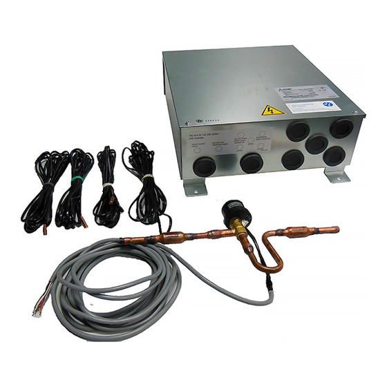
- Page 2 [Fig. 2.0.1] 1 Controller 2 LEV-kit 3 Thermistor 4 Clip 5 Insulation 6 Tie band 7 Installation manual 8 Tube [Fig. 3.0.1] A Air handling unit controller · (PAC-AH M-J) B Air handling unit (field supply) C Controller (field supply) D Outdoor unit E Heat exchanger (field supply) F Gas pipe...
- Page 3 [Fig. 4.2.1] A Controller B Screw (field supply) [Fig. 6.2.1] [Fig. 6.2.2] A Remove the cap A Heat exchanger (field supply) B LEV-kit Type 125 - 140 C Brazing D Linear expansion valve E Outdoor unit [Fig. 6.2.3] A Heat exchanger (field supply) B LEV-kit C Brazing D Linear expansion valve...
- Page 4 [Fig. 6.3.1] A Heat exchanger (field supply) B Gas pipe C Thermistor (gas pipe) D Aluminum tape (field supply) E Insulation F Tie band [Fig. 6.3.2] A Heat exchanger (field supply) B Gas pipe C Thermistor (liquid pipe) D Aluminum tape (field supply) E Insulation F Tie band G Capillary tube...
- Page 5 [Fig. 7.1.1] A Switch 16 A B Overcurrent protection 16 A C Indoor unit D Pull box [Fig. 7.2.1] [Fig. 7.2.2] A Terminal block for AHU controller/ M1M2 M1M2 M1M2 M1M2 M1M2 M1M2 indoor transmission cable B Terminal block for outdoor transmis- sion cable C Remote controller [Fig.
-
Page 6: Table Of Contents
Do not reconstruct or change the settings of the protection devices. <Color: yellow> - If the pressure switch, thermal switch, or other protection device is shorted and operated forcibly, or parts other than those specified by Mitsubishi Elec- tric are used, fire or explosion may result. Warning: •... -
Page 7: Before Getting Installed
• Do not use a refrigerant other than R410A. • Use power line cables of sufficient current carrying capacity and rating. - If another refrigerant (R22, etc.) is used, the chlorine in the refrigerant may - Cables that are too small may leak, generate heat, and cause a fire. cause the refrigerator oil to deteriorate. -
Page 8: System Component
3. System component [Fig. 3.0.1] (P.2) Max. capacity (kW) 12.5 16.0 18.0 25.0 31.5 50.0 63.0 · A Air handling unit controller (PAC-AH M-J) Min. capacity (kW) 10.0 12.5 16.0 18.0 25.0 40.0 50.0 B Air handling unit (field supply) Condensing temperature =TC Choose TC satisfying a condenser design C Controller (field supply) -
Page 9: Selecting An Installation Site And Installing The Controller
4. Selecting an installation site and installing the controller 4.1. Combining indoor units with outdoor • Avoid locations in direct sunlight. • Avoid locations exposed to outside air. units • Avoid locations exposed to the elements or water splashes. • Avoid locations exposed to stream or oil vapour. -
Page 10: Electrical Wiring
6.3.1 Thermistor for gas pipe 6.3.2 Thermistor for liquid pipe Put the thermistor as close as possible to the branch pipe that is located the clos- Put the thermistor on the coldest position to prevent the evaporator from freezing. est to the gas pipe (header) connection on the evaporator (field supply). Turn the lead wire of the thermistor downward, and wind the aluminum tape (field Turn the lead wire of the thermistor downward, and wind the aluminum tape (field supply) around the pipe to fix the thermistor. -
Page 11: Power Supply Wiring
Do not route the thermistor cables together with power cables. • In the case of Class B fuse rated 15 A or 20 A, NF model name (MITSUBISHI): NF30-CS (15 A) (20 A) 7.4. Connecting distant signal line NV model name (MITSUBISHI): NV30-CA (15 A) (20 A) Use an earth leakage breaker with a sensitivity of less than 30 mA 0.1 s. -
Page 12: External I/O Specifications
7.5. External I/O specifications Defrost X: Relay (field supply) signal AC220~240 V 1 A Caution: A defrost signal is output in defrosting. Be careful to miscarriage lines 1. Wiring should be covered by insulation tube with supplementary insula- because over AC200 V is impressed in ON. tion. -
Page 13: Setting Temperature Control
8.3. Setting temperature control 8.4. Dip-switch function Thermostat condition in controlling the discharge air temperature Change of discharge or suction air temperature control TH21: Discharge air temperature Dip switch TH24: Suction air temperature Thermostat control Remarks SW7-2 To: The preset temperature on the remote controller * The value indicated by boldface in the table below can be changed by a Suction / return —... - Page 16 Please be sure to put the contact address/telephone number on this manual before handing it to the customer. HEAD OFFICE: TOKYO BLDG., 2-7-3, MARUNOUCHI, CHIYODA-KU, TOKYO 100-8310, JAPAN Authorized representative in EU: MITSUBISHI ELECTRIC EUROPE B.V. HARMAN HOUSE, 1 GEORGE STREET, UXBRIDGE, MIDDLESEX UB8 1QQ, U.K . WT05932X01...
Need help?
Do you have a question about the PAC-AH125 and is the answer not in the manual?
Questions and answers