
Related Manuals for Omron ZW-8000 Series


Summary of Contents for Omron ZW-8000 Series
- Page 1 Displacement Sensor ZW-8000/7000/5000 series Confocal Fiber Type Displacement Sensor User’s Manual ZW-8000@ ZW-7000@ ZW-5000@ Z362-E1-09...
- Page 2 Introduction Thank you for purchasing the ZW-8000/7000/5000 Series. This manual provides information regarding functions, performance and operating methods that are required for using the ZW-8000/7000/5000 Series. When using the ZW-8000/7000/5000 Series, be sure to observe the following: • The ZW-8000/7000/5000 Series must be operated by personnel knowledgeable in electrical engineer- ing.
- Page 3 Terms and Conditions Agreement (Please Read) Basic configuration User's Manual Installation and Connections Operation during RUN Mode Settings for Function Convenient Functions Offline Settings Sensor controller operations Troubleshooting APPENDICES Confocal Fiber Type Displacement Sensor ZW-8000/7000/5000 Series...
- Page 4 Omron’s exclusive warranty is that the Products will be free from defects in materials and workmanship for a period of twelve months from the date of sale by Omron (or such other period expressed in writing by Omron). Omron disclaims all other warranties, express or implied.
- Page 5 Performance Data. Data presented in Omron Company websites, catalogs and other materials is provided as a guide for the user in determining suitability and does not constitute a warranty. It may represent the result of Omron’s test conditions, and the user must correlate it to actual application requirements. Actual performance is subject to the Omron’s Warranty and Limitations of Liability.
- Page 6 Precautions on Safety ● Symbols and the meanings for safety precautions described in this manual. In order for the product to be used safely, the following indications are used in this book to draw your attention to the cautions. The cautions with the indications describe the important contents for safety.
- Page 7 Warning This product is not designed or rated for ensuring safety of persons either directly or indirectly. Do not use it for such purposes. Do not disassemble the product. Doing so may cause electric shock due to the high voltage portion.
- Page 8 Warning When using an intranet environment through a global address, connecting to an unauthorized terminal such as a SCADA, HMI or to an unauthorized server may result in network security issues such as spoofing and tampering. You must take sufficient measures such as restricting access to the terminal, using a terminal equipped with a secure function, and locking the installation area by yourself.
- Page 9 Recommended power supply: S8VS-06024 (Omron, 24 VDC 2.5 A 60 W) • The supply voltage must be within the rated range (24 VDC ± 10 %).
- Page 10 • Handling fiber cables Use them in compliance with the following. This may result in damage to the fiber cable. - Fiber cable bend radiuses must be at least 20 mm. - Do not yank hard on a fiber cable. - Do not step on a fiber cable or place anything heavy on it.
- Page 11 • Whenever any trouble, including, strange odor smelled, the body overheated or smoke escaped, was found, immediately stop the operation, and consult an OMRON branch or sales office with the system shut down. • Do not drop or make a strong impact on the unit.
- Page 12 • Cannot remove the Fiber interface of Sensor Head. If you accidentally remove it, need to repair. ZW-XF80@@R is suitable for the ZW-8000 series, ZW-XF70@@R is suitable for the ZW-7000 series, and ZW-XF50@@R for the ZW-5000 series. Only one cable can be extended.
- Page 13 4. Maintenance and Inspection • Do not use thinner, benzene, acetone or kerosene to clean the Sensor Head, fiber cable and Sensor Controller. If large dust particles adhere to the emitter/receiver of the Sensor Head or Sensor Controller, use a blower brush (used to clean camera lenses) to blow them off.
-
Page 14: Editor's Note
Optional Copyrights and Trademarks • Sysmac is a trademark or registered trademark of OMRON corporation in Japan and other countries for our FA equipment products. • Windows, Windows XP, Windows Vista, Windows 7, and Windows 8 are registered trademarks of Microsoft Corporation in the USA and other countries. -
Page 15: Relevant Manuals
Relevant Manuals The following table provides the relevant manuals for the ZW-8000/7000/5000 series Confocal Fiber Type Displacement Sensor. Read all of the manuals that are relevant to your system configuration and application before you use the ZW- 8000/7000/5000 series Confocal Fiber Type Displacement Sensor. Most operations are performed from the Sysmac Studio Automation Software. -
Page 16: Related Manuals
Related Manuals The following manual is related to Controllers. Use this manual for reference. Manual name Cat. No. Model numbers Application Description Sysmac Studio Version 1 W504 SYSMAC-SE2@@@ Learning about the operating Describes the operating proce- Operation Manual procedures and functions of dures of the Sysmac Studio. -
Page 17: Table Of Contents
Table of Contents Editor's Note ........... 12 Copyrights and Trademarks . - Page 18 Installation of Sensor Controller ........66 Attaching the strap to the Calibration ROM .
- Page 19 3-7 Displaying saved measured values......113 3-8 Performing internal logging ....... . 114 Internal logging by Sysmac Studio .
- Page 20 Clearing the Bank Settings ........188 Setting the Bank Mode .
- Page 21 Calculating ........... . 239 7-8 Setting the Output Conditions .
- Page 22 Index ........... . . 329 Revision History .
- Page 23 ZW-8000/7000/5000 User's Manual...
-
Page 24: Search From Settings
Search from Settings Settings Set by Sysmac Studio Set by Sensor Controller Setting the Material for the Target to Measure p.125 p.230 Setting the Exposure Time Control Mode p.122 p.237 Setting Exposure Time Control Mode p.129 p.232 Measuring the Height p.138 p.237 Measuring the Thickness... -
Page 25: Basic Configuration
Basic configuration 1-1 ZW-8000/7000/5000 Series Displacement Sensors ....24 1-2 Basic Operation Flow........25 1-3 Basic Operations for Displaying Measurement Results . -
Page 26: Zw-8000/7000/5000 Series Displacement Sensors
1-1 ZW-8000/7000/5000 Series Displacement Sensors The ZW-8000/7000/5000 Series is a line of fiber coaxial displacement sensors. They consist of Sensor Head and Sensor Controller, Calibration ROM, and exclusive setting PC tool which runs on personal computers for system settings and monitoring. Sensor head Sensor Controller PC tool... -
Page 27: Basic Operation Flow
1-2 Basic Operation Flow The following is the basic operation flow for ZW-8000/7000/5000 Series. Installation and connection Section 2 Installation and Connections Install the sensor head. Preparation Default settings for connecting Section 2 Installation and Connections for measurement the sensor head. Set the extension fiber cable length. - Page 28 Setting Threshold Value 4-4 Setting Threshold Value Functions used Switching Banks 3-9 Bank Switching during operation Executing Zero Reset 3-4 Perform the Zero Reset Setting I/O (analog/judgment) Section 2 Parallel I/O connection (*) Using EtherCAT Communications Section 3 EtherCAT Connection (*) Section 4 EtherNet/IP Connection (*) EtherNet/IP Communications Operations and...
-
Page 29: Multi-Task And Bank Data
Multi-task and Bank Data Multi-task Function With the ZW-8000/7000/5000 Series, you can set multiple measurement processing for one sensing setting. This measurement processing is called a “task (TASK).” Example: When measuring height and side run-out at the same time Surface fluctuation (TASK2) Height (TASK1) For tasks, TASK1 to TASK4 are available for registration. - Page 30 Bank Data ZW-8000/7000/5000 Series can hold up to eight sets of sensing settings, which are called “bank (BANK)”. When the setup is changed, the bank can be switched externally. What is Bank? The sensing settings for measurement are held as one bank. Sensing Sensing Filter...
-
Page 31: Basic Operations For Displaying Measurement Results
1-3 Basic Operations for Displaying Measurement Results This section describes a series of operations, from setting up the Sensor Head and Sensor Controller and connecting to the PC tool (Sysmac Studio), to calibrating the Sensor Head, through to monitoring the measurement results. - Page 32 ZW-SP/SPR Series When installing with accessory (installation plate) Place the accessory (installation plate) between the sensor head and the object you want to fix the sensor head to. Place the sensor head an appropriate distance from the target to measure, and then fix it by tight- ening four accessory screws (M2 ×...
- Page 33 When installing with recommended installation jig (Misumi SHMPS12) Place the sensor head between the 2 parts of the recommended installation jig (Misumi SHMPS12 series). Fix it by tightening the M4 fixing screws. Tightening torque: 1.2 N · m ● ZW-SP Series ●...
- Page 34 Installation precautions Use flat head screws. Fix it within the shaded area in the figure below. Tightening torque: 0.15 N · m (M2 screw) or 0.5 N · m (M3 screw) ● ZW-SP Series ● ZW-SPR Series 35.4 41.4 22.1 28.1 41.4 35.4...
-
Page 35: Attaching The Strap To The Calibration Rom
Attach the supplied strap to the Calibration ROM. Calibration ROM Strap Attach the Calibration ROM to the fiber cable of the Sensor Head. ● ● ZW-7000 Series ZW-8000 Series ● ZW-5000 Series ZW-8000/7000/5000 Basic Operations for Displaying Measurement Results User's Manual... -
Page 36: Attaching The Strap To Protective Cap
Attaching the Strap to Protective Cap ZW-8000 Series: Attach the supplied protective cap to the fiber cable. ZW-7000 Series: Attach the strap supplied with the protective cap to the fiber cable. ZW-5000 Series: Attach the supplied protective cap to the fiber cable. -
Page 37: Connecting The Sensor Controller And Sensor Head
Connecting the sensor controller and sensor head Connect the fiber connector of Sensor Head to the fiber adapter of Sensor Controller. Remove the Protective cap of Fiber cable. ● ZW-8000/5000 Series ● ZW-7000 Series ZW-8000/7000/5000 Basic Operations for Displaying Measurement Results User's Manual... -
Page 38: Connection Of Fiber Cable And Sensor Controller
Connection of Fiber Cable and Sensor Controller Connect the fiber cable to the Sensor Controller. ZW-8000 Series When connecting the fiber cable, mate the convex section of the fiber connector and the groove on the sensor controller fiber adapter. Make sure to grasp the bushing section of the fiber connector when you connect to the Fiber cable. - Page 39 ZW-7000 Series Connect the Fiber cable and Calibration ROM to the Sensor Controller. Make sure to have the bush section of the Fiber cable when you connect to the Fiber cable. Fiber Cariblation adapter Groove of fiber adapter Convex of fiber Fiber connector connector Bush section...
-
Page 40: Connection Of Calibration Rom And Sensor Controller
ZW-5000 Series When connecting the fiber cable, mate the convex section of the fiber connector and the groove on the sensor controller fiber adapter. Mate the convex section of the fiber connector with the groove on the fiber adapter and turn the threaded section clockwise while pushing in (see figure 1). -
Page 41: Remove The Fiber Cable
When you remove the fiber cable, make sure to have the black part of the connector which indi- cated. Have the fiber connector (black part) illustrated under figure, and then pull out the direction of the arrow. ZW-8000 Series ZW-7000 Series Important If you have the bush section of Fiber cable, that part may be out of place. - Page 42 For ZW-5000 Series Turn the threaded section of the fiber cable counter-clockwise. When the screw comes off, pull the cable out. Important • Handling fiber cables Use them in compliance with the following. This may result in damage to the fiber cable. - Fiber cable bend radiuses must be at least 20 mm.
- Page 43 • Contact [Request for an Estimate] URL http://www.ntt-at.com/product/optical_cleaner/Distributors.html [Technical and other inquiries] Company NTT Advanced Technology Corporation Address Muza Kawasaki Central Tower, 1310 Omiya-cho Saiwai-ku, Kawasaki-shi, Kanagawa, 212-0014, Japan +81 44 589 5894 http://www.ntt-at.com/product/optical_cleaner/Distributors.html • When you remove the fiber cable from Sensor Controller, make sure to attach the protective cap. If you do not attach it, it is possible that some contaminants may have adhered and may cause degradation of performance.
-
Page 44: Input Terminal Block
24 V input terminal block Used for 24 VDC power supply. Compatible wire specifications: Solid wire 0.2 to 2.5 mm Stranded wire 0.2 to 2.5 mm Stranded wire with rod terminal(no plastic sleeve) 0.25-2.5 mm Stranded wire with rod terminal(with plastic sleeve) 0.25-2.5 mm AWG 24-12 Pin processed length 10(±0.5) mm Signal name... - Page 45 Insert the wire into the terminal hole. • When you use a wire attached rod terminal, you can in- sert just with Push-IN. • When using single wire, or stranded wire Insert the wire deeply in to the terminal hole while pushing the release button on the side of terminal hole using a screwdriver.
-
Page 46: Connecting To A Personal Computer
Connecting to a Personal Computer Connect a personal computer and the Sensor Controller through an Ethernet cable to perform sensor settings and monitoring from Sysmac Studio. Insert one end of the Ethernet cable into the Ethernet Ethernet connector connector of the controller. Insert another end of the Ethernet cable into the Ethernet connector of the external device. - Page 47 For Windows 7 Select [Control Panel] from the start menu. The [Control Panel] dialog box appears. Click [Network and Internet], and [View net- work status and tasks]. Click [Change adapter settings]. Right-click [Local Area Connection] and se- lect [Properties] from the displayed menu. The [Local Area Connection Properties] dialog box appears.
- Page 48 Under the [Network] tab, double-click [Internet Protocol Version 4 (TCP/IPv4)]. The [Internet Protocol Version 4 (TCP/IPv4) Prop- erties] dialog box appears. Click the [Use the following IP address] option and enter an IP address and subnet mask. Example: When matching the computer settings to the Sen- sor controller's network address and setting the following values: IP address: 192.168.250.2...
-
Page 49: Starting Up Sysmac Studio Measurement Sensor Edition
Starting Up Sysmac Studio Measurement Sensor Edition Start up Sysmac Studio. Create a new project for the ZW. From Category, select [Measurement Sensor] and from Device, select [ZW] to click the [Cre- ate] button. Note If you have a previously created project, click [Open Project] to select the project. 2-8 Saving a project p.93 Select the [Specify a sensor] radio button to specify the IP address of the Sensor Con-... -
Page 50: Calibrating Sensor Head
Calibrating Sensor Head Calibrate the Sensor Head by obtaining the dark data in the no-incoming light status. • When removing and inserting a fiber cable from/to the Sensor Controller (Including the initial connection). • When extending a fiber cable. • When “Dark” is shown in the main display even though a measurement object exists in the measurement range. - Page 51 Click [Execute sensor head calibration]. The sensor head calibration window appears. With no object in the measuring range, or with the tip of the sensor head shielded from light by an object that has the characteris- tics of diffusion reflection, click the [Execute sensor head calibration] button.
- Page 52 Note Calibrating Sensor Head can also be set by the operating keys on the Sensor Controller. Calibrating Sensor Head p.270 Basic Operations for Displaying Measurement Results ZW-8000/7000/5000 User's Manual...
-
Page 53: Monitoring The Measurement Results
Monitoring the Measurement Results After the completion of sensor head calibration, check that measurement is performed correctly. Multi View Explore : [Device Group] | [(Sensor Name)] (right-click) Select [Sensing Monitor]. Open the sensing monitor window. If the displayed measurement results are incor- rect, refer to Chapter 8 Troubleshooting. - Page 54 MEMO Basic Operations for Displaying Measurement Results ZW-8000/7000/5000 User's Manual...
-
Page 55: Installation And Connections
Installation and Connections 2-1 System Configuration ........54 2-2 Part Names and Functions . -
Page 56: System Configuration
2-1 System Configuration System Configuration Connecting with EtherCAT EtherCAT Master Sysmac Studio (when the master is NX/NJ Series) Standard Edition NX/NJ-series Machine Automation Controller I/O control PLC General-purpose USB Cable General-purpose Ethernet Cable Special EtherCAT Cable (RJ45/RJ45) 24-V ZW-8000□/ZW-7000□/ZW-5000□ Trigger input power supply sensor Other EtherCAT slaves... -
Page 57: Connection Compatibility
Connection Compatibility Connected to Other connection ZW-8000@ EtherCAT EtherNet/IP Ethernet RS-232C Parallel I/O Cable ZW-7000@ (no-protocol) (no-protocol) ZW-5000@ EtherCAT Not compatible Compatible Compatible Compatible EtherNet/IP Not compatible Compatible Compatible Compatible Ethernet Compatible Compatible Compatible Compatible (no-protocol) RS-232C Compatible Compatible Compatible Compatible (no-protocol) Important... - Page 58 Product Model Application Industrial EtherNet/IP / • W4S1-03B The Switching Hub connects multiple Sensors to one Touch Finder or one Ethernet Switching Hub computer running PC Tool. (3 ports type) • W4S1-05B • W4S1-05C (5 ports type) EtherCAT Junction Slave •...
-
Page 59: Part Names And Functions
2-2 Part Names and Functions The following describes the names and functions of parts of the Sensor Head, Calibration ROM and Sensor Controller. Sensor Head ● ZW-S80@@ ● ZW-SP80@@ ● ZW-SPR80@@ ● ZW-SP70@@ ● ZW-SPR70@@ ● ZW-S70@@ ● ZW-S50@@ ● ZW-SP50@@ ●... -
Page 60: Calibration Rom
Calibration ROM This ROM is associated with the sensor on a one-to-one basis, and operates connected to the Sensor Controller. Names Functions Serial number Serial number. Only a Sensor Head with the same serial number is available. Important • Use with the Calibration ROM always connected. If the Calibration ROM is not connected, the error message “SYSERR”... -
Page 61: Sensor Controller
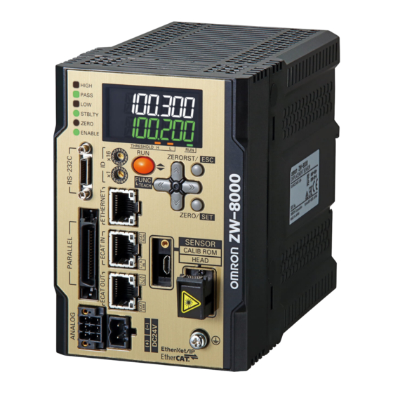
Sensor Controller Sensor Controller ZW-8000@ ZW-7000@ <Front View> <Front View> Display Display Control Panel Control Panel Connectors/terminals Connectors/terminals <Rear view> ZW-5000@ <Front View> Display <Bottom view> Control Panel Connectors/terminals ZW-8000/7000/5000 Part Names and Functions User's Manual... - Page 62 Front view ● Display Names (light color) Functions HIGH indicator (orange) The HIGH indicator is lit while judgment is resulted in HIGH (HIGH threshold value < measured value). The PASS indicator is lit while judgment is resulted in PASS (LOW threshold value ≤ PASS indicator (green) measured value ≤...
- Page 63 ● Connectors/terminals Names Functions RS-232C connector Connect the RS-232C cable when you are connecting the system with a PLC or personal computer through RS-232C. For the RS-232C cable, please use the following exclusive products: If you use a cable not included in the exclusive products, a false operation or breakdown may result.
- Page 64 ECAT status indicator LED LED name Color Status Contents ECAT RUN indicator Green Initialization status Blinking Pre-Operational status Single flash Safe-Operational status Operational status ECAT ERROR indicator No error Blinking Communication setting error or PDO mapping error Single flash Synchronization error or communications data error Double flash Application WDT timeout PDI WDT timeout...
-
Page 65: Installation
2-3 Installation Installation of Sensor Head Installation of Sensor Head p.29 Measuring range With the ZW-8000/7000/5000 series, the measurement center distance is expressed as 0 with the NEAR side as + and the FAR side as -. ● ZW-S series ●... - Page 66 ZW-8000 series measurement cycle and measurement range With the ZW-8000 series, the setting value of the measurement cycle changes in 1-us increments from 60 μs to 100 μs. The near side is fixed, and the measurement range is shortened due to the measurement range ratio of each measurement cycle.
- Page 67 Mutual interference When using two or more Sensor Heads in opposition to each other, mutual interference will not occur if other beam spots are outside the ■ areas in the following diagrams. 6.7 mm 9.3 mm 0.6 mm 1.4 mm 1.6mm 2.8mm ●...
-
Page 68: Installation Of Sensor Controller
Installation of Sensor Controller Precautions for installation Install the Sensor Controller in the orientation indicated by the circle mark in the following figure. Do not install it laying on its side or upside down. For adequate intake and/or exhaust, keep the Sensor Controller clear by 30 mm or more on its top, and by 10 mm or more from either side. - Page 69 Installing on the DIN track The following describes how to attach the Sensor Controller on a 35 mm-wide DIN track. DIN track (option) PFP-100N (1 m) PFP-50N (0.5 m) PFP-100N2 (1 m) End plate (option) PFP-M Installation procedure Hook the upper edge of the Sensor Controller's back slot onto the upper edge of the DIN track.
- Page 70 Installing on bottom The following describes how to attach the Sensor Controller on its bottom. Drill four installation holes on the base. Important For the location installation holes, see the external dimensions. 9-1 Specifications and External Dimensions p.288 Tighten four M4 screws to fix the Sensor Controller on the base.
-
Page 71: Attaching The Strap To The Calibration Rom
Attaching the strap to the Calibration ROM Attaching the strap to the Calibration ROM p.33 Attaching the Strap to Protective Cap Attaching the Strap to Protective Cap p.34 Connection of Fiber Cable and Calibration ROM Connecting the sensor controller and sensor head p.35 Connection of Fiber Cable and Sensor Controller Connection of Fiber Cable and Sensor Controller p.36 Connection of Calibration ROM and Sensor Controller... -
Page 72: Cleaning The Fiber Connector And Fiber Cable Using Zw-Xcl
Cleaning the fiber connector face of the Controller side. For ZW-8000 Series Insert the cleaner end into the fiber connector or connection adapter, then turn it in the same direction about 3 times while pressing it against the side surface and end surface of the optical connector. - Page 73 For ZW-7000 Series Open the shutter of the fiber connector, and then wipe the fiber's face around three reciprocating. For ZW-5000 Series Insert the cleaner end into the fiber connector or connection adapter, then turn it in the same direction about 3 times while pressing it against the side surface and end surface of the optical connector.
- Page 74 Cleaning the Sensor Head connection of the fiber cable For ZW-8000 Series Remove the cap from the fiber connector and wipe the fiber's face with about 3 passes. For ZW-7000 Series Remove the cap from the fiber cable and wipe the entire end surface of the fiber connector with about 3 passes.
- Page 75 For ZW-5000 Series Remove the cap from the fiber connector and wipe the fiber's face with about 3 passes. Important • The cleaner can only be used one time. Reusing the cleaner may result in dirt or scratches on the end surface, causing malfunctions or measurement errors.
-
Page 76: Extending Fiber Cable
To extend the fiber cable on the Sensor Head, use an extension fiber cable and connecting adapter. Important When extending the fiber cable, be sure to set the fiber cable length and calibrate the Sensor Head after connecting the extension fiber cable. ZW-8000 Series Connection adaptor ZW-XFCS Nameplate... - Page 77 ZW-7000 Series Nameplate Connection adaptor ZW-XFCM Sensor Head Extension fiber cable fiber cable ZW-XF70□□R: (2m/5m/10m/20m/30m) When connecting the fiber cable, grasp by the bushing part of fiber. Align the convex section of fiber cable to the groove of the adapter and insert it until there is a clicking sound. Fiber connector Groove Convex section...
- Page 78 ZW-5000 Series Connection adaptor ZW-XFC2 Sensor Head Extension fiber cable fiber cable ZW-XF50@@R: (2m/5m/10m/20m/30m) Mate the convex section of the fiber connector with the groove on the connection adapter and turn the threaded section clockwise while pushing in. Convex section Groove When the fiber insertion/fixing screw is not completely tightened, as is the case in the "No good"...
-
Page 79: Calibrating Sensor Head
In this case, need to repair. Contact your OMRON representative. When inspect a object with high reflectivity, visually check may not be allowable. Use and conform a diffused object. -
Page 80: Wiring
2-4 Wiring 32-pole extension connector Used for judgment output, control input, etc. Compatible connector: FX2B series (Hirose Electric Co., Ltd.) A parallel cable (ZW-XCP2E) for a 32-pole extension connector with 2 m wire is included. (*1 ) (*2 ) (*1 ) Color Signal name Signal name... - Page 81 Class Name Description Parallel HIGH output This outputs judgment results - HIGH (HIGH threshold values < Measured value). output This outputs judgment results - PASS (LOW threshold values ≤ Measured value ≤ HIGH PASS output threshold values). LOW output This outputs judgment results - LOW (LOW threshold values > Measured value). ALARM output This turns ON when there is a system error.
- Page 82 Class Name Description Parallel ZERO input This is used to execute and clear a zero reset. input RESET input This resets all executing measurements and outputs. While a RESET is being input, judgment output conforms to the non-measurement setting. If this RESET input switches ON while the hold function is used, the state in effect before the hold function was set will be restored.
-
Page 83: Analog Output Terminal Block
Analog output terminal block Used for analog output. Compatible wire specifications: Solid wire 0.2 to 1.5 mm Stranded wire 0.2 to 1.5 mm Stranded wire with rod terminal(no plastic sleeve) 0.25-1.5 mm Stranded wire with rod terminal(with plastic sleeve) 0.25-0.75 mm AWG 24-16 Pin processed length 10 (±0.5) mm Signal name... -
Page 84: Input Terminal Block
Loosen the two fixing screws using a screwdriver to remove Analog output terminal block from the Sensor Controller. Fixing Screws (both end) Insert the wire into the terminal hole. • When you use a wire attached rod terminal, you can in- sert just with Push-IN. -
Page 85: Electrical Specifications
Electrical Specifications Input circuit Item Specifications Model ZW-8000@/7000@/5000@ Input type For NPN connection For PNP connection Input voltage 24 VDC±10%(21.6 to 26.4 VDC) 24 VDC±10%(21.6 to 26.4 VDC) Input current 7 mA Typ. (24 VDC) 7 mA Typ. (24 VDC) ON voltage/ON current 19 V min./3 mA min. - Page 86 Output circuit Item Specifications Model ZW-8000@/7000@/5000@ Output type For NPN connection For PNP connection Output voltage 21.6 to 30 VDC 21.6 to 30 VDC Load current 50 mA max. 50 mA max. ON residual voltage 2 V max. 2 V max. ON leakage current 0.1 mA max.
-
Page 87: Installing The Sysmac Studio
2-5 Installing the Sysmac Studio The PC Tool used to set up ZW-8000/7000/5000 Series Displacement Sensors is installed from the Sysmac Studio Installer. Refer to the Sysmac Studio Version 1 Operation Manual (Cat. No. W504) for the system requirements and installation procedure. ZW-8000/7000/5000 Installing the Sysmac Studio User's Manual... -
Page 88: Launching A Project
2-6 Launching a project Connecting to the sensor with Sysmac Studio Measurement Sensor Edition Creating a new project Create a new project, add a sensor to the project, then start communicating with the sensor. Start up the PC tool. Create a new project. Click [New Project] and select [Displacement Sensor] from [Category] under [Select Device], and [ZW] from [Device]. -
Page 89: Entering Project Information
After the sensor is connected, the following window appears. Sensing monitor window appears on the Edit pane. The sensor starts up in RUN mode. Adding a sensor to a project After the project is created, additional sensors can be added to the project. ... -
Page 90: Explanation Of Screen Sections
2-7 Explanation of Screen Sections PC tool The following summarizes the names and functions of the window sections of Sysmac Studio. Sysmac Studio Main window For displacement sensor (ZW) projects Name Description Menu bar Menu items that can be used with this tool is displayed. Toolbar Tool functions that can be used with this tool is displayed with icons. - Page 91 Multi-view explore Name Description Sensor model Displays the sensor model. Displays online/offline status at the end. Bank group This is a group of bank data. Bank data can be registered up to 8 in NORMAL mode, and up to 32 in JUDGMENT VALUE mode. Bank data This is used to set functions to perform measurements.
- Page 92 Edit pane The Edit Pane changes as shown below based on what is selected in the Multi View Explore. System data setting pane Main pane Bank data pane Sensing monitor pane Trend monitor pane Name Description Menu icon Parameters to be edited on each edit pane can be changed. Setting item Each setting item can be edited.
- Page 93 List of icons (1) Menu icon Edit pane type Icon Menu name Description Main pane General settings Sensor project information can be verified. Online Switching between online and offline connections with the actual sensors, and switching the operating mode can be performed. Also, the internal logging process, saving set data, monitoring the measurement results can be performed.
- Page 94 (2) Operation icons Sensing monitor window Icon Name Description Zoom in Zoom in the line bright. Zoom out Zoom out the line bright. Fit to frame Change the size of the line bright so it fits the window size. Export Saves the line bright being displayed.
-
Page 95: Saving A Project
2-8 Saving a project Saving a project Save the project being edited with the PC tool. The project to be saved has the following information. Configuration data Description Project information Information on the sensor registered in this project. Entire sensor information Entire sensor information. - Page 96 MEMO Saving a project ZW-8000/7000/5000 User's Manual...
-
Page 97: Operation During Run Mode
Operation during RUN Mode 3-1 Setting the Measurement Start Timing......96 3-2 Switching operation modes........98 3-3 Displaying Measured Values and Received Light Waveform . -
Page 98: Setting The Measurement Start Timing
3-1 Setting the Measurement Start Timing Internal Processing of Sensor Controller The Sensor Controller performs processing in the following 3 parts according to the logical beam sent from the Sensor Head. Since each part is performed in parallel inside the Sensor Controller, the measurement cycle is determined by the part with the longest processing time. -
Page 99: Measurement Mode And Measurement Start Timing
Measurement Mode and Measurement Start Timing The procedure for specifying the measurement start timing can be selected from the following three modes. Use these modes to synchronize the measurement timing between sensors or to perform synchronization control with a servomotor or other external devices. Item Setting item Setting value... -
Page 100: Switching Operation Modes
3-2 Switching operation modes The Sensor Controller has two operation modes. One is RUN mode/Setup mode and the other is FUNC mode. Switch to the desired mode depending on purpose. (The Sensor Controller always starts up in the RUN mode when the power is turned on.) Item Setting item Mode... -
Page 101: Displaying Measured Values And Received Light Waveform
3-3 Displaying Measured Values and Received Light Waveform The measurement values and received light waveform can be displayed. Multi View Explore : [Device Group] | [(Sensor Name)] (right-click) Select [Sensing monitor]. On the edit pane, the [Sensing monitor] window appears. -
Page 102: Perform The Zero Reset
3-4 Perform the Zero Reset Zero reset What is Zero Reset? This function allows resetting the measured value to “0” at any timing during measurement in the RUN mode. The measured value can be displayed and output as a positive or negative deviation (tolerance) from the set reference value “0”. - Page 103 Example 3: Measure the level difference of the sensing object (execute zero reset at every measurement) Sensor head This step is measured. Zero reset Zero reset Zero reset executed executed executed Direction of movement The zero reset function also allows setting the reference value to the hold value for a hold measurement or any value other than zero.
- Page 104 Important • When a zero reset is executed, the analog output becomes the voltage or current value at the center of the two preset points. Analog output becomes roughly 0 V or 12 mA when focus is not set. “2-1 Parallel I/O connection” described in Displacement Sensor ZW-8000/7000/5000 series Confocal Fiber Type Displacement Sensor User’s Manual for Communications Settings (Z363) •...
-
Page 105: Displaying Measured Values In Graphs
3-5 Displaying measured values in graphs The measured values can be displayed in graphs. Important This function can only be used with project of the displacement sensor (ZW). With project of the controller (NJ), you can use the “Data trace” function to display graphs of measured values. Allowable setting range of sampling interval is 500 µs to 100 ms. - Page 106 Select data to monitor the trend for. Set data to monitor the trend for. The types of data that can be set are as follows. Item Setting item Description Target data OUT1 Measurement results assigned to OUT1 OUT2 Measurement results assigned to OUT2 OUT3 Measurement results assigned to OUT3 OUT4...
-
Page 107: Specifying The Sampling Start And End Conditions
Specifying the sampling start and end conditions You can specify the conditions for starting and ending sampling. Check the Trigger start conditions/Trigger end conditions checkbox. Select the trigger condition. Item Setting item Range Description Trend setting Trigger start Parallel I/O are specified as the trigger condition the conditions following: TIMING, ZERO, BUSY, ENABLE, HIGH, PASS, LOW,... - Page 108 Select the trigger target. Item Setting item Range Description Trigger target TIMING TIMING input signal (parallel I/O) ZERO ZERO input signal (parallel I/O) BUSY BUSY output signal (parallel I/O) ENABLE ENABLE output signal (parallel I/O) HIGH HIGH output signal (parallel I/O) PASS PASS output signal (parallel I/O) LOW output signal (parallel I/O)
- Page 109 Set the trigger condition. • When the trigger target is “Data slope” Item Setting item Range Description Trigger condition Condition When the measurement results are the same value as the judgment value, the trigger condition is considered to have been met. ≠...
-
Page 110: Starting And Ending Sampling Before And After The Trigger Condition Is Met
Starting and ending sampling before and after the trigger condition is met You can adjust how long to start or end the sampling before or after the condition for starting and ending sampling is met. Measurement value Measurement data satisfied the start condition trigger Sampling interval Sampling start position A Sampling start position B... -
Page 111: Saving Measured Values In A File
3-6 Saving measured values in a file Data sampled with the trend monitor can be exported and imported as a CSV format file. Outputting the results of sampling as a file Sampled measured values can be saved as a CSV format file. A file is prepared each time the trigger condition is met. - Page 112 Item Output items Description TriggerStartObject OUT1 Indicates the target data for the trigger start condition. OUT2 OUT3 OUT4 TIMING ZERO BUSY ENABLE HIGH PASS TASKSTAT LOGGING LOGSTAT LOGERR STABILITY RESET LIGHT_OFF BUFFER_ERR TriggerStartConditions EqualTo Indicates the trigger start condition. NotEqualTo EqualTo: = NotEqualTo: ≠...
- Page 113 Item Output items Description TriggerEndValue1 -999.999999 to 999.999999 mm Indicates the judgment value for the trigger end condition. For data window (in/out), indicates the lower limit. TriggerEndValue2 -999.999999 to 999.999999 mm Indicates the judgment value for the trigger end condition. For data window (in/out), indicates the upper limit.
- Page 114 TriggerEnd True TriggerEndType DataWindowIn TriggerEndObject OUT1 TriggerEndConditions TriggerEndValue1 -0.5 TriggerEndValue2 TriggerEndDelay DataPointsValue ExternalFileStorage FALSE MaxSamplesPerFile 4500 TargetDirectory C:\Omron\Data\DataTrace\ FilePrefix Index (DataName1) (DataName2) 1.21314 1.21314 1.22098 1.22098 0.12334 0.12334 -0.1211 -0.1211 -1.23456 -1.23456 -1.22222 -1.22222 Saving measured values in a file...
-
Page 115: Displaying Saved Measured Values
3-7 Displaying saved measured values You can import a file to which measured values were exported and display those sampling results as a graph. Multi view Explore : [(ZW model name)] (double click) → Edit pane : [Online] icon ( →... -
Page 116: Performing Internal Logging
3-8 Performing internal logging Up to 2000000 data of measurement values can be logged in the Sensor Controller's internal memory. Internal logging can be started or ended using Sysmac Studio, parallel I/O, or non-procedural communications commands. The operating procedures for each method are shown below. Function Sysmac Studio Parallel I/O... - Page 117 Set the logging conditions. Enter the [Data interval], [Number of logging data], and select the stored output data and whether to clear the stored logging data when logging starts. Item Setting item Range Description Data logging Data interval 1 to 1000 Set the data storage interval.
- Page 118 After internal logging ends, click the [Save to file (Sensor → PC)] to output the data to a file. When saving to a file, set the saving start and end points on the following screens, and then press the "Save" button. •...
-
Page 119: Performing Internal Logging With Parallel I/O
Performing Internal Logging with Parallel I/O The logging start and end timings can be specified using LOGGING input signals from parallel I/O. When doing so, follow the procedure below to set the data logging conditions. Multi view Explore : [System] (double-click) →... -
Page 120: Internal Logging With Non-Procedural Commands
Note For the response format of LO commands according to the output data format, refer to following page. “5-1 Connecting by No-protocol Communications” described in Displacement Sensor ZW-8000/ 7000/5000 series Confocal Fiber Type Displacement Sensor User’s Manual for Communications Settings (Z363) Internal logging with non-procedural commands Non-procedural commands can be used to set data logging conditions or the logging start and end timings. -
Page 121: Bank Switching
3-9 Bank switching Switching Banks Switches banks. Double click to open the bank group in the Multi View Explore. Select the bank data to switch and double click or right click it to select the Edit menu. The bank in the Bank data edit pane that is active on the Edit pane becomes the current bank. -
Page 122: Operating With Sensor Controller
3-10 Operating with Sensor Controller Other than using PC tools, ZW-8000/7000/5000 Series can also be operated using the operation keys on the Sensor Controller. For details on how to operate with operation keys, see 7 Sensor controller operations p.209. Operating with Sensor Controller ZW-8000/7000/5000 User's Manual... - Page 123 Settings for Function 4-1 Setting Sensing ......... . 122 4-2 Setting Measurement Items.
-
Page 124: Setting Sensing
4-1 Setting Sensing Setting the Measurement Cycle Set the measurement cycle. Extending the measurement cycle allows you to measure workpieces with lower reflectivity. Item Setting item Setting value Description RUN mode Measurement Refer to the table below. Set the measurement cycle. Cycle Sensor Controller Extension fiber cable... -
Page 125: Setting The Area Mode
Setting the Area Mode Area modes can be used selectively according to the target to measure. Item Setting item Setting value Description RUN mode Area Mode 1 area mode Usually, select this setting. Select this mode when the measurement object is a transparent object 2 area mode and the reflection characteristics of the top surface and rear surface are very different. - Page 126 • When using 2 area mode for the ZW-7000@/5000@, the following hardware and software are necessary. Hardware: The serial number is one of the following or later. ZW-5000@: 0645817 to ZW-7000@: 0825817 to * Serial number format @ @ @ @ @ @ @ (1)(2)(3)(4)(5)(6)(7) Digit Meaning...
-
Page 127: Setting The Material Of The Target To Measure
Setting the Material of the Target to Measure Select the appropriate linearity coefficient setting depending on the target to the measurement. Item Setting item Setting value Description Operation mode Material Normal (default value) A measurement can be performed at specific linearity regardless of the type of target to measure. -
Page 128: Setting The Noise Cut Level
Setting the Noise Cut Level The setting a larger value than the noise level, the noise can be cut. Noise Noise can be cut. Item Setting item Setting value Description Operation mode Noise cut level 0 to 1500 [Gradation] Set the number of gradations when noise is cut from the (default value :300(ZW-8000@), line bright. -
Page 129: Setting Smoothing Size
Setting Smoothing Size When two measurement surfaces are close, the line bright may not be divided. The setting of smoothing size a smaller value, it becomes easy to divide. Smoothing size : 5 Smoothing size : 1 Item Setting item Setting value Description Operation mode Smoothing size... -
Page 130: Setting Start Direction Of Count Measurement Surfaces
Setting Start Direction of Count Measurement Surfaces When a number of measurement surfaces exists, start direction can be selected from NEAR side or FAR side. Example: NEAR Example: FAR 1 surface 4 surface 2 surface 3 surface 3 surface 2 surface 4 surface 1 surface Item... -
Page 131: Setting Light Exposure Time Control Mode
Setting Light Exposure Time Control Mode Set the amount of emitted light (maximum/minimum), amount of emitted light (fixed), and control edge. Item Setting item Setting value Description Exposure time Exposure control Auto (default value) Automatically sets the amount of emitted light within the mode range that does not exceed the specified upper limit. -
Page 132: Setting The Measurement Area
Note • In the sensing monitor window, you can check whether the waveform of received light is obtained correctly as set Displaying Measured Values and Received Light Waveform p.99 • The amount of emitted light cannot be exactly same as setting value [%] and actual control value [%] due to the control resolution difference of Sensor Controller (0.1[μs]). - Page 133 AreaTracks When using the 2 area mode, by setting the reference edge and following edge, the measurement area of Area 2 can be automatically set to follow the workpiece even when it vibrates. Below are examples of when the reference edge is set as the 1st edge and the following edge is set as the 2nd edge. ●...
- Page 134 Item Setting item Setting value Description AreaTracks set- AreaTracks None (initial Area follow is not set. Select this to set any desired value. tings value) Upper line Follows the upper line of Area 2 only. Lower line Follows the lower line of Area 2 only. Upper line and Follows the upper line and lower line of Area 2.
- Page 135 EdgeTracks With ZW-8000@, when using 1 area mode, this function can be used to fix the edge number by setting the possible movement range (track area) of each edge. This function can take stable measurements with no edge number deviation, even when an unstable edge is within the measurement range.
- Page 136 ● When using EdgeTracks 1 sur- 2 sur- 3 sur- 4 sur- face face face face Multiple layers Transparent target The function recognizes the edge found inside the edge 1 track area 2 surface 3 surface 4 surface as edge 1 and the edge found inside the edge 2 track area as edge 2.
- Page 137 EdgeTracks automatically sets the track areas for each measurement cycle. Therefore, it automatically tracks, even when the measurement surface position changes due to target vibration, etc. Example: When measuring transparent target (2 edges) 1 surface 2 surface Transparent target Move target Even if the target is moved, the track areas are followed.
- Page 138 Multiviewer Explore : [BankGroup] | [(Bank Data Name)] (double click) → Edit pane : [Sensing setting] icon ( → Sensing settings window : [Measurement area 1] | [EdgeTracks] Set [EdgeTracks]. Note When the AreaTracks function is turned ON, the EdgeTracks function automatically turns OFF.
- Page 139 When a track area error occurs, the track areas displayed in the Sysmac Studio sensing monitor window within the green boxes are no longer displayed. - When no surfaces are detected - When there are duplicate track areas (Example: When the FAR side (figure 1) for the edge 1 track area and the NEAR side (figure 2) for the edge 2 track area overlap, the edge 1 track area and edge 2 track area become track area errors.) ZW-8000/7000/5000 Setting Sensing...
-
Page 140: Setting Measurement Items
4-2 Setting Measurement Items What is a Measurement Item? Obtain the waveform data based on the specified sensing condition, and calculate the height/thickness of up to four surfaces included in the measuring range. Perform calculations using the output result of each task. Count the measurement surface closest to the Sensor Head first (default value). - Page 141 Item Setting item Setting value Description Height settings Measurement Edge1/Edge2/Edge3/Edge4/ The measurement surface targeted for measurement can surface peak (default value) be switched. The peak is the surface of all measurement surfaces having the highest received light amount. Multi View Explorer : [Bank Group] | [(Bank Data Name)] (double click) →...
-
Page 142: Measuring The Thickness
Measuring the Thickness If you have glass of known thickness, scaling can be adjusted referenced to that glass so that transparent objects can be measured more easily. Sensor head Transparent object Edge 1st Thickness Edge 2nd Item Setting item Setting value Description Thickness Measurement... -
Page 143: Performing Calculations
Note • Thickness measurement can also be set by the operating keys on the Sensor Controller. Measuring the Thickness p.238 • For the setting of measurement area to control of light adjustment, refer to the following: Setting Light Exposure Time Control Mode p.129 Setting Exposure Time Control Mode p.232 Performing Calculations Perform calculations using the results calculated by the tasks. - Page 144 Important Calculates using the measurement value of the last TASK. The timing to update the measurement value of TASK is shifted one cycle by comparing the update timing of the measurement result of reference TASK. Example) TASK1: Height (Edge1) TASK2: Height (Edge1) TASK3: Calculation (X: TASK1, Y: TASK2, M: 1.9, K: 0.0) Measurement count TASK1...
-
Page 145: Setting The Output Conditions
4-3 Setting the Output Conditions Setting Scaling This setting is used when you want to correct any errors that are generated due to the installation status of the Sensor Head, and display the corrected value on the main display as a measured value. There are three types of setting: “auto scaling”... - Page 146 Multi View Explore : [Bank Group] | [(Bank Data Name)] (double click) → Edit pane : [Task Settings] icon ( → Task Settings window : [Scaling] Select [Scaling]. Enter the correction value to [Span] and [Offset]. Note Fixed scaling can also be executed by the operating keys on the Sensor Controller. Performing Manual Scaling p.246 Automatically Setting Scaling Performing 1-point Scaling...
- Page 147 Multi View Explore : [Bank Group] | [(Bank Data Name)] (double click) → Edit pane : [Task Settings] icon ( → Task Settings window : [Scaling] Set the [Scaling] to OFF. Click [Auto setting]. The [Scaling] popup menu appears. Select [Actual scaling (one point)], and click [Next >].
- Page 148 Performing 2-point Scaling Measurement is performed at two positions, and offset values are set for those measured values. Example: When correcting display values to match actual distances Display value (mm) Point 2 -1.0 Measured value (mm) -0.9 -1.0 Point 1 Item Setting item Setting value...
- Page 149 Select [Actual scaling (two points)], and click [Next >]. The [Scaling] popup menu display changes to [1st point settings]. Set correction of the 1st point. Click [STOP] to fix the [Current value], set [Set value] and click [Next >]. The [Scaling] popup menu display changes to [2nd point settings].
- Page 150 Multi-point scaling With ZW-8000@, measurements are taken at multiple locations and a precision stage is used to minimize the measurement error between the measurement value and the actual distance. This function is enabled when nonlinearity occurs in the measurement error of the measurement value and the actual distance.
- Page 151 Multi View Explore : [Bank Group] | [(Bank Data Name)] (double click) → Edit pane : [Task Settings] icon ( → Task Settings window : [Scaling] Click [Auto setting]. The [Scaling] popup menu appears. * This cannot be selected when the scaling checkbox is checked.
- Page 152 Important Arrange the specified current values (measurement values) of Point2 to Point(n) so that they are in ascending or descending order. An error will occur if this relationship is not adhered to. Ascending order Descending order Point1 -1.0000 mm 1.0000 mm Point2 -0.9000 mm 0.9000 mm...
- Page 153 Performing Thickness Scaling The thickness is measured at one position and offset values are set for that measured value. Item Setting item Setting value Description Thickness scaling Setting value -999.999999 to 999.999999 [mm] Correct the measured value, and set the value to display. ...
-
Page 154: Setting Filters
Setting Filters Set the filter condition when filtering information obtained from the sensor before output. The following types of filters can be set depending on purpose. Displacement Profile with no Smooth filter setting Spike-like changes are Median filter removed. [MEDIAN] Changes are smoothed Average filter out. - Page 155 Setting the Median Filter The intermediate value of multiple sets of data can be output as the measurement result. Item Setting item Setting value Description Medial filter Filter mode Median filter is not used. (default value) Outputs the intermediate value of the last three measurements. Outputs the intermediate value of the last nine measurements.
- Page 156 Setting the Average Filter Output measured data as the average value of a preset count. This is set in cases such as to reduce the fluctuation of measurement values and increase the static resolution. Item Setting item Setting value Description Average number Average •...
- Page 157 Setting the Frequency Filter Set a filter to detect the changes in a specific frequency in the measured data. Item Setting item Setting value Description Frequency filter Frequency filter OFF (default value) Frequency filter is not used. Lowpass filter: Detects only frequency components lower than the 0.040 to 23735.000 cut-off frequency.
- Page 158 (2) List of highpass filter cutoff frequencies [Hz] Sensor Controller Extension fiber Lower limit value Lower limit value Upper limit value Upper limit value Initial Value type cable length (1 area mode) (2 area mode) (1 area mode) (2 area mode) ZW-8000@ none 7909...
- Page 159 (4) List of bandpass filter (upper limit) cutoff frequencies [Hz] Sensor Controller Extension fiber Lower limit value Lower limit value Upper limit value Upper limit value Initial Value type cable length (1 area mode) (2 area mode) (1 area mode) (2 area mode) none 7909...
- Page 160 The range of cut-off frequency to be effective in operation varies depending on the setting of measurement cycle. The relationship between the measurement cycle and the cut-off frequency range is shown in the table below. Measurement cycle Sampling Cut-off frequency range [Hz] [μs] Frequency High-pass filter...
- Page 161 Setting the Differentiation Filter Set this filter to detect sudden changes in measured values occurring within an extremely short time. The differentiation filter detects changes in the measured value and current value before a comparison interval. The time of this comparison interval is defined as the differential cycle. (Default value: OFF) Item Setting item Setting value...
-
Page 162: Setting Hold
Setting Hold Set the hold conditions of the measured value. The hold function holds (retain) any value from the measured values during the specific time (sampling period), such as the maximum or minimum value. Setting the Hold Mode Set the hold mode of the measured value. Item Setting item Setting value... - Page 163 Item Setting item Setting value Description Hold Hold mode Auto Peak to Holds the difference between the maximum and minimum values of the Peak measurement result. Output the measurement value at each updating of the difference value Maximum and Minimum. Output (Max.value - Min.value) Current...
- Page 164 Hold clearing conditions Held values can be cleared by the following operation. • When FUNC (adjustment) mode/RUN (operation) mode is switched • When hold RESET is entered (32-pole extension connector, key) • Hold RESET command is entered. (Example) Peak The mode is switched between the FUNC mode and RUN mode FUNC mode RUN mode...
- Page 165 Setting Triggers Set how measurement start to end timing is to be input. Item Setting item Setting value Description Trigger Trigger method External input Enter the trigger for the start of sampling in “TIMING input” for the 32-pole terminal block. Set- The period that the signal input to “TIMING input”...
- Page 166 Item Setting item Setting value Description Trigger Trigger method Setting Valid value The period where the measurement value is a valid value is taken to be the Set- sampling period tings Measurement value Measurement value Measurement value is clamp status is clamp status is clamp status Measurement...
- Page 167 ● Setting TIMING input mode If you select External input as the trigger method, set the TIMING input mode. The data sampled when TIMING input is turned ON varies with each TIMING input mode. Setting item Setting value Description TIMING Specify timing to The data of which measurement has been completed while TIMING input was ON is sampled.
- Page 168 Performing Hold with a Key Input The TIMING/RESET inputs can be held on the Sensor Controller by setting as follows. Item Setting item Setting value Description Sensor settings Timing/Reset key input OFF (default value)/ON Enables TIMING and RESET key inputs from the Sensor Controller.
- Page 169 Setting a Trigger Delay Set this to ignore measure values following TIMING input to avoid the influence of bounding or mechanical vibration when a device is started up. The delay time (the delay between timing input and the start of sampling) and the sampling time can be set. TIMING input Delay time Sampling time...
- Page 170 Enter [Delay time] and [Sampling time]. Important • Set so that the “delay time + sampling time” is shorter than the TIMING input interval. When the TIMING input turns ON again before the “delay time + sampling time” elapses, the TIMING input that is input later is ignored and is not reflected in sampling.
-
Page 171: Setting The Zero Reset
Setting the Zero Reset Setting the Status Set enable/disable of the zero reset function. Important The status is set for each task. Item Setting item Setting value Description Zero reset Status Turn Zero reset ON/OFF. ON (default value) Multi View Explore : [Bank Group] | [(Bank Data Name)] (double click) →... - Page 172 Setting the Offset Set this item to set the reference value by a zero reset to a value other than zero. Item Setting item Setting value Description Zero reset Offset -999.999999 to 999.999999 [mm] Set the offset value. (default value: 0) ...
- Page 173 Setting the Zero Reset Type Set the zero reset type. Item Setting item Setting value Description Zero reset Type Real value Sets the measured value when a zero reset is executed to zero. Sensor head Measurement of height from reference surface Reference A Zero reset Hold value...
- Page 174 Setting the Zero Reset Memory Select whether or not to hold the measured value zero reset level even if the power is turned OFF. As shown in the figure below, use the zero reset memory still set to “OFF” when using this function to perform a zero reset at each measurement.
- Page 175 Set the operating mode to the FUNC mode. 3-2 Switching operation modes p.98 Multi View Explore : [System] (double-click) → Edit pane : [Sensor Settings] icon ( Select ON/OFF from [Zero-Reset Memory mode]. Note The zero reset mode can also be set by the operating keys on the Sensor Controller. Setting the Zero Reset Memory p.259 ZW-8000/7000/5000 Setting the Output Conditions...
-
Page 176: Setting Threshold Value
4-4 Setting Threshold Value Threshold Value Settings Switch the Sensor Controller to the FUNC mode and set the range in order for the measured value to be judged as PASS. Both HIGH and LOW threshold values are set. As a judgment result, HIGH, PASS or LOW is output. HIGH threshold value Measured value LOW threshold value... - Page 177 Item Setting item Setting value Description Judgment LOW threshold - 999.999999 to 999.999999 [mm] Set the lower limit (LOW) threshold value. Factory default differs depending on the con- nected Sensor Head. HIGH threshold - 999.999999 to 999.999999 [mm] Set the upper limit (HIGH) threshold value. ...
-
Page 178: Setting I/O
4-5 Setting I/O Setting when measurement is not possible With ZW-8000@, non-measurement setting can be used to intentionally set the measurement value to the clamp value. This function cannot be used with ZW-7000@/5000@ Example: When skipping occurs in the measurement values at the end of the target Condition when the spot is half on the target, the incident level decreases... - Page 179 Setting the non-measurement conditions The measurement value can be set to the clamp value when there is an unexpected number of edges or reflection power due to the state of the light reception waveform. At this time, "------" is displayed on the controller's main display. * With ZW-7000@/5000@, this setting is not possible.
- Page 180 Note • Threshold Value Settings can also be set by the operating keys on the Sensor Controller. 7-10 Setting Threshold Value p.265 • The edge number can be confirmed on the sensing monitor. (Example: When measuring glass, 2 surfaces are detected as shown by the 2 arches shown below.) Setting I/O ZW-8000/7000/5000 User's Manual...
-
Page 181: Settings For Processing When Measurement Is Not Possible
Settings for Processing When Measurement Is Not Possible Setting operation when measurement is not possible Set the output method when the sensor head temporarily enters a non-measurement state, for example, due to insufficient received light amount. With ZW-8000@, the keep count and restore from clamp value count can be specified. With ZW-7000@/5000@, the keep count and restore from clamp value count cannot be specified. - Page 182 Set the operating mode to the FUNC mode. 3-2 Switching operation modes p.98 Multi View Explore : [Bank Group] | [(Bank Data Name)] (double click) → Edit pane : [I/O Settings] icon ( → I/O Setting Screen : [Non-Measurement Setting] Select the operation during non- measurement at [Non-Measurement Setting].
- Page 183 Set the operating mode to the FUNC mode. 3-2 Switching operation modes p.98 Multi View Explore : [Bank Group] | [(Bank Data Name)] (double click) → Edit pane : [I/O Settings] icon ( → I/O Setting Screen : [Analog output] Select the output value at [Output value when clamp].
-
Page 184: Assigning Digital Output
Assigning digital output Set the measurement result for digital output. This setting is applied to the OUT data of the Internal logging, Fieldbus (EtherCAT/Ethernet), and serial data. Units for each setting values are as follows: Measurement value Amount of emitted light :0.01% (0.01 to 100.00%) Amount of received light :Luminance level (0 to 4095) Reflection power... -
Page 185: Setting The System
4-6 Setting the System Setting the Key Lock This function disables all key inputs on the Sensor Controller. Once the key lock is set, no key input will be accepted until the lock is released. This function is useful for preventing inadvertent changes to settings. -
Page 186: Setting The Number Of Digits Displayed Past The Decimal Point
Setting the Number of Digits Displayed Past the Decimal Point Set the number of digits displayed past the decimal point for when numerical values are displayed on the main display and sub-display of the Sensor Controller. Item Setting item Setting value Description Sensor settings The number of decimal... -
Page 187: Saving The Settings
4-7 Saving The Settings Saving the Bank/System Settings Save the bank/system settings to the Sensor Controller. Important • The settings of all banks are saved regardless of the currently selected bank number. • After you have made or changed settings, be sure to save the setup data. All settings will be deleted if you turn the power OFF without saving the data. -
Page 188: Copying The Bank/System Settings
Copying the Bank/System Settings Copy the selected bank setting to another bank. Also, copy ZW system settings to a different ZW. Set the operating mode to the FUNC mode. 3-2 Switching operation modes p.98 Copy the bank data or system data. Select the copy source bank data or system data from the Multi View Explore, and select [Copy] from the right-click menu. -
Page 189: Initializing Settings
Initializing Settings Returns all banks/system settings to their default settings. Important • The settings of all banks/system settings are returned to the default settings regardless of the currently selected bank number. Multi View Explore : [(ZW model name)] (double click) →... -
Page 190: Clearing The Bank Settings
Clearing the Bank Settings Select a bank and initialize its settings. Set the operating mode to the FUNC mode. 3-2 Switching operation modes p.98 Select the bank data. Select the bank data from the Multi View Explore, and select [Initialize] from the right-click menu. - Page 191 Select the bank mode from [Bank mode]. Note The bank mode can also be set by the operating keys on the Sensor Controller. Changing the Bank Mode p.261 ZW-8000/7000/5000 Saving The Settings User's Manual...
- Page 192 MEMO Saving The Settings ZW-8000/7000/5000 User's Manual...
-
Page 193: Convenient Functions
Convenient Functions 5-1 Checking the Information of the Sensor ..... . 192 5-2 Storing the light reception wave form in a file ....193 5-3 Recovering Calibration ROM data . -
Page 194: Checking The Information Of The Sensor
5-1 Checking the Information of the Sensor Displays the information of the Sensor Controller and Sensor Head. Item Displayed item Setting value Description General settings Sensor Name Displays the name of the Sensor Controller information Sensor Controller type Displays the model information of the Sensor Controller. Software Version Displays the version information of the software of the Sensor Controller. -
Page 195: Storing The Light Reception Wave Form In A File
5-2 Storing the light reception wave form in a file The light reception wave form can be stored in a file as a record of the measurement state. Item Output items Description RegionNo Area1 / Area2 Indicates the measurement area. Area1: Measurement Area 1, Area2: Measurement Area 2 StartPosition -3.750 to 3.750... - Page 196 For ZW-7000/5000 RegionNo Area1 / Area2 StartPosition Measurement area (start) EndPosition Measurement area (end) Position (pix) Position (mm)* Value Pixel 0 position (mm) (Amount of light received 0) Pixel 1 position (mm) (Amount of light received 1) Pixel 2 position (mm) (Amount of light received 2) Pixel 3 position (mm) (Amount of light received 3)
-
Page 197: Recovering Calibration Rom Data
5-3 Recovering Calibration ROM data If an abnormality occurs in the sensor's Calibration ROM, you can recover the backed up Calibration ROM data into the sensor. Set the operating mode to the FUNC mode. 3-2 Switching operation modes p.98 Multi view Explore : [Device Group] | [(Sensor Name)] (double click) →... -
Page 198: Printing The Contents Of Settings
5-4 Printing the contents of settings You can print the contents of bank data and system data settings. Item Setting item Mode Description Print Target data All information The sensor information, bank group data, and system data are all printed. Sensor information The sensor information is printed. - Page 199 Note • The set contents of parameters can be output in CSV file format. Click [File output] button. Enter the file name to save it to the desired folder. The parameters are opened and output to the file. • CSV file output is as follows. Item Property Name Target Data...
-
Page 200: Control Input Signal With Pc Tool
5-5 Control input signal with PC tool Following input signal can be controlled with PC tool. • LIGHT-OFF • TIMING • RESET • ZERO Multi view Explore : [Device Group]| [(Sensor Name)] (right click)| [Sensing monitor] Multi view Explore : [Device Group]| [(Sensor Name)] (double click) →... -
Page 201: Viewing The Energization Time
5-6 Viewing the Energization Time You can check the energization time of the sensor controller from the factory-installed. Items Specification Display unit "hour" Update interval 1 "hour" Multiview Explorer : [(ZW model name)] (double click) → Edit pane : [General Settings] icon ( The Edit pane main pane is displayed in the Edit pane. -
Page 202: Selecting Measured Values To Be Externally Output
5-7 Selecting Measured Values to be Externally Output You can select the data to be output from the following routes: • Analog output • Digital output Note Selected data in Digital Output setting becomes the measurement object of the following functions: The data selected in the Digital Output setting are to be output by internal logging, fieldbus output (EtherCAT/ EtherNet/IP), or serial data output. -
Page 203: Offline Settings
Offline Settings 6-1 Performing Settings Offline....... . . 202 6-2 Starting a Project in Offline Mode......203 6-3 Changing between Online and Offline . -
Page 204: Performing Settings Offline
6-1 Performing Settings Offline The personal computer tools set enables the user to perform settings offline without connecting an actual sensor. Parameters set offline can be saved as project data just like parameters set online, and conditions set offline can be transferred to the sensor as desired. The following functions are disabled during offline setting. -
Page 205: Starting A Project In Offline Mode
6-2 Starting a Project in Offline Mode To start a project in Offline Mode, select [Enter the type] on the Select Sensor Dialog Box after you create a project, then select the sensor type and version. You cannot change the sensor type and version after you select them. ZW-8000/7000/5000 Starting a Project in Offline Mode User's Manual... -
Page 206: Changing Between Online And Offline
6-3 Changing between Online and Offline Before you go offline, save all settings and parameter changes to the Sensor's internal memory. Saving your project does not save the data in the Sensor. You can use the following two methods to change between offline and online. ... - Page 207 Note When connecting online for the first time • When connecting to a Sensor Controller online for the first time, the Calibration ROM data backup window appears. If the Calibration ROM is lost, or it fails, the backed-up data can be recovered to the Sensor Controller. Please keep the backed-up Calibration ROM data.
-
Page 208: Offline Debugging Of The Sensor Control Program And Sensor Opera
6-4 Offline Debugging of the Sensor Control Program and Sensor Operation If an EtherCAT system is configured, you can perform a linked simulation between the sequence control of an NX/NJ-series Controller and the operation of an ZW Sensor. The sensor control program can be debugged offline using measurement results saved by the data trace function. - Page 209 Select the ZW that was added to the Edit Network Configuration Tab Page and change the node address of the ZW to the node address that is set on the ZW hardware switches. Setting Up the ZW Set up the inspections in the ZW, e.g., set the inspection items. Double-click the ZW that was added to the Edit Network Configuration Tab Page.
- Page 210 Specify the measurement result file for performing offline debugging. Edit pane: [Tools] - [Simulation data] - [Specify a file] Select the CSV file that is written in the following format. You can also import files saved in the internal logging and trend graphs. index, OUT1, OUT2, OUT3, OUT4 0,MV, MV, MV, MV 1,MV, MV, MV, MV...
-
Page 211: Sensor Controller Operations
Sensor controller operations 7-1 Basic Operation ......... . 210 7-2 Search from Menu Tree . -
Page 212: Basic Operation
7-1 Basic Operation The ZW unit operation modes are FUNC (adjustment) mode and RUN (operation) mode. RUN mode is used as the default operation mode. FUNC mode is used when setting and adjusting various functions of the unit. key to switch between the operation modes. The RUN indicator identifies the current operation mode. - Page 213 Entering Numerical Values To enter numerical values, including parameters, for the sub-display, follow the steps below: Sub-display Apply (Parameter) Select digit Select value (1) When entering numerical values, the sub-display displays the current setting value and its uppermost digit flashes. (2) Press the keys to select a digit to enter a number.
-
Page 214: Search From Menu Tree
7-2 Search from Menu Tree FUNC (adjustment) Mode Menu : This is displayed only when the 2 area mode is selected in [Measurement Area]. * default value Setting Option/Setting Range Pages Sensing Measurement Measurement Refer to explanation page of setting cycle cycle p.122... - Page 215 The grayed-out settings can only be used with ZW-8000@. : This is displayed only when the 2 area mode is selected in [Measurement Area]. * default value Setting Option/Setting Range Pages Sensing EdgeTracks EdgeTracks setting OFF [OFF]/ON [ON] p.133 [EDGE.TR] [EDGE.TR] [SENS] −...
- Page 216 The grayed-out settings can only be used with ZW-8000@. * default value Setting Option/Setting Range Pages Measurement TASK1 Output Scaling Auto − setting [TASK1] [OUTPUT] [SCALE] [AUTO] [MEAS] One-point (cont'd) (cont'd) − scaling [1PT] Direction Forward [FWD]*/Reverse [REV] [DIR] Two-point −...
- Page 217 The grayed-out settings can only be used with ZW-8000@. * default value Setting Option/Setting Range Pages Measurement High -999.999999 to 999.999999 mm TASK1 Threshold Teaching setting threshold (default value: +25% of measuring [TASK1] [JUDGE] [TEACH] [MEAS] [H.JUDGE] range) p.265 -999.999999 to 999.999999 mm (cont'd) (cont'd) Low threshold...
- Page 218 * default value Setting Option/Setting Range Pages OFF[OFF] / TASK1 [TASK1]* / TASK2 [TASK2] / TASK3 [TASK3] / TASK4 [TASK4] /Amount of emitted light [LIGHT] (Area1) / Peak amount of received light (Exposure control edge) [PEAK.CT] (Area1) / Peak amount of received light (1st surface) [PEAK.1] (Area1) / Peak amount of received light (2nd surface) [PEAK.2] (Area1) /...
- Page 219 * default value Setting Option/Setting Range Pages OFF[OFF] / TASK1 [TASK1] / TASK2 [TASK2] / TASK3 [TASK3]* / TASK4 [TASK4] /Amount of emitted light [LIGHT] (Area1) / Peak amount of received light (Exposure control edge) [PEAK.CT] (Area1) / Peak amount of received light (1st surface) [PEAK.1] (Area1) / Peak amount of received light (2nd surface) [PEAK.2] (Area1) /...
- Page 220 * default value Setting Option/Setting Range Pages Output Output I/O setting Analog output destination destination Voltage output /Current output [I/O] [ANALOG [V OR C] [V OR C] (cont'd) Off [OFF]/TASK1 [TASK1] Output target Output target TASK2 [TASK2]/TASK3 [TASK3]/ [OUTPUT] [OUTPUT] TASK4 [TASK4] Monitor focus Focus...
- Page 221 The grayed-out settings can only be used with ZW-8000@. * default value Setting Option/Setting Range Pages Data output Data output I/O setting Off [OFF]*/Ethernet[ETN]/ − setting destination [I/O] RS232C[RS232C] [COM.OUT] [OUTPUT]* (cont'd) Output data − format ASCII[ASCII]*/Binary[BINARY] [FORMAT] Number of −...
- Page 222 * default value Setting Option/Setting Range Pages System Communications RS-232C Data length setting 7bit [7BIT]/8bit [8BIT]* [COM] [RS232C] [DATA] [SYSTEM] Parity None [OFF]*/Odd [ODD]/ (cont'd) [PARITY] Even [EVEN] Stop bit 1bit [1BIT]*/2 bit [2BIT] [STOP] Baud rate 9600/19200/38400*/57600/115200 [BAUD.RT] CS/RS Off [OFF]*/On [ON] [CS/RS] IP address 1...
-
Page 223: Run (Operation) Mode Menu
* default value Setting Option/Setting Range Pages 5 μs[5US]/10 μs[10US]/20 μs[20US]/ System Width of input Width of input 50 μs[50US]/100 μs[100US]*/ setting signal filter signal filter 200 μs[200US]/500 μs[500US]/ [SYSTEM [FLT.WDT] [FLT.WDT] 1000 μs[1000US] Key lock Key lock (cont'd) Off [OFF]*/On [ON] p.269 [LOCK] [LOCK]... -
Page 224: Functions Of Operating Keys
7-3 Functions of Operating Keys The following table lists the names and functions of the operating keys on the Sensor Controller: Name Function RUN (operation) Mode FUNC (adjustment) Mode ← (LEFT) key Changes sub-display content. Functions differently depending on the settings. →... -
Page 225: Digital Displays
7-4 Digital Displays The theme displayed on the main or sub-display varies depending on the currently selected operating mode. The following table lists the theme displayed, when turning the Sensor Controller ON, or in the RUN or FUNC mode. Operation mode Main display (upper line, in white) Sub-display (lower line, in green) When turning ON The Sensor Controller model name, “ZW-8/ZW-7/ZW-... -
Page 226: Functions And Operations During Measurement
7-5 Functions and Operations during Measurement Switching the RUN (Run) Mode Display In the RUN mode, you can switch the measured value display by pressing the keys during the operation. You can check the threshold value and analog output value while displaying the measured value on the main display. Amount of emitted Amount of emitted (Note 1)... - Page 227 Details Displayed on the Main Display The measured values always appear on the main display. The measured values are initialized as follows: • Reference value “0”: Measurement center distance • + display: NEAR (close range) side • - display: FAR (far range) side However, in the following cases, the measurement values are not displayed.
- Page 228 Details Displayed on the Sub-display The items listed in the following table appears on the sub-display. Press the keys to toggle the display. Display Details Description Threshold Displays the HIGH and LOW threshold values for tasks for displayed target. THRESHOLD-H indicator lights for the HIGH threshold value. THRESHOLD-L indicator lights for the LOW threshold value.
- Page 229 Changing Display Details The measurement result displayed on the main display in RUN mode can be selected from TASK1 to 4. The number of digits displayed can also be changed. Setting [DISPLAY] Option [DISPLAY] Task for displayed target [DISP] TASK1/TASK2/TASK3/TASK4 Decimal point digit [DEC.NUM] 0 [0DIG]/1 [1DIG]/2 [2DIG]/3 [3DIG]/4 [4DIG]/5 [5DIG] As an example, here is an explanation of the procedure for setting TASK2 as the task to be displayed target.
- Page 230 Changing Threshold Values The threshold value for the task displayed on the main display in the RUN mode can be changed. Important To change the target task, change the task displayed on the main display. Changing Display Details p.227 As an example, here is an explanation of the procedure for setting the HIGH threshold value by entering “1.000”...
-
Page 231: Setting Sensing
7-6 Setting Sensing Set the Measurement cycle Setting the Measurement Cycle p.122 As an example, here is an explanation of the procedure for setting the measurement cycle to "400 ms". Operating procedure Steps Key operation Display Description Press and hold the key for two seconds or more to enter the FUNC mode. -
Page 232: Setting The Material Of The Target To Measure
Setting the Material of the Target to Measure Setting the Material of the Target to Measure p.125 As an example, here is an explanation of the procedure for the “MIRROR” setting as the material. Operating procedure Steps Key operation Display Description Press and hold the key for two seconds or more to enter the... -
Page 233: Setting Start Direction Of Count Measurement Surfaces
Setting Start Direction of Count Measurement Surfaces Setting Start Direction of Count Measurement Surfaces p.128 As an example, here is an explanation of the procedure for setting start direction of count measurement surface to “NEAR”. Operating procedure Steps Key operation Display Description Press and hold the... -
Page 234: Setting Exposure Time Control Mode
Setting Exposure Time Control Mode Setting Light Exposure Time Control Mode p.129 As an example, here is an explanation of the procedure for setting the exposure time control mode to "AUTO" and control edge of light adjustment to "measurement area 1". Operating procedure Steps Key operation... -
Page 235: Setting The Measurement Area
Setting the Measurement Area Setting the Measurement Area p.130 As an example, here is an explanation of the procedure for selecting "2 area mode" for area mode setting. Operating procedure Steps Key operation Display Description Press and hold the key for two seconds or more to enter the FUNC mode. -
Page 236: Setting Areatracks
Setting AreaTracks AreaTracks p.131 As an example, here is an explanation of the procedure for setting the upper line and lower line of the following edge to follow the reference edge. Operating procedure Steps Key operation Display Description Press and hold the key for two seconds or more to enter the FUNC mode. -
Page 237: Edgetracks
EdgeTracks EdgeTracks p.133 As an example, here is an explanation of the procedure for using the EdgeTracks function with the following track widths. Edge1 track width:100um Edge2 track width:200um Edge3 track width:300um Edge4 track width:400um Operating procedure Steps Key operation Display Description Press and hold the... - Page 238 Steps Key operation Display Description Set "200". The current setting value is displayed on the sub-display. The sub-display blinks and the system enters editing mode. To edit numerical values, use the keys. Input "200", then press the key. Set the edge 3 track width. Press the keys to select "TR.WID3"...
-
Page 239: Setting Measurement Items
7-7 Setting Measurement Items Measuring the Height Measuring the Height p.138 As an example, here is an explanation of the procedure for measuring the height of the surface (2nd surface) below a transparent object (as shown in the diagram on p.138). Operating procedure Steps Key operation... -
Page 240: Measuring The Thickness
Measuring the Thickness Measuring the Thickness p.140 As an example, here is an explanation of the procedure for measuring the thickness from the top surface of glass on which specular reflection occurs as the 1st surface to the 2nd surface (as shown in the diagram on p.140). -
Page 241: Calculating
Steps Key operation Display Description Press the key to return to the previous menu. Select “SUR2.” Press the keys to select “END” and press the key. Select the measurement surface. The current setting value is displayed on the sub-display. Press key to enter editing mode and the sub-display blinks. - Page 242 Steps Key operation Display Description Press the key to select MEAS, then press the key. Sets the surface peak hold for TASK1 and the surface average hold for TASK2. Setting Hold p.160 Press the keys to select “TASK3” and press the key.
- Page 243 Steps Key operation Display Description Press the key to return to the previous menu. Select “PARAMn” for the parameter type. Press the keys to select “PARAM.N” and press the key. Set the parameter to “-1”. The current setting value is displayed on the sub-display. Press key to enter the editing mode, and the sub-display blinks.
-
Page 244: Setting The Output Conditions
7-8 Setting the Output Conditions Setting the Filter Setting Filters p.152 Setting the Median Filter Setting the Median Filter p.153 As an example, here is an explanation of the procedure for selecting the “5” median filter setting. Operating procedure Steps Key operation Display Description... - Page 245 Setting the Average Filter Setting the Average Filter p.154 As an example, here is an explanation of the procedure for selecting the “128” average count setting. Operating procedure Steps Key operation Display Description 1 to 4 For moving to “FILTER”, see steps 1 to 4 on p.242. Select “AVE”...
- Page 246 Setting the Frequency Filter Setting the Frequency Filter p.155 As an example, here is an explanation of the procedure for selecting the “LOPASS” setting for the frequency filter type, and the “1Hz” cut-off frequency filter setting. Operating procedure Steps Key operation Display Description 1 to 4...
- Page 247 Setting the Differentiation Filter Setting the Differentiation Filter p.159 As an example, here is an explanation of the procedure for selecting the “200 μs” number of differential cycles. Operating procedure Steps Key operation Display Description 1 to 4 For moving to “FILTER”, see steps 1 to 4 in p.242. Select “DIFFER”...
-
Page 248: Setting Scaling
Setting Scaling Performing Manual Scaling Performing Manual Scaling p.143 As an example, here is an explanation of the procedure for setting the manual scaling type to “SPAN” and the inclination coefficient to “1.2”. Operating procedure Steps Key operation Display Description Press and hold the key for two seconds or more to enter the FUNC mode. - Page 249 Steps Key operation Display Description Press and hold the key for two seconds or more to enter the RUN mode. To save the setting, refer to "7-3 Functions of Operating Keys" (p.222). Automatically Setting Scaling Performing 1-point Scaling Performing 1-point Scaling p.144 Operating procedure Steps Key operation...
- Page 250 Performing 2-point Scaling Performing 2-point Scaling p.146 Operating procedure Steps Key operation Display Description 1 to 5 For moving to “SCALE”, see steps 1 to 5 in p.246. Select “AUTO” as the scaling type. The current setting value is displayed on the sub-display. Press key to enter editing mode and the sub-display blinks.
- Page 251 Multi-point scaling (ZW-8000@ only) Multi-point scaling p.148 Operating procedure Steps Key operation Display Description 1 to 5 For moving to “SCALE”, see steps 1 to 5 in p.246. Select “AUTO” as the scaling type. The current setting value is displayed on the sub-display. Press key to enter editing mode and the sub-display blinks.
- Page 252 Performing Thickness Scaling Performing Thickness Scaling p.151 Operating procedure Steps Key operation Display Description 1 to 5 For moving to “SCALE”, see steps 1 to 5 in p.246. Select “THICK” as the scaling type. The current setting value is displayed on the sub-display. Press key to enter editing mode and the sub-display blinks.
-
Page 253: Setting Hold
Setting Hold Setting the Hold Mode Setting the Hold Mode p.160 As an example, here is an explanation of the procedure for selecting the “PEAK” hold mode setting. Operating procedure Steps Key operation Display Description Press and hold the key for two seconds or more to enter the FUNC mode. - Page 254 Setting Triggers Setting Triggers p.163 As an example, here is an explanation of the procedure for selecting the “TIMING” trigger type setting. Operating procedure Steps Key operation Display Description 1 to 5 For moving to “HOLD”, see steps 1 to 5 in p.251. Press the keys to select “TRIG”...
- Page 255 Performing Hold with a Key Input Press the key on the Sensor Controller to enable the TIMING or RESET input. • TIMING input is ON while the key is pressed. • • RESET input is ON when the key is pressed. Note that the key input is disabled in the default setting.
- Page 256 Setting a Trigger Delay Setting a Trigger Delay p.167 Operating procedure Steps Key operation Display Description 1 to 5 For moving to “HOLD”, see steps 1 to 5 in p.251. Press the keys to select “DELAY” and press the key. Enable the delay.
- Page 257 Steps Key operation Display Description The decimal point is displayed. Press the key to move the decimal point. Determine the decimal point and then press the key. Press and hold the key for two seconds or more to enter the RUN mode.
-
Page 258: Setting The Zero Reset
Setting the Zero Reset Setting the Status Setting the Status p.169 As an example, here is an explanation of the procedure for selecting the “ON” (Enabled) zero reset type setting. Operating procedure Steps Key operation Display Description Press and hold the key for two seconds or more to enter the FUNC mode. - Page 259 Setting the Offset Setting the Offset p.170 As an example, here is an explanation of the procedure for selecting the “10 mm” reference value setting. Operating procedure Steps Key operation Display Description 1 to 5 For moving to “ZERO”, see steps 1 to 5 in p.256. Press the keys to select “OFFSET”...
- Page 260 Setting the Zero Reset Mode Setting the Zero Reset Type p.171 As an example, here is an explanation of the procedure for selecting the “REAL” zero reset type setting. Operating procedure Steps Key operation Display Description 1 to 5 For moving to “ZERO”, see steps 1 to 5 in p.256. Press the keys to select “TYPE”...
- Page 261 Setting the Zero Reset Memory Setting the Zero Reset Memory p.172 As an example, here is an explanation of the procedure for selecting the “ON” (enabled) zero reset memory setting. Operating procedure Steps Key operation Display Description Press and hold the key for two seconds or more to enter the FUNC mode.
-
Page 262: Setting The Banks
7-9 Setting the Banks Switching Banks Switching Banks p.119 As an example, here is an explanation of the procedure for setting BANK2. Operating procedure Steps Key operation Display Description Press and hold the key for two seconds or more to enter the FUNC mode. -
Page 263: Changing The Bank Mode
Changing the Bank Mode Setting the Bank Mode p.188 As an example, here is an explanation of the procedure for selecting the “NORMAL” bank mode setting. Operating procedure Steps Key operation Display Description Press and hold the key for two seconds or more to enter the FUNC mode. -
Page 264: Copying The Bank Settings
Copying the Bank Settings Copy the selected bank setting to another bank. Copying the Bank/System Settings p.186 As an example, here is an explanation of the procedure for copying the BANK1 setting to BANK4. Operating procedure Steps Key operation Display Description Press and hold the key for two seconds or more to enter the... -
Page 265: Saving The Bank/System Settings
Saving the Bank/System Settings Save the bank/system settings to the Sensor Controller. Important • The settings of all banks are saved regardless of the currently selected bank number. • After you have made or changed settings, be sure to save the setup data. All settings will be deleted if you turn the power OFF without saving the data. -
Page 266: Clearing The Bank Settings
Clearing the Bank Settings Clear (initialize) the setting of the currently selected bank. Clearing the Bank Settings p.188 Important Operations on the Sensor Controller do not initialize system settings and settings displayed in RUN mode. Operating procedure Steps Key operation Display Description Press and hold the... -
Page 267: Setting Threshold Value
7-10 Setting Threshold Value 4-4 Setting Threshold Value p.174 There are two ways of setting the threshold value. Method Operating key Description TEACHING Perform the measurement and set the result as the threshold value. This is a convenient way when the upper or lower limit sample is available. Direct Set the threshold value by entering the numerical values directly. - Page 268 Operating procedure Steps Key operation Display Description Press and hold the key for two seconds or more to enter the FUNC mode. To save the setting, refer to "7-3 Functions of Operating Keys" (p.222) Press the key to select MEAS, then press the key.
-
Page 269: Direct
Direct Set the threshold value by entering the numerical values directly. As an example, here is an explanation of the procedure for setting a HIGH threshold value by entering “20.000” directly. Operating procedure Steps Key operation Display Description 1 to 4 For moving to JUDGE, see steps 1 to 4 on p.266. -
Page 270: Setting The System
7-11 Setting the System Display/set the system environment. Checking Information Display the set measuring cycle and information of the Sensor Controller and Sensor Head. Checking the Information of the Sensor p.192 As an example, here is an explanation of the procedure for displaying the serial No. of the Sensor Head. Operating procedure Steps Key operation... -
Page 271: Setting The Key Lock
Setting the Key Lock Setting the Key Lock p.183 Important Note that, moving to the key lock setting menu or moving between menu hierarchies are possible even when the key lock function is ON. Here is an explanation of the procedure for turning the key lock ON. Operating procedure Steps Key operation... -
Page 272: Calibrating Sensor Head
Calibrating Sensor Head Calibrating Sensor Head p.77 Operating procedure Steps Key operation Display Description Press and hold the key for two seconds or more to enter the FUNC mode. Press the key after [SWITCH] and [OK/CAN] are displayed. To save the setting, refer to "7-3 Functions of Operating Keys" (p.222) Press the keys to select “SYSTEM”... -
Page 273: Initializing Settings
Initializing Settings Initializing Settings p.187 Operating procedure Steps Key operation Display Description Press and hold the key for two seconds or more to enter the FUNC mode. To save the setting, refer to "7-3 Functions of Operating Keys" (p.222) Press the keys to select “SYSTEM”... -
Page 274: Setting The Synchronous Measurement Mode
Setting the Synchronous Measurement Mode 3-1 Setting the Measurement Start Timing p.96 Operating procedure Steps Key operation Display Description Press and hold the key for two seconds or more to enter the FUNC mode. To save the setting, refer to "7-3 Functions of Operating Keys" (p.222) Press the keys to select “SYSTEM”... -
Page 275: Setting The Extension Fiber Cable Length
Setting the extension fiber cable length Here is an explanation of the procedure for setting the extension fiber cable length to "10m". Operating procedure Steps Key operation Display Description Press and hold the key for two seconds or more to enter the FUNC mode. -
Page 276: Connecting Parallel I/O
7-12 Connecting Parallel I/O For details on Connecting by Connecting Parallel I/O, refer to the following manual. “6-1 Connecting Parallel I/O” described in Displacement Sensor ZW-8000/7000/5000 series Confocal Fiber Type Displacement Sensor User’s Manual for Communications Settings (Z363) Connecting Parallel I/O ZW-8000/7000/5000 User's Manual... -
Page 277: Connecting With Ethercat
7-13 Connecting with EtherCAT For details on Connecting by Connecting with EtherCAT, refer to the following manual. “6-2 Connecting with EtherCAT” described in Displacement Sensor ZW-8000/7000/5000 series Con- focal Fiber Type Displacement Sensor User’s Manual for Communications Settings (Z363) ZW-8000/7000/5000 Connecting with EtherCAT User's Manual... -
Page 278: Connecting With Ethernet/Ip
7-14 Connecting with EtherNet/IP For details on Connecting by Connecting with EtherNet/IP, refer to the following manual. “6-3 Connecting with EtherNet/IP” described in Displacement Sensor ZW-8000/7000/5000 series Confocal Fiber Type Displacement Sensor User’s Manual for Communications Settings (Z363) Connecting with EtherNet/IP ZW-8000/7000/5000 User's Manual... -
Page 279: Connecting By No-Protocol Communications
7-15 Connecting by No-protocol Communications For details on Connecting by No-protocol Communications, refer to the following manual. “6-4 Connecting by No-protocol Communications” described in Displacement Sensor ZW-8000/7000/ 5000 series Confocal Fiber Type Displacement Sensor User’s Manual for Communications Settings (Z363) ZW-8000/7000/5000 Connecting by No-protocol Communications User's Manual... - Page 280 MEMO Connecting by No-protocol Communications ZW-8000/7000/5000 User's Manual...
-
Page 281: Troubleshooting
Troubleshooting 8-1 Error Messages ......... . 280 8-2 Troubleshooting . -
Page 282: Error Messages
If an error code other than the one listed above is displayed, the displacement sensor may be broken. Please contact an OMRON branch or sales office. As a provisional measure, the measurement can be resumed using the data of the previously read Calibration ROM. - Page 283 For the displayed or output error messages in each communication, refer to the following manual. “7-1 Error Messages” described in Displacement Sensor ZW-8000/7000/5000 series Confocal Fiber Type Displacement Sensor User’s Manual for Communications Settings (Z363) ZW-8000/7000/5000 Error Messages User's Manual...
-
Page 284: Troubleshooting
− The fiber cable is disconnected. The Sensor Head and extension fiber cable need to be replaced or repaired. Please contact an OMRON branch or sales office. Display error The main display remains TIMING input is not ON. - Page 285 Error type Phenomenon Cause Countermeasure Pages Measurement [DARK] is displayed on Amount of the light is insufficient. Set the Exposure time to be long or p.122 error the main digital. reduce Noise Cut Level within the p.126 range of Noise Level. The target is not in the Check the measurement range and p.63...
- Page 286 − The fiber cable is disconnected. The Sensor Head needs to be repaired. Please contact an OMRON branch or sales office. For Sensor Head repair, return as a set with the Calibration ROM. The logical beam does The LIGHT OFF input line is short- Check the wiring.
- Page 287 Error type Phenomenon Cause Countermeasure Pages − Communication RS-232C communication Cable wiring is wrong. Check the wiring to ensure proper error cannot be established. Cables are not connected correctly. connection. Communication settings are wrong. Set the same communication setting for both the Sensor Controller and the external devices.
- Page 288 MEMO Troubleshooting ZW-8000/7000/5000 User's Manual...
-
Page 289: Appendices
APPENDICES 9-1 Specifications and External Dimensions ..... . 288 9-2 Laser safety ..........323 9-3 Firmware Update . -
Page 290: Specifications And External Dimensions
Specifications and External Dimensions Sensor Head Specifications ● ZW-S8010/S8020/S8030/SP8007/SP8010/SPR8007/SPR8010 ZW-S8010 ZW-S8020 ZW-S8030 ZW-SP8007 ZW-SP8010 ZW-SPR8007 ZW-SPR8010 Sensor controller ZW-8000 Sensor head type Square-shaped straight type Pen-shaped straight type Pen-shaped right angle type Measurement center dis- 10 mm 20 mm 30 mm 7 mm 10 mm 7 mm... - Page 291 μ The measurement range is higher 100 s than measurement cycle. Capacity value when OMRON standard mirror surface target is measured at the measurement center distance as the average of 16,384 times μ When connected with the Sensor Controller for the Export Control Trade Ordinance (ZW-8000T), the minimum resolution is 0.25 regardless of the Sensor head or setting condition.
- Page 292 μ The measurement range is higher 28 s than measurement cycle. Capacity value when OMRON standard mirror surface target is measured at the measurement center distance as the average of 16,384 times μ When connected with the Sensor Controller for the Export Control Trade Ordinance (ZW-7000T), the minimum resolution is 0.25 regardless of the Sensor head or setting condition.
- Page 293 Indicates the distance from the front of the sensor head. The pen-shaped right angle type has a maximum individual difference of ±0.15 mm in the distance from the front of the sensor head. Capacity value when OMRON standard mirror surface target is measured at the measurement center distance as the average of 16,384 times When connected with the Sensor Controller for the Export Control Trade Ordinance (ZW-5000T), the minimum resolution is 0.25...
- Page 294 ● ZW-SP8007 Note 1. EACH DIMENSION IS AS FOLLOWS. 4-M2 LENGTH INSTALLATION 0.3M (300) STANDARD SURFACE 42.9±0.1 9±0.1 (2000) MOUNTING SCREW HOLES C0.2 38.4 C0.2 STANDARD SURFACE 42.9 4-2.2Dia. (MOUNTING HOLES) L (Note 1) LIGHTENING & RECEIVING AXIS (30) (30) (25) MEASUREMENT END (FAR)
- Page 295 ● ZW-SP8010 4-M2 Note 1. EACH DIMENSION IS AS FOLLOWS. LENGTH INSTALLATION 0.3M (300) STANDARD SURFACE 43±0.1 9±0.1 (2000) MOUNTING SCREW HOLES C0.2 38.5 C0.2 STANDARD SURFACE 4-2.2Dia. (MOUNTING HOLES) L (Note 1) 0.7 0.7 (30) (30) (25) LIGHTENING & MEASUREMENT MEASUREMENT RECEIVING AXIS...
- Page 296 ● ZW-SPR8007 Note 1. EACH DIMENSION IS AS FOLLOWS. 4-M2 LENGTH 0.3M (300) (2000) 48.9±0.1 9±0.1 MOUNTING SCREW HOLES 24.9 48.9 4-2.2Dia. (MOUNTING HOLES) L (Note 1) 59.9 (30) (30) (25) C0.2 LIGHTENING & STANDARD C0.2 RECEIVING AXIS SURFACE MEASUREMENT STANDARD 11Dia.±0.1 END (NEAR)
- Page 297 ● ZW-SPR8010 4-M2 Note 1. EACH DIMENSION IS AS FOLLOWS. LENGTH 0.3M (300) 48.9±0.1 9±0.1 (2000) MOUNTING SCREW HOLES 24.9 48.9 4-2.2Dia. (MOUNTING HOLES) L (Note 1) 59.9 (30) (30) (25) C0.2 STANDARD C0.2 LIGHTENING & SURFACE RECEIVING AXIS 11Dia.±0.1 LABEL FIBER STANDARD...
- Page 298 ● ZW-S7010/S7020/S7030/S7040 INSTALLATION 4-M3 STANDARD SURFACE Note 1. EACH DIMENSION IS AS FOLLOWS. TYPE W.D. INSTALLATION STANDARD SURFACE ZW-S7010 ZW-S7020 ZW-S7030 46.7±0.1 26.8±0.1 ZW-S7040 MOUNTING SCREW HOLES Note 2. EACH DIMENSION IS AS FOLLOWS. LENGTH 0.3M (300) 4-3.5Dia. (MOUNTING HOLES) (2000) STANDARD SURFACE STANDARD...
- Page 299 ● ZW-SP7007 4-M2 Note 1. EACH DIMENSION IS AS FOLLOWS. INSTALLATION LENGTH STANDARD SURFACE 42.9±0.1 9±0.1 0.3M (300) MOUNTING SCREW HOLES (2000) C0.2 38.4 C0.2 STANDARD SURFACE 42.9 4-2.2Dia. (MOUNTING HOLES) L (Note 1) LIGHTENING & (30) (40) (25) RECEIVING AXIS 8.8Dia.
- Page 300 ● ZW-SP7010 4-M2 Note 1. EACH DIMENSION IS AS FOLLOWS. LENGTH INSTALLATION 0.3M (300) STANDARD SURFACE 43±0.1 9±0.1 (2000) MOUNTING SCREW HOLES C0.2 38.5 C0.2 STANDARD SURFACE 4-2.2Dia. (MOUNTING HOLES) L (Note 1) (30) (40) (25) 0.7 0.7 LIGHTENING & 8.8Dia.
- Page 301 ● ZW-SPR7007 4-M2 Note 1. EACH DIMENSION IS AS FOLLOWS. LENGTH 48.9±0.1 9±0.1 0.3M (300) MOUNTING SCREW HOLES (2000) 24.9 48.9 4-2.2Dia. (MOUNTING HOLES) L (Note 1) 59.9 (30) (40) (25) C0.2 LIGHTENING & C0.2 STANDARD FIBER RECEIVING AXIS SURFACE CONNECTOR STANDARD 11Dia.±0.1...
- Page 302 ● ZW-SPR7010 4-M2 Note 1. EACH DIMENSION IS AS FOLLOWS. LENGTH 0.3M (300) 48.9±0.1 9±0.1 (2000) MOUNTING SCREW HOLES 24.9 48.9 4-2.2Dia. (MOUNTING HOLES) L (Note 1) 59.9 (30) (40) (25) C0.2 STANDARD C0.2 LIGHTENING & STANDARD SURFACE RECEIVING AXIS SURFACE LABEL LABEL...
- Page 303 ● ZW-S5010/S5020/S5030 Note 1. EACH DIMENSION IS AS FOLLOWS. TYPE W.D. INSTALLATION 4-M3 ZW-S5010 STANDARD SURFACE ZW-S5020 INSTALLATION STANDARD SURFACE ZW-S5030 Note 2. EACH DIMENSION IS AS FOLLOWS. 46.7±0.1 26.8±0.1 LENGTH MOUNTING SCREW HOLES 0.3M (300) (2000) 4-3.5Dia.(MOUNTING HOLES) STANDARD SURFACE STANDARD SURFACE 46.7 26.8...
- Page 304 ● ZW-SP5007 4-M2 Note 1. EACH DIMENSION IS AS FOLLOWS. INSTALLATION STANDARD SURFACE LENGTH 42.9±0.1 9±0.1 0.3M (300) MOUNTING SCREW HOLES (2000) C0.2 38.4 C0.2 STANDARD SURFACE 42.9 4-2.2Dia. (MOUNTING HOLES) L (Note 1) (30) (40) LIGHTENING & RECEIVING AXIS 0.3 0.3 MEASUREMENT CENTER (CENTER)
- Page 305 ● ZW-SP5010 4-M2 Note 1. EACH DIMENSION IS AS FOLLOWS. INSTALLATION LENGTH STANDARD SURFACE 43±0.1 9±0.1 0.3M (300) (2000) MOUNTING SCREW HOLES C0.2 38.5 C0.2 STANDARD SURFACE 4-2.2Dia. (MOUNTING HOLES) L (Note 1) (30) (40) 0.7 0.7 LIGHTENING & MEASUREMENT RECEIVING AXIS CENTER (CENTER) 8.8Dia.
- Page 306 ● ZW-SPR5007 4-M2 Note 1. EACH DIMENSION IS AS FOLLOWS. LENGTH 0.3M (300) 48.9±0.1 9±0.1 (2000) MOUNTING SCREW HOLES 24.9 48.9 4-2.2Dia. (MOUNTING HOLES) L (Note 1) 59.9 (30) (40) (62) C0.2 LIGHTENING & STANDARD C0.2 RECEIVING AXIS SURFACE STANDARD SURFACE 11Dia.±0.1 MEASUREMENT LABEL...
- Page 307 ● ZW-SPR5010 4-M2 Note 1. EACH DIMENSION IS AS FOLLOWS. LENGTH 48.9±0.1 9±0.1 0.3M (300) MOUNTING SCREW HOLES (2000) 24.9 48.9 4-2.2Dia. (MOUNTING HOLES) L (Note 1) 59.9 (30) (40) (62) C0.2 LIGHTENING & STANDARD C0.2 RECEIVING AXIS SURFACE STANDARD 11Dia.±0.1 LABEL LABEL...
- Page 308 ● Calibration ROM (Unit: mm) * This comes with the Sensor Head. Be sure to use a Calibration ROM together with the Sensor Head with the same serial number. Specifications and External Dimensions ZW-8000/7000/5000 User's Manual...
-
Page 309: Sensor Controller
Sensor controller Specifications Item Specifications ZW-8000@ ZW-7000@ ZW-5000@ Input/output type NPN/PNP dual type Number of connected sensor heads Sensor head compatibility ZW-S80@@/ ZW-S70@@/ ZW-S50@@/ ZW-SP80@@/ ZWSP-70@@/ ZW-SP50@@/ ZW-SPR80@@ ZW-SPR70@@ ZW-SPR50@@ LED safety Risk Group1 (IEC62471) − LASER safety Class1 (IEC/EN60825-1) Segment Main display 11-segment white display, 6 digits... - Page 310 Item Specifications ZW-8000@ ZW-7000@ ZW-5000@ External I/F Ethernet 100BASE-TX/10BASE-T, Non-procedure (TCP/UDP), EtherNet/IP EtherCAT EtherCAT exclusive protocol 100BASE-TX RS-232C Max. 115,200 bps -10 V to +10 V, output impedance: 100 Ω Analog Analog voltage output output (OUT V) terminal 4 mA to 20 mA, max. load resistance: 300 Ω Analog current output block (OUT A)
- Page 311 When using this Sensor Controller, the minimum resolution is 0.25 μm regardless of the connected Sensor Head and setting conditions. When an extension fiber cable of 2 m or longer (on the ZW-8000 series), 10 m or longer (on the ZW-7000 series) or 5 m or longer (on the ZW-5000 series) is connected, the setting range of the measurement cycle (exposure time) changes.
- Page 312 Status indicators Mode Status Display Output Input RS-232C/ Ethernet 11-segment ANALOG Judgment LIGHT OFF Zero display Output output reset (HIGH/PASS/ LOW) Normal measurement Measurement Output Judgment Enabled Enabled Enabled (operation) result according to result measurement Non- KEEP Previous value result measurement CLAMP −...
- Page 313 External Dimensions ● ZW-8000@ 139.5 SLIDER FOR MOUNTING DIN-RAIL 4-Dia.4.5 55±0.1 (Unit: mm) MOUNTING HOLES MOUNTING SCREW HOLES 4-M4 × 0.7 DEPTH6.0MAX. ZW-8000/7000/5000 Specifications and External Dimensions User's Manual...
- Page 314 ● ZW-7000@ (Unit: mm) Specifications and External Dimensions ZW-8000/7000/5000 User's Manual...
- Page 315 ● ZW-5000@ 139.5 SLIDER FOR MOUNTING DIN-RAIL 4-Dia.4.5 55±0.1 (Unit : mm) MOUNTING SCREW HOLES MOUNTING HOLES 4-M4 DEPTH 6.0MAX. EtherCAT communications specifications Item Specifications Communications standard IEC 61158 Type12 Physical layer 100BASE-TX (IEEE802.3) Connector RJ45 × 2 EtherCAT IN: EtherCAT input EtherCAT OUT: EtherCAT output Communications media Twisted pair cable Category 5 or higher...
-
Page 316: Pc Tools (Sysmac Studio)
PC tools (Sysmac Studio) Item Operating environment Operating system (OS) Windows 7 (32-bit/64-bit version) Japanese or English Windows 8 (32-bit/64-bit version) Windows 8.1 (32-bit/64-bit version) Windows 10 (32-bit/64-bit version) ® ® Windows computers with Intel Celeron processor 540 (1.8 GHz) or faster CPU. ®... -
Page 317: Accessories
Accessories Extension fiber cable ● ZW-XF8002R/XF8005R/XF8010R/XF8020R/XF8030R LABEL SERIAL No. NAME PLATE FIBER CABLE (3.0 Dia.) FIBER CONNECTOR FIBER CONNECTOR (25) (30) (30) (30) (25) (25.4) (60) L (Note 1) (Unit : mm) Note 1. THE FOLLOWING TABLE LISTS CABLE LENGTHS PER MODELS. (ACCESSORIES) CONNECTION ADAPTER: ZW-XFCS TYPE... - Page 318 • Secure a minimum bending radius (R) for the fiber cable that is at least as large as the specification value. A bending radius smaller than the specification value could cause damage to the fiber cable. • When an extension fiber cable of 2 m or longer is connected, the setting rage of the measurement cycle (exposure time) changes.
- Page 319 ● ZW-XF5002R/XF5005R/XF5010R/XF5020R/XF5030R NAME PLATE FIBER CABLE (3.0 Dia.) FIBER CONNECTOR LABEL SERIAL No. FIBER CONNECTOR (30) (57) (20) (60) (57) L (Note 1) (ACCESSORIES) (Unit : mm) CONNECTION ADAPTER : ZW-XFC2 Note 1. THE FOLLOWING TABLE LISTS CABLE LENGTHS PER MODELS. 11.9 Dia.
- Page 320 27.4±0.4 The connection adapter (ZW-XFCS) comes packed together with the extension fiber cable (ZW-XF80@@R), but the connection adapter alone can be purchased for maintenance. ZW-8000 Series p.74 ● ZW-XFCM (Unit: mm) The connection adapter (ZW-XFCM) comes packed together with the extension fiber cable (ZW-XF70 R), but the connection adapter alone can be purchased for maintenance.
- Page 321 Fiber connector cleaner ● ZW-XCL (Unit: mm) 2.4±0.05 Dia. 29±0.1 151±0.1 Item Specifications Applicable item • Grooves of the Sensor Head • Fiber connector of Sensor Controller • Tip of the extension fiber cable Packed quantity 10 pcs/set Number of times Once cleanable External size...
- Page 322 EtherCAT cable Product name Manufacturer Cable length (m) Model Size/number of cores Cable with connector at OMRON XS5W-T421-AMD-K (number of pairs): AWG22 both ends (RJ45/RJ45) XS5W-T421-BMD-K × 2P XS5W-T421-CMD-K XS5W-T421-DMD-K XS5W-T421-GMD-K XS5W-T421-JMD-K Cable with connector at OMRON XS5W-T421-AMC-K both ends (M12/RJ45)
- Page 323 RS-232C cable ● ZW-XPT2 (for PLC/programmable terminal connection) (Unit: mm) 2000±150 (100) (20±5) 33.6 25.4 11.7 9-pin square 17-pin square connector connector plug type Vinyl insulated round cord 5.8 Dia. 12 cores (Conductor cross sectional area: 0.08 mm /Insulated outside diameter: 0.6 Dia.) ●...
- Page 324 Important Secure a minimum bending radius (R) for the cable that is at least as large as the specification value. If the bending radius is smaller than the specification value, this can cause damage to the cable. Parallel cable ● ZW-XCP2E (Unit: mm) +140 2110...
-
Page 325: Laser Safety
Laser safety The radiation level of the laser beam used on the ZW-8000@ is less of the limit value of a Class 1laser product that is regarded as safe and therefore there is no danger under normal conditions of use. However, for devices that use lasers, it is required that laser safety measures are specified and conforms to regulations in Japan and other countries. -
Page 326: Firmware Update
Firmware Update For information on how to obtain the latest version of the firmware, please contact your OMRON sales representative. After obtaining the latest version of the firmware, follow the procedure below to update the firmware. Important Do not turn OFF the power supply to the Sensor Controller during updating. The Sensor Controller would no longer start up properly. -
Page 327: Performing The Update On Warp Engine Zw-7
Performing the Update on Warp Engine ZW-7 The most recent version of the software and PC Tool can be downloaded from the following website for OMRON members. Refer to the Member Registration Sheet that is enclosed with the Sensor. http://www.fa.omron.co.jp/zw Connect the the PC which is installed Warp Engine ZW-7 to ZW via Ethernet before operating. - Page 328 From the personal computer's Start menu, select [All Programs] - [OMRON] - [ZW] - [Warp Engine ZW-7]. The [Warp Engine ZW-7] screen is displayed. If Warp Engine ZW-7 fails to start up, a message and then the following screen is displayed.
- Page 329 In this case, contact an OMRON branch or sales office about the firmware version before the update and the one in the write file.
- Page 330 MEMO Firmware Update ZW-8000/7000/5000 User's Manual...
- Page 331 Index Frequency Filter Numeric Median Filter 24 V input terminal block FUNC (adjustment) mode Wiring 42, 82 32-pole extension connector Signal functions HIGH indicator Terminal functions Hold Clearing conditions Wiring Performing with Key Input Trigger Analog output Trigger Delay Analog output terminal block Terminal functions Wiring Icons...
- Page 332 Sensor Controller External Dimensions Installing on bottom Installing on the DIN track Names of parts Precautions for installation Specifications Sensor Head Calibrate 48, 51 External Dimensions Installation 29, 63 Interference Measuring range Names of parts Precautions for installation Specifications Setting Exposure Time Control Mode 126, 127, 128, 129 Setting Measurement Items Calculation...
- Page 333 ZW-8000/7000/5000 Index User's Manual...
- Page 334 Compatible with ZW-5000 series and correct error descriptions. May 2017 Correct error descriptions. May 2018 Compatible with ZW-8000 series and correct error descriptions. June 2019 Change the text of Notice for Korea Radio Law. November 2019 Compatible with Risk Group change of LED safety, and correct error descriptions.
- Page 336 Hoffman Estates, IL 60169 U.S.A. Tel: (31) 2356-81-300 Fax: (31) 2356-81-388 Tel: (1) 847-843-7900 Fax: (1) 847-843-7787 ©OMRON Corporation 2022 All Rights Reserved. OMRON ASIA PACIFIC PTE. LTD. OMRON (CHINA) CO., LTD. In the interest of product improvement, 438B Alexandra Road, #08-01/02 Alexandra Room 2211, Bank of China Tower, specifications are subject to change without notice.
Need help?
Do you have a question about the ZW-8000 Series and is the answer not in the manual?
Questions and answers