Omron sysmac NJ Series Connection Manual
Machine automation controller, displacement sensor
Hide thumbs
Also See for sysmac NJ Series:
- User manual (578 pages) ,
- Network connection manual (32 pages) ,
- Instruction & reference manual (20 pages)

Related Manuals for Omron sysmac NJ Series


Summary of Contents for Omron sysmac NJ Series
- Page 1 Machine Automation Controller NJ-series EtherNet/IP Connection Guide OMRON Corporation Displacement Sensor (ZW-7000 series) P653-E1-01...
- Page 2 EtherCAT(R) is registered trademark and patented technology, licensed by Beckhoff Automation GmbH, Germany. Sysmac is a trademark or registered trademark of OMRON Corporation in Japan and other countries for OMRON factory automation products. Company names and product names in this document are the trademarks or registered...
-
Page 3: Table Of Contents
Table of Contents Related Manuals ..................1 Terms and Definitions ................2 Precautions ....................4 Overview ....................5 Applicable Devices and Device Configuration ........6 5.1. Applicable Devices ................6 5.2. Device Configuration ................7 EtherNet/IP Settings .................. 9 6.1. Parameters .................... 9 6.2. -
Page 4: Related Manuals
1.Related Manuals 1. Related Manuals To ensure system safety, make sure to always read and follow the information provided in all Safety Precautions and Precautions for Safe Use in the manuals for each device which is used in the system. Cat. -
Page 5: Terms And Definitions
The data unit consisting of two or more tags for the data exchange is called a tag set. Up to eight tags can be configured per tag set for OMRON controllers. Tag data link In EtherNet/IP, the tag and tag set can be exchanged cyclically between nodes without using a user program. - Page 6 2.Terms and Definitions Term Explanation and Definition Originator and To operate tag data links, one node requests the opening of a Target communications line called a "connection". The node that requests to open the connection is called an "originator", and the node that receives the request is called a "target". Each communication data is called an ''originator variable'' and a ''target variable''.
-
Page 7: Precautions
(4) It is prohibited to copy, to reproduce, and to distribute a part or the whole of this document without the permission of OMRON Corporation. (5) The information contained in this document is current as of June 2016. It is subject to change for improvement without notice. -
Page 8: Overview
This document describes the procedures for connecting Displacement Sensor (hereinafter referred to as Sensor Controller) to NJ Series Machine Automation Controller (hereinafter referred to as Controller) via EtherNet/IP, both produced by OMRON Corporation (hereinafter referred to as OMRON), and for checking their connections. -
Page 9: Applicable Devices And Device Configuration
This document describes the procedures for establishing the network connections. It does not provide information on operation, installation, wiring method, device functionality, or device operation, which is not related to the connection procedures. Refer to the manuals or contact your OMRON representative. -
Page 10: Device Configuration
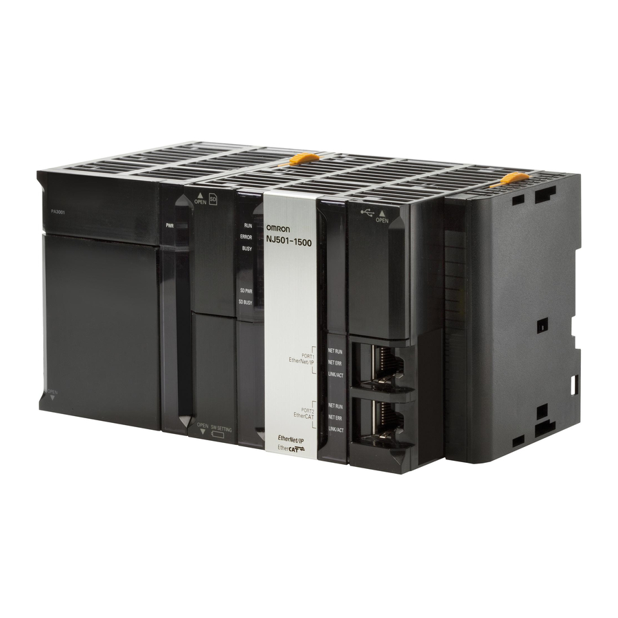
24 VDC power 24 VDC power ZW-S7030 supply supply (for Switching hub) (for Sensor Controller) Calibration ROM Manufacturer Name Model Version OMRON NJ-series CPU Unit NJ501-1500 Ver.1.10 (Built-in EtherNet/IP port) OMRON Power Supply Unit NJ-PA3001 OMRON Switching hub W4S1-05C Ver.1.0... - Page 11 5.Applicable Devices and Device Configuration Additional Information For specifications of 24 VDC power supply available for Switching hub, refer to the Switching Hub W4S1-series Users Manual (Cat. No. 0969584-7). Additional Information For specifications of 24 VDC power supply available for Sensor Controller, refer to the Displacement Sensor ZW-7000 series Confocal Fiber Type Displacement Sensor User's Manual (Cat.
-
Page 12: Ethernet/Ip Settings
6.EtherNet/IP Settings 6. EtherNet/IP Settings This section describes the setting contents of parameters, global variables, tag sets, and tag data link table that are all defined in this document. 6.1. Parameters The parameters that are set in this document are shown below. 6.1.1. -
Page 13: Data Types To Use For Tag Data Links
6.EtherNet/IP Settings 6.2. Data Types to Use for Tag Data Links The following data types are used for tag data links to communicate with Sensor Controller. ■Defining a data type for signal access (Union) Data type to access control signals and status signals Data type name Data type U_EIPFlag... -
Page 14: Global Variables
6.EtherNet/IP Settings 6.3. Global variables The Controller treats the data in tag data links as global variables. The content of global variable settings is shown below. ■Output area (Controller to Sensor Controller) Variable Data type Data size EIPOutput S_EIPOutput 24 bytes Sensor Controller data Variable name Base type... - Page 15 6.EtherNet/IP Settings ■Input area (Sensor Controller to Controller) Variable Data type Data size EIPInput S_EIPInput 56 bytes Sensor Controller data Variable name Base type Sensor Head status signal 1 EIPInput.SensorHeadStatusFlag1.F * BOOL[32] (Data type: U_EIPFlag) EIPInput.SensorHeadStatusFlag1.W DWORD EIPInput.SensorHeadStatusFlag2.F * BOOL[32] Sensor Head status signal 2 (Data type: U_EIPFlag) EIPInput.SensorHeadStatusFlag2.W...
- Page 16 6.EtherNet/IP Settings *2: Assignment of Sensor Head status signal2 Variable: EIPInput.SensorHeadStatusFlag2.F TASK TASK TASK TASK STABIL RESET HOLD STAT STAT STAT STAT GATE ENABLE LIGHT ITY1 STAT STAT ZERO ZERO ZERO ZERO PASS HIGH PASS HIGH PASS HIGH PASS HIGH STAT_ STAT_ STAT_...
-
Page 17: Tag Sets
6.EtherNet/IP Settings 6.4. Tag Sets The content of tag set settings to operate tag data links is shown below. The data in the tag sets are assigned with the following OUT No. and IN No. ■Output area (Controller to Sensor Controller) Originator variable (tag set name) Data size (byte) EIP050_OUT... -
Page 18: Ethernet/Ip Connection Procedure
7.EtherNet/IP Connection Procedure 7. EtherNet/IP Connection Procedure This section describes the procedures for connecting Sensor Controller and Controller on the EtherNet/IP network. The explanations of procedures for setting up Controller and Sensor Controller given in this document are based on the factory default settings. For the initialization, refer to Section 8. -
Page 19: Sensor Controller Setup
7.EtherNet/IP Connection Procedure 7.2. Sensor Controller Setup Set up Sensor Controller. 7.2.1. Hardware Settings Connect cables and others to Sensor Controller. Precautions for Correct Use Make sure that the power supply is OFF when you set up. Make sure that Sensor Controller is powered OFF. - Page 20 7.EtherNet/IP Connection Procedure Connect Switching hub to Personal computer and to Ethernet connector on Sensor Controller with LAN cables. LAN cable LAN cable Connect 24 VDC power supply (for Switching hub) to Switching hub. 24VDC power supply Connect 24 VDC power supply to 24 V input terminal block.
- Page 21 7.EtherNet/IP Connection Procedure 7.2.2. Parameter Settings Set the parameters for Sensor Controller. The parameters are set using Sysmac Studio. Install Sysmac Studio on Personal computer beforehand. Since Personal computer and Sensor Controller are connected with LAN cables, set the IP address of Personal computer to 192.168.250.100.
- Page 22 7.EtherNet/IP Connection Procedure Set The IP address of Personal Dialog box in (2) computer to 192.168.250.100. *The IP address can be changed in the following way. (1)Start Personal computer and log in using an administrator account. From the Windows Start menu, select Control Panel - Network and Internet - Network and Sharing Center, and click...
- Page 23 7.EtherNet/IP Connection Procedure Start Sysmac Studio. *If the User Account Control Dialog Box is displayed at start, make a selection to start Sysmac Studio. Sysmac Studio starts. Click New Project. The Project Properties Dialog Box is displayed. Select Measurement Sensor from the pull-down list of Category in the Select Device Area.
- Page 24 7.EtherNet/IP Connection Procedure The Select Sensor Dialog Box is displayed. Select Specify a sensor and set the IP address to 192.168.250.50. Click Confirm. The information of Sensor Controller and Sensor Head is displayed. Check that the information displayed there indicates the connected devices. Click OK.
- Page 25 7.EtherNet/IP Connection Procedure The Sensor Controller project is displayed online. Sensing Monitor Pane When an online connection is established, the Edit Pane is surrounded with a yellow frame. Toolbox The following panes are Multiview Edit Pane displayed in this window. Explorer Left: Multiview Explorer Center: Edit Pane...
- Page 26 7.EtherNet/IP Connection Procedure Double-click System data under Configurations and Setup - DeviceGroup - 1:ZW-7000(2.0) :Online - System in the Multiview Explorer. The System data Tab Page is displayed. Click the Ethernet communication settings Button. The Ethernet communication settings view is displayed. Select EtherNet/IP from the pull-down list of Fieldbus.
- Page 27 7.EtherNet/IP Connection Procedure Double-click 1:ZW-7000(2.0):Online under Configurations and Setup - DeviceGroup in the Multiview Explorer. The Online view is displayed on the 1:ZW-7000(2.0):Online Tab Page. Click Save settings (sensor internal memory) in the Save settings Field. The Save settings Dialog Box is displayed.
- Page 28 7.EtherNet/IP Connection Procedure Check that the Run Button in the Operation mode Field becomes dim. Click Disconnect in the Sensor connection Field. The Disconnect Dialog Box is displayed. Check the contents and click Yes. The connection goes offline, and the yellow frame surrounding the Edit Pane disappears.
-
Page 29: Controller Setup
7.EtherNet/IP Connection Procedure 7.3. Controller Setup Set up Controller. 7.3.1. IP Address Settings Set the IP address of Controller. Connect a LAN cable to the Personal CPU Unit End Cover built-in EtherNet/IP port computer Controller (PORT1) on Controller, and Switching hub connect a USB cable to the USB cable peripheral (USB) port. - Page 30 7.EtherNet/IP Connection Procedure Click Create. The New Project is displayed. The following panes are displayed in this window. Left: Multiview Explorer Toolbox Top right: Toolbox Bottom right: Controller Status Pane Middle top: Edit Pane Multiview Edit Pane The following tabs are displayed Controller Explorer Status Pane...
- Page 31 7.EtherNet/IP Connection Procedure 7.3.2. Target Device Registration Register the target device. Select EtherNet/IP Connection Settings from the Tools Menu. The EtherNet/IP Device List Tab Page is displayed in the Edit Pane. Right-click and select Edit from the menu while Built-in EtherNet/IP Port Settings is selected.
- Page 32 7.EtherNet/IP Connection Procedure Check the settings and click Add. 192.168.250.50 is registered in Target Device of the Toolbox.
- Page 33 7.EtherNet/IP Connection Procedure 7.3.3. Setting the Global Variables Set the global variables to use for tag data links. Double-click Data Types under Programming - Data in the Multiview Explorer. Click the Union Side Tab. Click on a space in the Name Column to enter a new data type.
- Page 34 7.EtherNet/IP Connection Procedure In the same way as steps 3 and 4, enter the following data in the newly added row. ・Name: W Data type: DWORD Click the Structures Side Tab. Click on a space in the Name Column to enter a new data type.
- Page 35 7.EtherNet/IP Connection Procedure After entering, right-click and select Create New Data Type from the menu. Enter S_EIPInput in the Name Column. In the same way as steps 7 and 8, enter the following data in the newly added rows. ・Name: SensorHeadStatusFlag1 Base type: U_EIPFlag ・Name:...
- Page 36 7.EtherNet/IP Connection Procedure Double-click Global Variables under Programming - Data in the Multiview Explorer. The Global Variables Tab Page is displayed in the Edit Pane. Click on a space in the Name Column to enter a new variable. Enter EIPOutput in the Name Column.
- Page 37 7.EtherNet/IP Connection Procedure Click the + Button. A row for new entry is added. Click the Down Arrow Button of the entry cell in the Variable to be refreshed Column (the left side of the figure). The variables set in the previous steps are displayed.
- Page 38 7.EtherNet/IP Connection Procedure 7.3.4. Tag Registration Register the tags and the tag sets. Click the Tag Set Button on the Built-in EtherNet/IP Port Settings Connection Settings Tab Page. Select the Input Tab in Tag Sets. Right-click any open space on the Input Tab Page and select Create New Tag Set from the menu.
- Page 39 7.EtherNet/IP Connection Procedure Select Output Tab. Right-click any open space on the Output Tab Page and select Create New Tag Set from the menu. A new name can be entered in the Tag Set Name Column. In the same way as step 3, enter EIP050_OUT.
- Page 40 7.EtherNet/IP Connection Procedure 7.3.5. Setting the Connections Set the target variables (that receive the open request) and the originator variables (that request for opening), and then set the connections (tag data link table). Click the Connection Button on the Built-in EtherNet/IP Port Settings Connection Settings Tab Page.
- Page 41 7.EtherNet/IP Connection Procedure Click the entry cell for Input in the Originator Variable Column. The pull-down list is displayed. Select the tag set name to use. Likewise, set the originator variable for Output. Set the connection type, RPI [ms], and timeout value as required.
- Page 42 7.EtherNet/IP Connection Procedure 7.3.6. Transferring the Project Data Connect online and transfer the connection settings and the project data to Controller. When you transfer a user program, configuration data, setup data, device variables, or values in memory used for CJ-series Units from Sysmac Studio, the devices or machines may perform unexpected operation regardless of the operating mode of CPU Unit.
- Page 43 7.EtherNet/IP Connection Procedure Select Communications Setup from the Controller Menu. The Communications Setup Dialog Box is displayed. Check that the Direct connection via USB Option is selected in Connection type. Click OK. Select Online from the Controller Menu. A confirmation dialog box is displayed.
- Page 44 7.EtherNet/IP Connection Procedure Select Synchronize from the Controller Menu. The Synchronization Dialog Box is displayed. Check that the data to transfer (NJ501 in the right dialog box) is selected. Uncheck Do not transfer the EtherNet/IP connection settings (i.e., tag data link settings). Click Transfer To Controller.
- Page 45 7.EtherNet/IP Connection Procedure Check that the synchronized data is displayed with the color specified by "Synchronized" and that a message is displayed stating "The synchronization process successfully finished". Confirm that there is no problem, and click Close. *A message stating "The synchronization process successfully finished"...
-
Page 46: Ethernet/Ip Communication Status Check
7.EtherNet/IP Connection Procedure 7.4. EtherNet/IP Communication Status Check Confirm that the EtherNet/IP tag data links operate normally. 7.4.1. Checking the Connection Status Check the connection status of the EtherNet/IP network. Check with LED indicators on Controller that the tag data links operate normally. - Page 47 7.EtherNet/IP Connection Procedure Select the Connection Status Tab. Check that a blue circle is displayed next to the applicable connection listed in the Connection Name Column. Check that the Status is 00:0000. Select the Tag Status Tab. Check that all the tags in the Tag Name Column are displayed and that blue circles are displayed next to them.
- Page 48 7.EtherNet/IP Connection Procedure 7.4.2. Checking the Sent and Received Data Check that the correct data are sent and received. In this document, the system data acquisition command and the number of digits displayed past decimal point for command parameters are set to global variables in the output area where Controller is output to Sensor Controller, and response data (the number of digits displayed past decimal point) from Sensor Controller are checked, which are stored in global variables in the input area.
- Page 49 7.EtherNet/IP Connection Procedure Enter 0040 4000 for EIPOutput.CommandCode in the Modify Column. 0040 4000 is displayed for EIPOutput.CommandCode in the Online value Column. *The command code 0040 4000 (system data acquisition) is set. In the same way as step 5, set 900 for EIPOutput.Command Param1 in the Online value Column.
- Page 50 7.EtherNet/IP Connection Procedure Additional Information For details on commands, refer to 4-1 EtherNet/IP Connection of the Displacement Sensor ZW-7000 series Confocal Fiber Type Displacement Sensor User's Manual for Communications Settings (Cat. No. Z363). Additional Information For details on system data, refer to 8-2 System data list of the Displacement Sensor ZW-7000 series Confocal Fiber Type Displacement Sensor User's Manual for Communications Settings (Cat.
-
Page 51: Initialization Method
8.Initialization method 8. Initialization method The setting procedures in this document are based on the factory default settings. Some settings may not be applicable unless you use the devices with the factory default settings. 8.1. Initializing Controller To initialize the Controller settings, it is necessary to initialize CPU Unit. Change the operating mode of Controller to PROGRAM mode and select Clear All Memory from the Controller Menu in Sysmac Studio. -
Page 52: Appendix: Procedure Using The Project File
9. Appendix: Procedure Using the Project File This section describes the procedure in which you use the following project file. The project file includes the setting contents described in 7.3. Controller Setup. Obtain the project file with a latest version from OMRON Corporation. Name File name... -
Page 53: Controller Setup
The Import file Dialog Box is displayed, Select P653_NJ_EIP_OMRON_ZW-70 00_EV100.csm2 (project file) and click Open. *Obtain the project file from OMRON. The dialog box on the right is displayed. Check the contents and click No. The P653_NJ_EIP_OMRON_ ZW-7000_EV100 project is displayed. - Page 54 9.Appendix: Procedure Using the Project File Select Change Device from the Controller Menu. The Change Device Dialog Box is displayed. Check that the Device and the Version Fields are set as shown on the right. Click Cancel. *If the settings are different, select the setting items from the pull-down list, and click OK.
-
Page 55: Revision History
10.Revision History 10. Revision History Revision Date of revision Description of revision code June 24, 2016 First edition... - Page 56 2016 P653-E1-01 0616-(-)
Need help?
Do you have a question about the sysmac NJ Series and is the answer not in the manual?
Questions and answers