
Related Manuals for Omron ZW-C1*AT


Summary of Contents for Omron ZW-C1*AT
- Page 1 Displacement Sensor ZW series Confocal Fiber Type Displacement Sensor User’s Manual ZW-CE1@T Z332-E1-07...
- Page 2 Introduction Thank you for purchasing the ZW. This manual provides information regarding functions, performance and operating methods that are required for using the ZW. When using the ZW, be sure to observe the following: • The ZW must be operated by personnel knowledgeable in electrical engineering. •...
- Page 3 Terms and Conditions Agreement (Please Read) Basic configuration User's Manual Installation and Connections Basic Operation Settings for Function Convenient Functions Communications with External Devices Offline Settings Troubleshooting Sensor controller operations APPENDICES Confocal Fiber Type Displacement Sensor...
- Page 4 Omron's exclusive warranty is that the Products will be free from defects in materials and workmanship for a period of twelve months from the date of sale by Omron (or such other period expressed in writing by Omron). Omron disclaims all other warranties, express or implied.
- Page 5 Omron Companies shall not be responsible for conformity with any standards, codes or regulations which apply to the combination of the Product in the Buyer’s application or use of the Product. At Buyer’s request, Omron will provide applicable third party certification documents identifying ratings and limitations of use which apply to the Product.
- Page 6 Recommended power supply: S8VS-06024 (Omron, DC24 V 2.5 A 60 W) • The supply voltage must be within the rated range (DC24 V ± 10 %).
- Page 7 • Whenever any trouble, including, strange odor smelled, the body overheated or smoke escaped, was found, immediately stop the operation, and consult an OMRON branch or sales office with the system shut down. • Do not drop or make a strong impact on the unit.
- Page 8 Precautions for Correct Use Please observe the following precautions to prevent failure to operate, malfunctions, or undesirable effects on product performance. 1. Installation Site Do not install the product in locations subjected to the following conditions: • Ambient temperature outside the rating •...
-
Page 9: Editor's Note
Indicates pages where related information can be found. Indicates that the setting is optional in a configuration procedure. Optional Copyrights and Trademarks • Sysmac is a trademark or registered trademark of OMRON corporation in Japan and other countries for our FA equipment products. ZW User's Manual... -
Page 10: Notice
• Every effort has been made to ensure the accuracy of the contents of this manual, but if you should notice any mistake, questionable section, or the like in this manual, please contact an OMRON branch or sales office. • If you do so, please also tell us the manual number, which is found at the end of the manual. -
Page 11: Table Of Contents
Table of Contents Editor's Note ........... . 7 Copyrights and Trademarks . - Page 12 Entering project information ........55 3-2 Explanation of Screen Sections .
- Page 13 Checking Information ......... . . 114 Making Sensor Settings .
- Page 14 Sample Ladder Program (EtherNet/IP) ......225 6-4 No-protocol Connection ........226 Outline of No-protocol Communications .
- Page 15 9-8 Setting the Output Conditions ......310 Setting the Filter ..........310 Setting Scaling .
- Page 16 10-2 Firmware update ........380 Use PC tools (Sysmac Studio) to update.
- Page 17 ZW User's Manual...
-
Page 18: Search From Settings
Search from Settings Settings Set by Sysmac Studio Set by Sensor Controller Setting the Material for the Target to Measure p.75 p.302 Setting Exposure Time Control Mode p.79 p.304 Measuring the Height p.83 p.305 Measuring the Thickness p.85 p.306 Calculating p.86 p.307 Setting the Filter... -
Page 19: Basic Configuration
Basic configuration 1-1 ZW-series Displacement Sensors ......18 1-2 Basic Operation Flow........19... -
Page 20: Zw-Series Displacement Sensors
1-1 ZW-series Displacement Sensors The ZW-series is a line of fiber coaxial displacement sensors. They consist of Sensor Head and Sensor Controller, calibration ROM, and exclusive setting PC tool which runs on personal computers for system settings and monitoring. Sensor head Sensor Controller PC tool Detects a target to... -
Page 21: Basic Operation Flow
1-2 Basic Operation Flow The following is the basic operation flow for ZW Series. Installation and connection Section 2 Installation and Connections Install the sensor head. Preparation for measurement Default settings for connecting Section 2 Installation and Connections the sensor head. Perform a sensor head calibration. - Page 22 Section 3 Basic Operation Setting Threshold Value 3-6 Setting Threshold Value Functions used Switching Banks 3-4 Bank Switching during operation Executing Zero Reset 3-5 Perform the Zero Reset Section 6 Communications with External Devices Setting I/O (analog/judgment) 6-1 Parallel I/O connection Using EtherCAT Communications 6-2 EtherCAT Connection 6-3 Ethernet/IP Connection...
-
Page 23: Installation And Connections
Installation and Connections 2-1 System Configuration ........22 2-2 Part Names and Functions . -
Page 24: System Configuration
2-1 System Configuration System Configuration Connecting with EtherCAT EtherCAT Master (*1) Sysmac Studio (when the master is NJ Series) Standard Edition NJ-series Machine Automation Controller General-purpose USB Cable General-purpose Ethernet Cable Special EtherCAT Cable (RJ45/RJ45) ZW-CE1@T I/O control PLC Other EtherCAT slaves 24-V Trigger input power supply... -
Page 25: Connection Compatibility
Connection Compatibility Connected to Other connection ZW-CE1@T EtherCAT EtherNet/IP Ethernet RS-232C I/O Cable (no-protocol) (no-protocol) EtherCAT Not compatible Compatible Compatible Compatible EtherNet/IP Not compatible Compatible Compatible Compatible Ethernet Compatible Compatible Compatible Compatible (no-protocol) Ethernet Compatible Compatible Compatible Compatible (programmable no- protocol) Important •... - Page 26 Product Model Application EtherCAT Junction Slave • GX-JC03 Used to connect multiple sensors or PLCs using EtherCAT. (3 ports type) • GX-JC06 (6 ports type) System Configuration ZW User's Manual...
-
Page 27: Part Names And Functions
2-2 Part Names and Functions The following describes the names and functions of parts of the Sensor Head, Calibration ROM and Sensor Controller. Sensor Head Straight type Right angle type Names Functions Projector/receiver Projects and receives light. Serial number. Serial number. Only a calibration ROM with the same serial number is available. -
Page 28: Sensor Controller
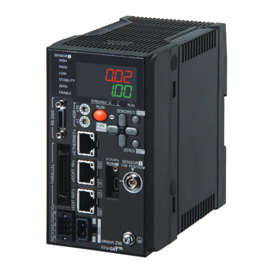
Sensor Controller <Front view> <Rear view> Display Control Panel Connectors/ terminals <Bottom view> Part Names and Functions ZW User's Manual... -
Page 29: Front View
Front view ● Display Names (light color) Functions HIGH indicator (orange) The HIGH indicator is lit while judgment is resulted in HIGH (HIGH threshold value < measured value). The PASS indicator is lit while judgment is resulted in PASS (LOW threshold value PASS indicator (green) measured value ... -
Page 30: Rear View
• RJ45 connector (8-pin modular jack) • For one-to-one connection: Select cross cable. • For connection through an industrial switching hub: Select straight cable. (Recommended hub: W4S1-0@ (Omron)) EtherCAT input connector This connector is used to connect to EtherCAT-compatible devices. - Page 31 Detailed LED specifications are given below. LED name Color Status Contents ECAT RUN indicator Green Initialization status Blinking Pre-Operational status Single flash Safe-Operational status Operational status ECAT ERROR indicator No error Blinking Communication setting error or PDO mapping error Single flash Synchronization error or communications data error Double flash Application WDT timeout...
-
Page 32: Installation
2-3 Installation Installation of Sensor Head Installation procedure Place the Sensor Head with an appropriate distance from the target to measure, fixing it by tightening four M3 screw inserted into their respective installation holes. Tightening torque: 0.54 N • m 10-1 Specifications and External Dimensions p.358 M3 screw×4 Important... - Page 33 Measuring range With the ZW series, the measurement center distance is expressed as 0 with the NEAR side as + and the FAR side as -. Straight type ZW-S07 ZW-S20 NEAR side: +0.3 mm Measurement center Measuring NEAR side: +1 mm Measurement center distance: 7 mm center: 0 mm...
- Page 34 Right angle type ZW-SR07 ZW-SR20 Measurement center Measurement center distance: 7 mm distance: 20 mm NEAR side: +0.3 mm NEAR side: +1 mm Measuring Measuring center: 0 mm Measuring center: 0 mm FAR side: -0.3 mm Measuring range range FAR side: -1 mm ZW-SR40 Measurement center distance: 40 mm...
- Page 35 Mutual interference When using two or more Sensor Heads next to each other, mutual interference will not occur if other beam spots are outside the ■ areas in the following diagrams. Straight type ZW-S07 ZW-S20 6.7 mm 0.6 mm 19 mm 1.6 mm 2 mm 3.0 mm...
- Page 36 Right angle type ZW-SR07 ZW-SR20 6.7 mm 0.6 mm 19 mm 1.6 mm 2 mm 3.0 mm ZW-SR40 34 mm 12 mm 6.0 mm Installation ZW User's Manual...
-
Page 37: Installation Of Sensor Controller
Installation of Sensor Controller Precautions for installation Install the Sensor Controller in the orientation indicated by the circle mark in the following figure. Do not install it laying on its side or upside down. For adequate intake and/or exhaust, keep the Sensor Controller clear by 30 mm or more on its top, and by 10 mm or more from either side. - Page 38 Installing on the DIN track The following describes how to attach the Sensor Controller on a 35 mm-wide DIN track. DIN track (option) PFP-100N (1 m) PFP-50N (0.5 m) PFP-100N2 (1 m) End plate (option) PFP-M Installation procedure Hook the upper edge of the Sensor Controller's back slot onto the upper edge of the DIN track.
-
Page 39: Connecting Calibration Rom
Installing on bottom The following describes how to attach the Sensor Controller on its bottom. Drill four installation holes on the base. Important For the location installation holes, see the external dimensions. 10-1 Specifications and External Dimensions p.358 Tighten four M4 screws to fix the Sensor Controller on the base. -
Page 40: Connecting Fiber Cable
Connecting Fiber Cable Connect the fiber cable on the Sensor Head to the Sensor Head connector on the Sensor Controller as follows: Remove the protective caps from the Sensor Controller's fiber connector and the fiber cable. Protective cap Fiber cable Protective cap Fiber connector Important... - Page 41 Important • Handling fiber cables Use them in compliance with the following. -Fiber cable bend radiuses must be at least 20 mm. -Do not let bending cause stress at the connecting section of a fiber connector. -Do not yank hard on a fiber cable. -Do not step on a fiber cable or place anything heavy on it.
- Page 42 Extending fiber cable To extend the fiber cable on the Sensor Head, use an extension fiber cable and connecting adapter. Connection adapter ZW-XFC Sensor Head Extension fiber cable fiber cable ZW-XF@@R: (2 m/5 m/10 m/20 m/30 m) Mate the convex section on the fiber cable with the groove on the connection adapter and turn the threaded section clockwise while pushing in.
- Page 43 Important • The connection adapter (ZW-XFC) comes packed together with the extension fiber cable (ZW-XF@@R). • Never use any extension fiber cable and/or connecting adapter other than those specified in the above. • Hold the combined length of the normal and extension fiber cables to no more than 32 m. •...
-
Page 44: Calibrating Sensor Head
Calibrating Sensor Head Calibrate the Sensor Head by obtaining the dark data in the no-incoming light status. • When removing and inserting a fiber cable from/to the Sensor Controller (Including the initial connection). • When extending a fiber cable. The calibration data is stored inside the Sensor Controller. Therefore, if the sensor head is calibrated once, as long as the fiber connection state does not change (if it is not disconnected from or connected to the Sensor Controller or an extension added), this operation is not needed each time. - Page 45 Important When Sensor Head calibration fails If the Sensor Head is calibrated in an inappropriate environment, an error is displayed on the main display. If this happens, chack the environment and try again. If an error continues even after calibrating the Sensor Head in an appropriate environment, the fiber connector on the Sensor Head or Sensor Controller may be stained.
-
Page 46: Wiring
2-4 Wiring 32-pole extension connector Used for judgment output, control input, etc. Compatible connector: FX2B series (Hirose Electric Co., Ltd.) A parallel cable (ZW-XCP2E) for an extension connector with 2 m cable is included. (*1 ) (*2 ) (*1 ) Color Signal name Signal name... - Page 47 Class Name Description Parallel HIGH output This outputs judgment results - HIGH (HIGH threshold values < Measured value). output This outputs judgment results - PASS (LOW threshold values Measured value HIGH PASS output threshold values). LOW output This outputs judgment results - LOW (LOW threshold values > Measured value). ALARM output This turns ON when there is a system error.
-
Page 48: Analog Output Terminal Block
Analog output terminal block Used for analog output. Compatible cable specifications: AWG 18 to 28, pin processed length: 7 mm Signal name Signal name OUT1(V) OUT1(A) OUT1 0V Important Cut the unnecessary signal lines so that they do not touch other signal lines. The length of Cables should be less than 30 m. -
Page 49: Input Terminal Block
Push in and hold the release button next to the terminal hole using a screwdriver while pushing the wire fully into the terminal hole and remove the screwdriver. After the connection has been established, pull the wire gently, to make sure that the connection has been made Release button securely. - Page 50 Remove 24 V input terminal block from the Sensor Controller. Push in and hold the release button next to the terminal hole using a screwdriver while pushing the wire fully into the terminal hole and remove the Release button Terminal hole screwdriver.
-
Page 51: Electrical Specifications
Electrical Specifications Input circuit Item Specifications Model ZW-CE10T ZW-CE15T Input type Input voltage DC24 V10 % (21.6 to 26.4 V) DC24 V10 % (21.6 to 26.4 V) Input current 7 mA Typ. (DC24 V) 7 mA Typ. (DC24 V) ON voltage/ON current 19 V min./3 mA min. - Page 52 Output circuit Item Specifications Model ZW-CE10T ZW-CE15T Output type Output voltage DC21.6 to 30 V DC21.6 to 30 V Load current 50 mA max. 50 mA max. ON residual voltage 1.2 V max. 1.2 V max. ON leakage current 0.1 mA max. 0.1 mA max.
-
Page 53: Installing The Sysmac Studio
2-5 Installing the Sysmac Studio The PC Tool used to set up ZW-series Displacement Sensors is installed from the Sysmac Studio Installer. Refer to the Sysmac Studio Version 1 Operation Manual (Cat. No. W504) for the system requirements and installation procedure. ZW User's Manual Installing the Sysmac Studio... - Page 54 MEMO Installing the Sysmac Studio ZW User's Manual...
-
Page 55: Basic Operation
Basic Operation 3-1 Launching a project ........54 3-2 Explanation of Screen Sections . -
Page 56: Launching A Project
3-1 Launching a project Connecting to the sensor with PC tool Creating a new project Create a new project, add a sensor to the project, then start communicating with the sensor. Start up the PC tool. Create a new project. Click [New Project] and select [Displacement Sensor] from [Category] under [Select Device], and [ZW] from [Device]. -
Page 57: Entering Project Information
After the sensor is connected, the following window appears. The Main pane appears on the Edit pane. The sensor starts up in RUN mode. Adding a sensor to a project After the project is created, additional sensors can be added to the project. ... -
Page 58: Explanation Of Screen Sections
3-2 Explanation of Screen Sections PC tool The following summarizes the names and functions of the window sections of Sysmac Studio. Sysmac Studio Main window Name Description Menu bar Menu items that can be used with this tool is displayed. Toolbar Tool functions that can be used with this tool is displayed with icons. - Page 59 Explorer pane Name Description Sensor model Displays the sensor model. Displays online/offline status at the end. Bank group This is a group of bank data. Bank data can be registered up to 8 in NORMAL mode, and up to 32 in JUDGMENT VALUE BANK mode. Bank data This is used to set functions to perform measurements.
- Page 60 Edit pane The Edit Pane changes as shown below based on what is selected in the Explorer Pane. Main pane Bank data edit pane System data setting pane Name Description Menu icon Parameters to be edited on each edit pane can be changed. Setting item When editing each menu item selected with menu icons, a pop up window is called out.
- Page 61 List of icons (1) Menu icon Edit pane type Icon Menu name Description Main pane General settings Sensor name and project information can be checked. Online Switching between online and offline connections with the actual sensors, and switching the operating mode can be performed. Also, the internal logging process, saving set data, monitoring the measurement results can be performed.
- Page 62 (2) Operation icons Bank data edit pane Icon Name Description Zoom in Zoom in the line bright. Zoom out Zoom out the line bright. Fit to frame Change the size of the line bright so it fits the window size. Export Saves the line bright being displayed.
-
Page 63: Switching Operation Modes
3-3 Switching operation modes The Sensor Controller has two operation modes. One is RUN mode and the other is FUN mode. Switch to the desired mode depending on purpose. (The Sensor Controller always starts up in the RUN mode when the power is turned on.) Item Setting item Mode... -
Page 64: Bank Switching
3-4 Bank switching Multi-task and Bank Data Multi-task Function With the ZW Series, you can set multiple measurement processing for one sensing setting. This measurement processing is called a "task (TASK)." Example: When measuring height and side run-out at the same time Surface fluctuation (TASK2) Height (TASK1) For tasks, TASK1 to TASK4 are available for registration. - Page 65 Bank Data ZW series can hold up to eight sets of sensing settings, which are called "bank (BANK)". When the setup is changed, the bank can be switched externally. What is Bank? The sensing settings for measurement are held as one bank. Sensing Sensing Filter...
-
Page 66: Switching Banks
Switching Banks Switches banks. Click the bank group on the Explorer pane to open. Select the bank data to switch and double click or right click it to select the Edit menu. The bank in the Bank data edit pane that is active on the Edit pane becomes the current bank. -
Page 67: Perform The Zero Reset
3-5 Perform the Zero Reset Zero reset What is Zero Reset? This function allows resetting the measured value to "0" at any timing during measurement in the RUN mode. The measured value can be displayed and output as a positive or negative deviation (tolerance) from the set reference value "0". - Page 68 Example 3: Measure the level difference of the sensing object (execute zero reset at every measurement) Sensor head This step is measured. Zero reset Zero reset Zero reset executed executed executed Direction of movement The zero reset function also allows setting the reference value to the hold value for a hold measurement or any value other than zero.
- Page 69 Important • When a zero reset is executed, the analog output becomes the voltage or current value at the center of the two preset points. Analog output becomes roughly 0 V or 12 mA when focus is not set. Setting Monitor Focus p.142 •...
-
Page 70: Setting Threshold Value
3-6 Setting Threshold Value Threshold Value Settings Switch the Sensor Controller to the FUN mode and set the range in order for the measured value to be judged as PASS. Both HIGH and LOW threshold values are set. As a judgment result, HIGH, PASS or LOW is output. HIGH threshold value Measured value LOW threshold value... - Page 71 Item Setting item Setting value Description Judgment LOW threshold - 999.999999 to 0 (default value) to Set the lower limit (LOW) threshold value. 999.999999 [mm] HIGH threshold - 999.999999 to 0 (default value) to Set the upper limit (HIGH) threshold value. 999.999999 [mm] ...
-
Page 72: Saving A Project
3-7 Saving a project Saving a project Save the project being edited with the PC tool. The project to be saved has the following information. Configuration data Description Project information Information on the sensor registered in this project. Entire sensor information Entire sensor information. -
Page 73: Operating With Sensor Controller
3-8 Operating with Sensor Controller Other than using PC tools, ZW Series can also be operated using the operation keys on the Sensor Controller. For details on how to operate with operation keys, see 9. Sensor controller operations. ZW User's Manual Operating with Sensor Controller... - Page 74 MEMO Operating with Sensor Controller ZW User's Manual...
-
Page 75: Settings For Function
Settings for Function 4-1 Setting Sensing ......... . . 74 4-2 Setting Measurement Items. -
Page 76: Setting Sensing
4-1 Setting Sensing Selecting the Area Mode Area modes can be used selectively according to the target to measure. Item Setting item Setting value Description Operating mode Area Mode 1 area mode Usually, select this setting. 2 area mode We recommend measuring in the 2 area mode when the measurement object is a transparent object and the reflection characteristics of the target to measure are different. -
Page 77: Setting The Material Of The Target To Measure
Setting the Material of the Target to Measure Setting the material of the target to measure. Item Setting item Setting value Description Operation mode Material Normal (default value) A measurement can be performed at specific linearity regardless of the type of target to measure. Usually, select this setting. -
Page 78: Setting The Noise Cut Level
Setting the Noise Cut Level The setting a larger value than the noise level, the noise can be cut. Noise can be cut. Noise Item Setting item Setting value Description Operation mode Noise cut level 0 to 4,095 [Gradation] Set the number of gradations when noise is cut from the (Default value :100) line bright. -
Page 79: Setting Smoothing Size
Setting Smoothing Size When two measurement surfaces are close, the line bright may not be divided. The setting of smoothing size a smaller value, it becomes easy to divide. Smoothing size : 5 Smoothing size : 1 Item Setting item Setting value Description Operation mode Smoothing size... -
Page 80: Setting Start Direction Of Count Measurement Surfaces
Setting Start Direction of Count Measurement Surfaces When a number of measurement surfaces exists, start direction can be selected from NEAR side or FAR side. Example: NEAR Example: FAR 1 surface 4 surface 2 surface 3 surface 3 surface 2 surface 4 surface 1 surface Item... -
Page 81: Setting Exposure Time Control Mode
Setting Exposure Time Control Mode Set the exposure time control mode and exposure time (maximum) or exposure time (fixed). Item Setting item Setting value Description Exposure time Exposure mode Auto (default value) Automatically sets the exposure time within the range that does not exceed the specified upper limit. -
Page 82: Setting The Measurement Area
Setting the Measurement Area The measurement area can be limited, setting upper line and lower line of selected area. The measurement object can be measured stabile, cutting out the area that the object does not exist. When the measurement object is set to "Glass," measurement may not be performed correctly as measurement will be influenced by reflection from the rear surface. - Page 83 Automatically Following the Range of Measurement Area2 When 2 area mode is set, the measurement area 2 can be set automatically to measure the measurement surface (Follow) , and the measurement area 2 range can be follow the measurement surface (Base) movement.
- Page 84 Set [Area follow]. Set [Reference surface] and [Following surface]. Click [Area Teach]. The range applied to measure the measurement surface (Follow) is automatically set as the measurement area 2. Setting Sensing ZW User's Manual...
-
Page 85: Setting Measurement Items
4-2 Setting Measurement Items What is a Measurement Item? Obtain the waveform data based on the specified sensing condition, and calculate the height/thickness of up to four surfaces included in the measuring range. Perform calculations using the output result of each task. Count the measurement surface closest to the Sensor Head first. - Page 86 Item Setting item Setting value Description Height settings Measurement Area 1 (default value)/Area 2 The area targeted for measurement can be switched. area Measurement Edge1/Edge2/Edge3/Edge4/ The measurement surface targeted for measurement can surface peak (default value) be switched. The peak is the surface of all measurement surfaces having the highest received light amount.
-
Page 87: Measuring The Thickness
Measuring the Thickness If you have glass of known thickness, scaling can be adjusted referenced to that glass so that transparent objects can be measured more easily. Sensor head Transparent object Edge 1st Thickness Edge 2nd Item Setting item Setting value Description Thickness Measurement... -
Page 88: Performing Calculations
Performing Calculations Perform calculations using the results calculated by the tasks. The calculation formula is mX+nY+K. Item Setting item Setting value Description Calculation Parameter X OFF (default value)/TASK1 to TASK4 The task to be calculated can be switched. Parameter Y OFF (default value)/TASK1 to TASK4 The task to be calculated can be switched. -
Page 89: Setting The Output Conditions
4-3 Setting the Output Conditions Setting Scaling This setting is used when you want to correct any errors that are generated due to the installation status of the Sensor Head, and display the corrected value on the main display as a measured value. There are three types of setting: "auto scaling"... - Page 90 Explorer pane : [Bank] | [(Bank Data Name)] (double click) Edit pane : [Task Settings] icon ( Task Settings window : [Scaling] Select [Scaling]. Enter the correction value to [Span] and [Offset]. Note Fixed scaling can also be executed by the operating keys on the Sensor Controller. Performing Manual Scaling p.314 Automatically Setting Scaling Performing 1-point Scaling...
- Page 91 Explorer pane : [Bank] | [(Bank Data Name)] (double click) Edit pane : [Task Settings] icon ( Task Settings window : [Scaling] Select [Scaling] ON. Click [Auto setting]. The [Scaling] popup menu appears. Select [Actual scaling (one point)], and click [Next >].
- Page 92 Performing 2-point Scaling Measurement is performed at two positions, and offset values are set for those measured values. Example: When correcting display values to match actual distances Display value (mm) Point 2 -3.0 Measured value (mm) -2.8 -3.0 Point 1 Item Setting item Setting value...
- Page 93 Select [Actual scaling (two points)], and click [Next >]. The [Scaling] popup menu display changes to [1st point settings]. Set correction of the 1st point. Click [STOP] to fix the [Current value], set [Set value] and click [Next >]. The [Scaling] popup menu display changes to [2nd point settings].
- Page 94 Performing Thickness Scaling The thickness is measured at one position and offset values are set for that measured value. Item Setting item Setting value Description Thickness scaling Setting value -999.999999 to 999.999999 [mm] Correct the measured value, and set the value to display. ...
-
Page 95: Setting Filters
Setting Filters Set the filter condition when filtering information obtained from the sensor before output. The following types of filters can be set depending on purpose. Displacement Waveform when Smooth filter is not set Spike-like changes are Median filter removed. [MEDIAN] Changes are smoothed Average filter... - Page 96 Setting the Median Filter The intermediate value of multiple sets of data can be output as the measurement result. Item Setting item Setting value Description Medial filter Filter mode Median filter is not used. (default value) Outputs the intermediate value of the last three measurements. Middle Outputs the intermediate value of the latest nine measurements.
- Page 97 Setting the Average Filter Output measured data as the average value of a preset count. Set this, for example, to ignore sudden changes in measured value. Item Setting item Setting value Description Average number Average 1/2/4/8/16/32/64/128/ Switches the average count. of times 256 (default value)/512/ 1024/2048/4096 [times]...
- Page 98 Setting the Frequency Filter Set a filter to ignore or detect the changes in a specific frequency in the measured data. Item Setting item Setting value Description Frequency filter Frequency filter OFF (default value) Frequency filter is not used. Lowpass filter Ignores frequency components larger than the specified cut-off frequency.
- Page 99 Setting the Differentiation Filter Set this filter to detect sudden changes in measured values occurring within an extremely short time. The differentiation filter detects changes in the measured value and current value before a comparison interval. The time of this comparison interval is defined as the differential cycle. (Default value: OFF) Item Setting item Setting value...
-
Page 100: Setting Hold
Setting Hold Set the hold conditions of the measured value. The hold function holds (retain) any value from the measured values during the specific time (sampling period), such as the maximum or minimum value. Setting the Hold Mode Set the hold mode of the measured value. Item Setting item Setting value... - Page 101 Item Setting item Setting value Description Hold Hold mode Auto Peak to Holds the difference between the maximum and minimum values of the Peak measurement result. The output changes every time the maximum or the minimum value is updated. Output (Max.value - Min.value) Current measured value...
- Page 102 Hold clearing conditions Held values can be cleared by the following operation. • When FUN (adjustment) mode/RUN (operation) mode is switched • When hold RESET is entered (32-pole extension connector, key) • Hold RESET command is entered. (Example) Peak The mode is switched between the FUN mode and RUN mode FUN mode RUN mode...
- Page 103 Setting Triggers Set how measurement start to end timing is to be input. Item Setting item Setting value Description Trigger Trigger method External input Enter the trigger for the start of sampling in "TIMING input" for the 32-pole Set- terminal block. tings The period that the signal input to "TIMING input"...
- Page 104 Explorer pane : [Bank] | [(Bank Data Name)] (double click) Edit pane : [Task Settings] icon ( Task Settings window : [Hold] Set the hold mode. Setting the Hold Mode p.98 Select the trigger method from [Trigger settings] - [Trigger method].
- Page 105 Performing Hold with a Key Input The TIMING/RESET inputs can be held on the Sensor Controller by setting as follows. Item Setting item Setting value Description Sensor settings Timing/Reset key input OFF (default value)/ON Enables TIMING and RESET key inputs from the Sensor Controller.
- Page 106 Setting a Trigger Delay Set this to ignore measure values following TIMING input to avoid the influence of bounding or mechanical vibration when a device is started up. The delay time (the delay between timing input and the start of sampling) and the sampling time can be set. TIMING input Delay time Sampling time...
-
Page 107: Setting The Zero Reset
Setting the Zero Reset Setting the Status Set enable/disable of the zero reset function. Important The status is set for each task. Explorer pane : [Bank] | [(Bank Data Name)] (double click) Edit pane : [Task Settings] icon ( ... - Page 108 Setting the Offset Set this item to set the reference value by a zero reset to a value other than zero. Item Setting item Setting value Description Zero reset Offset -999.999999 to 999.999999 [mm] Set the offset value. (default value: 0) ...
- Page 109 Setting the Zero Reset Type Set the zero reset type. Item Setting item Setting value Description Zero reset Zero reset type Real value Sets the measured value when a zero reset is executed to zero. Sensor head Measurement of height from reference surface Reference A Zero reset...
- Page 110 Setting the Zero Reset Memory Select whether or not to hold the measured value zero reset level even if the power is turned OFF. As shown in the figure below, use the zero reset memory still set to "OFF" when using this function to perform a zero reset at each measurement.
- Page 111 Set the operating mode to the FUN mode. 3-3 Switching operation modes p.61 Explorer pane : [System] (double-click) Edit pane : [Sensor Settings] icon ( Select ON/OFF from [Zero-Reset Memory mode]. Note The zero reset mode can also be set by the operating keys on the Sensor Controller. Setting the Zero Reset Memory p.325 ZW User's Manual Setting the Output Conditions...
-
Page 112: Setting The Banks
4-4 Setting the Banks Changing the Bank Mode Select the bank contents to be obtained from the settings or judgment value. Item Setting item Setting value Description Sensor settings Bank mode Normal (default Sensing setting, measurement setting and I/O setting that are set in the FUN value) (adjustment) mode are regarded as bank data. -
Page 113: Copying The Bank/System Settings
Copying the Bank/System Settings Copy the selected bank setting to another bank. Also, copy ZW system settings to a different ZW. Set the operating mode to the FUN mode. 3-3 Switching operation modes p.61 Copy the bank data or system data. Select the copy source bank data or system data from the explorer pane, and select [Copy] from the right-click menu. -
Page 114: Saving The Bank/System Settings
Saving the Bank/System Settings Save the bank/system settings to the Sensor Controller. Important • The settings of all banks are saved regardless of the currently selected bank number. • After you have made or changed settings, be sure to save the setup data. All settings will be deleted if you turn the power OFF without saving the data. -
Page 115: Clearing The Bank Settings
Clearing the Bank Settings Select a bank and initialize its settings. Set the operating mode to the FUN mode. 3-3 Switching operation modes p.61 Select the bank data. Select the bank data from the explorer pane, and select [Initialize] from the right-click menu. Note The bank settings can also be cleared by the operating keys on the Sensor Controller. -
Page 116: Setting The System
4-5 Setting the System Display/set the system environment. Checking Information Displays the information of the Sensor Controller and Sensor Head. Item Displayed item Setting value Description General settings Sensor Name Displays the name of the Sensor Controller information Sensor controller model Displays the model information of the Sensor Controller. -
Page 117: Making Sensor Settings
Making Sensor Settings Setting the Key Lock This function disables all key inputs on the Sensor Controller. Once the key lock is set, no key input will be accepted until the lock is released. This function is useful for preventing inadvertent changes to settings. Item Displayed item Setting value... -
Page 118: Initializing Settings
Setting the Number of Digits Displayed Past the Decimal Point Set the number of digits displayed past the decimal point for when numerical values are displayed on the main display and sub-display of the Sensor Controller. Item Setting item Setting value Description Sensor settings The number of decimal... - Page 119 Note • Settings can also be initialized by selecting and right-clicking a [(ZW model)] option from the explorer pane and selecting "Initialize sensor" from the right-click menu. • Settings can also be initialized by the operating keys on the Sensor Controller. Initializing Settings p.337 ZW User's Manual Setting the System...
- Page 120 MEMO Setting the System ZW User's Manual...
- Page 121 Convenient Functions 5-1 Displaying measured values in graphs ..... . . 120 5-2 Saving measured values in a file ......125 5-3 Displaying saved measured values .
-
Page 122: Displaying Measured Values In Graphs
5-1 Displaying measured values in graphs The measured values can be displayed in graphs. Important This function can only be used with project of the displacement sensor (ZW). With project of the controller (NJ), you can use the "Data trace" function to display graphs of measured values. ... - Page 123 Select data to monitor the trend for. Set data to monitor the trend for. The types of data that can be set are as follows. Item Setting item Description Target data TASK1 TASK1 measurement results TASK2 TASK2 measurement results TASK3 TASK3 measurement results TASK4 TASK4 measurement results...
-
Page 124: Specifying The Sampling Start And End Conditions
Specifying the sampling start and end conditions You can specify the conditions for starting and ending sampling. Check the Trigger start conditions/Trigger end conditions checkbox. Select the trigger condition. Item Setting item Range Description Sampling setting Trigger start Input and output Specify parallel I/O (TIMING, ZERO, BUSY, ENABLE, conditions HIGH, PASS, LOW) as the trigger condition. - Page 125 Set the trigger condition. • When the trigger target is "Data slope" Item Setting item Range Description Trigger condition Condition When the measurement results are the same value as the judgment value, the trigger condition is considered to have been met. ...
-
Page 126: Starting And Ending Sampling Before And After The Trigger Condition Is Met
Starting and ending sampling before and after the trigger condition is met You can adjust how long to start or end the sampling before or after the condition for starting and ending sampling is met. Measurement value Measurement data satisfied the start condition trigger Sampling interval Sampling start position A Sampling start position B... -
Page 127: Saving Measured Values In A File
5-2 Saving measured values in a file Data sampled with the trend monitor can be exported and imported as a CSV format file. Outputting the results of sampling as a file Sampled measured values can be saved as a CSV format file. A file is prepared each time the trigger condition is met. - Page 128 Item Output items Description TriggerStartObject TASK1 Indicates the target data for the trigger start condition. TASK2 TASK3 TASK4 TIMING ZERO BUSY ENABLE HIGH PASS TriggerStartConditions EqualTo Indicates the trigger start condition. NotEqualTo EqualTo: = NotEqualTo: AndMore AndMore: MoreThan LessThan MoreThan: >...
- Page 129 TriggerStartValue2 TriggerStartDelay TriggerEnd True TriggerEndType DataWindowIn TriggerEndObject TASK2 TriggerEndConditions TriggerEndValue1 -0.5 TriggerEndValue2 TriggerEndDelay ExternalFileStorage FALSE MaxSamplesPerFile 4500 TargetDirectory C:\Omron\Data\DataTrace\ FilePrefix Index (DataName1) (DataName2) 1.21314 1.21314 1.22098 1.22098 0.12334 0.12334 -0.1211 -0.1211 -1.23456 -1.23456 -1.22222 -1.22222 ZW User's Manual Saving measured values in a file...
-
Page 130: Displaying Saved Measured Values
5-3 Displaying saved measured values You can import a file to which measured values were exported and display those sampling results as a graph. Explorer pane : [(ZW model name)] (double click) Edit pane : [Online] icon ( ... -
Page 131: Performing Internal Logging
5-4 Performing internal logging Up to 12,800 x 4tasks measured data can be logged in the Sensor Controller's internal memory. Item Output items Description LoggingMode Internal Indicates the internal logging. SamplePeriod 1 to 99999 Indicates the storage interval. Explorer pane : [(ZW model name)] (double click) ... - Page 132 After internal logging ends, click the [Save to file (Sensor PC)] to output the data to a file. A CSV format file in the following format is output. LoggingMode Internal SamplePeriod Index Task1 Task2 Task3 Task4 1.21314 1.21314 1.21314 1.21314 1.22098 1.22098...
-
Page 133: Storing The Light Reception Wave Form In A File
5-5 Storing the light reception wave form in a file The light reception wave form can be stored in a file as a record of the measurement state. Item Output items Description RegionNo Area1 / Area2 Indicates the measurement area. Area1: Measurement Area 1 Area2: Measurement Area 2 StartPosition 0 to 255... - Page 134 • For Area 2 mode RegionNo Area1 Area2 StartPosition (Display area start point) (Display area start point) EndPosition (Display area end point) (Display area end point) Position Value Value (Amount of light received 0) (Amount of light received 0) (Amount of light received 1) (Amount of light received 1) (Amount of light received 2) (Amount of light received 2)
-
Page 135: Recovering Calibration Rom Data
5-6 Recovering calibration ROM data If an abnormality occurs in the sensor's calibration ROM, you can recover the backed up calibration ROM data into the sensor. Set the operating mode to the FUN mode. 3-3 Switching operation modes p.61 Explorer pane : [Device Group] | [(Sensor Name)] (double click) ... -
Page 136: Printing The Contents Of Settings
5-7 Printing the contents of settings You can print the contents of bank data and system data settings. Item Setting item Mode Description Print Target data All information The sensor information, bank group data, and system data are all printed. Sensor information The sensor information is printed. -
Page 137: Controll Input Signal With Pc Tool
5-8 Controll input signal with PC tool Following input signal can be controlled with PC tool. • LED-OFF • TIMING • RESET • ZERO Explorer pane : [Bank] | [(Bank data Name)] (double click) Edit pane : [I/O input] Select ON from [I/O input]. - Page 138 MEMO Controll input signal with PC tool ZW User's Manual...
-
Page 139: Communications With External Devices
Communications with External Devices 6-1 Parallel I/O connection........138 6-2 EtherCAT Connection . -
Page 140: Parallel I/O Connection
6-1 Parallel I/O connection I/O Signal Functions The following describes the functions of I/O signals. Analog Output Terminals Analog output Name Description Analog voltage output This outputs the measured value from -10 V to +10 V as the voltage value. When measurement not possible: Approx. - Page 141 ZERO input Name Description ZERO input This is used to execute and clear a zero reset. RESET input Name Description RESET input This resets all executing measurements and outputs. While a RESET is being input, judgment output conforms to the non-measurement setting. If this RESET input switches ON while the hold function is used, the state in effect before the hold function was set will be restored.
-
Page 142: Settings For Analog Output
Settings for Analog Output The following describes the settings for outputting the current measurement results from the analog output of the analog output terminal block. Setting the analog output destination With analog output, the measurement results can be output converted to a current from 4 to 20 mA or a voltage from -10 to +10 V. - Page 143 Assigning Analog Output Set the task for which to output the results as analog. Item Setting item Setting value Description Analog output Output object None/TASK1/TASK2/TASK3/ Select the task to output as analog. TASK4 Set the operating mode to the FUN mode. 3-3 Switching operation modes p.61 ...
- Page 144 Setting Monitor Focus With analog output, the relationship between the output value and measured value to be displayed can be set as desired to convert the measurement result to 4 to 20 mA current or -10 to +10 V voltage before output. Set the focus to match the connected external device.
- Page 145 Set the operating mode to the FUN mode. 3-3 Switching operation modes p.61 Explorer pane : [Bank] | [(Bank Data Name)] (double click) Edit pane : [I/O Settings] icon ( I/O Setting Screen : [Analog output] Select ON/OFF from [Monitor Focus]. Enter the [Distance] and [Output value] at [Point1].
- Page 146 Explorer pane : [Bank] | [(Bank Data Name)] (double click) Edit pane : [I/O Settings] icon ( I/O Setting Screen : [Analog output] Select ON from [Analog output adjustment]. Click [Setting]. The "Analog Output Adjust" popup menu appears.
-
Page 147: Settings For Judgment Output
Settings for Judgment Output The following describes the settings for outputting the judgment results from the judgment output of the 32-pole extension connector. Assigning judgment output Set the task for which to output the judgment results. The judgment results for the selected task are output from the following output terminals of the 32-pole extension connector. - Page 148 Setting Operation at Judgment Output Set the hysteresis width of the judgment upper/lower limit values and judgment output timing. 3-6 Setting Threshold Value p.68 Item Setting item Setting value Description Judgment Hysteresis width 0 to 99.9999mm Sets the hysteresis value (difference between operating point and output recovery point) of the judgment upper/lower limit values when HIGH/ PASS/LOW judgment is unstable near the boundary.
- Page 149 Item Setting item Setting value Description Judgment Timer mode One Shot When the judgment result changes to PASS, the PASS output is executed output for the time set to [Timer Duration]. Measured value HIGH threshold value LOW threshold value HIGH output PASS output LOW output : Timer time...
-
Page 150: Settings For Processing When Measurement Is Not Possible
Settings for Processing When Measurement Is Not Possible Setting operation when measurement is not possible Set the output method when the sensor head temporarily enters a non-measurement state, for example, due to insufficient received light amount or a RESET input state. Example: When skipping occurs in the waveform due to insufficient received light intensity Amount of displacement State with waveform skip caused... - Page 151 Select the operation during non- measurement at [Non-Measurement Setting]. Note The operations for when measurement is not possible can also be set with key operations on the Sensor Controller. Setting operation when measurement is not possible p.344 Setting the Clamp Value Set the clamp value to output when "Clamp"...
-
Page 152: Settings For Bank Control
Note Clamp values can also be set with key operations on the Sensor Controller. Setting the Clamp Value p.345 Settings for Bank Control This section describes the settings for controlling banks by using parallel I/O. Selecting banks The bank is selected in combinations of the bank select input signals (BANK_SEL1 to 3). Bank selection input 1 Bank selection input 2 Bank selection input 3... -
Page 153: Settings For Internal Logging
Settings for Internal Logging Set the LOGGING save count and LOGGING save intervals The following describes the settings for internal logging. Item Setting item Setting value Description Internal logging LOGGING save 0 to 12800 Sets the maximum data count to be internally logged. count (default value) LOGGING save... -
Page 154: Timing Chart
Timing Chart The following shows the timing charts when communication is performed with external devices. Basic operation Exposure Judgment output HIGH/PASS/LOW) Analog output Item Min. Max. Measuring cycle 0.5ms Depends on the set conditions (0.5 to 10.0 ms) 1 s Exposure time Max. - Page 155 Hold (peak/bottom/peak to peak/average) (4) (5) TIMING input RESET input BUSY output Judgment output (HIGH/PASS/LOW) Analog output Item Min. Max. Response time of analog output 0.1 ms TIMING input/RESET input minimum time 3ms+T0 Input response time 2ms+T0 3ms+T0 × 2 Explanation of operations (1) The TIMING input is turned ON.
- Page 156 Hold (auto peak/auto bottom/auto peak-to-peak) (1) (2) (4) (5) RESET input BUSY output Judgment output (HIGH/PASS/LOW) Analog output Item Min. Max. Response time of analog output 0.1 ms TIMING input/RESET input minimum time 3ms+T0 Input response time 2ms+T0 3ms+T0 ×...
- Page 157 Hold (sampling) TIMING input RESET input BUSY output Judgment output (HIGH/PASS/LOW) Analog output Item Min. Max. Response time of analog output 0.1 ms TIMING input/RESET input minimum time 3ms+T0 Input response time 2ms+T0 3ms+T0 × 2 Explanation of operations (1) The TIMING input is turned ON.
- Page 158 Bank Switching BANK_SEL input (BANK_SEL1/2/3) BANK_SEL output (BANK_OUT1/2/3) BUSY output ENABLE output Measurement Clamp Measurement Measurement Item Min. Max. Input response time 200 ms Bank switching time 100 ms Measurement start response time 3 × T0 Depends on the set conditions Explanation of operations (1) The BANK_SEL signal is switched to the bank number to switch to.
- Page 159 Zero reset ZERO input Judgment output (HIGH/PASS/LOW) Item Min. Max. Input response time 2ms+T0 3ms+T0 × 2 ZERO input time 50 ms 0.8s ZERO input cancel time Explanation of operations (1) The ZERO input is turned ON. (2) After the ZERO input time, the ZERO input is turned OFF. (3) After the ZERO input is turned OFF, the zero reset is executed and the judgment results reflected in the measurement results are output.
- Page 160 Internal logging LOGGING input Logging stopped Logging in progress Logging stopped state state Operation status Item Min. Max. LOGGING input minimum time 3ms+T0 Input response time 2ms+T0 3ms+T0 × 2 Explanation of operations (1) The LOGGING input is turned ON. (2) After the LOGGING input is turned ON, the internal logging is started.
-
Page 161: Ethercat Connection
6-2 EtherCAT Connection Overview of EtherCAT Networks EtherCAT (Ethernet Control Automation Technology) is a high-performance industrial network system based on Ethernet system and can realize faster and more efficient communications. Each node achieves a short communications cycle time by transmitting Ethernet frames at high speed. Furthermore, even though EtherCAT is a unique protocol, it offers excellent general-purpose applicability. - Page 162 It is the "EtherCAT datagram" stored directly in an Ethernet frame that exchanges data regularly between the EtherCAT Master Unit and Slave Units. Each "EtherCAT datagram" is configured with header (data length, including address of one or more Slave Units, etc.), data, working counter (check bit). When an Ethernet frame is compared to a "train", an EtherCAT datagram can be considered as "railway car."...
- Page 163 Communications Types of EtherCAT EtherCAT provides the following two types of communication functions. PDO communications are always updating data per communication cycle on EtherCAT, while SDO communications are processed in between those updates. ● Process data communications functions (PDO communications) This communication function is used to transfer process data in real time in a fixed-cycle.
-
Page 164: Zw Communications Methods In An Ethercat Connection
ZW Communications Methods in an EtherCAT Connection Communications between the EtherCAT master and the displacement sensor is performed over EtherCAT to enable control from the master by control signals and data output after measured values are applied. When the displacement sensor is connected to an NJ series CPU Unit via EtherCAT, Sysmac Studio (standard edition) is used to register the ZW to the EtherCAT slave configuration on the network configuration edit pane. - Page 165 ● Output of displacement sensor measurement data to output area The measurement data of all tasks is automatically output from the displacement sensor to I/O port Measurement Value of Task 1 to 4 immediately after the measured value is applied. This enables the measurement results of all tasks to be easily handed over to the Controller.
- Page 166 Displacement Sensor (slave) Controller (master) Command area I/O port Command The control commands written to the I/O The following control commands are ports in the Command Area are written to the Displacement Sensor. executed. Command/ Execution response Response area I/O port communi- cations The execution results from the...
-
Page 167: Setting Communications Specifications (Ethercat Communications)
Setting Communications Specifications (EtherCAT Communications) Setting default settings for EtherCAT communications Set the default settings for EtherCAT communications. Item Description Range Fieldbus Select whether to use EtherNet/IP communications or EtherCAT communications. EtherNet/IP EtherCAT GATE signal ON time Set the output time of the GATE signal for notifying the timing that the 0 to 100ms measured value was updated when hold is output. -
Page 168: List Of I/O Ports For Each Area (Pdo Mapping) And Memory Assignments
List of I/O Ports for Each Area (PDO Mapping) and Memory Assignments When connection destination is an NJ series Controller This section describes the respective I/O ports of the instruction area, response area, output area, and Sysmac error status area. ●... - Page 169 I/O port name Signal Signal name Function Command Command code Command code Stores the command code. Command Parameter 1 Parameter 1-3 Command parameter Stores the command parameter. to 3 Note • In the FUN mode, control signals other than ERCLR and LIGHTOFFx cannot be executed. •...
- Page 170 I/O port name Signal Signal name Function Sensor Head1 Sensor head 1 status Status Flag signal HOLDSTAT1 HOLDSTAT1 Hold execution status Turns ON when the displacement sensor is in the hold sampling period. Turns OFF when the displacement sensor is outside the hold sampling period.
- Page 171 Note • The results of processing execution by parallel I/O also are reflected in the status signals. • The table below shows the combinations of bank numbers and BANKOUTx_A to E. (BANK9 to 32 are used only in the judgment value mode. In the normal mode, BANKOUTx_D to E are OFF at all times.) Bank number BANKOUTx_A...
- Page 172 ● I/O ports of output area Displacement sensor (slave) Controller (master) I/O port name Signal Signal name Size of output data Function Measurement Value Measurement Value TASK1 measured 4 bytes The measured value of TASK1 is output. of Task1 of Task1 value Measurement Value...
- Page 173 Assigning Device Variables to I/O Ports (PDO Mapping) When connected to an NJ-series CPU Unit, the data for PDO communications in the Vision Sensor is displayed with I/O port names on the Sysmac Studio. You can assign device variables to the I/O ports in the Sysmac Studio I/O map to perform programming and monitoring.
- Page 174 When the connection destination is a CJ series PLC This section describes the respective area assignments of the instruction area, response area and output area. ● Instruction area PLC (master) Displacement sensor (slave) Description channel Reserved Reserved Reserved Reserved Reserved Reserved Reserved Reserved Reserved Reserved Reserved Reserved Reserved Reserved SYNC Sensor head common control Reserved Reserved Reserved Reserved Reserved Reserved Reserved Reserved Reserved Reserved Reserved Reserved Reserved Reserved Reserved ERCLR...
- Page 175 Signal Signal name Function LIGHTOFF1 Light metering OFF Turns ON when the user (PLC) instructs logical beam OFF to the displacement sensor. Turns OFF when the user (PLC) instructs logical beam ON to the displacement sensor. ZERO1_T1 to 4 Zero reset execution Turns ON when the user (PLC) instructs execution of zero reset of TASK1 to 4 to the displacement sensor.
- Page 176 Signal Signal name Function SYNCFLG Measurement Turns ON when the displacement sensor executes measurement synchronization completion synchronization processing and the state changes to one where normal measured values can be output. Automatically turns OFF if the measurement synchronization signal (SYNC signal) from the user (Controller) turns OFF.
- Page 177 Signal Signal name Function ZEROSTAT1_T1-4 Zero reset state Turns ON when the displacement sensor TASK1 to 4 is in the zero reset execution state. Turns OFF when the displacement sensor TASK1 to 4 is in the zero reset non- execution state. Command code Command code The executed command code is returned.
- Page 178 Note • The results of processing execution by parallel I/O also are reflected in the status signals. • The table below shows the combinations of bank numbers and BANKOUTx_A to E. (BANK9 to 32 are used only in the judgment value mode. In the normal mode, BANKOUTx_D to E are OFF at all times.) Bank number BANKOUTx_A BANKOUTx_B...
- Page 179 ● Output area Displacement sensor (slave) PLC (master) Description channel Measurement Value of Task1 Output data 0 (32bit) Measurement Value of Task2 Output data 1 (32bit) Measurement Value of Task3 Output data 2 (32bit) Measurement Value of Task4 Output data 3 (32bit) Reserved Output data 4...
- Page 180 I/O Memory Assignment Method (PDO Mapping) If you connect the Displacement Sensor to a CJ-series PLC, the OMRON CJ1W-NC@82 Position Control Unit is used as the EtherCAT master. This section describes the assignments in the I/O memory of the PLC for the Command, Response, and Data Output Areas for the Vision Sensor.
- Page 181 Refer to the CJ-series Position Control Units Operation Manual (Cat. No. W487) for details on I/O memory assignment methods. If you connect more than one ZW Sensor to an OMRON Position Control Unit, the following addresses in the memory map are assigned in order for the I/O areas.
- Page 182 Command List This list explains each of the commands used by EtherCAT. ● Utility commands Command area Command name Function Reference Top channel (Hex) (Pages) 0010 3011 Data save Saves the current system data and bank p.181 data to the main unit. 0010 E000 Sensor Head calibration...
- Page 183 Command details ● Data save (command code: 3011 0010) Command (Controller displacement sensor) Command area Description Top channel 15-12 11-8 0011 0000 0001 0001 Command code (32-bit) 0000 0000 0001 0000 Response (Controller displacement sensor) Response area Description Top channel 15-12 11-8...
- Page 184 ● Sensor head calibration (command code: E000 0010) Command (Controller displacement sensor) Command area Description Top channel 15-12 11-8 1110 0000 0000 0000 Command code (32-bit) 0000 0000 0001 0000 Response (Controller displacement sensor) Response area Description top channel 15-12 11-8 1110...
- Page 185 ● Current bank setting (command code: 8000 0030) Command (Controller displacement sensor) Command area Description Top channel 15-12 11-8 1000 0000 0000 0000 Command code (32-bit) 0000 0000 0011 0000 0000 0000 0000 0000 Bank number (16-bit: value obtained by subtracting 1 from bank number) Note This is set to 0 when bank 1 is...
- Page 186 Response (Controller displacement sensor) Response area Description Top channel 15-12 11-8 1000 0000 0000 0000 Command code (32-bit) Stores the command code targeted for a 0000 0000 0011 0000 response. 0000 0000 0000 0000 Response code (32-bit) Command execution result OK 0000 0000 0000...
- Page 187 ● Processing unit data acquisition (command code: 1000 0040) Command (Controller displacement sensor) Command area Description Top channel 15-12 11-8 0001 0000 0000 0000 Command code (32-bit) 0000 0000 01000 0000 0000 0000 0000 0000 Unit number (16-bit) 10-3 Processing Item Data List p.384 0000 0000...
- Page 188 ● Processing unit data setting (command code: 1000 0050) Command (Controller displacement sensor) Command area Description Top channel 15-12 11-8 0001 0000 0000 0000 Command code (32-bit) 0000 0000 0101 0000 0000 0000 0000 0000 Unit number (16-bit) 10-3 Processing Item Data List p.384 0000 0000...
- Page 189 ● System data acquisition (command code: 4000 0040) Command (Controller displacement sensor) Command area Description Top channel 15-12 11-8 0100 0000 0000 0000 Command code (32-bit) 0000 0000 0100 0000 0000 0000 0000 0000 See data number (16-bit). 10-3 Processing Item Data List p.384 Response (Controller ...
- Page 190 ● System data setting (command code: 4000 0050) Command (Controller displacement sensor) Command area Description Top channel 15-12 11-8 0100 0000 0000 0000 Command code (32-bit) 0000 0000 0101 0000 0000 0000 0000 0000 Data number (16-bit) 10-4 System data list p.388 0000 0000...
-
Page 191: Timing Chart (Ethercat)
Timing Chart (EtherCAT) ● Control command execution Command Code Command Command Parameter Area EXE input Command Code READY output Response Code Response Area Response Data FLG output (5) (6) (1) The command code and command parameter are set from the Controller. (2) The EXE input signal state is changed from OFF to ON. - Page 192 ● Measurement synchronization Command SYNC input Area Displacement sensor 1 Exposure timing Displacement Sensor 2 SYNCFLG output Response Area READY output (4) (5) (6) (1) The Controller changes the state of the SYNC input signal from OFF to ON. (2) When receives the SYNC input signal, the displacement sensor turns off the READY output signal, and starts the measurement synchronization processing.
- Page 193 ● Execution of hold (peak/bottom/peak to peak/average) and reset of hold value TIMINGx input Command Area RESETx input HOLDSTATx output RESETSTATx output Output area GATEx output Measurement Value of Task (3) (4) (5) (6) (7) (8) (9) (10) (11) (12) (1) The Controller changes the state of the TIMINGx input signal from OFF to ON.
- Page 194 ● Execution of hold (auto peak, auto bottom, auto peak to peak) and reset of hold value Command RESETx input Area HOLDSTATx output RESETSTATx output Output area GATEx output Measurement Value of Task (3) (4) (5) (6) (7) (8) (1) When the peak value is applied, the displacement sensor changes the state of the GATEx output signal from OFF to ON.
- Page 195 ● Execution of hold (sample) and reset of hold value TIMINGx input Command Area RESETx input HOLDSTATx output RESETSTATx output Output area GATEx output Measurement Value of Task (3) (4) (5) (6) (7) (8) (9) (10)(11) (12) (1) The Controller changes the state of the TIMINGx input signal from OFF to ON. At the rising edge of the TIMINGx input signal, the displacement sensor starts sampling.
- Page 196 ● Measurement LED out Command LIGHTOFFx input Area Response LIGHTx output area (1) The Controller changes the state of the LIGHTOFFx input signal from OFF to ON. At the rising edge of the LIGHTOFFx input signal, the displacement sensor turns the measurement LED out. (2) At measurement LED out, the displacement sensor changes the state of the LIGHTx output signal from ON to OFF.
-
Page 197: Sample Ladder Program (Ethercat)
Sample Ladder Program (EtherCAT) ● Command/Response Communications The following sample program is used to perform replacement the current bank number. The replacement the current bank number command (lower bytes: #8000, upper bytes: #0030) is sent to the Displacement Sensor. First RUN MOVE Period Flag Sets the replacement the... -
Page 198: Sysmac Device Features
Sysmac Device Features The control device product designed according to standardized communications and user interface specifications for OMRON control devices are called a Sysmac Device. And the features available with such a Device is called Sysmac Device Features. This section describes the features the ZW series Displacement Sensor provides when combined with a Machine Automation Controller such as NJ series and automation software. - Page 199 If one of these slaves finds that SII information with which it cannot operate was written, it generates an SII Check Error (Error No. 88.3).If this error persists even after turning OFF and then ON the power again, contact your OMRON sales representative. Important Do not use third-party or any other configuration tools to edit the SII information.
-
Page 200: Ethernet/Ip Connection
6-3 EtherNet/IP Connection Introduction to EtherNet/IP EtherNet/IP is an industrial multi-vendor network that uses Ethernet. The EtherNet/IP specifications are open standards managed by the ODVA (Open DeviceNet Vendor Association). EtherNet/IP is used by a wide range of industrial devices. Because EtherNet/IP uses standard Ethernet technology, various general-purpose Ethernet devices can be used in the network. - Page 201 Data Exchange with EtherNet/IP Data is exchanged cyclically between Ethernet devices on the EtherNet/IP network using tag data links as shown below. Originator Target Displacement Sensor Connection Output tag set name: Input tag set name: A Connection from Input_101 ZW to PLC Tag: D0 Tag: Input_101 Connection...
-
Page 202: Zw Communications For Ethernet/Ip Connections
The ZW complies with EtherNet/IP conformance test version A9. To connect to OMRON Controllers and communicate through EtherNet/IP, you use the Network Configurator to set up tag data links (i.e., tags, tag sets, and connection settings). - Page 203 ● Data Output after Measurements Immediately after the measured value has been applied, the measured value data of each task is output automatically to the specified I/O memory of the PLC specified to the input tag. EtherNet/IP built-in unit Displacement Sensor I/O memory or variables (communications areas) Output connection to PLC...
- Page 204 Types of Communications Areas For EtherNet/IP communications, the following three communications areas are used in the PLC to perform communications. Areas Used for the Different Control Methods Command/ (1) Command area This is the area to which you write control commands for the response communications Displacement Sensor to execute.
-
Page 205: Setting Communications Specifications (Ethernet/Ip)
Connectable Controller Models Series CPU Unit Interface Built-in port in CPU Unit EtherNet/IP Unit SYSMAC NJ NJ501 or NJ301 Compatible CJ1W-EIP21 SYSMAC CJ2 CJ2H or CJ2M Compatible (model with built-in CJ1W-EIP21 port only) SYSMAC CJ1 CJ1H or CJ1G CJ1W-EIP21 CJ1M CJ1W-EIP21 SYSMAC CS CS1H, CS1D, or CS1G... - Page 206 Note The network settings of the sensor can also be set with key operations on the Sensor Controller. Network Settings of the Sensor p.350 Switch to EtherNet/IP communication Explorer pane : [Device group] | Sensor name | [System] | [System data] (Double-click) ...
-
Page 207: Tag Data Link Setting Methods
• To connect the ZW to an NJ/CJ-series CPU Unit, install the EDS file that defines the connection information for the ZW in the Network Configurator. Download the EDS file from the OMRON website. • After tag data links are set, the Displacement Sensor will automatically be restarted to enable the settings. - Page 208 ● Settings in the ZW (Device Parameter Settings) Parameter name Value Setting range 001 Input Size The total size of response area and output area 002 Output Size The data size of command area 003 RPI The requested packet interval 10000 * The packet interval (RPI) is set in the connection settings between the PLC and the Sensor.
- Page 209 ● Connection Settings Parameter Setting Originator device (PLC) Input tag set PLC_tag_set_name-[**Byte] **: This is the total size of the response area and output area that you set. Any (default: multi-cast connection) *1 Connection type Output tag set PLC_tag_set_name-[20Byte] Target device (Displacement Output tag set Input_101-[**Byte] Sensor)
-
Page 210: Memory Assignments And Commands
Memory Assignments and Commands Memory assignments The following describes assignment of input connection instruction area to the sensor, output connection response area to the PLC and the output area. ● Input connection (PLC (originator)) to sensor Displacement sensor (target) •... - Page 211 Signal Signal name Function LIGHTOFF1 Light metering OFF Turns ON when the user (PLC) instructs logical beam OFF to the displacement sensor. Turns OFF when the user (PLC) instructs logical beam ON to the displacement sensor. ZERO1_T1 to 4 Zero reset execution Turns ON when the user (PLC) instructs execution of zero reset of TASK1 to 4 to the displacement sensor.
- Page 212 Signal Signal name Function READY Ready Turns OFF when the displacement sensor cannot execute control commands. Turns ON when the displacement sensor can execute control commands. Run screen Turns ON when the displacement sensor is in the RUN mode. Turns OFF when the displacement sensor is in the FUN mode. Error Turns ON when a displacement sensor error is detected.
- Page 213 Note • The results of processing execution by parallel I/O also are reflected in the status signals. • The table below shows the combinations of bank numbers and BANKOUTx_A to E. (BANK9 to 32 are used only in the judgment value mode. In the normal mode, BANKOUTx_D to E are OFF at all times.) Bank number BANKOUTx_A...
- Page 214 • Output area The output area is assigned to I/O memory area continuously from the response area. Description channel Measurement Value of Task1 Output data 0 (32bit) Measurement Value of Task2 Output data 1 (32bit) Measurement Value of Task3 Output data 2 (32bit) Measurement Value of Task4 Output data 3...
- Page 215 Accessing Communications Areas Using Variables with NJ-series Controllers With an NJ-series Controller, only variables can be used to access from the user program the I/O memory addresses that are assigned to the communications areas. Use the following settings. ● Using Network Variables for Access Create user-defined variables that match the structures of the communications areas of the Sensor.
- Page 216 • Assignment Example for Variable Data Type That Matches the Command Area Bits (−: Reserved) − − − − − − − − − − − − − − − CommonControl- − − − − − − − − − −...
- Page 217 • Assignment Example for Variable Data Type That Matches the Response and Output Areas Response Area Bits (−: Reserved) − − − − − − − − BANK1 BANK1 BANK1 BANK1 BANK1 READY CommonStatus- Flag − − − − − −...
- Page 218 Network Configurator Settings (1) Import to the Network Configurator the CSV file that you exported from the Sysmac Studio. The variables that are imported will automatically be registered as tags. (2) Set the connections as shown in the following table. Originator device (PLC) settings Target device (Sensor) settings Input tag set: EIP Input...
- Page 219 • Response Area Signal name Variable name EIPInput.CommonStatusFlag.F[0] READY EIPInput.CommonStatusFlag.F[2] EIPInput.CommonStatusFlag.F[4] BANK1_A EIPInput.CommonStatusFlag.F[11] BANK1_B EIPInput.CommonStatusFlag.F[12] BANK1_C EIPInput.CommonStatusFlag.F[13] BANK1_D EIPInput.CommonStatusFlag.F[14] BANK1_E EIPInput.CommonStatusFlag.F[15] EIPInput.CommonStatusFlag.F[16] HOLDSTAT1 EIPInput.SensorHead1StatusFlag.F[0] RESETSTAT1 EIPInput.SensorHead1StatusFlag.F[1] LIGHT1 EIPInput.SensorHead1StatusFlag.F[2] STABILITY1 EIPInput.SensorHead1StatusFlag.F[3] ENABLE1 EIPInput.SensorHead1StatusFlag.F[4] GATE1 EIPInput.SensorHead1StatusFlag.F[5] EIPInput.SensorHead1StatusFlag.F[6] ZEROSTAT1_T1 EIPInput.SensorHead1StatusFlag.F[16] ZEROSTAT1_T2 EIPInput.SensorHead1StatusFlag.F[17] ZEROSTAT1_T3 EIPInput.SensorHead1StatusFlag.F[18] ZEROSTAT1_T4 EIPInput.SensorHead1StatusFlag.F[19]...
- Page 220 • Output Area Signal name Variable name Measurement Value of Task1 EIPInput.OutputData[0] Measurement Value of Task2 EIPInput.OutputData[1] Measurement Value of Task3 EIPInput.OutputData[2] Measurement Value of Task4 EIPInput.OutputData[3] ● Accessing Communications Areas by Specifying I/O Memory Addresses AT specifications can be set for variables to individually specify the I/O memory addresses that are assigned in the communications areas.
- Page 221 List of Commands (EtherNet/IP) This list explains each of the commands used by EtherNet/IP. ● Utility commands Instruction area Command name Function Reference Top channel (Hex) (Pages) 0010 3011 Data save Saves the current system data and bank p.181 data to the main unit. 0010 E000 Sensor Head calibration...
-
Page 222: Timing Chart (Ethernet/Ip)
Timing Chart (EtherNet/IP) ● Control command execution Command Code Command Command Parameter Area EXE input Command Code READY output Response Code Response Area Response Data FLG output (5) (6) (1) The command code and command parameter are set from the Controller. (2) The EXE input signal state is changed from OFF to ON. - Page 223 ● Execution of hold (peak/bottom/peak to peak/average) and reset of hold value TIMINGx input Command Area RESETx input HOLDSTATx output RESETSTATx output Output area GATEx output Measurement Value of Task (3) (4) (5) (6) (7) (8) (9) (10) (11) (12) (1) The Controller changes the state of the TIMINGx input signal from OFF to ON.
- Page 224 ● Execution of hold (auto peak, auto bottom, auto peak to peak) and reset of hold value Command RESETx input Area HOLDSTATx output RESETSTATx output Output area GATEx output Measurement Value of Task (3) (4) (5) (6) (7) (8) (1) When the peak value is applied, the displacement sensor changes the state of the GATEx output signal from OFF to ON.
- Page 225 ● Execution of hold (sample) and reset of hold value TIMINGx input Command Area RESETx input HOLDSTATx output RESETSTATx output Output area GATEx output Measurement Value of Task (3) (4) (5) (6) (7) (8) (9) (10)(11) (12) (1) The Controller changes the state of the TIMINGx input signal from OFF to ON. At the rising edge of the TIMINGx input signal, the displacement sensor starts sampling.
- Page 226 ● Measurement LED out Command LIGHTOFFx input Area Response LIGHTx output area (1) The Controller changes the state of the LIGHTOFFx input signal from OFF to ON. At the rising edge of the LIGHTOFFx input signal, the displacement sensor turns the measurement LED out. (2) At measurement LED out, the displacement sensor changes the state of the LIGHTx output signal from ON to OFF.
-
Page 227: Sample Ladder Program (Ethernet/Ip)
Sample Ladder Program (EtherNet/IP) ● Command/Response Communications The following sample program is used to perform replacement the current bank number. The replacement the current bank number command (lower bytes: #8000, upper bytes: #0030) is sent to the Displacement Sensor. First RUN Period Flag Sets the lower word of the replacement the current bank... -
Page 228: No-Protocol Connection
6-4 No-protocol Connection Outline of No-protocol Communications A system is possible where no-protocol communications is performed between the displacement sensor and an external device (e.g. PLC) and control from the external device (e.g. PLC) is performed by commands/ responses. Communications with the external device is possible over Ethernet or the RS-232C interface. This control system functions in the RUN mode. -
Page 229: Setting Up No-Protocol Communications
Setting Up No-protocol Communications Setting Network Settings in the Sensor This section describes how to set the network settings in the Displacement Sensor. Explorer pane : [Device group] | Sensor name | [System] | [System data] (Double-click) Edit Pane : [Ethernet communication settings] icon ( ) | [Ethernet settings] The following items can be set. - Page 230 0 to 255, d: to 254 Set it in the form a.b.c.d. (Default: 192.168.250.100) Note If you connect an external OMRON CS/CJ- series PLC to Ethernet, the following default IP address is assigned to the PLC. • IP address: 192.168.250.node_address Port No.
- Page 231 Note The initial setting for No-protocol Communications can also be set by the operating keys on the Sensor Controller. Initial Settings for No-protocol Communications p.352 ZW User's Manual No-protocol Connection...
-
Page 232: Setting Communications Specifications (Rs-232C Communications)
Setting Communications Specifications (RS-232C Communications) Setting RS-232C communications on the sensor body Set RS-232C communications on the displacement sensor body. Explorer pane : [Device Group] | [(Sensor Name)] | [System] | [System Data] (double-click) Edit pane : [RS-232C Communications Settings] icon ( Item Description Range... -
Page 233: Setting For Serial Data Output After Application Of Measured Value
Setting for serial data output after application of measured value When hold is set, the applied measured data can be output automatically. Data that can be output The data to be output is measured values applied at the time that the output cause occurs. The data to be output is fixed to four tasks, TASK1 to TASK4, and can not be set individually. - Page 234 Note • When the output timing is such that multiple records are buffered, data for up to 10 records is output together. • When output data is buffered faster than it is output, the outputting can not keep up and an overflow occurs in the ZW.
- Page 235 Setting the output format Item Setting item Description Range Data output set- Output data type Select the output format. ASCII, Binary tings (default value: ASCII) Digits of integer Select the number of digits in the integer 1 to 5 [digits] part.
- Page 236 • When the output format is ASCII Set the number of digits in the integer section, number of digits in the fraction section, negative number expression, zero suppression, field separator, and record separator items. • Output Format TASK1 measured TASK2 measured TASK4 measured •...
-
Page 237: Command List
Command List This table lists no-protocol communications commands. The available commands are listed as follows. Command Format Return value Description Pages name MS <Task number> <Measured value> Acquires the current measured value. p.237 <Delimiter> <Delimiter> If the <task number> is omitted, the measured value displayed is acquired. - Page 238 Command Format Return value Description Pages name LO <Task number> <First data <Internal logging data > Acquires the internal logging data. p.248 number> <Output data count> <Delimiter> If the <task number> is omitted, internal <Delimiter> logging data acquisition is executed for the task of which the result is currently displayed.
-
Page 239: Command Format
Command Format Measurement command <MS command> Acquires the current measured value. * The same can be processed with the M, MEASURE command, which is in a ZS series format. <Command format> ∗ ↑ Space ↑ Task number <Response format> Normal measurement (Task numbers 0 to 3) (Example) -30.719923mm −... - Page 240 <Parameter explanation> Parameter Description Task number Specifies the number of the task of which the measurement result is to be output. 0: TASK1 1: TASK2 2: TASK3 3: TASK4 4: TASK1 to 4 Judgment result acquisition command <JG command> Acquires the judgment result of the specified task. <Command format>...
- Page 241 Processing unit data acquisition command <DG command> Acquires the measurement data and setting data of the processing unit. <Command format> ↑ Space ↑ Unit number ↑ Space ↑ Data number <Response format> Normal processing ↑ Data (N letter) When a command was not successfully processed <Parameter explanation>...
- Page 242 Processing unit data setting command <DS command> Change the setting data of the processing unit. <Command format> ↑ Space ↑ Unit number ↑ Space ↑ Data number ↑ Space ↑ Setting value (N letter) <Response format> Normal processing When a command was not successfully processed <Parameter explanation>...
- Page 243 Current bank data acquisition command <BG command> Acquire the current bank number. <Command format> <Response format> Normal processing ↑ Bank number When a command was not successfully processed <Parameter explanation> Parameter Description Bank number Displays the current bank number. 0: BANK1 1: BANK2 2: BANK3 3: BANK4...
- Page 244 Current bank data setting command <BS command> Replace the current bank number by the specified bank number. <Command format> ↑ Space ↑ Bank number <Response format> Normal processing When a command was not successfully processed <Parameter explanation> Parameter Description Bank number Specifies the bank number to switch to.
- Page 245 Zero reset execution command <ZR command> Execute a zero reset for the specified task. <Command format> ↑ Space ↑ Task number <Response format> Normal processing • If the task number is omitted, the zero reset is executed for the task of which the result is currently displayed. •...
- Page 246 Zero reset cancel command <ZC command> Cancel the zero reset of the specified task. <Command format> ↑ Space ↑ Task number <Response format> Normal processing • If the task number is omitted, the zero reset is canceled for the task of which the result is currently displayed. •...
- Page 247 TIMING input command <TM command> Executes TIMING input. <Command format> ↑ ↑ Space Space ↑ OFF: 0/ON: 1 <Response format> Normal processing When a command was not successfully processed RESET input command <RT command> Executes RESET input. <Command format> ↑ ↑...
- Page 248 White LED OFF input command <LD command> Turns the logical beam ON/OFF. <Command format> 0 CR ↑ ↑ Space Space ↑ ON: 0/OFF: 1 <Response format> Normal processing When a command was not successfully processed Version information acquisition command <VR command> Acquire the system version information.
- Page 249 Sensor head calibration command <CA command> Calibrate the Sensor Head. <Command format> ↑ Space <Response format> Normal processing When a command was not successfully processed Internal logging start command <LS command> Start the internal logging of the data. <Command format> ↑...
- Page 250 <Parameter explanation> Parameter Description Save intervals Sets the intervals(0 to 1000) to be internally logged. If “1” is set , all measured data is stored, and “2” is set, one measured data is stored every two measurement. If “0” is set, only the applied measured data is stored when hold is set. Save count Sets the maximum data count (1 to 12,800) to be internally logged.
- Page 251 <Response format> Normal processing The internal logging data is output. (Example) TASK1 -3.071992mm, TASK2 -2.998122mm, TASK3 2.345678mm, and TASK4 2.471249mm 9 CR • The character format is ASCII. • The return value is right-aligned and 11 characters + delimiter. • The unit of the measured values is nm. •...
- Page 252 When a command was not successfully processed/When internal logging is not stopped • If internal logging is started without clearing logging data, data is saved end of last logging data. • When ZW internal memory size is not enough, internal logging is automatically ended. Overwrite is not executed.
- Page 253 <Response format> Normal processing When a command was not successfully processed System data acquisition <YG command> Acquires the system data. <Command format> ↑ Space ↑ Data number <Response format> Normal processing ↑ Data (N letter) ↑ Space When a command was not successfully processed <Parameter explanation>...
- Page 254 System data setting <YS command> Sets the system data. <Command format> ↑ Space ↑ Data number ↑ Space ↑ Setting value <Response format> Normal processing When a command was not successfully processed <Parameter explanation> Parameter Description Data number Specifies the data number to be acquired. Setting value This is the setting value of the specified data.
- Page 255 IP address acquisition <IG command> Acquires the IP address. <Command format> <Response format> Normal processing (Example) When the IP address of the ZW is 192.168.250.50 When a command was not successfully processed IP address setting <IS command> Sets the IP address. <Command format>...
- Page 256 Subnet mask acquisition <KG command> Acquires the subnet mask. <Command format> <Response format> Normal processing (Example) When the ZW subnet mask is 255.255.255.0 When a command was not successfully processed Subnet mask setting <KS command> Sets the subnet mask. <Command format> (Example) When setting subnet mask 255.255.255.0 for the ZW ↑...
- Page 257 Default gateway acquisition <GG command> Acquires the default gateway. <Command format> <Response format> Normal processing (Example) When the ZW default gateway is 0.0.0.0 When a command was not successfully processed Default gateway setting <GS command> Sets the default gateway. <Command format> (Example) When setting the default gateway 0.0.0.0 for the ZW ↑...
- Page 258 OUT IP address acquisition of the specified socket number <OG command> Acquires the OUT IP address. <Command format> ↑ Space ↑ Socket number <Response format> Normal processing (Example) When the OUT IP address of the ZW is 192.168.250.100 When a command was not successfully processed <Parameter explanation>...
- Page 259 OUT IP address setting of the specified socket number <OS command> Sets the OUT IP address. <Command format> ↑ ↑ Space Space ↑ Socket number <Response format> Normal processing When a command was not successfully processed <Parameter explanation> Parameter Description Socket number Specifies the socket number of which the serial data is to be output.
- Page 260 MAC address acquisition <MI command> Acquires the MAC address. <Command format> <Response format> (Example) When the MAC address of the ZW is 00.00.0A.75.00.00 Normal processing When a command was not successfully processed Head serial information acquisition <HS command> Acquires the head serial information. <Command format>...
- Page 261 Restart <RS command> Restarts the Sensor Controller <Command format> <Response format> Normal processing When a command was not successfully processed ZW User's Manual No-protocol Connection...
- Page 262 MEMO No-protocol Connection ZW User's Manual...
- Page 263 Offline Settings 7-1 Performing Settings Offline....... . . 262 7-2 Starting a Project in Offline Mode......263 7-3 Changing between Online and Offline .
-
Page 264: Performing Settings Offline
7-1 Performing Settings Offline The personal computer tools set enables the user to perform settings offline without connecting an actual sensor. Parameters set offline can be saved as project data just like parameters set online, and conditions set offline can be transferred to the sensor as desired. The following functions are disabled during offline setting. -
Page 265: Starting A Project In Offline Mode
7-2 Starting a Project in Offline Mode To start a project in Offline Mode, select [Enter the type] on the Select Sensor Dialog Box after you create a project, then select the sensor type and version. You cannot change the sensor type and version after you select them. ZW User's Manual Starting a Project in Offline Mode... -
Page 266: Changing Between Online And Offline
7-3 Changing between Online and Offline Before you go offline, save all settings and parameter changes to the Sensor's internal memory. Saving your project does not save the data in the Sensor. You can use the following two methods to change between offline and online. ... -
Page 267: Offline Debugging Of The Sensor Control Program And Sensor Opera
7-4 Offline Debugging of the Sensor Control Program and Sensor Operation If an EtherCAT system is configured, you can perform a linked simulation between the sequence control of an NJ-series Controller and the operation of an ZW Sensor. The sensor control program can be debugged offline using measurement results saved by the data trace function. - Page 268 Select the ZW that was added to the Edit Network Configuration Tab Page and change the node address of the ZW to the node address that is set on the ZW hardware switches. Setting Up the ZW Set up the inspections in the ZW, e.g., set the inspection items. Double-click the ZW that was added to the Edit Network Configuration Tab Page.
- Page 269 Specify the measurement result file for performing offline debugging. Edit pane: [Tools] - [Simulation data] - [Specify a file] Select the CSV file that is written in the following format. You can also import files saved in the internal logging and trend graphs. index, Task1, Task2, Task3, Task4 0,MV, MV, MV, MV 1,MV, MV, MV, MV...
- Page 270 MEMO Offline Debugging of the Sensor Control Program and Sensor Operation ZW User's Manual...
-
Page 271: Troubleshooting
Troubleshooting 8-1 Error Messages......... . . 270 8-2 Troubleshooting . -
Page 272: Error Messages
8-1 Error Messages Errors for EtherCAT Connection (Sysmac Error Status) The Sysmac Studio Standard Version displays errors that occur in the EtherCAT system (including Sensor errors) as Sysmac error status. Sysmac Error Status Table This section provides a table of Sysmac error status that is related to the Sensor and describes the event codes. - Page 273 Level (*1) Reference Event Code Event name Meaning Assumed cause (Pages) Info 74910000 Hex EXE input error EXE input processing • EXE input turned ON in the p.277 was not executed FUN mode. correctly. • EXE input turned ON with READY output OFF.
- Page 274 Checking Sysmac Error Status You can use the troubleshooting functions of the Sysmac Studio Standard Version to check the Sysmac error status. Refer to the NJ-series Troubleshooting Manual (Cat. No. W503) for information on troubleshooting functions. Select [Troubleshooting] from the Tools Menu while online. You can also click the [Troubleshooting] Button in the toolbar.
- Page 275 Error Descriptions The items that are used to describe individual errors (events) are described in the following copy of an error table. Event name Gives the name of the error. Event code Gives the code of the error. Meaning Gives a short description of the error. Source Gives the source of the error.
- Page 276 None Cause and Assumed cause Correction Prevention correction Hardware damage Displacement sensor may be broken. Please contact an OMRON branch or sales office. Attached None information Precautions/ None Remarks Event name Linearity correction data error Event code...
- Page 277 Turn the displacement sensor OFF, insert the Calibration ROM and turn the sensor ON again. Calibration ROM damage Calibration ROM may be broken. Please contact an OMRON branch or sales office. Attached None information Precautions/ As a provisional measure, the measurement can be resumed using the data of the previously read Calibration Remarks ROM.
- Page 278 Event name Bank data error Event code 14B30000Hex Meaning The bank data saved to the displacement sensor is corrupt. Source EtherCAT master function module Source details Slave Detection At displacement timing sensor startup Error attributes Level Minor fault Recovery Error reset Log category System (after...
- Page 279 Event name Multiple control signal input error Event code 7490 0000 Hex Meaning Multiple control signals turned ON in the same cycle. Source EtherCAT master function module Source details Slave Detection When instructed timing by the user Error attributes Level Minor fault Recovery Error reset...
- Page 280 Event name SYNC input error Event code 7492 0000Hex Meaning SYNC input processing was not executed correctly. Source EtherCAT master function module Slave When instructed by the user Error attributes Level Minor fault Error reset System (after cancellation of slave error) Effects User program Continues...
- Page 281 Event name RESET input error Event code 7494 0000Hex Meaning RESET input processing was not executed correctly. Source EtherCAT master function module Source details Slave Detection When instructed timing by the user Error attributes Level Minor fault Recovery Error reset Log category System (after...
- Page 282 Event name ZEROCLR input error Event code 7496 0000Hex Meaning ZEROCLR input processing was not executed correctly. Source EtherCAT master function module Source details Slave Detection When instructed timing by the user Error attributes Level Minor fault Recovery Error reset Log category System (after...
-
Page 283: Errors For Ethercat Connection (Sdo)
Errors for EtherCAT Connection (SDO) Abort Codes The following table lists the abort codes for SDO communication error occurs. Code Meaning 05030000 h Toggle bit not changed. 05040000 h SDO protocol timeout. 05040001 h Client/Server command specified not valid or unknown. 05040005 h Out of memory. -
Page 284: Errors For Ethernet Or Ethernet/Ip Connection
ALARM output of parallel I/O turns ON, and "SYSERR" and error code are displayed on the main and sub-displays, respectively. If an error code other than the one listed above is displayed, the displacement sensor may be broken. Please contact an OMRON branch or sales office. Error Messages ZW User's Manual... -
Page 285: Errors Common To All Communication States
If an error code other than the one listed above is displayed, the displacement sensor may be broken. Please contact an OMRON branch or sales office. As a provisional measure, the measurement can be resumed using the data of the previously read Calibration ROM. -
Page 286: Troubleshooting
Replace the fiber cable. The Sensor Head lens is broken. The Sensor Head needs to be repaired. Please contact an OMRON branch or sales office. For Sensor Head repair, return as a set with the Calibration ROM. Water and/or oil droplets are Perform air purging and so forth to attached. - Page 287 Error type Phenomenon Cause Countermeasure Pages Measurement The measured values Intense ambient light is present. • Shield the ambient light. Smart error fluctuate. • Increase the background removal Monitor ZW level. Operation Manual Mutual interference is occurring. Check the Sensor Head installation p.33 position.
- Page 288 Error type Phenomenon Cause Countermeasure Pages Output error The judgment result Cables are not connected correctly. Check the output circuit and the p.44 cannot be output to an wiring for proper connection. The signal line is disconnected. external device. The signal logic is not correct.
-
Page 289: Sensor Controller Operations
Sensor controller operations 9-1 Search from Menu Tree ........288 9-2 Functions of Operating Keys . -
Page 290: Search From Menu Tree
9-1 Search from Menu Tree FUN Mode Menu * - default value Setting Option/Setting Range Pages Sensing Normal [NORMAL] Material Material setting Mirror surface [MIRROR]/ p.302 [OBJECT] [OBJECT] [SENS] Diffusion surface [DIFF] Exposure time Auto Upper limit 1 to 5000 s (default value: 1000) control mode p.304 [AUTO]... - Page 291 Setting Option/Setting Range Pages Measurement TASK1 Output Scaling Auto setting [TASK1] [OUTPUT] [SCALE] [AUTO] [MEAS] One-point (cont'd) (cont'd) scaling [1PT] Direction Forward [FWD] /Reverse [REV] [DIR] Two-point scaling [2PT] p.314 Manual [MANUAL] Span -2.0000 to 2.0000 (default value: [SPAN] 1.0000) Offset...
- Page 292 Setting Option/Setting Range Pages Non-measurement Non-measurement I/O setting setting setting Keep [KEEP]/Clamp [CLAMP] p.344 [I/O] [HLD.RST] [HLD.RST] Current output: MIN [MIN] (approx. 3.4 mA)/4mA/5mA/../19mA/ 20mA/MAX [MAX] Analog (approx. 21mA) (default value: MAX) output p.345 Voltage output: MIN [MIN] [ANALOG] (approx. -10.8V)/-10V/-9V/.../9V/10V/ MAX [MAX] (approx.
- Page 293 Setting Option/Setting Range Pages Data output Data output I/O setting Off [OFF]*/Ethernet[ETN]/ setting destination [I/O] RS232C[RS232C] [COM.OUT] [OUTPUT]* (cont'd) Output data format ASCII[ASCII]*/Binary[BINARY] [FORMAT] Number of integer digits 1 / 2 / 3 / 4 /5* [INT.NUM] Fractional ...
- Page 294 Setting Option/Setting Range Pages System Save Save setting OK [OK]/Cancel [CAN] p.329 [SAVE] [SAVE] [SYSTEM] (cont'd) Initialization Initialization OK [OK]/Cancel [CAN] p.337 [INIT] [INIT] Communications RS-232C Data length 7bit [7BIT]/8bit [8BIT] [COM] [RS232C] [DATA] Parity None [OFF] /Odd [ODD]/ [PARITY] Even [EVEN] Stop bit 1bit [1BIT]...
-
Page 295: Run (Run) Mode Menu
Setting Option/Setting Range Pages System Communications Delimiter Delimitter setting CR [CR] /LF [LF]/CR+LF [CRLF] p.355 [COM] [DELIMI] [DELIMI] [SYSTEM] (cont'd) (cont'd) Fieldbus Fieldbus Off [OFF]/ EtherNet/IP [EIP]/ [MEMLINK] [MEM.LINK] EtherCAT [E-CAT]* GATE signal GATE signal ON time 0 to 100 (default value: 1) [GATE.TM] [GATE.TM] Sensor head... -
Page 296: Functions Of Operating Keys
9-2 Functions of Operating Keys The following table lists the names and functions of the operating keys on the Sensor Controller: Name Function RUN Mode FUN Mode (LEFT) key Changes sub-display content. Functions differently depending on the settings. (RIGHT) key •... -
Page 297: Digital Displays
9-3 Digital Displays The theme displayed on the main or sub-display varies depending on the currently selected operating mode. The following table lists the theme displayed, when turning the Sensor Controller ON, or in the RUN or FUN mode. Operation mode Main display (upper line, in red) Sub-display (lower line, in green) When turning ON The Sensor Controller model name, "ZW-C@@"... -
Page 298: Switching Operation Modes
9-4 Switching operation modes 3-3 Switching operation modes p.61 key to switch between the operation modes. The RUN indicator identifies the current operation mode. RUN mode: Turned on. FUN mode: Turned off. To switch between the RUN and FUN modes, press and hold the button for two seconds. - Page 299 Entering Numerical Values To enter numerical values, including parameters, for the sub-display, follow the steps below: Sub-display Apply (Parameter) Select digit Select value (1) When entering numerical values, the sub-display displays the current setting value and its uppermost digit flashes. (2) Press the keys to select a digit to enter a number.
-
Page 300: Functions And Operations During Measurement
9-5 Functions and Operations during Measurement Switching the RUN (Run) Mode Display In the RUN mode, you can switch the measured value display by pressing the keys during the operation. You can check the threshold value and analog output value while displaying the measured value on the main display. (Note 1) Analog voltage Analog current... - Page 301 Details Displayed on the Sub-display The items listed in the following table appears on the sub-display. Press the keys to toggle the display. Display Details Description Threshold Displays the HIGH and LOW threshold values for tasks for displayed target. THRESHOLD-H indicator lights for the HIGH threshold value. THRESHOLD-L indicator lights for the LOW threshold value.
- Page 302 Changing Display Details The measurement result displayed on the main display in RUN mode can be selected from TASK1 to 4. The number of digits displayed can also be changed. Setting [DISPLAY] Option [DISPLAY] Task for displayed target [DISP] TASK1/TASK2/TASK3/TASK4 Decimal point digit [DEC.NUM] 0 [0DIG]/1 [1DIG]/2 [2DIG]/3 [3DIG]/4 [4DIG]/5 [5DIG] As an example, here is an explanation of the procedure for setting TASK2 as the task to be displayed target.
- Page 303 Changing Threshold Values The threshold value for the task displayed on the main display in the RUN mode can be changed. Important To change the target task, change the task displayed on the main display. Changing Display Details p.300 As an example, here is an explanation of the procedure for setting the HIGH threshold value by entering "1.000"...
-
Page 304: Setting Sensing
9-6 Setting Sensing Setting the Material of the Target to Measure Setting the Material of the Target to Measure p.75 As an example, here is an explanation of the procedure for the "MIRROR" setting as the material. Operating procedure Steps Key operation Display Description... -
Page 305: Setting Start Direction Of Count Measurement Surfaces
Setting Start Direction of Count Measurement Surfaces Setting Start Direction of Count Measurement Surfaces p.78 As an example, here is an explanation of the procedure for setting start direction of count measurement surface to "NEAR". Operating procedure Steps Key operation Display Description Press and hold the... -
Page 306: Setting Exposure Time Control Mode
Setting Exposure Time Control Mode Setting Exposure Time Control Mode p.79 As an example, here is an explanation of the procedure for setting the exposure time control mode to "AUTO" and the exposure time (maximum) to "500 s". Operating procedure Steps Key operation Display... -
Page 307: Setting Measurement Items
9-7 Setting Measurement Items Measuring the Height Measuring the Height p.83 As an example, here is an explanation of the procedure for measuring the height of the surface (2nd surface) below a transparent object (as shown in the diagram on p.83). Operating procedure Steps Key operation... -
Page 308: Measuring The Thickness
Measuring the Thickness Measuring the Thickness p.85 As an example, here is an explanation of the procedure for measuring the thickness from the top surface of glass on which specular reflection occurs as the 1st surface to the 2nd surface (as shown in the diagram on p.85). -
Page 309: Calculating
Steps Key operation Display Description Press the key to return to the previous menu. Select "SUR2." Press the keys to select "END" and press the key. Select the measurement surface. The current setting value is displayed on the sub-display. Press key to enter editing mode and the sub-display blinks. - Page 310 Steps Key operation Display Description Sets the surface peak hold for TASK1 and the surface average hold for TASK2. Setting Hold p.98 Press the keys to select "TASK3" and press the key. Press the keys to select "ITEM" and press the key.
- Page 311 Steps Key operation Display Description Select "PARAMn" for the parameter type. Press the keys to select "PARAM.N" and press the key. Set the parameter to "-1". The current setting value is displayed on the sub-display. Press key to enter the editing mode, and the sub-display blinks.
-
Page 312: Setting The Output Conditions
9-8 Setting the Output Conditions Setting the Filter Setting Filters p.93 Setting the Median Filter Setting the Median Filter p.94 As an example, here is an explanation of the procedure for selecting the "MID" median filter setting. Operating procedure Steps Key operation Display Description... - Page 313 Setting the Average Filter Setting the Average Filter p.95 As an example, here is an explanation of the procedure for selecting the "128" average count setting. Operating procedure Steps Key operation Display Description 1 to 4 For moving to "FILTER", see steps 1 to 4 on p.310. Select "AVE"...
- Page 314 Setting the Frequency Filter Setting the Frequency Filter p.96 As an example, here is an explanation of the procedure for selecting the "LOPASS" setting for the frequency filter type, and the "1Hz" cut-off frequency filter setting. Operating procedure Steps Key operation Display Description 1 to 4...
- Page 315 Setting the Differentiation Filter Setting the Differentiation Filter p.97 As an example, here is an explanation of the procedure for selecting the "10ms" number of differential cycles. Operating procedure Steps Key operation Display Description 1 to 4 For moving to "FILTER", see steps 1 to 4 in p.310. Select "DIFFER"...
-
Page 316: Setting Scaling
Setting Scaling Performing Manual Scaling Performing Manual Scaling p.87 As an example, here is an explanation of the procedure for setting the manual scaling type to "SPAN" and the inclination coefficient to "1.2". Operating procedure Steps Key operation Display Description Press the key for two seconds to enter the FUN mode. - Page 317 Automatically Setting Scaling Performing 1-point Scaling Performing 1-point Scaling p.88 Operating procedure Steps Key operation Display Description 1 to 5 For moving to "SCALE", see steps 1 to 5 in p.314. Select "AUTO" as the scaling type. The current setting value is displayed on the sub-display. Press key to enter editing mode and the sub-display blinks.
- Page 318 Performing 2-point Scaling Performing 2-point Scaling p.90 Operating procedure Steps Key operation Display Description 1 to 6 For moving to "SCALE" - "AUTO", see steps 1 to 6 in p.314. Press the keys to select "2PT" and press the key. Press the key when the main display shows "POINT1".
- Page 319 Performing Thickness Scaling Performing Thickness Scaling p.92 Operating procedure Steps Key operation Display Description 1 to 5 For moving to "SCALE", see steps 1 to 5 in p.314. Select "THICK" as the scaling type. The current setting value is displayed on the sub-display. Press key to enter editing mode and the sub-display blinks.
-
Page 320: Setting Hold
Setting Hold Setting the Hold Mode Setting the Hold Mode p.98 As an example, here is an explanation of the procedure for selecting the "PEAK" hold mode setting. Operating procedure Steps Key operation Display Description Press and hold the key for two seconds to enter the FUN mode. - Page 321 Setting Triggers Setting Triggers p.101 As an example, here is an explanation of the procedure for selecting the "TIMING" trigger type setting. Operating procedure Steps Key operation Display Description 1 to 5 For moving to "HOLD", see steps 1 to 5 in p.318. Press the keys to select "TRIG"...
- Page 322 Performing Hold with a Key Input Press the key on the Sensor Controller to enable the TIMING or RESET input. • TIMING input is ON while the key is pressed. • • RESET input is ON when the key is pressed. Note that the key input is disabled in the default setting.
-
Page 323: Setting A Trigger Delay
Setting a Trigger Delay Setting a Trigger Delay p.104 Operating procedure Steps Key operation Display Description 1 to 5 For moving to "HOLD", see steps 1 to 5 in p.318. Press the keys to select "DELAY" and press the key. Enable the delay. -
Page 324: Setting The Zero Reset
Setting the Zero Reset Setting the Status Setting the Status p.105 As an example, here is an explanation of the procedure for selecting the "ON" (Enabled) zero reset type setting. Operating procedure Steps Key operation Display Description Press and hold the key for two seconds to enter the FUN mode. - Page 325 Setting the Offset Setting the Offset p.106 As an example, here is an explanation of the procedure for selecting the "10 mm" reference value setting. Operating procedure Steps Key operation Display Description 1 to 5 For moving to "ZERO", see steps 1 to 5 in p.322. Press the keys to select "OFFSET"...
- Page 326 Setting the Zero Reset Mode Setting the Zero Reset Type p.107 As an example, here is an explanation of the procedure for selecting the "REAL" zero reset type setting. Operating procedure Steps Key operation Display Description 1 to 5 For moving to "ZERO", see steps 1 to 5 in p.322. Press the keys to select "TYPE"...
- Page 327 Setting the Zero Reset Memory Setting the Zero Reset Memory p.108 As an example, here is an explanation of the procedure for selecting the "ON" (enabled) zero reset memory setting. Operating procedure Steps Key operation Display Description Press and hold the key for two seconds to enter the FUN mode.
-
Page 328: Setting The Banks
9-9 Setting the Banks Switching Banks Switching Banks p.64 As an example, here is an explanation of the procedure for setting BANK2. Operating procedure Steps Key operation Display Description Press and hold the key for two seconds to enter the FUN mode. -
Page 329: Changing The Bank Mode
Changing the Bank Mode Changing the Bank Mode p.110 As an example, here is an explanation of the procedure for selecting the "NORMAL" bank mode setting. Operating procedure Steps Key operation Display Description Press and hold the key for two seconds to enter the FUN mode. -
Page 330: Copying The Bank Settings
Copying the Bank Settings Copy the selected bank setting to another bank. Copying the Bank/System Settings p.111 As an example, here is an explanation of the procedure for copying the BANK1 setting to BANK4. Operating procedure Steps Key operation Display Description Press and hold the key for two seconds to enter the FUN... -
Page 331: Saving The Bank/System Settings
Saving the Bank/System Settings Save the bank/system settings to the Sensor Controller. Important • The settings of all banks are saved regardless of the currently selected bank number. • After you have made or changed settings, be sure to save the setup data. All settings will be deleted if you turn the power OFF without saving the data. -
Page 332: Clearing The Bank Settings
Clearing the Bank Settings Clear (initialize) the setting of the currently selected bank. Clearing the Bank Settings p.113 Important Operations on the Sensor Controller do not initialize system settings and settings displayed in RUN mode. Operating procedure Steps Key operation Display Description Press and hold the... -
Page 333: Setting Threshold Value
9-10Setting Threshold Value 3-6 Setting Threshold Value p.68 There are two ways of setting the threshold value. Method Operating key Description TEACHING Perform the measurement and set the result as the threshold value. This is a convenient way when the upper or lower limit sample is available. Direct Set the threshold value by entering the numerical values directly. - Page 334 Operating procedure Steps Key operation Display Description Press and hold the key for two seconds to enter the FUN mode. Press the key to select MEAS, then press the key. Press the key to select TASK1, then press the key. Press the key to select JUDGE, then press the key.
-
Page 335: Direct
Direct Set the threshold value by entering the numerical values directly. As an example, here is an explanation of the procedure for setting a HIGH threshold value by entering "40.000" directly. Operating procedure Steps Key operation Display Description 1 to 4 For moving to JUDGE, see steps 1 to 4 on p.332. -
Page 336: Setting The System
9-11Setting the System Display/set the system environment. Checking Information Display the set measuring cycle and information of the Sensor Controller and Sensor Head. Checking Information p.114 As an example, here is an explanation of the procedure for displaying the serial No. of the Sensor Head. Operating procedure Steps Key operation... -
Page 337: Setting The Key Lock
Setting the Key Lock Setting the Key Lock p.115 Important Note that, moving to the key lock setting menu or moving between menu hierarchies are possible even when the key lock function is ON. Here is an explanation of the procedure for turning the key lock ON. Operating procedure Steps Key operation... -
Page 338: Calibrating Sensor Head
Calibrating Sensor Head Calibrating Sensor Head p.42 Operating procedure Steps Key operation Display Description Press and hold the key for two seconds to enter the FUN mode. (For details on the functions of the Mode switching key, see p.294.) Press the keys to select "SYSTEM"... -
Page 339: Initializing Settings
Initializing Settings Initializing Settings p.116 Operating procedure Steps Key operation Display Description Press and hold the key for two seconds to enter the FUN mode. Press the keys to select "SYSTEM" and press the key. Press the keys to select "INIT" and press the key. -
Page 340: Connecting Parallel I/O
9-12Connecting Parallel I/O Settings for Analog Output Setting the analog output destination Setting the analog output destination p.140 As an example, here is an explanation of the procedure for outputting the voltage. Operating procedure Steps Key operation Display Description Press and hold the key for two seconds to enter the FUN mode. - Page 341 Assigning Analog Output Assigning Analog Output p.141 As an example, here is an explanation of the procedure for outputting the results of TASK1 as analog. Operating procedure Steps Key operation Display Description 1 to 3 For moving to "ANALOG", see steps 1 to 3 in p.338. Press the keys to select "OUTPUT"...
- Page 342 Steps Key operation Display Description Select monitor focus ON/OFF. The current setting value is displayed on the sub-display. Press key to enter editing mode and the sub-display blinks. In this example, select "ON" and press the key. Set the distance value of the 1st point. The current setting value is displayed on the sub-display.
- Page 343 Adjusting the analog output value Adjusting the analog output value p.143 As an example, the following explains the procedure for correcting 4 mA output (Point1) and 20 mA output (Point2). Operating procedure Steps Key operation Display Description 1 to 3 For moving to "ANALOG", see steps 1 to 3 in p.338.
-
Page 344: Settings For Judgment Output
Settings for Judgment Output Assigning judgment output Assigning judgment output p.145 As an example, the following explains the procedure for outputting the judgment results for TASK1. Operating procedure Steps Key operation Display Description Press and hold the key for two seconds to enter the FUN mode. Press the keys to select "I/O"... - Page 345 Setting Operation at Judgment Output Setting Operation at Judgment Output p.146 As an example, the following explains the procedure for setting the timer type to "1 SHOT" and the timer duration to "10ms". Operating procedure Steps Key operation Display Description 1 to 3 For moving to "JUDGE", see steps 1 to 3 in p.342.
-
Page 346: Settings For Processing When Measurement Is Not Possible
Settings for Processing When Measurement Is Not Possible Setting operation when measurement is not possible Setting operation when measurement is not possible p.148 As an example, the following explains the procedure for setting processing for when measurement is not possible to "CLAMP". Operating procedure Steps Key operation... - Page 347 Setting the Clamp Value Setting the Clamp Value p.149 As an example, the following explains the procedure for setting the clamp value to "analog voltage output 10V". Operating procedure Steps Key operation Display Description 1 to 4 For moving to "HLD.RST" - "CLAMP", see steps 1 to 4 in p.344. Press the keys to select "ANALOG"...
-
Page 348: Setting For Internal Logging
Setting for Internal Logging Setting LOGGING save count and LOGGING save intervals Settings for Internal Logging p.151 As an example, here is an explanation of the procedure for setting save intervals to "1" and save count to "100". Operating procedure Steps Key operation Display... - Page 349 Steps Key operation Display Description Press the key for two seconds to enter the RUN mode. ZW User's Manual Connecting Parallel I/O...
-
Page 350: Connecting With Ethercat
9-13Connecting with EtherCAT Setting Fieldbus Setting default settings for EtherCAT communications p.165 Operating procedure Steps Key operation Display Description Press and hold the key for two seconds to enter the FUN mode. Press the keys to select "SYSTEM" and press the key. -
Page 351: Setting Gate Signal On Time
Setting GATE Signal ON Time Setting default settings for EtherCAT communications p.165 Operating procedure Steps Key operation Display Description Press and hold the key for two seconds to enter the FUN mode. Press the keys to select "SYSTEM" and press the key. -
Page 352: Connecting With Ethernet/Ip
9-14Connecting with EtherNet/IP Network Settings of the Sensor Network Settings of the Sensor p.203 Operating procedure Steps Key operation Display Description Press and hold the key for two seconds to enter the FUN mode. Press the keys to select "SYSTEM" and press the key. -
Page 353: Setting Fieldbus
Steps Key operation Display Description Press the key for two seconds to enter the RUN mode. Important • The default gateway cannot be set from the Sensor Controller. • To enable the settings, restart the Sensor Controller. Setting Fieldbus Network Settings of the Sensor p.203 Operating procedure Steps Key operation... -
Page 354: Connecting By No-Protocol Communications
9-15 Connecting by No-protocol Communications Initial Settings for No-protocol Communications Initial Settings for No-protocol Communications p.228 Operating procedure Steps Key operation Display Description 1 to 3 For moving to "COM", see steps 1 to 3 in p.350. Press the keys to select "RS232C" and press the key. -
Page 355: Setting Communications Specifications (Rs-232C Communications)
Setting Communications Specifications (RS-232C Communications) Setting Communications Specifications (RS-232C Communications) p.230 Operating procedure Steps Key operation Display Description 1 to 3 For moving to "COM", see steps 1 to 3 in p.350. Press the keys to select "RS232C" and press the key. -
Page 356: Setting Serial Data Output
Setting Serial Data Output Setting the data output destination p.231 Operating procedure Steps Key operation Display Description Press and hold the key for two seconds to enter the FUN mode. Press the keys to select "I/O" and press the key. Press the keys to select "COM.OUT"... -
Page 357: Set The Delimiter
Set the delimiter Setting Communications Specifications (RS-232C Communications) p.230 Operating procedure Steps Key operation Display Description 1 to 3 For moving to "COM", see steps 1 to 3 in p.350. Press the keys to select "DELIMI" and press the key. Select the delimiter. - Page 358 MEMO Connecting by No-protocol Communications ZW User's Manual...
-
Page 359: Appendices
APPENDICES 10-1 Specifications and External Dimensions ..... 358 10-2 Firmware update......... 380 10-3 Processing Item Data List . -
Page 360: Specifications And External Dimensions
Accessories Instruction Manual, Calibration ROM fixing screws (M2), Note on Use Capacity value when OMRON standard mirror surface target is measured at the measurement center distance as the average of 4,096 times When connected with the controller for the Export Control Trade Ordinance (ZW-CE1@T/ZW-C1@@T), the minimum resolution is 0.25 m, regardless of the Sensor Head and the number of measurements averaged. - Page 361 External Dimensions ● ZW-S07/S20/S30/S40 Note 1. Type ZW-S07 ZW-S20 11.8 ZW-S30 11.7 Standard ZW-S40 11.7 4-φ3.5 (Mounting holes) 4-M3 Standard surface surface ±0.1 ± Standard surface Mounting hole dimensions (Note1) (Note1) Standard fiber cable (φ 2.0) Connector Measurement center Measurement end Measurement φ...
- Page 362 ● Calibration ROM (ZW-XROM) 27.4 (Unit: mm) * This comes with the Sensor Head (ZW-S07/S20/S30/S40/SR07/SR20/SR40). Be sure to use a Calibration ROM together with the Sensor Head with the same serial number. Spot diameter Spot diameters of ZW-SR07, ZW-SR20, and ZW-SR40 are the same as spot diameters of ZW-S07, ZW-S20, and ZW-S40 respectively.
- Page 363 ● ZW-S20 ● ZW-S30 ZW User's Manual Specifications and External Dimensions...
- Page 364 ● ZW-S40 Linearity characteristic by material (typical examples) Shows the measured distance displayed on the Sensor Controller's main display and the X-axis distance. The measured distance displayed on the main display expresses the measurement center distance as 0 with the near side from the sensor head as + and the far side as -. ●...
- Page 365 ● ZW-S20 Material setting: Mirror surface Material setting: Diffusion surface Material setting: Normal Mirror Mirror White ceramic SUS BA SUS BA Glass Glass White ceramic -1 -0.8 -0.6 -0.4 -0.2 0 0.2 0.4 0.6 0.8 -1 -0.8 -0.6 -0.4 -0.2 0 0.2 0.4 0.6 0.8 1 -1 -0.8 -0.6 -0.4 -0.2 0 0.2 0.4 0.6 0.8 1...
- Page 366 ● ZW-SR20 Material setting: Mirror surface Material setting: Diffusion surface Material setting: Normal Mirror Mirror White ceramic SUS BA SUS BA Glass Glass White ceramic -1 -0.8 -0.6 -0.4 -0.2 0 0.2 0.4 0.6 0.8 1 0.2 0.4 0.6 0.8 1 0.2 0.4 0.6 0.8 1 -1 -0.8 -0.6 -0.4 -0.2 0 -1 -0.8 -0.6 -0.4 -0.2 0...
- Page 367 Angle Characteristic (typical examples) The angle characteristic plots the slope of the target in the measuring range and the maximum value of the error generated in analog output. Straight Type α direction β direction Model nameplate Slope angle + Slope angle + Slope angle −...
- Page 368 ● ZW-S20 Mirror β direction Mirror α direction Slope angle Slope angle +8° +8° 0° 0° -8° -8° -0.5 -0.5 -0.5 -0.5 Distance [mm] Distance [mm] White ceramic α direction White ceramic β direction Slope angle Slope angle +50° +50° 0°...
- Page 369 ● ZW-S40 Mirror α direction Mirror β direction Slope angle Slope angle +5° +5° 0° 0° -5° -5° Distance [mm] Distance [mm] White ceramic α direction White ceramic β direction Slope angle Slope angle +50° +50° 0° 0° -50° -50° Distance [mm] Distance [mm] ZW User's Manual...
- Page 370 Right angle type α direction β direction Slope angle + Slope angle + Slope angle − Slope angle − ● ZW-SR07 Mirror β direction Mirror α direction Slope angle Slope angle +8° +8° 0° 0° -8° -8° -0.3 -0.15 0.15 -0.3 -0.15 0.15...
- Page 371 ● ZW-SR20 Mirror β direction Mirror α direction Slope angle Slope angle +8° +8° 0° 0° -8° -8° -0.5 -0.5 Distance [mm] Distance [mm] White ceramic α direction White ceramic β direction Slope angle Slope angle +50° +50° 0° 0° -50°...
-
Page 372: Sensor Controller
Sensor controller Specifications Item Specifications ZW-CE10T ZW-CE15T Input/output type Number of connected sensor heads Sensor head compatibility Available Light source for measurement White LED Segment Main display 11-segment red display, 6 digits Display Sub-display 11-segment green display, 6 digits LED display Status indicators HIGH (orange), PASS (green), LOW (orange), STABILITY (green), ZERO (green), ENABLE (green), THRESHOLD-H (orange), THRESHOLD-L... - Page 373 Item Specifications ZW-CE10T ZW-CE15T Main functions Exposure time Automatic/Fixed 500 s to 10 ms Measuring cycle Material setting Standard/Mirror/Rough surfaces MEASUREMENT ITEM Height/Thickness of transparent object/Calculation Filtering Median/Average/Differentiation/High pass/Low pass/Band pass Output Scaling/Different holds/Zero reset/Logging for a measured value Display Measured value/Threshold value/Analog output voltage or current value/ Judgment result/Resolution/Exposure time Number of configurable banks...
-
Page 374: Status Indicators
Status indicators Mode Status Display Output Input RS-232C/ Ethernet 11-segment dis- ANALOG Judgment out- LED OFF Zero play Output reset (HIGH/PASS/ LOW) Normal measurement Measurement Output Judgment Enabled Enabled Enabled result according to result measurement Measurement KEEP Previous value result error CLAMP "------"... - Page 375 External Dimensions ZW-CE10T/CE15T ROM mounting screw hole M2, depth 2.0 MAX. (10.2) 127.5 (21.4) DIN track attachment hook Frame ground terminal mounting screw Frame ground terminal mounting screw hole M4-L6 M4, depth 7.0 MAX. 4-φ4.5 43±0.1 Mounting hole dimensions 14.5 Installation holes 4-M4 depth 6.0 MAX.
-
Page 376: Pc Tools (Sysmac Studio)
PC tools (Sysmac Studio) Item Operating environment (*1) Operating system (OS) Windows XP (Service Pack3 or later) / Vista (32bit version) / 7 (32bit version/64bit Japanese or English version) / 8 (32bit version/64bit version) Windows PC mounted with Celeron 540 (1.8 GHz) or faster chip Core i5 M520 (2.4 GHz) or equivalent or faster product is recommended. -
Page 377: Accessories
Accessories Extension fiber cable ZW-XF02R/XF05R/XF10R/XF20R/XF30R Fiber Cable (φ2.0) FC connector FC connector (φ10) (50) (42) (42) (Unit: mm) * The following table lists cable lengths per models. Type Specification L (mm) ZW-XF02R 2000±20 ZW-XF05R 5000±50 ZW-XF10R 10000±100 ZW-XF20R 20000±200 ZW-XF30R 30000±300 Item Specifications... - Page 378 Connection adapter (for connecting fiber cable) ZW-XFC (Unit: mm) The connection adapter (ZW-XFC) comes packed together with the extension fiber cable (ZW-XF@R), but the connection adapter alone can be purchased for maintenance. Fiber connector cleaner ZW-XCL φ2.4±0.05 29±0.1 151±0.1 (Unit: mm) This cleaner can be used only for the following locations: •...
- Page 379 EtherCAT cable Product name Manufacturer Cable length (m) Model Size/number of cores Cable with connector at OMRON XS5W-T421-AMD-K (number of pairs): AWG22 both ends (RJ45/RJ45) XS5W-T421-BMD-K × 2P XS5W-T421-CMD-K XS5W-T421-DMD-K XS5W-T421-GMD-K XS5W-T421-JMD-K Cable with connector at OMRON XS5W-T421-AMC-K both ends (M12/RJ45)
- Page 380 RS-232C cable ZW-XPT2 (for PLC/programmable terminal connection) 2000±150 (100) (20±5) 33.6 25.4 11.7 9-pin square 17-pin square connector connector plug type Vinyl insulated round cord φ5.8 12 cores /Insulated outside diameter: φ0.6) (Conductor cross sectional area: 0.08 mm (Unit: mm) ZW-XRS2 (for PC connection) 2000±150 (100)
-
Page 381: Emc Directive Conformity
Important Secure a minimum bending radius (R) for the cable that is at least as large as the specification value. If the bending radius is smaller than the specification value, this can cause damage to the cable. Parallel cable ZW-XCP2E +140 2110 (13.1) -
Page 382: Firmware Update
10-2 Firmware update For information on how to obtain the latest version of the firmware, please contact your OMRON sales representative. After obtaining the latest version of the firmware, follow the procedure below to update the firmware. Important Do not turn OFF the power supply to the Sensor Controller during updating. The Sensor Controller would no longer start up properly. -
Page 383: Performing The Update On Warp Engine Zw
In this case, contact an OMRON branch or sales office about the firmware version before update and the firmware version in the write file. - Page 384 From the personal computer's Start menu, select [All Programs] - [OMRON] - [ZW] - [Warp Engine ZW]. The [Warp Engine ZW] screen is displayed. If Warp Engine ZW fails to start up, a message and then the following screen is displayed.
- Page 385 In this case, contact an OMRON branch or sales office about the firmware version before the update and the one in the write file.
-
Page 386: Processing Item Data List
10-3 Processing Item Data List Unit Processing Item Data Parameter default Setting range/output range Acquisition Setting number number value Yes/No Yes/No Image input Measuring cycle 2000 500 to 10000 (s) 2 area mode 0: OFF 1: ON Area tracking mode 0: Tracking OFF 1: Start point tracking 2: End point tracking... - Page 387 Unit Processing Item Data Parameter default Setting range/output range Acquisition Setting number number value Yes/No Yes/No Measurement MEASUREMENT ITEM 0: None point TASK 1 1: Height 2: Thickness of TASK 2 to transparent object 3: Calculation Measurement surface 1 0: SUR.1ST 1: SUR.2ND 2: SUR.3RD 3: SUR.4TH...
- Page 388 Unit Processing Item Data Parameter default Setting range/output range Acquisition Setting number number value Yes/No Yes/No Frequency filter 2 Filter type 0: OFF 1: High pass filter 2: Low pass filter 3: Band pass filter Cut-off frequency 1 to 999999 (1 div: 0.001) Yes Cut-off frequency (upper) 999999 1 to 999999 (1 div: 0.001) Yes...
- Page 389 Unit Processing Item Data Parameter default Setting range/output range Acquisition Setting number number value Yes/No Yes/No Judgment Hysteresis width 0.05% of 0 to 999999999 (nm) processing measuring range Timer mode 0: OFF 1: Off delay 2: On delay 3: One shot Delay time 1 to 5000 (ms) Task subject to judgment...
-
Page 390: System Data List
10-4 System data list Data Parameter default value Setting range/output range Acquisition Setting number Yes/No Yes/No RS-232C data length 0: 7 bit 1: 8 bit RS-232C parity 0: None 1: Off 2: Even RS-232C stop bit 0: 1 bit 1: 2 bit RS-232C baud rate 0: 9600 1: 19200... - Page 391 Data Parameter default value Setting range/output range Acquisition Setting number Yes/No Yes/No Analog output destination 0: Voltage 1: Current Bank mode 0: Normal 1: Judgment value Current bank number 0 to 7: Banks 1 to 8 (start bank number) 0 to 31: Banks 1 to 32 (start judgment value bank number) LOGGING save count 12800...
-
Page 392: Object Dictionary
Definition of variables that can be used for all servers intended for exclusive communications 2000 hex to 2FFF hex Manufacturer unique area 1 Variables defined in common to all OMRON products 3000 hex to 5FFF hex Manufacturer unique area 2 Variables defined on ZW series EtherCAT slaves... -
Page 393: Description Format Of Objects
Description Format of Objects This manual describes objects in the following format. Object description format <Index> <Object name> Setting range: <Setting range> Unit: <Unit> Factory setting: <Factory setting> Data attribute: <Data attribute> Size: <Size> Access: <Access> PDO map: <Yes/No> Object description format when objects have a sub-index <Index>... -
Page 394: Communication Object
Communication Object 1000 hex Device Type Setting range: Unit: Data attributes: Factory setting: 00000000 hex Size: 4 bytes (U32) Access: RO PDO map: Not possible • The ZW series does not support device profiles. 1001 hex Error Register Setting range: ... - Page 395 1011 hex Restore Default Parameters Sub-index 0: Number of entries Setting range: Unit: Data attributes: Factory setting: 01 hex Size: 1 byte (U8) Access: RO PDO map: Not possible Sub-index 1: Restore Default Parameters Setting range: Unit: ...
- Page 396 The value of Identity object is as follows according to the slave. Model Product Code (hex) Revision Number (hex) ZW-CE10T 00010000 ZW-CE15T 10F3 hex Diagnosis History Sub-index 0: Number of entries Setting range: Unit: Data attributes: Factory setting: 0D hex Size: 1 byte (U8) Access: RO...
-
Page 397: Pdo Mapping Object
PDO Mapping Object From index 1600 hex to 17FF hex and from 1A00 hex to 1BFF hex are used for setting receive PDO mapping and transmit PDO mapping, respectively. Sub-index 1 onwards indicate the information of application objects to be mapped. 16 15 Sub- Bit length... - Page 398 1701 hex 258th receive PDO Mapping Sub-index 0: Number of objects Setting range: Unit: Factory settings: 04 hex Size: 1 byte (U8) Access: RO PDO map: Not possible Sub-index 1: 1st Output Object to be mapped Setting range: Unit: ...
- Page 399 1B01 hex 258th transmit PDO Mapping Sub-index 0: Number of objects Setting range: Unit: Factory settings: 04 hex Size: 1 byte (U8) Access: RO PDO map: Not possible Sub-index 1: 1st Input Object to be mapped Setting range: Unit: ...
- Page 400 1B04 hex 261th transmit PDO Mapping Sub-index 0: Number of objects Setting range: Unit: Factory settings: 18 hex Size: 1 byte (U8) Access: RO PDO map: Not possible Sub-index 1 to 24: 1st-24th Input Object to be mapped Setting range: ...
-
Page 401: Sync Manager Communication Object
Sync Manager Communication Object Memory for EtherCAT is set by objects from 1C00 hex to 1C13 hex. 1C00 hex Sync Manager Communication Type Sub-index 0: Number of used SM channels Setting range: Unit: Data attributes: Factory setting: 04 hex Size: 1 byte (U8) Access: RO PDO map: Not possible... - Page 402 • Indicates the transmit PDO used by this Sync Manager. *: The factory settings of Sync manager 2 PDO assignment and Sync manager 3 PDO assignment differ for OMRON tools and tools made by other manufacturers. Factory settings are as follows. Object Dictionary...
- Page 403 Factory settings for OMRON tools (when an NJ series Controller is used in Sysmac Studio) Model ZW-CE1@ (all models) Sync manager 2 Number of assignment RxPDO 02 hex PDO assignment Assigned PDO 16FF hex (256th receive PDO Mapping) (Hex) 1701 hex (258th receive PDO Mapping)
-
Page 404: Manufacturer Unique Objects
Manufacturer Unique Objects This section describes the CiA401 generic I/O module device profile mounted on ZW series EtherCAT slaves and mounted objects that are unique to ZW series EtherCAT slaves. Sysmac device common objects • Manufacturer unique area 1 2100 hex Error History Clear Setting range: ... - Page 405 2002 hex Sysmac Error Sub-index 0: Number of entries Setting range: Unit: Data attributes: Factory setting: 02 hex Size: 1 byte (U8) Access: RO PDO map: Not possible Sub-index 1: Sysmac Error Status Setting range: Unit: Data attributes: ...
- Page 406 2201 hex Sync Not Received Timeout Setting Setting range: 0000 hex to 0258 Unit: s Factory setting: 0000 hex Data attribute: C Size: 2 bytes (U16) Access: RW PDO map: Not possible • This object is mounted only on slaves running in the DC mode. •...
- Page 407 3001 hex Sensor Head 1 Control Flag Sub-index 0: Number of entries Setting range: Unit: Factory setting: Size: 1 byte (U8) Access: RO PDO map: Not possible Sub-index 1: Sensor Head 1 Control Flag Setting range: Unit: ...
- Page 408 3004 hex Command parameter Sub-index 0: Number of entries Setting range: Unit: Factory setting: Size: 1 byte (U8) Access: RO PDO map: Not possible Sub-index 1 to 2: Command parameter 1 to 2 Setting range: Unit: Factory setting: ...
- Page 409 Sub-index 18: ERR Bit Setting range: True (1) or False (0) Unit: Factory setting: Size: 1 bit (BOOL) Access: RO PDO map: T Sub-index 19 to 33: Common Status Reserve Bit 17 to 31 Setting range: True (1) or False (0) Unit: Factory setting: ...
- Page 410 Sub-index 22: HIGH 1_T1 Bit Setting range: True (1) or False (0) Unit: Factory setting: Size: 1 bit (BOOL) Access: RO PDO map: T Sub-index 23: PASS 1_T1 Bit Setting range: True (1) or False (0) Unit: Factory setting: ...
- Page 411 3014 hex Response code Sub-index: Setting range: Unit: Factory setting: Size: 4 bytes (U32) Access: RO PDO map: T • The execution result of the command is stored. (OK: 00000000 hex, NG: FFFFFFFF hex) 3015 hex Response data Sub-index 0: Number of entries Setting range: ...
- Page 412 Sub-index 2: Area 1 Upper Line Factory setting: Setting range: 0 to 255 Unit: pix Size: 4 bytes (U32) Access: RW PDO map: Not possible Sub-index 3: Area 1 Lower Line Factory setting: Setting range: 0 to 255 Unit: pix Size: 4 bytes (U32) Access: RW...
- Page 413 Sub-index 15: Reference Measurement Value Setting range: Factory setting: Unit: nm Size: 4 bytes (INT32) Access: RO PDO map: Not possible Sub-index 16: Current Area Setting range: Unit: Factory setting: Size: 4 bytes (U32) Access: RO PDO map: Not possible Sub-index 17: Base Unit: ...
- Page 414 Sub-index 7: Incident Level (Average) Setting range: Unit: Factory setting: Size: 4 bytes (U32) Access: RO PDO map: Not possible Sub-index 8: Exposure Time Setting range: Unit: s Factory setting: Size: 4 bytes (U32) Access: RO PDO map: Not possible Sub-index 9 to 12: Incident Level (1st Edge) to (4th Edge) Setting range: ...
- Page 415 3105 hex Target to Measure Sub-index 0: Number of entries Setting range: Unit: Factory setting: Size: 1 byte (U8) Access: RO PDO map: Not possible Sub-index 1: Material Unit: Factory setting: Setting range: 0 to 2 Size: 4 bytes (U32) Access: RW PDO map: Not possible...
- Page 416 Sub-index 6: Parameter K Unit: Factory setting: Setting range: -999999999 to 999999999 Size: 4 bytes (INT32) Access: RW PDO map: Not possible Sub-index 7: Parameter M Unit: Factory setting: Setting range: -100 to 100 Size: 4 bytes (INT32) Access: RW PDO map: Not possible Sub-index 8: Parameter N...
- Page 417 Sub-index 4: Result of Scaling Setting range: Unit: Factory setting: Size: 4 bytes (INT32) Access: RO PDO map: Not possible Sub-index 5: Scaling Direction Unit: Factory setting: Setting range: 0 to 1 Size: 4 bytes (U32) Access: RW PDO map: Not possible Sub-index 6: Setting Height (1 Point)
- Page 418 3108 hex Median Filter (Task 1) Sub-index 0: Number of entries Setting range: Unit: Factory setting: Size: 1 byte (U8) Access: RO PDO map: Not possible Sub-index 1: Median Filter Mode Unit: Factory setting: Setting range: 0 to 3 Size: 4 bytes (U32) Access: RW PDO map: Not possible...
- Page 419 310A hex Frequency Filter (Task 1) Sub-index 0: Number of entries Setting range: Unit: Factory setting: Size: 1 byte (U8) Access: RO PDO map: Not possible Sub-index 1: Filter Mode Unit: Factory setting: Setting range: 0 to 3 Size: 4 bytes (U32) Access: RW PDO map: Not possible...
- Page 420 310B hex Differentiation Filter (Task 1) Sub-index 0: Number of entries Setting range: Unit: Factory setting: Size: 1 byte (U8) Access: RO PDO map: Not possible Sub-index 1: Differentiation Mode Unit: Factory setting: Setting range: 0 to 1 Size: 4 bytes (U32) Access: RW PDO map: Not possible...
- Page 421 Sub-index 7: Trigger Delay Mode Unit: Factory setting: Setting range: 0 to 1 Size: 4 bytes (U32) Access: RW PDO map: Not possible Sub-index 8: Value of Hold Setting range: Factory setting: Unit: nm Size: 4 bytes (INT32) Access: RO PDO map: Not possible Sub-index 9: Hold Status...
- Page 422 Sub-index 5: Zero Reset Execution Enabled/Disabled Status Unit: Factory setting: Setting range: 0 to 1 Size: 4 bytes (U32) Access: RW PDO map: Not possible Sub-index 6: Zero Reset Flag Setting range: Unit: Factory setting: Size: 4 bytes (U32) Access: WO PDO map: Not possible...
- Page 423 Sub-index 4: Output Judgement Status Setting range: Unit: Factory setting: Size: 4 bytes (U32) Access: RO PDO map: Not possible Sub-index 5: HIGH Result Setting range: Unit: Factory setting: Size: 4 bytes (U32) Access: RO PDO map: Not possible Sub-index 6: PASS Result Setting range: ...
- Page 424 Sub-index 1: Non-Measurement Mode Unit: Factory setting: Setting range: 0 to 1 Size: 4 bytes (U32) Access: RW PDO map: Not possible Sub-index 2: Analog Clamp Output Setting range: Unit: Factory setting: Size: 4 bytes (U32) Access: RW PDO map: Not possible Sub-index 3: Binary Clamp Output...
- Page 425 Sub-index 11: Monitor Focus Clear Unit: Factory setting: Setting range: 1 to 1 Size: 4 bytes (U32) Access: RW PDO map: Not possible Sub-index 12: Analog Output Adjustment Clear Unit: Factory setting: Setting range: 1 to 1 Size: 4 bytes (U32) Access: RW PDO map: Not possible...
- Page 426 Sub-index 25: Analog Output Adjustment Setting range: Unit: Factory setting: Size: 4 bytes (U32) Access: RO PDO map: Not possible Sub-index 26: Monitor Focus Output Position Low Limit Setting range: Unit: Factory setting: Size: 4 bytes (INT32) Access: RO PDO map: Not possible Sub-index 27: Monitor Focus Output Position High Limit...
- Page 427 Sub-index 39: Voltage Dac (2 Point) Unit: Factory setting: Setting range: -999 to 999 Size: 4 bytes (INT32) Access: RW PDO map: Not possible Sub-index 40: Test Adjustment Output (1 Point) Unit: Factory setting: Setting range: 0 to 1 Size: 4 bytes (U32) Access: RW PDO map: Not possible...
- Page 428 Sub-index 5: Parallel 2 Input Status Setting range: Unit: Factory setting: Size: 4 bytes (U32) Access: RO PDO map: Not possible Sub-index 6: Parallel 3 Input Status Setting range: Unit: Factory setting: Size: 4 bytes (U32) Access: RO PDO map: Not possible Sub-index 7: Trigger...
- Page 429 Sub-index 1: Unit No Unit: Factory setting: Setting range: 0 to #xFFFF Size: 2 bytes (U16) Access: RW PDO map: Not possible Sub-index 2: Data No Unit: Factory setting: Setting range: 0 to #xFFFF Size: 2 bytes (U16) Access: RW PDO map: Not possible 3151 hex...
- Page 430 Sub-index 13: Mac Address Setting range: Unit: Factory setting: Size: Access: RO PDO map: Not possible Sub-index 14: Port No. Setting range: Unit: Factory setting: Size: 4 bytes (U32) Access: RO PDO map: Not possible Sub-index 15: Ethernet Protocol Setting range: ...
- Page 431 • Object specifications (other information) 3203 hex Controller Information Sub-index 0: Number of entries Setting range: Unit: Factory setting: Size: 1 byte (U8) Access: RO PDO map: Not possible Sub-index 1: LED Information Setting range: Unit: Factory setting: ...
- Page 432 3206 hex Operation instruction Sub-index 0: Number of entries Setting range: Unit: Factory setting: Size: 1 byte (U8) Access: RO PDO map: Not possible Sub-index 1 to 2: Parameter 1 to 2 Setting range: Unit: Factory setting: ...
- Page 433 Sub-index 9: Subnet Mask Setting range: Unit: Factory settings: 16777215 Size: 4 bytes (U32) Access: RW PDO map: Not possible Sub-index 10: Default Gateway Setting range: Unit: Factory setting: 0 Size: 4 bytes (U32) Access: RW PDO map: Not possible Sub-index 13: Out Ip Address 1 Setting range: ...
- Page 434 Sub-index 28: Out Ip Address 4 Setting range: Unit: Factory settings: 1694148800 Size: 4 bytes (U32) Access: RW PDO map: Not possible Sub-index 29: Port No. Out 4 Setting range: Unit: Factory setting: 0 Size: 2 bytes (U16) Access: RW PDO map: Not possible Sub-index 30: Port No.
- Page 435 Sub-index 44: Separation Field Setting range: Unit: Factory settings: 0 Size: 1 byte (U8) Access: RW PDO map: Not possible Sub-index 45: Separation Record Setting range: Unit: Factory settings: 0 Size: 1 byte (U8) Access: RW PDO map: Not possible Sub-index 46: Zero Suppress Setting range: ...
- Page 436 Sub-index 69: Input Polarity: Reset Setting range: Unit: Factory settings: 0 Size: 1 byte (U8) Access: RW PDO map: Not possible Sub-index 70: Input Polarity: Timing Setting range: Unit: Factory settings: 0 Size: 1 byte (U8) Access: RW PDO map: Not possible Sub-index 71: Input Polarity: Led-off...
- Page 437 • Standard bank 3301 hex Bank Data 1 Sub-index 0: Number of entries Setting range: Unit: Factory setting: Size: 1 byte (U8) Access: RO PDO map: Not possible Sub-index 1: Identification String Setting range: Unit: Factory settings: ZW-C BANK 1010 Size: 16 bytes (VS) Access: RW...
- Page 438 Sub-index 14: Median Filter (Task 1) Setting range: Unit: Factory setting: Size: 8 bytes (VS) Access: RW PDO map: Not possible Sub-index 15: Average Filter (Task 1) Setting range: Unit: Factory setting: Size: 8 bytes (VS) Access: RW PDO map: Not possible Sub-index 16: Frequency Filter (Task 1)
- Page 439 Sub-index 28: Frequency Filter (Task 2) Setting range: Unit: Factory setting: Size: 24 bytes (VS) Access: RW PDO map: Not possible Sub-index 29: Differentiation Filter (Task 2) Setting range: Unit: Factory setting: Size: 8 bytes (VS) Access: RW PDO map: Not possible Sub-index 30: Hold 1 (Task 2)
- Page 440 Sub-index 42: Hold 1 (Task 3) Setting range: Unit: Factory setting: Size: 30 bytes (VS) Access: RW PDO map: Not possible Sub-index 43: Hold 2 (Task 3) Setting range: Unit: Factory setting: Size: 10 bytes (VS) Access: RW PDO map: Not possible Sub-index 44: Zero Reset (Task 3)
- Page 441 Sub-index 56: Zero Reset (Task 4) Setting range: Unit: Factory setting: Size: 24 bytes (VS) Access: RW PDO map: Not possible Sub-index 57: Non-Measurement Setting (Task 4) Setting range: Unit: Factory setting: Size: 8 bytes (VS) Access: RW PDO map: Not possible Sub-index 58: Judgement Output (Task 4)
- Page 442 Sub-index 70: Test Item Setting range: Unit: Factory setting: Size: 8 bytes (VS) Access: RW PDO map: Not possible Sub-index 76: Byte Count of Parameter Setting range: Unit: Factory setting: Size: 4 bytes (U32) Access: RW PDO map: Not possible Sub-index 77: Sum...
- Page 443 • This is bank data for backup use when the bank mode is Judgment Value. The following also must be backed up in addition to the bank data. (When the bank mode is Normal, all 0's are stored.) • The indexes for bank data (Judgment Value) 2 onwards are as follows: Bank data (Judgment Value) 2: 3402 hex Bank data (Judgment Value) 3: 3403 hex Bank data (Judgment Value) 32: 3420 hex...
- Page 444 • Line bright (measurement waveform) 3500 hex Line Bright Sub-index 0: Number of entries Setting range: Unit: Factory setting: Size: 1 byte (U8) Access: RO PDO map: Not possible Sub-index 1: Taking Sensor Head Channel Setting range: Unit: ...
-
Page 445: Index
Index RESET input command Numeric Restart 24 V input terminal block Sensor head calibration command Terminal functions Wiring Subnet mask acquisition 32-pole extension connector Subnet mask setting Signal functions System data acquisition Terminal functions System data setting Wiring TIMING input command Version information acquisition Analog output command... - Page 446 Frequency Filter Thickness Scaling Median Filter Sensor Controller External Dimensions Installing on bottom HIGH indicator Installing on the DIN track Hold Names of parts Clearing conditions Precautions for installation Performing with Key Input Specifications Trigger Sensor Head Trigger Delay Angle Characteristic Calibrate Icons External Dimensions...
- Page 447 Parallel I/O UP/DOWN key ZERO indicator Zero reset 65, 105 Cancel Execute Offset Type ZERO/SET key 27, 294 ZERORST/ESC key 27, 294 ZW User's Manual Index...
-
Page 448: Revision History
Revision History A manual revision code appears as a suffix to the catalog number at the bottom of the front and back covers of this manual. Cat. No. Z332-E1-07 Revision code Revision code Date Revision Contents October 2012 Original production May 2013 Minor corrections July 2013... - Page 450 Carl-Benz-Str. 4, D-71154 Nufringen, Germany Hoffman Estates, IL 60169 U.S.A. Tel: (49) 7032-811-0/Fax: (49) 7032-811-199 Tel: (1) 847-843-7900/Fax: (1) 847-843-7787 © OMRON Corporation 2012 All Rights Reserved. OMRON (CHINA) CO., LTD. OMRON ASIA PACIFIC PTE. LTD. In the interest of product improvement, Room 2211, Bank of China Tower, No.
Need help?
Do you have a question about the ZW-C1*AT and is the answer not in the manual?
Questions and answers