
Related Manuals for Rice Lake REVOLUTION 682 Synergy Plus


Summary of Contents for Rice Lake REVOLUTION 682 Synergy Plus
- Page 1 682 Synergy Plus Digital Weight Indicator Firmware Version 1 Technical Manual April 8, 2022 PN 204533 Rev A...
- Page 2 All information contained within this publication is, to the best of our knowledge, complete and accurate at the time of publication. Rice Lake Weighing Systems reserves the right to make changes to the technology, features, specifications and design of the equipment without notice.
- Page 3 4/8/2022 Initial manual release with the launch of the product; firmware version 1.0 Technical training seminars are available through Rice Lake Weighing Systems. Course descriptions and dates can be viewed at www.ricelake.com/training or obtained by calling 715-234-9171 and asking for the training department.
-
Page 4: Table Of Contents
Acquire Tare................21 Rice Lake continually offers web-based video training on a growing selection of product-related topics at no cost. - Page 5 Temporary Zero ................57 Technical training seminars are available through Rice Lake Weighing Systems.
- Page 6 12.2 Reporting Commands ................85 Rice Lake continually offers web-based video training on a growing selection of product-related topics at no cost.
- Page 7 Rice Lake Weighing Systems Stream Format (RLWS) ........
- Page 8 18.0 Specifications ............... . 120 Rice Lake continually offers web-based video training on a growing selection of product-related topics at no cost.
-
Page 9: Introduction
Do not operate or work on this equipment unless this manual has been read and all instructions are understood. Failure to follow the instructions or heed the warnings could result in injury or death. Contact any Rice Lake Weighing Systems dealer for replacement manuals. -
Page 10: Fcc Compliance
682 Synergy Plus FCC Compliance United States This equipment has been tested and found to comply with the limits for a Class A digital device, pursuant to Part 15 of the FCC Rules. These limits are designed to provide reasonable protection against harmful interference when the equipment is operated in a commercial environment. -
Page 11: Installation
Immediately after unpacking, visually inspect the 682 to ensure all components are included and undamaged. The shipping carton contains the indicator, this manual and a parts kit. If parts were damaged in shipment, notify Rice Lake Weighing Systems and the shipper immediately. -
Page 12: Mounting Instructions
1.51 in (38.4 mm) 0.37 in (9.4 mm) Ø 0.28 in (7.1 mm) NOTE: The universal mount stand comes attached to the 682. Rice Lake Weighing Systems recommends removing the 682 from the stand prior to mounting. 1. Using the mount as a template, mark the screw locations. -
Page 13: Backplate Removal
WARNING: Only connect unit to equipment certified to IEC 60950, IEC 62368, IEC 61010 or similar. Figure 2-5. Recommended Cord Grip Assignments Cord grips for communication cables Power cord Access screw for setup switch Cord grip for RJ45 connector load cell cable (available option) © Rice Lake Weighing Systems ● All Rights Reserved... -
Page 14: Cable Shield Grounding
682 Synergy Plus 2.4.1 Cable Shield Grounding Except for the power cord, all cables routed through the cord grips must be shield grounded against the enclosure. • Use hardware provided in parts kit to install shielding clamps on the grounding bracket at the bottom of the enclosure. •... -
Page 15: Torque Ratings
DC Input V- Not Used Connector Function Output Terminal DC Output V- (O/P) DC Output V+ Pre-installed wiring connects power supply board to CPU board. DC Power Input DC Power Output © Rice Lake Weighing Systems ● All Rights Reserved... -
Page 16: Load Cell Cables
682 Synergy Plus 2.4.5 Load Cell Cables To attach the cable from a load cell or junction box, route cable to the J1 connector (Section 2.5 on page 11). Connector for the cable is included in the parts kit. See Table 2-6 for wiring the load cell cable from the load cell or junction box to connector. -
Page 17: Digital I/O
The port communicates in the same way regardless of these settings. NOTE: This port is not a host port and is not to be connected to other devices such as keyboards, memory sticks or printers. © Rice Lake Weighing Systems ● All Rights Reserved... -
Page 18: Ethernet
682 Synergy Plus 2.4.11 Ethernet The 682 features Ethernet TCP/IP 10Base-T/100Base-TX communication using the J8 connector (Section 2.5 on page 11), and can support two simultaneous connections, one as a server, the other as a client. An external RJ45 option is available. Through an Ethernet network, software applications can communicate with the 682 using the EDP command set (Section 12.0 on page... -
Page 19: Option Card Port
• RS-485/422 (J4) • Antenna 1-2 Status LEDs • 3.3V Power (LED1) • -5V Power (LED3) • Wi-Fi/Bluetooth® Power (LED20) • +5V Power (LED2) • Heartbeat (LED4) • Wi-Fi/Bluetooth® Active (LED21) © Rice Lake Weighing Systems ● All Rights Reserved... -
Page 20: Backplate Attachment
682 Synergy Plus Backplate Attachment Once work inside of the enclosure is complete, reattach the backplate ground wire to the backplate. Position the backplate over the enclosure and install the ten backplate screws. Use the torque pattern in Figure 2-11 to prevent distorting the backplate gasket. -
Page 21: Parts Kit Components
53075 Clamp, ground cable shield, radius 0.078 inch 67550 Clamp, ground cable shield, radius 0.125 inch 75062 Washer, bonded sealing #8 7/16 (0.4375) OD SST 94422 Label, capacity 0.40 x 5.00 © Rice Lake Weighing Systems ● All Rights Reserved... -
Page 22: Replacement Parts
682 Synergy Plus Replacement Parts 2.9.1 682 AC Models Figure 2-13. 682 AC Models Replacement Parts Diagram 39 38 Backplate with RJ45 Option Connects to Ethernet Port (J8) on CPU Board www.RiceLake.com Visit our website... - Page 23 NOTE: Replaces 192562 in RJ45 option RJ45 cable assembly, RJ45 bulkhead to four position 3.50 mm spacing 200296 connector 180856 Washer, M4 internal tooth 180826 Nut, KEP M4 x 0.7 external tooth lock washer © Rice Lake Weighing Systems ● All Rights Reserved...
-
Page 24: Dc Models
682 Synergy Plus 2.9.2 682 DC Models Figure 2-14. 682 DC Models Replacement Parts Diagram www.RiceLake.com Visit our website... - Page 25 Cable tie, 3 inch nylon 164939 Memory, 8G icroSDHC Class 4 209417 Power supply, DC/DC +12V, 9-36VDC input 30 watt 202064 Spacer, round nylon M3x0.250 OD x 0.260 202061 Nut, M3x0.5 hex KEP SST © Rice Lake Weighing Systems ● All Rights Reserved...
-
Page 26: Operation
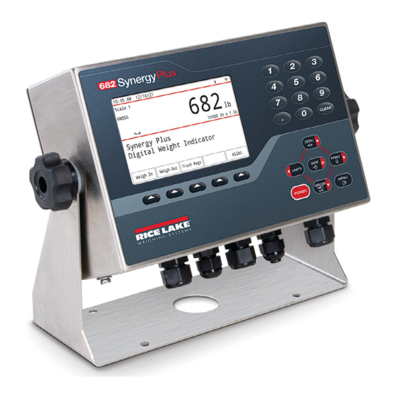
682 Synergy Plus Operation The front panel consists of a full color LCD display with 0.5-in (12.7-mm) tall weight digits. The front panel also includes 24 flat membrane panel, tactile feel buttons, which include six primary scale function buttons, a numeric keypad, five configurable softkeys and a power button. -
Page 27: Status Annunciators
The next parameter in the menu displays. NOTE: Pressing also saves the new value, but the indicator returns up to the current parameter, rather than to the next parameter in the menu. © Rice Lake Weighing Systems ● All Rights Reserved... -
Page 28: Alphanumeric Entry
682 Synergy Plus 3.3.2 Alphanumeric Entry Several parameters in the menu structure require the entry of an alphanumeric value rather than the making of a selection. When these parameters are entered a full keyboard appears on the display. The front panel scale function buttons are used to navigate the keyboard and select alphanumeric options. -
Page 29: General Indicator Operation
The display reads the negative tare value displays. NOTE: Press to zero the scale, if is not displayed. in OIML mode). Display changes to gross weight and Gross is indicated on the display. 2. Press © Rice Lake Weighing Systems ● All Rights Reserved... -
Page 30: Preset Tare (Keyed Tare)
682 Synergy Plus 3.4.7 Preset Tare (Keyed Tare) Tare Function (Section 4.5.1 on page 32) must be set to Keyed Tare or Both for the preset tare feature to function. 1. Remove all weight from the scale and wait for to display. -
Page 31: View Legally Relevant Version
4. Press until displays. Accumulator 5. Press displays. Display Accumulator 6. Press displays. Clear Accumulator 7. Press to clear the accumulator value. displays. 8. Press twice to return to Weigh mode. © Rice Lake Weighing Systems ● All Rights Reserved... -
Page 32: View And Edit Time Value
682 Synergy Plus 3.4.15 View and Edit Time Value To view and edit the current time: 1. Press displays. Audit 2. Press displays. User Menu 3. Press displays. Calibration 4. Press until displays. Time 5. Press to view the current set time. Figure 3-3. -
Page 33: View And Edit Date Value
Weigh mode. NOTE: Date is backed up by the internal battery and is not lost if the main power is interrupted. Section 4.5.5 on page 42 for date formatting options. © Rice Lake Weighing Systems ● All Rights Reserved... -
Page 34: Ethernet, Wi-Fi And Bluetooth® Mac Ids
682 Synergy Plus 3.4.17 Ethernet, Wi-Fi and Bluetooth® MAC IDs The Ethernet MAC ID, Wi-Fi MAC ID and Bluetooth® MAC ID can be viewed through the top-level menu (Section 4.2 on page 30). MAC addresses display in the following format: 88:88:88:88:88:88. -
Page 35: Configure Softkeys
– Prints the selected print transaction Reprint • – Deletes the oldest 4 KB of print transactions Purge Oldest • – Exits the Alibi Storage screen and returns to Weigh mode Cancel © Rice Lake Weighing Systems ● All Rights Reserved... -
Page 36: Enter New Unit Id
682 Synergy Plus 3.4.21 Enter New Unit ID Entering a new Unit ID requires access to Setup mode (Section 4.1 on page 29). 1. Navigate to the Configuration menu within the Setup menu. displays. Configuration 2. Press until displays. Program 3. -
Page 37: Configuration
NOTE: In certain Legal for Trade applications it is necessary to seal the indicator to restrict access to the setup switch (Section 2.7 on page 12). Breaking of the seal terminates the Legal for Trade status of the indicator. © Rice Lake Weighing Systems ● All Rights Reserved... -
Page 38: Main Menu
682 Synergy Plus Main Menu This section provides a flow chart and descriptions for the 682 top-level Main menu. Figure 4-2. Main Menu Audit User Setup Tare MAC ID Fieldbus Version Version Audit Table 4-1. Main Menu Descriptions Menu Description Audit Displays the legally relevant firmware version and allows access to view/print audit trail information;... -
Page 39: User Menu
Table 4-4. Accumulator Menu Parameters Parameter Description Display Accumulator Displays the accumulator value (read only) Print Accumulator Prints the accumulator value to specified port, if setup Clear Accumulator Clears the accumulator value © Rice Lake Weighing Systems ● All Rights Reserved... -
Page 40: Setup Menu
682 Synergy Plus Setup Menu This section provides a flow chart and descriptions for the Setup menu. The Setup menu and can be password protected. See Section 3.4.22 on page 28 for the procedure to set a Setup menu password. Figure 4-6. - Page 41 (Section 2.4.5 on page 8); this parameter must be set correctly to match the actual load cell cable connection to ensure the load cell functions properly with the indicator; Settings: 4-WIRE (default), 6-WIRE © Rice Lake Weighing Systems ● All Rights Reserved...
-
Page 42: Scale Format Menu
682 Synergy Plus 4.5.2 Scale Format Menu This section provides a flow chart and descriptions for the Scale Format menu. Figure 4-8. Scale Format Menu User Setup Tare Configuration Scale Format Calibration Custom Unit 3 Primary Secondary Tertiary Custom Unit 1 Custom Unit 2 Custom Unit 3 Table 4-7. -
Page 43: Calibration Menu
Temporarily zeros the displayed weight of a non-empty scale, after a span calibration was performed; Temp Zero The difference between the temporary zero and the previously calibrated zero value is used as an offset (Section 6.2.2 on page © Rice Lake Weighing Systems ● All Rights Reserved... -
Page 44: Communications Menu
682 Synergy Plus 4.5.4 Communications Menu This section provides a flow chart and descriptions for the Communications menu. Figure 4-10. Communications Menu User Setup Tare Calibration Communications Program Fieldbus Serial Ethernet WiFi & Bluetooth Fieldbus Table 4-9. Communications Menu Descriptions Menu Description Serial... - Page 45 Address – Specifies address used to connect to the port (RS-485 only); Must be set to 0 for RS-422; Enter value: 0–255, 0 (default) Duplex – Specifies FULL (4-wire) or HALF (2-wire) duplex used to connect to the port (RS-485 only); Settings: FULL (default), HALF © Rice Lake Weighing Systems ● All Rights Reserved...
- Page 46 682 Synergy Plus 4.5.4.2 USB Menu This section provides a flow chart and descriptions for the USB menu. Figure 4-12. USB Menu User Setup Tare Calibration Communications Program Serial Ethernet Response Trigger Line Terminator End of Line Delay Echo Response Table 4-11.
- Page 47 Disconnect Time – Sets the disconnect timeout (in seconds); Enter value: 0–60, 0 (default) Http Server Enables the remote HTTP web server (Section 8.0 on page 62); Settings: Off (default), On © Rice Lake Weighing Systems ● All Rights Reserved...
- Page 48 682 Synergy Plus 4.5.4.4 WiFi & Bluetooth Menu This section provides a flow chart and descriptions for the Wi-Fi and Bluetooth® menu. Figure 4-14. WiFi & Bluetooth Menu User Setup Tare Calibration Communications Program WiFi & Bluetooth Fieldbus Response Enabled Trigger Line Terminator End of Line Delay...
- Page 49 Parameters Node Address – Enter value: 1-64, 1 (default) Node Rate – Settings: 125 KB, 250 KB, 500 KB (default) EtherCAT Sub-Parameters: Parameters None – No sub-parameters are needed for EtherCAT © Rice Lake Weighing Systems ● All Rights Reserved...
-
Page 50: Program Menu
682 Synergy Plus 4.5.5 Program Menu This section provides a flow chart and descriptions for the Program menu. Figure 4-16. Program Menu User Setup Tare Communications Program Print Format Displays if Regulatory Mode is set to Industrial Remote Print Industrial Power Up Mode Language Regulatory Mode... - Page 51 Persistent Tare Tare persists through a power cycle; Settings: Off (default), On Remote Print Specifies if the 682 (Local) or another indicator (Remote) handles the print key; Settings: Remote (default), Local Destination © Rice Lake Weighing Systems ● All Rights Reserved...
- Page 52 682 Synergy Plus 4.5.5.1 Industrial Settings Menu This section provides a flow chart and descriptions for the Industrial Settings menu. The Industrial Settings menu only displays if the Regulatory Mode parameter is set to Industrial. Figure 4-17. Industrial Settings Menu User Setup Tare...
-
Page 53: Print Format Menu
Destination Port 1-2 – Destination ports; Settings: RS-232 Port 1 (Port 1 default), RS-232 Port 2, RS-485, TCP Client 1, TCP Server, USB, Serial Option Card Port 1, Serial Option Card Port 2, WiFi & Bluetooth, None (Port 2 default) © Rice Lake Weighing Systems ● All Rights Reserved... - Page 54 682 Synergy Plus Table 4-18. Print Format Menu Parameters (Continued) Parameter Description Audit Format Audit destination print ports where the audit parameters are sent when an Audit Dump is done Destination Port 1-2 – Dump audit destination ports; Settings: RS-232 Port 1 (Port 1 default), RS-232 Port 2, RS-485, TCP Client 1, TCP Server, USB, Serial Option Card Port 1, Serial Option Card Port 2, WiFi &...
-
Page 55: Stream Format Menu
Description Format Specifies the stream format used for streaming output of scale data or specifies the expected input for a serial scale; Settings: RLWS (default) – Rice Lake Weighing Systems stream format (Section 16.5.1 on page 110) Cardinal – Cardinal stream format (Section 16.5.2 on page... -
Page 56: Setpoint Menu
682 Synergy Plus 4.5.8 Setpoint Menu The following sections provide flow charts and descriptions for the Setpoint menu. Figure 4-21. Setpoint Menu User Setup Tare Stream Format Setpoint Digital I/O Setpoint Batching Batching Configuration Setpoint 8 Setpoint 1 Setpoint 2-8 Kind Kind Kind... - Page 57 Push Tare Slot If Kind = Accumulate If Batch = On, and If Kind = or Time Of Day Kind = Accumulate Accumulate Digital Output Sense Batch Branch Enable Access Alias © Rice Lake Weighing Systems ● All Rights Reserved...
- Page 58 682 Synergy Plus 4.5.8.3 If Kind = Pause, Counter, Center of Zero, In Motion, In Range, Batch in Process, Timer, Concurrent Figure 4-24. Setpoints Parameter Group C User Setup Tare Stream Format Setpoint Digital I/O Setpoint Batching Batching Configuration Setpoint 8 Setpoint 1 Setpoint 2-8 If Kind = Counter,...
- Page 59 HIDE – Values cannot be displayed or changed OFF – Values can be displayed but not changed Alias Name for the setpoint; Enter characters: Alphanumeric entry up to 8 characters, SETPT# (default) © Rice Lake Weighing Systems ● All Rights Reserved...
-
Page 60: Digital I/O Menu
682 Synergy Plus 4.5.9 Digital I/O Menu This section provides a flow chart and descriptions for the Digital I/O menu. Figure 4-25. Digital I/O Menu User Setup Tare Setpoint Digital I/O Analog Output Slot 0 Slot 0 Slot 0 Table 4-22. Digital I/O Menu Parameters Parameter Description Bit 1-4... -
Page 61: Softkey Menu
MAC ID Clear Tare Display Tare Clear Tare Table 4-25. Tare Menu Parameters Parameter Description Display Tare Displays the current tare value (read only) Clear Tare Clears the current tare value © Rice Lake Weighing Systems ● All Rights Reserved... -
Page 62: Split Mode Configuration
682 Synergy Plus Split Mode Configuration The 682 supports multi-range and multi-interval scales of either two or three ranges or intervals. The full scale capacity is the second range/interval when just Range 1 is set or the third range/interval when Range 1 and Range 2 are set. Figure 5-1. -
Page 63: Configure A Multi-Range Or Multi-Interval Scale
NOTE: When using Multi-Range, the last range/count by reached is held until returning to zero, even when descending through other ranges. When using Multi-Interval, range/count by changes both when ascending and descending. © Rice Lake Weighing Systems ● All Rights Reserved... -
Page 64: Calibration
682 Synergy Plus Calibration The 682 can be calibrated using the front panel and EDP commands. The following sections describe the procedures required for these calibration methods. NOTE: The 682 requires a Zero Calibration and Span Calibration to be calibrated. The Linear Calibration points are optional; they must fall between zero and span, but must not duplicate zero or span. -
Page 65: Linear Calibration
Once a span calibration is complete, remove the hooks or chains and the test weights from the scale. With all the weight removed, a rezero calibration is used to adjust the zero and span calibration values. © Rice Lake Weighing Systems ● All Rights Reserved... -
Page 66: Edp Command Calibration
682 Synergy Plus EDP Command Calibration Use the following instructions to calibrate the 682 using EDP commands. For information on the EDP commands of the 682, Section 12.0 on page 84. Access to Setup mode (Section 4.1 on page 29) is required. NOTE: The indicator must respond with OK after each step or the calibration procedure must be done again. -
Page 67: Truck Modes
(Section 4.1 on page 29). 1. Navigate to the Configuration menu within the Setup menu. displays. Configuration 2. Press until displays. Program 3. Press displays. Power Up Mode 4. Press until displays. Truck Program © Rice Lake Weighing Systems ● All Rights Reserved... -
Page 68: Using The Truck Register Display
682 Synergy Plus 5. Press displays. Mode 6. Press . The current truck mode setting is highlighted. 7. Press to navigate to the desired truck mode, if necessary. 8. Press to accept the highlighted truck mode. 9. Press twice to navigate back up to the Setup menu level. displays. -
Page 69: Weigh-In Procedure
To use this function, press the Weigh In or Weigh Out softkey, then enter a truck ID containing a decimal point. Truck IDs entered with a decimal point as part of the truck ID are erased from the truck register when the transaction is complete. © Rice Lake Weighing Systems ● All Rights Reserved... -
Page 70: Http Web Server
682 Synergy Plus HTTP Web Server The 682 web server allows for remote viewing of the current 682 Weigh mode values through a web browser. The web server also allows for the use of certain 682 function keys and the ability to view and update active setpoint values. Access Procedure Configuring the HTTP Web Server requires access to Setup mode (Section 4.1 on page... -
Page 71: Browser Display
Ability to view and update setpoint values if Access is set to On for the selected setpoint, otherwise selecting the Change button has no effect NOTE: Text that appears in the message display area of the 682 is not shown via the web server. © Rice Lake Weighing Systems ● All Rights Reserved... -
Page 72: Wi-Fi & Bluetooth® Communications
682 Synergy Plus Wi-Fi & Bluetooth® Communications The 682 is a Wi-Fi and/or Bluetooth® device. The following sections provide details on Wi-Fi and Bluetooth® communications and describe the procedures required to configure these features. The 682 features a Lantronix xPico 200 Series wireless module. Visit to view the xPico 200 Series User www.lantronix.com ®... - Page 73 IMPORTANT: It is recommended to change default passwords to limit access and for security. 6. Press Sign in. The Web Manager loads in the browser and the Status page appears. 7. Click QuickConnect at the top of the left navigation panel. © Rice Lake Weighing Systems ● All Rights Reserved...
- Page 74 682 Synergy Plus 8. A list of wireless networks appear. Click the network name intended to connect the wireless module’s Wi-Fi network to. NOTE: If the necessary network does not display, click the Scan button again. It may take a few tries to show the network. If the network is hidden, enter the network name in the box provided.
- Page 75 Soft AP and use the Web Manager to learn the new IP Address. For more information on features of this card, visit www.lantronix.com to view the xPico 200 Series User Guide. © Rice Lake Weighing Systems ● All Rights Reserved...
-
Page 76: Server Configuration
682 Synergy Plus 9.2.2 Server Configuration The wireless module is configured to be a server by default, with the ability to accept the connection of a client to it. • A Server is waiting to Accept a connection from a Client. •... -
Page 77: Client Configuration
NOTE: The Web Manager provides notes and information related to the current page in the far right column. Descriptions for options and settings are also provided when hovering over the item in question. © Rice Lake Weighing Systems ● All Rights Reserved... -
Page 78: Timeout Configuration
682 Synergy Plus 5. Set the Address and Port as needed to connect to the intended available server connection. 6. Click Submit at the bottom of the page to apply and save the settings. A message displays at the top of the page to confirm the changes have been saved permanently. -
Page 79: Wireless Module Specifications
• Lantronix ConsoleFlow™ Cloud Software Platform, REST, MQTT • Lantronix Discovery Protocol (77FE) • Serial Port, Internal Web Server (HTTP/HTTPS) • XML Configuration and XML Status (CLI, API) • Secure Firmware Upgrade via HTTPS, ConsoleFlow™ © Rice Lake Weighing Systems ● All Rights Reserved... - Page 80 682 Synergy Plus Wireless Module Specifications Continued Protocol Support • DHCP Client, Server (Soft AP), HTTP Server/Client • IPv4, TCP/IP, UDP/IP, ARP, ICMP, Auto-IP, DNS • SNMP v1/v2 • IPv6 Wireless Features • Concurrent Soft AP + STA (Client), Client, Soft AP •...
-
Page 81: Fieldbus Options Configuration
3. Connect the other end of the cable to one of the RS-485 RJ45 ports on the SCT-2200 Fieldbus module. Figure 10-1. SCT-2200 Fieldbus Module Wiring RJ45 Ports Not Used Not Used © Rice Lake Weighing Systems ● All Rights Reserved... -
Page 82: Fieldbus Configuration
682 Synergy Plus 10.2 682 Fieldbus Configuration The following procedure details how to configure the 682 for Fieldbus. Once the necessary 682 parameters are configured and installation complete, communication with the SCT-2200 Fieldbus option (firmware version 1.25 or higher) is ready. 1. -
Page 83: Ethernet/Ip Configuration
• Setup → Communications → Serial → RS-485 or Serial Option Card Port set to Fieldbus • Setup → Communications → Fieldbus → Network Protocol set to PROFINET Download GSDML files from the Rice Lake Weighing Systems website and configure PROFINET based on Figure 10-2. -
Page 84: Data From The Plc To The Indicator
682 Synergy Plus 10.5 Data From the PLC to the Indicator Table 10-3. PLC to Indicator Data Register No. Data Registers Byte Order Byte No Command Register Parameter 1 Parameter 2 Parameter 3 Capacity Units Format Calibration Point Calibration Weight www.RiceLake.com Visit our website... -
Page 85: Commands
Abort Calibration Aborts a calibration and clears any errors Keyboard Enable/Disable Disable keys (parameter 1 = 0) Enable keys (parameter 1 = 1) Read Accumulator Multivalue 1 = returned accumulator value © Rice Lake Weighing Systems ● All Rights Reserved... -
Page 86: Data From The Indicator To The Plc
682 Synergy Plus 10.6 Data From the Indicator to the PLC NOTE: For EtherNet/IP options ONLY, if a generic module is setup, Header information occupies the first four bytes of data and pushes other data registers down. Table 10-5. Indicator to PLC Data Register No. -
Page 87: Onboard Digital I/O Status
Calibration not allowed for MRMI or serial scale Calibration weight out of range Accumulator is not enabled Audit trail is not enabled; Check the jumper to see that it is in the correct position © Rice Lake Weighing Systems ● All Rights Reserved... - Page 88 682 Synergy Plus Unit Values Table 10-10. Values and Units Value Unit None Decimal Point Values Table 10-11. Decimal Point Values Value Decimal Point Use configured decimal point 88.88881 88.88882 88.88885 888.8881 888.8882 888.8885 8888.881 8888.882 8888.885 88888.81 88888.82 88888.85 888888.1 888888.2 888888.5...
-
Page 89: Scale Status
General configuration checksum error Load cell data checksum error Backup battery voltage low Battery backed memory corrupt Load cell A/D error Tare data checksum error Accumulator overflow error Unable to write to non-volatile memory © Rice Lake Weighing Systems ● All Rights Reserved... -
Page 90: Standard Calibration Process
682 Synergy Plus 10.7 Standard Calibration Process Refer to Table 10-3 on page 76 for parameter data information and Table 10-4 on page 77 for descriptions of calibration commands. See Section 10.6.2 on page 79 Section 10.6.3 on page 79 for possible command responses during the calibration process. -
Page 91: Revolution
Revolution is used to update the firmware of the 682 indicator. The link to begin this process is available on the Revolution home screen. Updating the firmware defaults the configuration settings. © Rice Lake Weighing Systems ● All Rights Reserved... -
Page 92: Edp Commands
682 Synergy Plus 12.0 EDP Commands The 682 indicator can be controlled by a personal computer connected to one of the indicator communication ports. Control is provided by a set of commands which can simulate front panel key press functions, return and change setup parameters, and perform reporting functions. -
Page 93: Reporting Commands
Table 12-4. Reset Configuration Command Command Function RESETCONFIGURATION Restores all configuration parameters to default values (Setup mode only) NOTE: All scale calibration settings are lost when the RESETCONFIGURATION command is run © Rice Lake Weighing Systems ● All Rights Reserved... -
Page 94: Scale Parameter Setting Commands
682 Synergy Plus 12.5 Scale Parameter Setting Commands Parameter setting commands allow the current value for a configuration parameter to be displayed or changed. Current configuration parameter settings can be displayed in Setup mode or Weigh mode using the following syntax: command<ENTER>... - Page 95 0.0–100.0, 0.0 (default) SC.RTZGRAD#n Number of graduations from the zero base at which the 0.0–100.0, 0.4 (default) accumulator re-arms itself For commands ending with #n, n is the scale number (1) © Rice Lake Weighing Systems ● All Rights Reserved...
-
Page 96: Serial Port Setting Commands
682 Synergy Plus 12.6 Serial Port Setting Commands The following commands can be used to configure serial port parameters. Table 12-6. Serial Port Commands Command Description Values EDP.TRIGGER#p Port serial input trigger function CMD (default), STRIND, STRLFT, REMOTE 1200, 2400, 4800, 9600 (default), 19200, 28800, 38400, 57600, 115200 EDP.BAUD#p Port baud rate EDP.BITS#p... -
Page 97: Wi-Fi And Bluetooth® Setting Commands
PROFINET gateway; disabled if Auto IP is ON 0.0.0.0 (default) FIELDBUS.PROFINET.IPADDR PROFINET IP address; disabled if Auto IP is ON 0.0.0.0 (default) 255.255.255.0 (default) FIELDBUS.PROFINET.SUBNET PROFINET subnet; disabled if Auto IP is ON © Rice Lake Weighing Systems ● All Rights Reserved... -
Page 98: Alibi Setting Commands
682 Synergy Plus 12.10 Alibi Setting Commands The following command can be used to configure Alibi parameters. Table 12-10. Alibi Commands Command Description Values ALIBI.ENABLED Enables the storage of print transactions in the Alibi database OFF (default), ON ALIBI.COUNT Returns number of records present –... -
Page 99: Feature Commands
NO (default), YES REG.KTARE Always allow keyed tare NO, YES (default) REG.MTARE Multiple tare action REPLACE (default), REMOVE, NOTHING NO (default), YES REG.NTARE Allow negative tare NTEP defaults shown for regulatory command values © Rice Lake Weighing Systems ● All Rights Reserved... -
Page 100: Setpoint Commands
682 Synergy Plus Table 12-14. Regulatory Commands (Continued) Command Description Values REG.CTARE Allow Clear key to clear tare/accumulator NO, YES (default) REG.NEGTOTAL Allow total scale to display negative value NO (default), YES REG.PRTMOT Allow print while in motion NO (default), YES NO, YES (default) REG.PRINTPT Add PT to keyed tare print... -
Page 101: Batching Control Commands
AUX.PORT#1-4 AUX.PORT2#1-4 TRFMT Truck print format string TRFMT.PORT TRFMT.PORT2 TRWINFMT Truck weigh-in print format string TRWINFMT.PORT TRWINFMT.PORT2 TRWOUTFMT Truck weigh-out print format string TRWOUTFMT.PORT TRWOUTFMT.PORT2 AUD.DEST1 Audit destination print ports AUD.DEST2 © Rice Lake Weighing Systems ● All Rights Reserved... -
Page 102: Digital I/O Commands
682 Synergy Plus 12.18 Digital I/O Commands The following commands can be used to configure digital I/O parameters. Table 12-18. Digital I/O Commands Command Description Values DIO.b#s Sets DIO type OFF (default), OUTPUT, PRIM, PRINT, SEC, TARE, UNITS, ZERO, BATRUN, BATSTART, BATPAUSE, BATRESET, BATSTOP, CLEAR, CLRACC, CLRCN, CLRTAR, DSPACC, DSPTAR, GROSS, KBDLOC, NET, NT/GRS Valid bit values (b) are 1-4;... -
Page 103: Weigh Mode Commands
Returns the tare weight in tertiary units For commands ending with #n, n is the scale number (1); For commands ending with #p, p is the port number (1-6), see Section 12.6.1 on page 88 © Rice Lake Weighing Systems ● All Rights Reserved... -
Page 104: Print Formatting
682 Synergy Plus 13.0 Print Formatting The 682 provides multiple print formats, Gross, Net, Accumulator, Setpoint, Header, Auxiliary 1-4, Truck, Truck Weigh-In, and Truck Weigh-Out, which determine the format of the printed output when the key is pressed. If a tare has been entered or Print acquired, Net is used;... - Page 105 Tare weight (inbound) for current ticket in displayed units <TR3> Net weight (outbound) for current ticket in displayed units NOTE: TR1, TR2 and TR3 truck ticket weight data includes keywords INBOUND, KEYED and RECALLED, as needed. © Rice Lake Weighing Systems ● All Rights Reserved...
-
Page 106: Customizing Print Formats
682 Synergy Plus Table 13-1. Print Format Tokens (Continued) Token Description Supported Ticket Formats Alert Format Tokens <ERR> Alert error message (system-generated) ALERT Table 13-2. Default Print Formats Format Default Format String When Used GFMT GROSS<G><NL2><TD><NL> Weigh mode – no tare in system NFMT GROSS<G><NL>TARE<SP><T><NL>NET<SP2><N>... -
Page 107: Setpoints
Performs functions based on a specified value above a referenced setpoint, using the same weight mode as the referenced setpoint Negative Relative Performs functions based on a specified value below a referenced setpoint, using the same weight mode as the referenced setpoint © Rice Lake Weighing Systems ● All Rights Reserved... - Page 108 682 Synergy Plus Table 14-1. Setpoint Kinds (Continued) Parameter Description Batch Continuous Percent Relative Performs functions based on a specified percentage of the target value of a referenced setpoint, using the same weight mode as the referenced setpoint; the actual target value of the Percent Relative setpoint is calculated as a percentage of the target value of the referenced setpoint Pause Pauses the batch sequence indefinitely;...
-
Page 109: Batch Operations
Figure 14-2 on page 102. Each switch uses a separate digital input. Digital I/O Bit 1 must be set to Batch Start and Bit 2 must be set to Batch Run. © Rice Lake Weighing Systems ● All Rights Reserved... - Page 110 682 Synergy Plus Once cables and switches have been connected to the indicator, use the setup switch to place the indicator in Setup mode. Use the Digital I/O menu (Section 4.5.9 on page 52) to configure digital input and output functions. Figure 14-2.
-
Page 111: Batching Examples
Timer. If the Timer expires before Setpoint 5 starts, Digital Output 4 is turned on as an alarm to signal a process fault. Setpoint 6 Start = 4 Kind = Timer End = 5 Value = 100 Digital Output = 4 © Rice Lake Weighing Systems ● All Rights Reserved... -
Page 112: Example 2
682 Synergy Plus 14.3.2 Example 2 The following example uses six setpoints to control a two-speed fill operation where both fast and slow feeds are on simultaneously. Bits 1 and 2 in the Digital I/O menu (Section 4.5.9 on page 52) are assigned to Batch Start and Batch Run functions. -
Page 113: Maintenance
The maintenance information in this manual is designed to cover aspects of maintaining and troubleshooting the 682 indicator. Contact the local Rice Lake Weighing Systems dealer if a problem requires technical assistance. NOTE: Have the scale model number and serial number available when calling for assistance. -
Page 114: Battery Replacement
IMPORTANT: Use anti-static protection for grounding and to protect components from electrostatic discharge (ESD) when working inside the 682 enclosure. Procedures requiring work inside the 682 must be performed by qualified service personnel only. Figure 15-1. Non-Conductive Screw Driver Placement PN/Rev RICE LAKE ASSY CR2032 CR2032 LED3... -
Page 115: Board Replacement
IMPORTANT: Always verify indicator has been returned back to a safe state with the proper installation of all connections and a complete functions test before reinstalling the backplate and returning the indicator back into service. © Rice Lake Weighing Systems ● All Rights Reserved... -
Page 116: Appendix
682 Synergy Plus 16.0 Appendix 16.1 Error Messages The 682 indicator provides a number of error messages. When an error occurs, the message displays on the indicator. 16.1.1 Displayed Error Messages The 682 provides a number of front panel error messages to assist in problem diagnosis. Table 16-1 lists these messages and their meanings. -
Page 117: Audit Trail Support
(1). Table 16-2. Status Codes Returned on the ZZ Command Decimal Value Annunciator lb/primary units kg/secondary units Tare entered Keyed tare entered Gross Center of zero Standstill © Rice Lake Weighing Systems ● All Rights Reserved... -
Page 118: Continuous Data (Stream) Output Formats
• Avery Weigh-Tronix (Section 16.5.3 on page 111) • Mettler Toledo (Section 16.5.4 on page 111) 16.5.1 Rice Lake Weighing Systems Stream Format (RLWS) Figure 16-1. Rice Lake Weighing Systems Stream Data Format <STX> <POL> <wwwwwww> <UNIT> <G/N> <S> <TERM>... -
Page 119: Avery Weigh-Tronix Stream Format (Wtronix)
0 = Positive indicated weight value setup. 1 = Negative indicated weight value 0 = In range 1 = Out of range 0 = lb 0 = Stable 1 = kg 1 = Motion © Rice Lake Weighing Systems ● All Rights Reserved... -
Page 120: Stream Format Tokens
682 Synergy Plus 16.6 Stream Format Tokens Table 16-3. Stream Format Tokens Format Identifier Defined By Description <P[G | N | T]> STRM.POS#n Polarity – Specifies positive or negative polarity for the current or specified STRM.NEG#n (Gross/Net/Tare) weight on the source scale; Possible values are SPACE, NONE, + (for STR.POS#n) or –... -
Page 121: Digital Filtering
This can be 6.25, 7.5, 12.5, 15, 25, 30, 50, 60 or 120 hertz (readings per second). Set the A/D sample rate to the lowest setting required for the application. Lower settings result in better stability. © Rice Lake Weighing Systems ● All Rights Reserved... -
Page 122: Digital Rolling Average Filter (Average Only)
682 Synergy Plus 16.7.1 Digital Rolling Average Filter (Average Only) The digital rolling average filter uses mathematical averaging with three stages. These configurable stages control the effect of a single A/D reading on the displayed weight. When an A/D reading outside of a predetermined band is encountered, the digital rolling average filter is overridden and the display jumps directly to the new value. -
Page 123: Adaptive Filter (Adaptive Only)
Figure 16-5. 500 lb Displayed Weight Progression With No Damping With Damping When Weight is Placed on Scale When Full Weight and Full Weight Value Displays Value Displays When Weight is Placed on Scale DAMPVAL © Rice Lake Weighing Systems ● All Rights Reserved... -
Page 124: Regulatory Mode Functions
682 Synergy Plus 16.8 Regulatory Mode Functions Table 16-4. Tare and Zero Key Functions for Regulatory Mode Parameter Settings Regulatory Weight On Tare In Front Panel Front Panel Parameter Scale System Key Tare Key Zero NTEP Zero “0000000” Zero Clear tare Zero Negative No action... -
Page 125: Ascii Character Chart
Ctrl-E Ctrl-F & Ctrl-G ’ Ctrl-H Ctrl-I Ctrl-J Ctrl-K Ctrl-L Ctrl-M Ctrl-N Ctrl-O Ctrl-P Ctrl-Q Ctrl-R Ctrl-S Ctrl-T Ctrl-U Ctrl-V Ctrl-W Ctrl-X Ctrl-Y Ctrl-Z Ctrl-[ Ctrl-\ < Ctrl-] Ctrl-^ > Ctrl-_ © Rice Lake Weighing Systems ● All Rights Reserved... -
Page 126: Compliance
EN 61326-1:2013, EN 61000-3-3:2013, EN 61000-6-2, EN 61000-6-4, EN55011:2009/A1:2010 2014/53/EU RED EN 301 489-17 V3.2.4, EN 300 328 V2.2.2, EN 301 893 V2.1.1 2011/65/EU RoHS EN 50581:2012 Rice Lake, WI USA Brandi Harder March 30, 2022 Quality Manager www.RiceLake.com Visit our website... - Page 127 EN 61326-1:2013, EN 61000-3-3:2013, EN 61000-6-2, EN 61000-6-4, EN55011:2009/A1:2010 2017/1206 Radio EN 301 489-17 V3.2.4, EN 300 328 V2.2.2, EN 301 893 V2.1.1 2012/3032 RoHS EN 50581:2012 Rice Lake, WI USA Brandi Harder March 30, 2022 Quality manager © Rice Lake Weighing Systems ● All Rights Reserved...
-
Page 128: Specifications
682 Synergy Plus 18.0 Specifications Power Temperature Range AC line voltage: 100–240 VAC Legal: 14° F to 104° F (-10° C to 40° C) Frequency: 50–60 Hz Industrial: 14° F to 122° F (-10° C to 50° C) DC line voltage: 9–36 VDC Rating / Material Power Consumption... - Page 130 © Rice Lake Weighing Systems Specifications subject to change without notice. 230 W. Coleman St. • Rice Lake, WI 54868 • USA U.S. 800-472-6703 • Canada/Mexico 800-321-6703 • International 715-234-9171 • Europe +31 (0)26 472 1319 April 8, 2022 PN 204533 Rev A...
Need help?
Do you have a question about the REVOLUTION 682 Synergy Plus and is the answer not in the manual?
Questions and answers