Table of Contents
Advertisement
Advertisement
Table of Contents

Subscribe to Our Youtube Channel
Related Manuals for Rice Lake IQ plus 355


Summary of Contents for Rice Lake IQ plus 355
-
Page 1: Installation Manual
IQ plus ® Digital Weight Indicator Version 1.17 Installation Manual 66503... -
Page 3: Table Of Contents
Key Press Commands............. 27 © 2006 Rice Lake Weighing Systems. All rights reserved. - Page 4 7.11 Specifications..............46 IQ plus 355 Limited Warranty ........................ 47...
-
Page 5: About This Manual
Two configurable digital inputs legal seal is affixed to the back of the indicator, • Electronic data processing (EDP) port for full this is the only mode in which the IQ plus 355 can duplex, RS-232 communications at up to operate. 9600 bps Setup mode •... -
Page 6: Front Panel Keypad
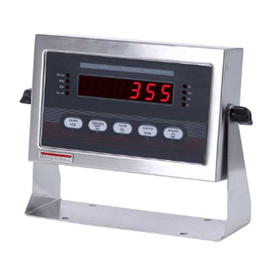
Figure 1-1. IQ plus 355 Front Panel, Showing LED Annunciators and Normal Mode Key Functions LED Annunciators The IQ plus 355 display uses a set of eight LED annunciators to provide additional information about the value being displayed: •... -
Page 7: Indicator Operations
/ kg lb / lb Table 1-1. Units Annunciators, Showing Primary / Secondary LEDs Used for All Configurations Indicator Operations Basic IQ plus 355 operations are summarized below. 1.4.4 Acquire Tare 1. Place container on scale and wait for the 1.4.1... -
Page 8: Installation
If any parts were damaged in shipment, The IQ plus 355 provides four cord grips for cabling notify Rice Lake Weighing Systems and the shipper into the indicator: one for the power cord, three to immediately. -
Page 9: Cable Grounding
Tr a n s f o r m e r +EXC –SENSE +SENSE A / D C o n v e r t e r JMP3 –SIG ANALOG +SIG LOAD –5V TEST CELL COMP Keypad Connector Figure 2-3. IQ plus 355 CPU and Power Supply Board Installation... -
Page 10: Load Cells
–EXC measurements, set the Figure 2-6 on page 10. jumper in the OFF position. NOTE: Early versions of the IQ plus 355 CPU board used 2.3.3 Serial Communications and Digital Inputs a 7-pin load cell connector. The 7-pin connector is not To attach serial communications and digital input compatible with the current 6-pin header. -
Page 11: Analog Output
2.3.4 Analog Output If the optional analog output module is installed, If you must remove the IQ plus 355 CPU board, use attach the output cable to connector J1 on the analog the following procedure: output board. Table 2-3 lists the analog output pin 1. -
Page 12: Replacement Parts
Replacement Parts Table 2-4 lists replacement parts for the IQ plus 355, including all parts referenced in Figures 2-5 through 2-9. Number Description (Quantity) Figure 14626 Kep nuts, 8-32NC hex (3) Figure 2-5 on page 9, Figure 2-8 on page 11... - Page 13 Figure 2-5. IQ plus 355 Backplate and Tilt Stand Assemblies Installation...
- Page 14 filter Cable tie Cable tie mounts for setup switch wires Brown wire AC power in from line filter Blue wire Line Filter Connection to JP7 Figure 2-6. IQ plus 355 Enclosure and CPU Board IQ plus 355 Installation Manual...
- Page 15 To backplate 1/3X ground post To line filter To power cord Figure 2-7. Line Filter Assembly Figure 2-8. Ground Post Assembly Figure 2-9. IQ plus 355 Enclosure and Overlay Installation...
-
Page 16: Configuration
Configuration Methods mode. The IQ plus 355 indicator can be configured by using 4. Start the Revolution program. the front panel keys to navigate through a series of Figure 3-1 shows an example of one of the Revolution configuration menus or by sending commands or configuration displays. -
Page 17: Front Panel Configuration
Front Panel Configuration The IQ plus 355 indicator can be configured using a series of menus accessed through the indicator front panel when the indicator is in setup mode. Table 3-1 summarizes the functions of each of the main menus. -
Page 18: Menu Structures And Parameter Descriptions
(see Figure 3-4). Menu Structures and Parameter Descriptions The following sections provide graphic representations of the IQ plus 355 menu structures. In the actual menu structure, the settings you choose under each parameter are arranged horizontally. To save page space, menu choices are shown in vertical columns. -
Page 19: Configuration Menu
3.2.1 Configuration Menu Figure 3-5. Configuration Menu CONFIG Menu Parameter Choices Description Level 2 submenus GRADS 10000 Graduations. Specifies the number of full scale graduations. The value entered must be in number the range 1–100 000 and should be consistent with legal requirements and environmental limits on system resolution. - Page 20 Tare function. Enables or disables push-button and keyed tares. Possible values are: NOTARE BOTH: Both push-button and keyed tares are enabled PBTARE NOTARE: No tare allowed (gross mode only) KEYED PBTARE: Push-button tares enabled KEYED: Keyed tare enabled Table 3-2. Configuration Menu Parameters (Continued) IQ plus 355 Installation Manual...
-
Page 21: Format Menu
3.2.2 Format Menu Figure 3-6. Format Menu FORMAT Menu Parameter Choices Description Level 2 submenus PRIMAR DECPNT Specifies the decimal position, display divisions, and units used for the primary units. See DSPDIV Level 3 submenu parameter descriptions. UNITS SECNDR DECPNT Specifies the decimal position, display divisions, units, and conversion multiplier used for DSPDIV the secondary units. - Page 22 See Section 7.6 on page 41 for a list of multipliers. To toggle between primary and secondary units, press the UNITS key. MULEXP decimal Multiplier exponent. Sets the decimal position for multiplier values. position Table 3-3. Format Menu Parameters (Continued) IQ plus 355 Installation Manual...
-
Page 23: Calibration Menu
Use this parameter only after WZERO and WSPAN have been set. See Section 4.1 on page 24 for more information about using this parameter. Table 3-4. Calibration Menu Parameters 3.2.4 Serial Menu See Section 7.3 on page 37 for information about the IQ plus 355 serial data format. Figure 3-8. Serial Menu Configuration... -
Page 24: Program Menu
STREAM Selects the serial port used for continuous transmission. See Section 7.3 on page 37 for information about the IQ plus 355 continuous data format. PRNDES Print destination. Selects the port for data transmission when the PRINT key is pressed or the KPRINT EDP command is sent. -
Page 25: Print Format Menu
PROGRM Menu Parameter Choices Description Level 2 submenus PWRUPM Power up mode. In GO mode, the indicator goes into operation immediately after a brief power DELAY up display test. In DELAY mode, the indicator performs a power up display test, then enters a 30-second warm up period. -
Page 26: Digital Input Menu
• KBDLOC disables the keypad while the digital input is held low. CLRCN • HOLD holds the current display. Releasing this input clears the running average filter. KBDLOC HOLD Table 3-7. Digital Input Menu Parameters IQ plus 355 Installation Manual... -
Page 27: Analog Output Menu
3.2.8 Analog Output Menu The ALGOUT menu is used only if the analog output option is installed. If the analog output option is installed, configure all other indicator functions and calibrate the indicator (see Section 4.0 on page 24) before configuring the analog output. -
Page 28: Calibration
Calibration The IQ plus 355 can be calibrated using the front panel, EDP commands, or the Revolution ™ configuration utility. Each method consists of the following steps: • Zero calibration • Entering the test weight value • Span calibration •... -
Page 29: Edp Command Calibration
3. Place test weights on the scale and use the EDP Command Calibration WVAL command to enter the test weight To calibrate the indicator using EDP commands, the value in the following format: indicator EDP port must be connected to a terminal or WVAL=nnnnnn<CR>... -
Page 30: More About Calibration
126 000 147 000 168 000 189 000 210 000 231 000 252 000 273 000 294 000 315 000 420 000 525 000 735 000 1 050 000 Table 4-1. Ideal A/D Raw Counts IQ plus 355 Installation Manual... -
Page 31: Edp Commands
<N>, and <T>). KPRINT EDP command is received. If a tare has been entered or acquired, NFMT is used; otherwise, GFMT The default IQ plus 355 print formats are shown in is used. Table 6-2: Each print format can be customized to include up to... - Page 32 32400 WEST HIGHWAY ROAD (see the ASCII character chart on page 39) and are SMALLTOWN shown as blanks. The IQ plus 355 can send or receive any ASCII character; the character printed depends on 1345 LB GROSS the particular ASCII character set implemented for the receiving device.
- Page 33 EDP Commands The IQ plus 355 indicator can be controlled by a personal computer or remote keyboard connected to Command Function the indicator EDP port. Control is provided by a set of EDP commands that can simulate front panel key...
-
Page 34: Reporting Commands
DUMPALL List all parameter values the following syntax: VERSION Write IQ plus 355 software version command<ENTER> Most parameter values can be changed in setup mode Write current displayed weight with units only. Use the following command syntax when identifier. - Page 35 Command Description Values PRI.DECPNT Primary units decimal position 8.88888, 88.8888, 888.888, 8888.88, 88888.8, 888888, 888880 PRI.DSPDIV Primary units display divisions 1D, 2D, 5D PRI.UNITS Primary units LB, KG, OZ, TN, T, G, NONE SEC.DECPNT Secondary units decimal position 8.88888, 88.8888, 888.888, 8888.88, 88888.8, 888888, 888880 SEC.DSPDIV Secondary units display divisions 1D, 2D, 5D...
- Page 36 Transmit net weight in non-displayed units Transmit tare weight in non-displayed units Query system error conditions nnnnn nnnnn See Section 7.1.2 on page 36 for detailed information about the XE command response format. Table 5-11. Normal Mode EDP Commands IQ plus 355 Installation Manual...
-
Page 37: Print Formatting
310 Command 355 Command Description KZERO Sets scale to zero. Valid only in Operate Mode. KTARE Performs a front panel tare operation. Entering “FT <EOL>” acquires a tare like pressing the TARE key. Clear Tare Tare out (removes the tare value) KPRIM Selects “lb”... -
Page 38: Saving And Transferring Data
The IQ plus 355 responds by sending include changed serial communications a l l c o n f i g u r a t i o n p a r a m e t e r s t o t h e P C a s settings, edit the data file to place the serial ASCII-formatted text. -
Page 39: Appendix
Error Messages The IQ plus 355 indicator provides a number of error messages. When an error occurs, the message is shown on the indicator LED display. Error conditions can also be checked remotely by using the XE EDP command as described in Section 7.1.2. -
Page 40: Using The Xe Edp Command
7.1.2 Using the XE EDP Command The XE EDP command can be used to remotely query Error the IQ plus 355 for the error conditions shown on the Code Description Binary Value front panel. The XE command returns two 5-digit... -
Page 41: Continuous Output (Stream) Format
Continuous Output (Stream) Format Figure 7-1 shows the continuous output format sent to the IQ plus 355 EDP or printer port when the STREAM parameter (SERIAL menu) is set to either EDP or PRN. CONFIG XXXXXXX FORMAT CALIBR SERIAL PROGRM... -
Page 42: Ascii Character Chart
See Section 7.5 used by the output device. on page 40 for information about the IQ plus 355 LED display. Control ASCII... - Page 43 ASCII ASCII ASCII ASCII α Ç á β ü í Γ é ó π â ú Σ ä ñ σ à Ñ µ å ª τ ç º Φ ê ¿ Θ ë Ω è ¬ δ ï ∞ î φ...
-
Page 44: Front Panel Display Characters
Front Panel Display Characters Figure 7-2 shows the 7-segment LED character set used to display alphanumeric characters on the IQ plus 355 front panel. Figure 7-2. IQ plus 355 Display Characters IQ plus 355 Installation Manual... -
Page 45: Conversion Factors For Secondary Units
Conversion Factors for Secondary Units Primary Unit x Multiplier Secondary Unit The IQ plus 355 has the capability to mathematically grains 0.064799 grams convert a weight into many different types of units and instantly display those results with a press of the 0.002286... -
Page 46: Digital Filtering
Digital Filtering The IQ plus 355 uses averaged digital filtering to reduce the effect of vibration on weight readings. Adjustable threshold and sensitivity functions allow quick settling by suspending filter averaging, allowing the weight reading to jump to the new value. Figure 7-3 shows the digital filter parameters on the CONFIG menu. -
Page 47: Setting The Digital Filter Parameters
7.7.3 Setting the Digital Filter Parameters Fine-tuning the digital filter parameters greatly vibration effects on the scale. (Leave DFTHRH set to NONE.) Reconfigure as improves indicator performance in heavy-vibration necessary to find the lowest effective values environments. Use the following procedure to for the DIGFLx parameters. -
Page 48: Test Mode
• Set analog output state to zero or full scale Figure 7-6. Test Menu GROSS ZERO T ARE UNITS PRINT Units TEST MODE KEY FUNCTIONS Figure 7-7. Front Panel Key Functions in Test Mode IQ plus 355 Installation Manual... -
Page 49: 7.10 Software Revision History
Press and hold Enter key to send ASCII “U” characters (decimal 85) from the serial port. ECHO R Echo received characters Press and hold Enter key to view characters received at serial port. IQ plus 355 display shows lower-case characters as blanks. NOTE: Table 7-7. Test Menu Functions 7.10 Software Revision History For a complete description of recent software revisions, visit our web site at www.rlws.com. -
Page 50: 7.11 Specifications
Optional: fully isolated, voltage or current output,14-bit resolution. Voltage output: 0 –10 VDC OIML Load resistance:1KΩ minimum R76-2 Test Certificate TC6008 Current output: 4–20 mA Approval T5692 External loop resistance: 500Ω Accuracy Class maximum : 3 000 IQ plus 355 Installation Manual... -
Page 51: Iq Plus 355 Limited Warranty
IQ plus 355 Limited Warranty Rice Lake Weighing Systems (RLWS) warrants that all RLWS equipment and systems properly installed by a Distributor or Original Equipment Manufacturer (OEM) will operate per written specifications as confirmed by the Distributor/OEM and accepted by RLWS. All systems and components are warranted against defects in materials and workmanship for two years.
Need help?
Do you have a question about the IQ plus 355 and is the answer not in the manual?
Questions and answers