
Related Manuals for Rice Lake Synergy 680HE


Summary of Contents for Rice Lake Synergy 680HE
- Page 1 680HE Synergy Hostile Environment Digital Weight Indicator Technical Manual June 11, 2020 PN 197709 Rev A...
- Page 2 All information contained within this publication is, to the best of our knowledge, complete and accurate at the time of publication. Rice Lake Weighing Systems reserves the right to make changes to the technology, features, specifications and design of the equipment without notice.
-
Page 3: Table Of Contents
Enter New Unit ID ................19 Technical training seminars are available through Rice Lake Weighing Systems. - Page 4 CPU Ports ................. 47 Rice Lake continually offers web-based video training on a growing selection of product-related topics at no cost.
- Page 5 Rice Lake Weighing Systems Stream Format (RLWS) ........
- Page 6 680HE Synergy Indicator Contents Rice Lake continually offers web-based video training on a growing selection of product-related topics at no cost. Visit www.ricelake.com/webinars www.RiceLake.com Visit our website...
-
Page 7: Introduction
Do not operate or work on this equipment unless this manual has been read and all instructions are understood. Failure to follow the instructions or heed the warnings could result in injury or death. Contact any Rice Lake Weighing Systems dealer for replacement manuals. -
Page 8: Operating Modes
680HE Synergy Indicator Operating Modes Weigh Mode Weigh mode is the default mode of the indicator. The indicator displays gross or net weights as required, using the annunciators to indicate scale status and the type of weight value displayed. User Mode User mode is accessible by pressing on the front panel. -
Page 9: Installation
Figure 2-1. Product Diagram 14.0'' (355.6 mm) 13.3'' (337.8 mm) 12.5'' (317.5 mm) 11.8'' (299.7 mm) 10.5'' (266.7 mm) 6.5'' (165.1 mm) 13.0'' (330.2 mm) 8.0'' (203.2 mm) Table 2-1. Product Dimensions © Rice Lake Weighing Systems ● All Rights Reserved... -
Page 10: Mounting Instructions
680HE Synergy Indicator Mounting Instructions The 680HE can be mounted on a wall or vertical surface using the mounting feet on the sides of the enclosure. 1. Using the mounting feet holes as a template, mark the screw locations. 2. Drill holes for the screws. 3. -
Page 11: Cable Connections
RJ45 Bulkhead (option) 20 in-lb (2.3 N-m) Table 2-3. Component Torque Ratings For reference, it is recommended to tighten the cord grip dome nuts until the rubber insert starts to bulge. Note © Rice Lake Weighing Systems ● All Rights Reserved... -
Page 12: Cable Shield Grounding
680HE Synergy Indicator 2.4.2 Cable Shield Grounding Except for the power cord, all cables routed through the cord grips must be shield grounded. • Use hardware provided in the parts kit to install shielding clamps on the back panel of the enclosure •... -
Page 13: Power Cable
RS-232 Port 2 – – – – – – Table 2-6. J3 Pin Assignments (RS-232) RS-232 Port 1 = RS2321 and RS-232 Port 2 = RS2322 in the 680HE menu structure. Note © Rice Lake Weighing Systems ● All Rights Reserved... -
Page 14: Rs-485/422 Serial Communications
680HE Synergy Indicator 2.4.6 RS-485/422 Serial Communications The J4 connector (Section 2.5 on page 11) is intended to provide a connection point for the RS-485/422 serial communications. Table 2-7 for the pin assignments for the J4 connector. Connector RS-485 422/485 Adapter TDA(-) TDB(+) RDA(-) -
Page 15: Micro Usb Device Communications
The port communicates in the same way regardless of these settings. This port is not a host port and is not intended to be connected to other devices such as keyboards, memory sticks or printers. © Rice Lake Weighing Systems ● All Rights Reserved... -
Page 16: Ethernet
680HE Synergy Indicator 2.4.9 Ethernet The 680HE features Ethernet TCP/IP 10Base-T/100Base-TX communication using the J8 connector (Section 2.5 on page 11), and can support two simultaneous connections, one as a server, the other as a client. Through an Ethernet network, software applications can communicate with the 680HE using the EDP command set (Section 7.0 on page 44), or data can be streamed continuously from the 680HE, or printed on demand. -
Page 17: Option Card Port
Figure 2-7. 680HE CPU Board Connectors • Load Cell (J1) • RS-485/422 (J4) • Micro USB (J7) • Power (J10) • RS-232 1-2 (J3) • Digital I/O (J5) • Ethernet (J8) • Option Slot (J22/J23) © Rice Lake Weighing Systems ● All Rights Reserved... -
Page 18: Sealing The Indicator (Optional)
680HE Synergy Indicator Sealing the Indicator (Optional) Use a lead wire seal to restrict access of the setup and audit jumpers, electronics, electrical contacts and Legal for Trade configuration parameters of the 680HE. The audit jumper (J24) must be set to OFF to restrict access to the configuration parameters. Note Latch Clevis Pin... -
Page 19: Replacement Parts
AC Power Cord Assembly, NEMA 5-15 15631 Cable Tie, 3 inch Nylon 68600 Cord Grip, PG11 – 200034 680HE Indicator Parts Kit 68601 Nut, PG11 Black Nylon Table 2-13. Replacement Parts List © Rice Lake Weighing Systems ● All Rights Reserved... -
Page 20: Operation
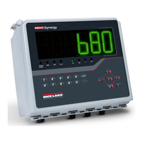
680HE Synergy Indicator Operation The front panel consists of a seven-segment display with six 2.5'' (63.5 mm) tall digits. Front panel also includes 18 flat membrane panel, tactile feel buttons, which include six primary scale function buttons and a numeric keypad. There are eight LED annunciators for units and scale functions. -
Page 21: Led Annunciators
The next parameter in the menu displays. Pressing also saves the new value, but the indicator returns up to the current parameter, rather than to the Note next parameter in the menu. © Rice Lake Weighing Systems ● All Rights Reserved... -
Page 22: Alphanumeric Entry
680HE Synergy Indicator 3.3.2 Alphanumeric Entry Several parameters in the menu structure require the entry of an alphanumeric value rather than the making of a selection. The end of the alphanumeric character string is indicated by the “ ” character symbol. Note Follow this procedure to enter an alphanumeric value: 1. -
Page 23: Acquire Tare
. dsptar displays. 4. Press . clrtar displays. 5. Press to clear the stored tare value. ok displays. 6. Press to return the audit menu. 7. Press to return to weigh mode. © Rice Lake Weighing Systems ● All Rights Reserved... -
Page 24: View Audit Trail Counters
680HE Synergy Indicator 3.4.10 View Audit Trail Counters The audit trail calibration and configuration counters can be viewed in user mode. 1. Press . audit displays. 2. Press . lrv displays. 3. Press . calibr displays. 4. Press . The audit trail calibration counter displays. 5. -
Page 25: Clear Accumulator
Time is backed up by the internal battery and is not lost if the main power is interrupted. Note Section 4.4.5 on page 30 for time formatting options. © Rice Lake Weighing Systems ● All Rights Reserved... -
Page 26: View And Edit Date Value
680HE Synergy Indicator 3.4.17 View and Edit Date Value To view and edit the current date: 1. Press . audit displays. 2. Press multiple times until date displays. 3. Press to view the current set date. 4. To edit the date value use the following method: •... -
Page 27: Configuration
In certain Legal for Trade applications it is necessary to seal the indicator (Section 2.6 on page 12) to restrict access Note to setup mode. Breaking of the seal terminates the Legal for Trade status of the indicator. © Rice Lake Weighing Systems ● All Rights Reserved... -
Page 28: Main Menu
680HE Synergy Indicator Main Menu Audit Setup Setpnt Accum Tare time date mac id Vers Figure 4-2. Main Menu Menu Description Audit – Displays the legally relevant firmware version and allows access to view/print audit trail information; See Section 4.3 Audit Setup –... -
Page 29: Setup Menu
If 0 is selected, ztrkbnd must also be set to 0; Enter value: 0–100, 1 (default) Table 4-4. Setup – Configuration Menu Descriptions © Rice Lake Weighing Systems ● All Rights Reserved... - Page 30 680HE Synergy Indicator Menu Description Overload – Determines the point at which the display blanks and the overload error message displays (^^^^^^); Ovrloa Maximum legal value varies depending on local regulations; Settings: FS+2% (default), FS+1D, FS+9D, FS Sample Rate – Selects measurement rate, in samples per second, of the analog-to-digital converter; Lower sample rate values Smprat provide greater signal noise immunity;...
-
Page 31: Setup - Format Menu
Span Calibration Count – Displays the raw count value at the span weight; A span calibration (WSPAN) spncnt generates this raw count value; Manually changing this count value changes the span weight and negates the span calibration Table 4-6. Setup – Calibration Menu Parameter © Rice Lake Weighing Systems ● All Rights Reserved... -
Page 32: Setup - Communication Menu
680HE Synergy Indicator Parameter Description Linear Calibration – A linear or multi-point calibration is performed by entering up to four additional calibration wlin points; See Section 5.1.2 on page 41 WLINV# – Sets the test weight value for linear calibration point WLINC# –... - Page 33 Port Handshaking – Specifies if XONXOFF flow control characters are used (RS-485 only); Settings: OFF (default), hndshk XONXOF, HRDWAR Address – Specifies address used to connect to the port (RS-485 only); Enter value: 0–255, 0 (default) addres Table 4-8. Communication – Serial Port Menu Parameters © Rice Lake Weighing Systems ● All Rights Reserved...
- Page 34 680HE Synergy Indicator 4.4.4.2 USB Menu Setup Comm termin ECHO ReSPNS EOLDLY input Figure 4-10. Communication – USB Menu Parameter Description Input – Sets the input trigger type; Settings: input CMD (default) – Command: setting input trigger to command allows operation of EDP commands and can print STRIND –...
- Page 35 INPUT – Sets the input trigger type; Settings: CMD (default), STRIND, STRLFT, REMOTE DSCTIM – Disconnect Timeout (in seconds); Enter value: 0–60, 0 (default) Table 4-10. Communication – Ethernet Menu Parameters © Rice Lake Weighing Systems ● All Rights Reserved...
-
Page 36: Setup - Program Menu
680HE Synergy Indicator 4.4.5 Setup – Program Menu Setup Progrm Pwrupm Regula indset Consnu constu contct Accum Displays if regula is set to indust wmtthr numwgh maxwgh maxdat Date Time keyhld color bright Datfmt Datsep Timfmt Timsep hldtim intrvl Locale latorg eleorg latdst... - Page 37 Last Cal – Last calibration date; Enter value: 8-digit number (MMDDYYYY) lstcal Next Cal – Next calibration date; Enter value: 8-digit number (MMDDYYYY) nxtcal Table 4-12. Contact Information Menu Parameters © Rice Lake Weighing Systems ● All Rights Reserved...
- Page 38 680HE Synergy Indicator 4.4.5.2 Industrial Settings Menu The industrial settings menu (indset) only displays if the regulation parameter (regula) is set to industrial (indust). Setup Progrm indset AGencY SNPSHT HTARE ZTARE KTARE MTARE NTARE CTARE NEGTOT PRTMOT PRnTPT PRTHLD HLDWGH MOTWGH OVRBSe RTARE...
-
Page 39: Setup - Print Format Menu
Company Name<nl>Street Address<nl>City St Zip<nl2> (default) HDFMT2 – Header 2 Format String; Enter characters: Alphanumeric entry up to 1000 characters, Company Name<nl>Street Address<nl>City St Zip<nl2> (default) Table 4-14. Setup – Print Format Menu Parameters © Rice Lake Weighing Systems ● All Rights Reserved... -
Page 40: Setup - Stream Format Menu
Stream Format – Specifies the stream format used for streaming output of scale data or specifies the expected input for a sfmt serial scale; Settings: RLWS (default) – Rice Lake Weighing Systems stream format (Section 11.3.1 on page CRDNAL – Cardinal stream format (Section 11.3.2 on page... -
Page 41: Setup - Setpoints Menu
If PREACT = LEARN If KIND = PCTREL digout sense batch branch enable access alias Based on DIGIO If BATCH = ON set as OUTPUT Figure 4-18. Setpoints – Parameter Group A © Rice Lake Weighing Systems ● All Rights Reserved... - Page 42 680HE Synergy Indicator 4.4.8.2 If KIND = ACCUM, DELAY, WAITSS, AUTOJG, TOD sptcfg setpt1-8 kind value trip bndval time durtn alarm If KIND = ACCUM If KIND = ACCUM If TRIP = INBAND If KIND = TOD If KIND = ACCUM, or DELAY or OUTBND DELAY or WAITSS...
- Page 43 OFF – Values can be displayed but not changed Alias – Name for the setpoint; Enter characters: Alphanumeric entry up to 8 characters, SETPT (default) alias Table 4-17. Kind Parameter Descriptions (Continued) © Rice Lake Weighing Systems ● All Rights Reserved...
-
Page 44: Setup - Digital I/O Menu
680HE Synergy Indicator 4.4.9 Setup – Digital I/O Menu Setup DIGIO slot 0 bit 1 bit 2 bit 3 bit 4 Figure 4-21. Setup – Digital I/O Menu Parameter Description Digital I/O Bit 1-4 – Specifies the mode and function of the digital I/O pins; Settings: OFF (default), PRINT, ZERO, bit 1-4 TARE, UNITS, PRIM, SEC, CLEAR, DSPACC, DSPTAR, CLRACC, CLRTAR, NT/GRS, GROSS, NET, CLRCN, KBDLOC, BATRUN, BATSTR, BATPAS, BATRST, BATSTP, OUTPUT... -
Page 45: Accumulator Menu
Figure 4-24. Tare Menu Parameter Description Display Tare – Displays the current tare value; Read Only dsptar Clear Tare – Clears the current tare value clrtar Table 4-21. Tare Menu Parameters © Rice Lake Weighing Systems ● All Rights Reserved... -
Page 46: Calibration
680HE Synergy Indicator Calibration The 680HE can be calibrated using the front panel and EDP commands. The following sections describe the procedures required for both of these calibration methods. The 680HE requires a WZERO and WSPAN points to be calibrated. The linear calibration points are optional; they Note must fall between zero and span, but must not duplicate zero or span. -
Page 47: Linear Calibration
Once a span calibration is complete, remove the hooks or chains and the test weights from the scale. With all the weight removed, a rezero calibration is used to adjust the zero and span calibration values. © Rice Lake Weighing Systems ● All Rights Reserved... -
Page 48: Edp Command Calibration
680HE Synergy Indicator EDP Command Calibration Use the following instructions to calibrate the 680HE using EDP commands. For information on the EDP commands of the 680HE, see Section 7.0 on page The indicator must respond with OK after each step or the calibration procedure must be done again. Note 1. -
Page 49: Revolution
Updating Firmware Revolution is used to update the firmware of the 680HE indicator. The link to begin this process is available on the Revolution home screen. Updating the firmware defaults configuration settings. © Rice Lake Weighing Systems ● All Rights Reserved... -
Page 50: Edp Commands
680HE Synergy Indicator EDP Commands The 680HE indicator can be controlled by a personal computer connected to one of the indicator communication ports. Control is provided by a set of commands which can simulate front panel key press functions, return and change setup parameters, and perform reporting functions. -
Page 51: Reporting Commands
Command Function RESETCONFIGURATION Restores all configuration parameters to default values (setup mode only) Table 7-3. Reset Configuration Command All scale calibration settings are lost when the RESETCONFIGURATION command is run Note © Rice Lake Weighing Systems ● All Rights Reserved... -
Page 52: Parameter Setting Commands
680HE Synergy Indicator Parameter Setting Commands Parameter setting commands allow the current value for a configuration parameter to be displayed or changed. Current configuration parameter settings can be displayed in setup mode or weigh mode using the following syntax: command<ENTER> Most parameter values can be changed in setup mode only;... -
Page 53: Edp Setting Commands
• Port 6 is the TCP Client For ports 4 (USB), 5 (TCP Server) and 6 (TCP Client), the only applicable parameters are INPUT, TERMIN, ECHO, RESPONSE, EOLDLY. All other parameters are ignored. © Rice Lake Weighing Systems ● All Rights Reserved... -
Page 54: Internet Setting Commands
680HE Synergy Indicator Internet Setting Commands Command Description Values WIRED.MACID Ethernet hardware MAC ID (read only) xx:xx:xx:xx:xx:xx, 00:00:00:00:00:00 (default) WIRED.DHCP Enable Ethernet DHCP ON (default), OFF ON, OFF (default) WIRED.ENABLED Enable wired Ethernet adapter Valid IP xxx.xxx.xxx.xxx*, 0.0.0.0 (default) WIRED.IPADDR Ethernet IP address Valid IP xxx.xxx.xxx.xxx*, 255.255.255.0 (default) WIRED.SUBNET... -
Page 55: Feature Commands
NO (default), YES REG.MOTWGH Allow weighment in motion NO (default), YES REG.OVRBASE Zero base for overload calculation CALIB (default), SCALE NTEP defaults shown for regulatory command values Table 7-9. Regulatory Commands © Rice Lake Weighing Systems ● All Rights Reserved... -
Page 56: Setpoint Commands
680HE Synergy Indicator Command Description Values GROSS (default), BRUTTO REGWORD Regulatory word REG.RTARE Round the Pushbutton Tare NO, YES (default) REG.RKTARE Round the Keyed Tare NO, YES (default) NO (default), YES REG.AZTNET Perform AZT on Net value REG.MANUALCLEARTARE Allows manual clearing of the tare value NO, YES (default) NO (default), YES REG.TAREINMOTION... -
Page 57: Print Format Commands
Adjusts the offset of the analog output span value 0–65535, 59515 (default) For commands ending with #s, s is the slot number assigned to the analog output (1) Table 7-13. Analog Output Commands © Rice Lake Weighing Systems ● All Rights Reserved... -
Page 58: Weigh Mode Commands
EX#p Stops serial data stream for port p returned to weigh mode SF#n Returns a single stream frame from scale n using the standard Rice Lake format. XA#n Returns the accumulator value in displayed units nnnnnnnnn UU XAP#n Returns the accumulator value in primary units... -
Page 59: Print Formatting
** After receiving an SU command, the indicator sends unformatted data until the next SU command is received. Unformatted data omits decimal points, and leading and trailing characters. *** Not available if regulatory mode is set to OIML. Table 8-1. Print Format Tokens © Rice Lake Weighing Systems ● All Rights Reserved... -
Page 60: Customizing Print Formats
680HE Synergy Indicator Table 8-2 lists the default 680HE print formats: Format Default Format String When Used – GFMT GROSS<G><NL2><TD><NL> Weigh mode no tare in system GROSS<G><NL>TARE<SP><T><NL>NET<SP2><N> – NFMT Weigh mode tare in system <NL2><TD><NL> ACMFMT ACCUM <A><NL><DA> <TI><NL> Accumulator demand print format string SPTFMT <SCV><SP><SPM><NL>... -
Page 61: Setpoints
NEGREL Negative Relative – Performs functions based on a specified value below a referenced setpoint, using the same weight mode as the referenced setpoint Table 9-1. Setpoint Kinds © Rice Lake Weighing Systems ● All Rights Reserved... - Page 62 680HE Synergy Indicator Parameter Description Batch Continuous PCTREL Percent Relative – Performs functions based on a specified percentage of the target value of a referenced setpoint, using the same weight mode as the referenced setpoint; the actual target value of the Percent Relative setpoint is calculated as a percentage of the target value of the referenced setpoint PAUSE Pause –...
-
Page 63: Batching Examples
Setpoint 4 is used to dispense material from the hopper. When the hopper weight falls to 100 lb less than its weight at the relative setpoint (setpoint 3), digital output 1 is set off. SETPT4 KIND=NEGREL VALUE=100 TRIP=LOWER DIGOUT=1 BATCH=ON RELNUM=3 © Rice Lake Weighing Systems ● All Rights Reserved... -
Page 64: Example 2
680HE Synergy Indicator Setpoint 5 is used to evaluate the gross amount of material in the hopper after dispensing, and to maintain a minimum material level in the hopper. When the hopper weight falls below 300 lb, digital output 2 becomes active and the hopper is refilled to 1000 lb. - Page 65 Setpoint 6 is a continuous setpoint, used to allow the slow feed output to be on at the same time as the fast fill. The slow fill output (digital output 2) is turned on when setpoint 4 (fast fill) starts and remains on until setpoint 5 begins. SETPT6 KIND=CONCUR VALUE=0 START=4 END=5 DIGOUT=2 © Rice Lake Weighing Systems ● All Rights Reserved...
-
Page 66: Maintenance
The maintenance information in this manual is designed to cover aspects of maintaining and troubleshooting the 680HE indicator. Contact the local Rice Lake Weighing Systems dealer if a problem requires technical assistance. Have the scale model number and serial number available when calling for assistance. -
Page 67: Battery Replacement
Always verify indicator has been returned back to a safe state with the proper installation of all connections and IMPORTANT a complete functions test before returning the indicator back to service. © Rice Lake Weighing Systems ● All Rights Reserved... -
Page 68: Appendix
680HE Synergy Indicator 11.0 Appendix 11.1 Error Messages The 680HE indicator provides a number of error messages. When an error occurs, the message is displays on the indicator. 11.1.1 Displayed Error Messages The 680HE provides a number of front panel error messages to assist in problem diagnosis. Table 11-1 lists these messages and their meanings. -
Page 69: Continuous Data (Stream) Output Formats
Leading zeroes transmitted as spaces. Figure 11-1. Rice Lake Weighing Systems Stream Data Format 11.3.2 Cardinal Stream Format (CRDNAL) <CR> <POL> <wwwwww> <S> <SP> <UNIT> <SP> <G/N> <SP> <SP> <ETX>... -
Page 70: Avery Weigh-Tronix Stream Format (Wtrnix)
680HE Synergy Indicator 11.3.3 Avery Weigh-Tronix Stream Format (WTRNIX) <SP> <G/N> <POL> <wwwwww> <SP> <UNIT> <TERM> Space Space <CR><LF> g for Gross <CR> n for Net lb = pound kg = kilogram Polarity: g = gram <+> for positive tn = ton (short) "–"... -
Page 71: Audit Trail Support
• DFTHRH sets a threshold value, in display divisions; When the specified number of consecutive A/D readings (DFSENS) fall outside of this threshold, filtering is suspended; Set DFTHRH to NONE to turn off the filter override © Rice Lake Weighing Systems ● All Rights Reserved... -
Page 72: Adaptive Filter (Adponl)
680HE Synergy Indicator Digital Rolling Average Filter Procedure 1. In setup mode, set the rolling filter stage parameters (DIGFL1-3) to 1. 2. Set DFTHRH to NONE. 3. Return to weigh mode. 4. Remove all weight from scale, then watch the indicator to determine the magnitude of vibration effects on the scale. 5. -
Page 73: Damping Filter (Dmponl)
Zero Clear tare Clear tare Negative No action Zero Clear tare Clear tare Positive Tare Zero Clear tare Clear tare Table 11-3. Tare and Zero Key Functions for REGULA Parameter Settings © Rice Lake Weighing Systems ● All Rights Reserved... -
Page 74: Ascii Character Chart
680HE Synergy Indicator 11.8 ASCII Character Chart Use the decimal values for ASCII characters listed in Table 11-4 when specifying print format strings on the 680HE PFORMT menu (Section 4.4.6 on page 33). The actual character printed depends on the character mapping used by the output device. The 680HE can send or receive ASCII character values (decimal 0–255), but the indicator display is limited to numbers, uppercase, unaccented letters and a few special characters. -
Page 75: Front Panel Display Characters
11.9 Front Panel Display Characters Refer to Figure 11-6 for the seven-segment LED character set used on the front panel display for alphanumeric characters. < & > Figure 11-6. 680HE Display Characters © Rice Lake Weighing Systems ● All Rights Reserved... -
Page 76: Specifications
680HE Synergy Indicator 12.0 Specifications Power Temperature Range Line voltage: 100–240 VAC Legal: 14–104°F (-10–40°C) Frequency: 50–60 Hz Industrial: 14–122°F (-10–50°C) Power Consumption: EMC Immunity 12 W (AC) with one 350 Ω load cell, 30 W max 10 V/m Excitation Voltage Dimensions (W x H x D) 10 VDC bi-polar (±... - Page 78 Specifications subject to change without notice. Rice Lake Weighing Systems is an ISO 9001 registered company. 230 W. Coleman St. • Rice Lake, WI 54868 • USA U.S. 800-472-6703 • Canada/Mexico 800-321-6703 • International 715-234-9171 • Europe +31 (0)26 472 1319...
Need help?
Do you have a question about the Synergy 680HE and is the answer not in the manual?
Questions and answers