Rice Lake 880 Technical And Service Manual
Digital weight indicator
Hide thumbs
Also See for 880:
- Technical manual addendum (123 pages) ,
- Technical manual & parts lists (122 pages) ,
- Operator's manual (44 pages)
Table of Contents
Advertisement
Quick Links
Download this manual
See also:
Operating Manual
Advertisement
Table of Contents

Related Manuals for Rice Lake 880


Summary of Contents for Rice Lake 880
- Page 1 Digital Weight Indicator Version 1.0 Technical/Service Manual 158387...
-
Page 3: Table Of Contents
Course descriptions and dates can be viewed at www.ricelake.com/training or obtained by calling 715-234-9171 and asking for the training department. © Rice Lake Weighing Systems. All rights reserved. Printed in the United States of America. Specifications subject to change without notice. - Page 4 Using Revolution® ............. . . 72 Setpoints ............................ 73 Rice Lake continually offers web-based video training on a growing selection of product-related topics at no cost. Visit www.ricelake.com/webinars.
- Page 5 9.12 Specifications ..............94 880 Limited Warranty..........................95...
- Page 6 520 Installation Manual...
-
Page 7: About This Manual
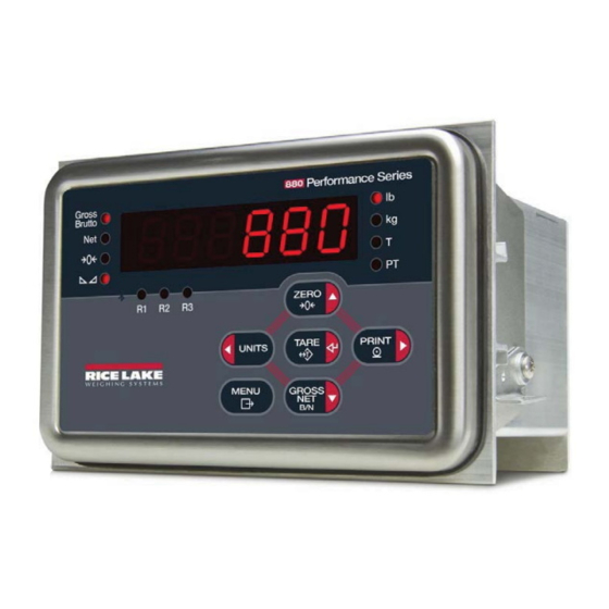
1.0 Introduction The 880 is a single-channel digital weight indicator housed in a panel mount enclosure. The front panel bezel can be sealed to a NEMA 4X/IP65 rating. The front panel consists of a 6-button keypad and a 6-digit, 14-segment LED display. -
Page 8: Safety
Do not operate or work on this equipment unless you have read and understand the instructions and warnings in this Manual. Failure to follow the instructions or heed the warnings could result in injury or death. Contact any Rice Lake Weighing Systems dealer for replacement manuals. Proper care is your responsibility. -
Page 9: Operating Modes
SCALE. The 880 also has an Audit Trail that can track changes to configuration and calibration, allowing the setup switch to be bypassed with Jumper J4 on the CPU board. Setup mode can then be accessed through the user setup mode. - Page 10 Indicates that a preset tare weight has been keyed in or entered via the EDP serial port. Bluetooth Not available at time of publication R1, R2 and R3 Range settings for multi interval or multi range Table 1-2. Annunciator Functions 880 Installation Manual...
-
Page 11: Indicator Operations
Indicator Operations Basic 880 operations are summarized below: 1.4.1 Toggle Gross/Net Mode GROSS 1. Press to toggle the display mode between gross and net. Net mode is only available if a tare value has been entered or acquired, the net value is the gross weight minus the tare. If no tare has been entered or acquired, the display remains in gross mode. -
Page 12: Print Ticket
TARE 7. Press to accept the displayed value. 8. Repeat the above steps to set PREACT, if enabled MENU 9. When all settings have been made, press to return to weighing mode. 880 Installation Manual... -
Page 13: Set Time And Date
Setpoint Value and Preact Value may be accessible from the front panel in weigh mode. Note Some indicator configurations may not allow setpoint values to be changed through the front panel or may require a password to display or change the setpoint value. Turn Setpoint On or Off To turn a setpoint off at the front panel: . -
Page 14: Clear The Accumulator
If there is no tare in the system, the value displayed will be zero and the Gross and Net LED will be turned off. See Section 9.12 for more information pertaining to the regulatory mode of operation. 880 Installation Manual... -
Page 15: Installation
Installation This section describes procedures for connecting load cells, digital I/O, and serial communications cables to the 880 indicator. Instructions for replacement of the circuit boards are included, along with assembly drawings and parts lists for the service technician. CAUTION •... -
Page 16: Panel Mount Installation
" " " Figure 2-1. 880 Panel Mount Dimensions Use the pattern and dimensions shown in Figure 2-2 to lay out the panel cutout for the stainless steel panel mount enclosure. See Figure for enclosure dimensions. 1. Mark panel for installation using the DIN rail backer plate and cut the five holes required for mounting. - Page 17 Panel for mounting indicator Din Rail Mounting Plate Important Ensure gasket is seated properly on display assembly before mounting. Display Assembly 6-32 Kep Nuts Front of panel Back of panel Figure 2-3. Mounting Display Assembly 5. Connect the cable assembly to the controller assembly. 6.
-
Page 18: Mounting The Controller Assembly Remotely
Controller Assembly can be mounted remotely on a standard 35 mm DIN rail up to 250 ft from display. When mounting the display Function remotely from the controller assembly, connect to this terminal. Figure 2-5. Mount Controller Assembly Remotely 880 Installation Manual... -
Page 19: Controller Box Disassembly
Controller Box Disassembly has no on/off switch. Before opening the unit, ensure the power cord is disconnected from the WARNING power outlet. Enclosure disassembly is not required to make connections for load cells, serial communications, or Note digital I/O. These connectors are all externally mounted on the back of the controller. 1. -
Page 20: Remove Backplate Of Controller Assembly
Corner Screws Figure 2-7. Remove Controller Assembly Backplate 1. Remove four corner screws, four center screws and the configuration access screw from the backplate. 2. Pull backplate from the controller unit. 3. To reinstall reverse the steps above. 880 Installation Manual... -
Page 21: Display Board Replacement
6. To replace the display board, reverse the above procedure. Cable Connections The 880 has three external connectors, a terminal connector for the power cord, and a cutout for installed options. Enclosure disassembly is not required to make connections to load cells, communications, digital inputs, and digital outputs. -
Page 22: Power Connections
2.5.2 Power Connections Power connections to the 880 Panel Mount are shown below. • Part number 152334 is used to connect AC power to the power supply board. • Part number 15888 is used to connect DC power to the power supply board. -
Page 23: Cpu Board
CPU Board Audit Jumper Figure 2-10. 880 CPU Board Connectors • Load cell (J1) • DIO (J2) • Comm 1 (J3) • USB Micro Device (J4) • USB Host (J5) • Ethernet TCP/IP (J6) • Opt Header (J8) • Power Board (J7) The Comm 1 port supports RS-232 or RS-485 communications;... -
Page 24: Board Replacement
2.6.1 Board Replacement If you must remove the 880 CPU board, use the following procedure: 1. Disconnect power to the indicator. 2. Unplug all connectors from the backplate. See Figure 2-10 for connector locations. 3. Remove the controller box from the DIN rail (see Section 2.3). -
Page 25: Digital I/O
DIO4 Table 2-4. J6 Pin Assignments (Digital I/O) Option Cards Connector J2 is reserved for option cards. Table 2-5 lists the options available for the 880 Indicator. Each kit includes instructions for installing and setting up the option. Option Addendum Part Number... -
Page 26: Replacement Parts
Replacement Parts Figure 2-13. 880 Indicator Parts Illustration 880 Installation Manual... - Page 27 Item No. Part No. Description (Quantity) 151674 Display Assembly, 880 Panel Mount (Includes items 1-7) 131740 Overlay, Membrane Switch 151663 Faceplate, Display 880 151667 Gasket, Faceplate 880 131598 Board Assy, 880 LED Disp. 14822 Screw, Mach 4-40NC x 1/4 156439...
-
Page 28: Configuration
Configuration To configure the 880 indicator, the indicator must be placed in setup mode. The setup switch is accessed through a small hole on the enclosure backplate, insert a nonconductive tool into the access hole and press the configuration switch. Indicator display changes to show... -
Page 29: User Setup Menu
User Setup Menu The 880 indicator can be configured using a series of menus accessed through the indicator front panel when the indicator is in user setup mode or setup mode. Table 3-1 summarizes the functions of the user setup menu. - Page 30 After the number desired is displayed, press ENTER. The decimal point will begin flashing if a decimal value is allowed. To move the decimal, to move the decimal position. Press ENTER when done. Figure 3-5. Editing Procedure for Numeric Values 880 Installation Manual...
-
Page 31: Alphanumeric Entry Procedure
Table 3-2. Editing Procedure for Numeric Values Menu Structures and Parameter Descriptions The following sections provide graphic representations of the 880 menu structures. In the actual menu structure, the settings you choose under each parameter are arranged horizontally. To save page space, menu choices are shown in vertical columns. -
Page 32: Setup Menu
Set print format used for header, gross, net, truck in/out, setpoint and auxiliary ticket formats. NFMT ACCFMT SPFMT HDRFMT SETPTS SP CFG Configure setpoints and batching mode. BATCHG DIGIO SLOT 0 Assigns digital input/output functions. Table 3-4. Setup Menu Parameters 880 Installation Manual... -
Page 33: Scale Menu
SETUP Menu Parameter Choices Description ALGOUT MODE Analog Output – configure analog output module OUTPUT ERRACT MINNEG MAXNEG TWZERO TWSPAN VERS SOFTWR Display installed software version number. DEFALT Table 3-4. Setup Menu Parameters (Continued) 3.2.3 Scale Menu ..SETUP .. - Page 34 Tare function – Enables or disables push-button and keyed tare. NOTARE BOTH – Both push-button and keyed tares are enabled PBTARE NOTARE – No tare allowed (gross mode only) KEYED PBTARE – Push-button tares enabled KEYED – Keyed tare enabled Table 3-5. Scale Menu Parameters 880 Installation Manual...
- Page 35 SCALE Menu Parameter Choices Description PWRUPM Power up mode. DELAY GO - In GO mode, the indicator goes into operation immediately after a brief power up display test. DELAY - the indicator performs a power up display test, then enters a 30-second warm up period.
-
Page 36: Format Menu
88888.8 10000 888880 weight 888888 weight weight 888888 8.88888 888880 888880 88.8888 8.88888 8.88888 888.888 88.8888 88.8888 8888.88 888.888 888.888 88888.8 NONE 8888.88 8888.88 If SPLIT = 2RNG, 3RNG, 2INTVL, or 3INTVL Figure 3-9. Format Menu Structure 880 Installation Manual... - Page 37 FORMAT Menu Parameter Choices Description If SPLIT = ON DECPNT Primary Units DSPDIV UNITS DECPNT Secondary Units DSPDIV UNITS If SPLIT = OFF submenu DECPNT 888888 Decimal Point Location – Specifies the location of the decimal point or dummy zeroes in the 888880 unit display.
-
Page 38: Calibration Menu
Press ENTER to recall the last established push button zero to allow calibration without removing weight from scale. See Section 4.4. TEMP — Press ENTER to temporarily zero the displayed weight from a loaded scale. See Section 4.5. Table 3-7. Calibration Menu Parameters 880 Installation Manual... -
Page 39: Feature Menu
3.2.6 Feature Menu See Section 7.0 for information about custom print formatting..SETUP CONFIG ..FEATUR REGION CONSC# PASSWD 000000 CURVAL RESVAL USER SETUP Figure 3-12 KEYLCK LOCALE LATUDE ELEVAT 0-90 -9999 to +9999 Shown if LOCALE is ON ZERO GRSNET UNITS... - Page 40 Overriding passwords will clear configuration and calibration settings. To Note preserve settings (i.e., ID information), use Revolution software to upload your data to a PC, then download it back to the 880 after the password override is performed. KEYLCK ZERO Disables the listed keys.
-
Page 41: Region Menu
3.2.7 Region Menu ..SETUP ..FEATUR REGION REGULA REGWOR DECFMT TIME DATE NTEP GROSS DFORMT D SEP CANADA BRUTTO COMMA MMDDY4 SLASH 000000 INDUST DDMMY4 DASH NONE Y4MMDD SEMI OIML Y4DDMM TFORMT T SEP MMDDY2 12 HOUR COLON XX.XXAM DDMMY2 See INDUST... - Page 42 Allow negative or zero tare. CTARE Allow CLEAR key to clear tare/accumulator. PRTMOT Allow print while in motion. PRTPT Add PT to keyed tare print. OVRBAS CALIB Zero base for overload calculation. SCALE CALIB = Calibrate Zero SCALE = Scale Zero 880 Installation Manual...
-
Page 43: Ports Menu
REGION Menu, REGULA / INDUST Submenu Parameter Choices Description AUDAG NTEP Selects the agency having jurisdiction over the scale site. CANADA • OIML, NTEP, and CANADA modes allow a tare to be acquired at any weight greater than zero. NONE allows tares to be acquired at any weight value. A tare can be NONE cleared only if the gross weight is at no load. - Page 44 Port to use for communications on the 880. 10001 RMOTIP 000.000.000.000 Remote IP address – IP address of the remote unit the 880 will connect to. Valid IP Address RMOTPT Remote port – port number on the remote unit the 880 will connect to.
-
Page 45: Com Menu
3.2.9 Com Menu ..SETUP ..PORTS USBCOM TERMIN ECHO TRIGGE BAUD BITS STOP B RESPNS CR/LF COMAND 9600 8NONE STRIND 19200 7EVEN 7ODD 28800 STRLFT REMOTE 38400 57600 115200 Not available in USBCOM 1200 2400 4800 EOLDLY TYPE ADDRES PRNMSG... - Page 46 Configures the port to operate as a serial scale input. BAUD 9600 Port baud rate. 19200 28800 38400 57600 115200 1200 2400 4800 BITS 8NONE Port data bits and parity. 7EVEN 7ODD Table 3-11. COM Menu Parameters 880 Installation Manual...
-
Page 47: Print Format Menu
COM Menu Parameter Choices Description STOP B Stop Bits – selects the number of stop bits transmitted and the number of stop bits expected to be received by the port PRNMSG Print message – display a message when a print is transmitted on this port. SFMT format Stream format –... -
Page 48: Setpoints Menu
MANUAL SETPT1 SETPT2-20 Same as SETPT1 GROSS See Menu Layout Level A -GROSS -NET %REL PAUSE DELAY See Menu Layout WAITSS Level B COUNTR TIMER AUTJOG See Menu Layout Level C CONCUR Figure 3-16. Setpoint Menu Structure 880 Installation Manual... - Page 49 GROSS, NET, -GROSS, -NET, %REL VALUE TRIP BANDVAL HYSTER PREACT PREVAL number number number number HIGHER LOWER If PREACT is If TRIP= If TRIP= ON or LEARN INBAND LEARN INBAND or HIGHER or OUTBAND LOWER OUTBAN PREADJ PRESTA PCOUNT BATSEQ CLRACM RELNUM 1–20...
- Page 50 Based on which DIGIO SLOT 1 are config as OUTPUT SLOT 1 - if RELAY option board is installed. SLOT 0 - if any DIGIO are configured as OUTPUT. Figure 3-19. Setpoint Menu Structure - Level C 880 Installation Manual...
- Page 51 SETPTS Menu Parameter Choices Description Level 2 submenus SETPT 1– Specifies the setpoint kind. SETPT 20 GROSS GROSS, NET, –GROSS, –NET, %REL setpoint kinds can be used as either batch or continuous setpoints. –GROSS –NET PAUSE, DELAY, WAITSS, COUNTR and AUTJOG setpoint kinds can only be used in %REL batch sequences.
- Page 52 The special value zero indicates that no branch is taken. SENSE NORMAL Specifies whether the state of the digital output associated with this setpoint is inverted INVERT when the setpoint is satisfied. 880 Installation Manual...
-
Page 53: Digital Input Menu
3.2.12 Digital Input Menu ..SETUP ..DIGIO SLOT 0 BIT 1 BIT 2-4 Same as SLOT 0 PRINT BIT 1 ZERO TARE UNITS CLEAR DSPACC DSPTAR NT/GRS CLRCN BATRUN BATSTR BATPAS BATRST BATSTP OUTPUT Figure 3-20. Digital I/O Menu DIGIO Menu Parameter Choices... -
Page 54: Analog Output Menu
Calibrate zero. Adjust the analog output zero calibration. See Section 9.11 on page 92. number TWSPAN 000000 Calibrate span. Adjust the analog output span calibration. See Section 9.11 on page 92 number Table 3-14. Analog Output Menu Parameters 880 Installation Manual... -
Page 55: Version Menu
3.2.14 Version Menu The VERS menu is used to check the software version installed in the indicator and to set the indicator configuration to factory defaults..SETUP ..VERS SOFTWR DEFALT V XX.XX LRV X.XX Figure 3-22. Version Menu Structure VERSION Menu Parameter Choices... -
Page 56: Calibration
Calibration ® The 880 can be calibrated using the front panel, EDP commands, or Revolution Calibration consists of the following steps: • Zero calibration • Entering the test weight value • Span calibration • Optional five-point linearization • Optional rezero calibration for test weights using hooks or chains •... -
Page 57: Front Panel Calibration
Front Panel Calibration MENU 1. Press , then navigate to (see Figure 4-1). CALIBR 2. Press to go to the parameter. TARE WZERO WZERO is used for most normal calibrations with an empty scale. If a special situation exists, where a LAST or Note TEMP zero may be used, refer to Section 4.4 or Section 4.5 for more information before performing a WZERO calibration. -
Page 58: Five-Point Linearization
Calibrating, Please Wait When complete, is displayed. LAST Note For more information on LAST or TEMP see Section 4.4 or Section 4.5. MENU 4. Press to return to weigh mode. 880 Installation Manual... -
Page 59: Edp Command Calibration
» 2. From Revolution, select File The Select Indicator dialog box appears. 3. Select 880 and click 4. From the Communications menu, select Connect 5. From the left pane, expand the Scale selection and click the button. -
Page 60: Last - Calibrating Zero Without Removing Test Weights
LATUDE (latitude) and ELEVAT (elevation in meters, relative to sea level) parameters set before calibrating the indicator. If the indicator is later installed at a different location, gravity compensation can be applied to a pre-calibrated indicator by adjusting the LATUDE and ELEVAT parameters. 880 Installation Manual... -
Page 61: Using Revolution
TCP/IP connections to the indicator Connecting to the Indicator Connect the PC serial port to the COM (COM 1), USBCOM (COM 2) or EtherNet port of the 880, then click in the toolbar. Revolution attempts to establish communications to the indicator. If communications... - Page 62 3. If the file is a new configuration file, click the menu and choose from the menu options. File Save As Revolution prompts for any changes to the file name and where to store the file on the PC’s hard drive. 880 Installation Manual...
-
Page 63: Revolution Help
Downloading to the Indicator function on the Revolution Communications menu allows a Revolution configuration Download Configuration file (with or without scale calibration data) or ticket formats to be downloaded to a connected indicator in user setup mode. function on the Communications menu allows you to download only the currently displayed Download Section object, such as contact information for a scale configuration. -
Page 64: Edp Commands
6.0 EDP Commands The 880 indicator can be controlled by a personal computer or terminal connected to the EDP commands which can simulate front panel key press functions, display and change setup parameters, and perform reporting functions. The EDP Command Set... -
Page 65: Reporting Commands
000=none, 085=relay card, 153=analog output card, 170=CompactCom card Example response with a relay card installed: HARDWARE=085 VERSION Return the 880 software version DISPLAYVERSION Return the display module software version Return the current displayed weight with units identifier, see Section 9.4 Return the current weight and annunciator status, see Section 9.4... - Page 66 888888, 888880, 8.88888, 88.8888, 888.888, 8888.88, 88888.8 SC.SEC.DSPDIV#1 DSPDIV Display divisions. (for secondary units) 1D, 2D, 5D SC.SEC.UNITS#1 UNITS Specifies secondary units for displayed and LB, KG, OZ, TN, T, G, NONE printed weight. Table 6-4. FORMAT EDP Commands 880 Installation Manual...
- Page 67 Calibration Menu Command Menu Description Choices / Range SC.WZERO#1 WZERO Perform zero calibration SC.WSPAN#1 WSPAN Perform span calibration SC.LC.CD#1 Raw count at zero -2147483646 to 2147483647 SC.LC.CW#1 Raw count at span -2147483646 to 2147483647 SC.LC.CZ#1 -2147483646 to 2147483647 SC.REZERO#1 REZERO Perform zero caibration SC.WLIN.C1#1 Calibrate linearization point 1...
- Page 68 String transmitted for the <M> token for tare weight. Alphanumeric, Max Length: 8 STR.ZERO String transmitted for the <S> token when the scale is at Alphanumeric, Max Length: 2 center of zero. Table 6-9. Stream Tokens EDP Commands 880 Installation Manual...
- Page 69 Feature Menu Command Menu Description Choices / Range CONSNUM CURVAL Consecutive numbering 0 – 999999 CONSTUP RESVAL Consecutive number startup value 0 – 999999 DECFMT DECFMT Decimal format DOT, COMMA GRAVADJ LOCALE Locale - must be enabled for latitude and elevation OFF, ON LAT.LOC LATUDE...
- Page 70 RELNUM Relative setpoint number 1- 20 SP.SENSE#n SENSE Digital output sense NORMAL, INVERT SP.DSLOT#n SLOT Digital output slot NONE, SLOT0, SLOT1 SP.START#n START Starting setpoint number for TIMER and CONCUR 1- 20 Table 6-15. Setpoints EDP Commands 880 Installation Manual...
- Page 71 Command Menu Description Choices / Range SP.TRIP#n TRIP Specifies when the setpoint is satisfied when HIGHER, LOWER, INBAND, compared to value OUTBAND SP.VALUE#n VALUE Setpoint value Range: 0 - 65535 (for the COUNTR and DELAY setpoints) 0 - 999999 (for the GROSS, NET, and %REL setpoints) BATCHNG BATCHG...
- Page 72 Specify ON if the minimum weight is a negative value. OFF, ON ALG.MAX#1 Maximum value tracked Range: 0 - 999999 ALG.MAXNEG#1 MAXNEG Specify ON if the maximum weight is a negative value. OFF, ON Table 6-18. ALGOUT EDP Commands 880 Installation Manual...
-
Page 73: Normal Mode Commands
6.1.5 Normal Mode Commands The normal mode commands (see Table 6-19) transmit data to the EDP port on demand. The SX command is valid only in normal operating mode; all other commands are valid in either setup or normal mode. Command Function CONSNUM... -
Page 74: Error Commands Output
BATRESET Batch reset. Stops the program and resets the batch program to the first batch step. Run the BATRESET command after making changes to the batch configuration. Table 6-22. Batching Control Commands 880 Installation Manual... -
Page 75: Print Formatting
Print Formatting Commands Table 7-1 lists commands you can use to format the 880 print formats. Commands included in the format strings must be enclosed between < and > delimiters. Any characters outside of the delimiters are printed as text on the ticket. -
Page 76: Default Ticket Formats
Default Ticket Formats Table 7-2 shows the default print formats for the 880 and lists the conditions under which each print format is used. format is used to specify header information that can be used by the other ticket formats. The contents... -
Page 77: Customizing Print Formats
7.3.1 Using the EDP Commands With a personal computer, terminal, or remote keyboard attached to the 880, you can use the EDP command set to customize the print format strings. To view the current setting of a format string type the name of the print format, followed by .FMT, and press . -
Page 78: Using Revolution
Using Revolution, you can type text directly into the grid, then select weight value fields from the tool bar and place them where you want them to appear on the printed ticket. Figure 7-2 shows an example of the Revolution print formatting grid. Need New Figure 7-2. Revolution Print Format Grid 880 Installation Manual... -
Page 79: Setpoints
Setpoints indicator provides 20 configurable setpoints for control of both indicator and external equipment functions. Setpoints can be configured to perform actions or functions based on specified parameter conditions. Parameters associated with various setpoint kinds can, for example, be configured to perform functions (print, tare, accumulate), to change the state of a digital output to control external equipment functions, or to make conditional decisions. - Page 80 The digital output associated with this setpoint becomes active when the START setpoint becomes the current batch step and remains active until the timer expires. Table 8-1. Setpoint Kinds (Continued) 880 Installation Manual...
-
Page 81: Batch Operations
Batch Operations Batches are controled by digital inputs or EDP commands. (BATRUN digital input) If a BATRUN digital input is configured, it must be active (low) for a batch to Batch Run be started, or for it to continue to run. If a batch is running and the input becomes inactive (high), it will stop the batch at the current batch setpoint and turn off all associated digital outputs. - Page 82 1. Turn 3-way switch to ABORT. 2. Unlock STOP button (OUT position). 3. Turn 3-way switch to START. Use this procedure (or the BATRESET serial command) to initialize the new batch routine following any change Note to the setpoint configuration. 880 Installation Manual...
-
Page 83: Batching Examples
Batching Examples DIGIO, SLOT 0, BIT 1 = BATSTR Note DIGIO, SLOT 0, BIT 2, 3 and 4 = OUTPUT Example 1 The following example is used to dispense 100-LB drafts, automatically refilling a hopper to 1000 LB gross weight once the gross weight has dropped below 300 LB. - Page 84 Setpoint 4 uses digital output slot 0, bit 3, to fill the hopper to a net weight of 1000 LB. KIND=NET VALUE=1000 TRIP=HIGHER BATSEQ=ON SLOT = SLOT 0 DIGOUT=3 Setpoint 5 operates digital output slot 0, bit 3, while Setpoint 3 is active, providing simultaneous two-speed filling. KIND=CONCUR VALUE=0 START=3 END=4 SLOT = SLOT 0 DIGOUT=3 880 Installation Manual...
-
Page 85: Appendix
Appendix Error Messages The 880 indicator provides a number of error messages. When an error occurs, the message is shown on the indicator display. Error conditions can also be checked remotely by using the XE EDP command as described in Section 9.3. -
Page 86: Using The Hardware Command
BATTERYERR 0x00000040 32768 GRAVERR 0x00008000 65536 ADPHYSICALERR 0x00010000 131072 TAREERR 0x00020000 262144 EACCOVER 0x00040000 524288 STRINGERR 0x00080000 1048576 RESERVED_PF 0x00100000 2097152 RTCERR 0x00200000 4194304 MISSINGHWERR 0x00400000 8388608 CFGCONFLICTERR 0x00800000 16777216 UNRECOVERABLEERR 0x01000000 Table 9-3. Error Commands Output 880 Installation Manual... -
Page 87: Status Messages
Status Messages Two EDP command, P, can be used to provide status about the indicator. • The P EDP command returns whatever is currently shown in the indicator’s primary display area. PPPPPPP uu where: • is the information shown on the primary display PPPPPPP •... -
Page 88: Data Formats
Print Output Serial Data Format When print format is configured for the demand (print) port in the setup menus, the 880 uses a data string formatted for a basic ticket printout. The particular ticket format printed depends on the indicator configuration. See Section 7.0 for print formatting. - Page 89 If the initiating device address matches the port address of a 880 on the RS-485 network, that indicator responds. The responding indicator uses the format shown in Figure 9-3: <STX> <ADDRESS> <RESPONSE> <ETX> <CR> Response commands from ASCII 13 ASCII 02...
-
Page 90: Custom Stream Formatting
Custom Stream Formatting A serial port on the 880 main board can be configured to stream scale data out. The format of the streamed data can be configured for the COM and USBCOM ports indiviually through the front panel using the tokens in Table 9-5. - Page 91 Format Identifier Defined By Description Configuration =00 (not used) =01 if secondary DSPDIV=1 =10 if secondary DSPDIV=2 =11 if secondary DSPDIV=5 Configuration =00 (not used) =01 if tertiary* DSPDIV=1 =10 if tertiary* DSPDIV=2 =11 if tertiary* DSPDIV=5 Configuration =000 (not used) =001 if current DECPNT=888880 =010 if current DECPNT=888888 =011 if current DECPNT=88888.8...
- Page 92 New Line. <nnn> ASCII character (nnn = decimal value of ASCII character). Used for inserting control characters (<002> for an STX, for example) in the output. * Tertiary (Range/Interval 3) Table 9-5. Custom Stream Format Identifiers (Continued) 880 Installation Manual...
-
Page 93: Stream Formatting Examples
NOTE: Identifiers must be entered beginning with the high-order bit (bit 7–bit 0) of the Toledo status word. Status Word A contains the following fields. Equivalent 880 format identifiers are shown in parentheses. Bit 7: parity (B2) Bit 6: always 0 (B0) Bit 5: always 1 (B1) Bits 3–4: display divisions (B13) -
Page 94: Cardinal 738 Indicator
<units> The Cardinal uses two-character, lower-case units identifiers. The commands to set these tokens in the 880 include: STR.PRI=lb (options: kg, g, tn, t , gr, oz, or sp), STR.SEC=kg (options: lb, g, tn, t , gr, oz, or sp). -
Page 95: Weightronix Wi 120 Indicator
<units> The Weightronix uses two-character, lower-case units identifiers. The commands to set these tokens in the 880 include: STR.PRI=lb (options: kg, g, tn, t , gr, oz, or sp), STR.SEC=kg (options: lb, g, tn, t , gr, oz, or sp). -
Page 96: Ascii Character Chart
Use the decimal values for ASCII characters listed in Tables 9-9 and 9-10 when specifying print format strings on the 880 PFORMT menu. The actual character printed depends on the character mapping used by the output device. The 880 can send or receive any ASCII character value (decimal 0–255). Due to limitations of the indicator display, some characters cannot be shown. -
Page 97: Digital Filtering
Table 9-10. ASCII Character Chart (Part 2) 9.10 Digital Filtering Digital filtering can be used to create a stable scale reading in challenging environments. The 880 has two filtering methods that can be set; Sample rate and Digital filter. 9.10.1 Sample Rate: The Sample rate should be set first. -
Page 98: Digital Filter
• Press to increment or decrement the value. TARE • Press to move to the decimal point entry. • Press to adjust the decimal point placement. TARE • Press to accept the displayed value. 880 Installation Manual... - Page 99 4. Adjust span calibration: • Scroll to the TWSPAN parameter. • Press , 000000 will display. • Set the parameter to match the reading from the multimeter. • Press to select the digit. • Press to increment or decrement the value. TARE •...
-
Page 100: Specifications
4 Outputs, current limited darlington pair with TTL pull-up, 40V withstand Digital Filter Adaptive filtering, sensitivity and threshold Serial Communications RS-232 Full Duplex RS-485 Half Duplex USB Type A Connector 2.0 USB Micro A/B Connector 2.0 EtherNet EtherNet TCP/IP 880 Installation Manual... -
Page 101: Limited Warranty
880 Limited Warranty Rice Lake Weighing Systems (RLWS) warrants that all RLWS equipment and systems properly installed by a Distributor or Original Equipment Manufacturer (OEM) will operate per written specifications as confirmed by the Distributor/OEM and accepted by RLWS. All systems and components are warranted against defects in materials and workmanship for two years. - Page 103 230 W. Coleman St. Rice Lake, WI 54868 U.S. 800-472-6703 Canada/Mexico 800-321-6703 International 715-234-9171 Europe +31 (0) 88 2349171 www.ricelake.com www.ricelake.mx www.ricelake.eu www.ricelake.co.in m.ricelake.com © Rice Lake Weighing Systems PN 158387 10/2013...
Need help?
Do you have a question about the 880 and is the answer not in the manual?
Questions and answers